

Page 1

Quick Guide
Original instructions
Motor controller CMMB
Festo AG & Co. KG
Ruiter Straße 82
73734 Esslingen
Germany
+49 711 347-0
www.festo.com
8068721
2017-07a
[8069599]
1
2
3
Front view of CMMB series motor controller
X1 Reserved connector
X2 Power & motor connector
X3 RS232 connector
X4 Multi function connector
X5 Encoder connector
1 Front panel
2 Ground
3 Charge lamp
L1C
L2C
L1
L2
U
V
W
PE
Motor
Power Cable
Motor Encoder Cable
Motor Brake Cable
RS232 Cable
Brake 24V
Power Supply
RB1
RB-
Braking
Resistor
220VAC
Power Supply
Circuit Breaker
(MCCB)
Noise Filter
(NF)
Magnetic
Contactor
(MC)
Fuse 1
Fuse 2
N L
Easy Use function
The Easy Use function helps users set up the CMMB motor controller for
the main types of applications in a very short time. The LED panel guides
the user step by step through the settings of the few most important
parameters in order to prepare the controller for the desired application.
The servo control loops of the motor controller are pre-congured to useful default settings which are adequate for many applications at as they
are. A robust auto-tuning function can be used additionally to identify the
applied mechanical system more precisely. After that, the user only needs
to adjust the controller’s servo performance with the stiffness parameter.
Setup process with Easy Use function
The process for setting up the CMMB motor controller with the Easy Use
function follows a simple procedure.
Step 1: The parameters of the EASY panel menu have to be accessed and
conrmed, or set one by one. The auto-recognized motor type can be
conrmed, the control interface has to be selected, interface-related main
parameters have to be set and the mechanical and control application
types must be chosen. Afterwards, these parameter have to be stored
and the controller has to be rebooted. As a result of these settings, the
controller is congured for a suitable I/O setting and the servo control
loop parameters are set to matching defaults. The controller is ready for
use for a wide range of standard applications and can be tested.
Step 2: If the servo control performance of the controller has to be further
improved, the tunE panel menu must be accessed. With the help of the
functions in this menu, the controller can start an auto-tuning motor run
in order to identify motor load conditions and measure load inertia. The
controller detects the ratio of the load inertia relative to motor inertia and
tunes the servo loops according to one single parameter, namely stiffness. Stiffness can be easily adjusted up or down in the tunE menu with
the panel buttons. during the application can be test-run via the selected
command interface. After nding the best value for stiffness, the tunE
parameters need to be stored and the controller is nally ready for use.
If adjustment of stiffness does not result in the required performance, the
PC software “CMMB congurator” can be used to for further optimisation.
Safety and requirements for product use
Warning
Danger of electric shock
• If cables are not mounted to the plug (X2).
• If connecting cables are disconnected when energised.
Touching live parts causes severe injuries and can lead to death.
The product may only be operated in the installed state and when all
safeguards have been initiated.
Before touching live parts during maintenance, repair and cleaning work
and after been long service interruptions:
1. Switch off power to the electrical equipment via the mains switch and
secure it against being switched on again.
2. After switching-off, allow to discharge for at least 5 minutes and check
that power is turned off before accessing the controller. Make sure that
the charge lamp on the front of the controller is off.
Warning
Danger of electric shock
Motor controllers are devices with increased leakage current (> 3.5 mA). If
wiring is incorrect or the device is defective, high voltage can occur on the
housing, which can result in serious injury or even death if the housing is
touched.
• Before commissioning, also for brief measuring and test purposes, con-
nect the PE protective conductor.
• Observe the regulations of EN 60204-1 for the protective earthing.
1
2
1 Pin 1 2 Pin 19
X4 – Multi-function connector
Pin 1 OUT1+ Pin 19 AIN1+
Pin 2 COMI Pin 20 OUT5
Pin 3 OUT1- Pin 21 AIN1-
Pin 4 DIN1 Pin 22 +5V
Pin 5 OUT2+ Pin 23 AIN2+
Pin 6 DIN2 Pin 24 GND
Pin 7 OUT2- Pin 25 AIN2-
Pin 8 DIN3 Pin 26 ENCO_Z
Pin 9 OUT3 Pin 27 MA+
Pin 10 DIN4 Pin 28 ENCO_/Z
Pin 11 OUT4 Pin 29 MA-
Pin 12 DIN5 Pin 30 ENCO_B
Pin 13 COMO Pin 31 MB+
Pin 14 DIN6 Pin 32 ENCO_/B
Pin 15 VDD Pin 33 MB-
Pin 16 DIN7 Pin 34 ENCO_A
Pin 17 VEE Pin 35 MZ+
Pin 18 MZ- Pin 36 ENCO_/A
1
X2 – Power connector
Pin 1 L1C Control power input L/N
Pin 2 L2C
Pin 3 L1 Drive power input L/N
Pin 4 L2
Pin 5 DC+
/RB1
DC+ DC bus+
RB1 External braking resistor input
Pin 6 RB2 Internal braking resistor input
Pin 7 RB- External braking resistor input
Pin 8 DC- DC bus-
Pin 9 U U/V/W phase power output for
servo motor
Pin 10 V
Pin 11 W
Short-circuit DC+ / RB1 and RB2 if choosing controller
internal braking resistor (power: 10 W).
Wire cross section for all pins:
AWG 22 (0.32 mm²) to AWG 14 (2.1 mm²)
1
Pin 1
Warning
It is forbidden to use the internal braking resistor if average brake power
is greater than 10 W.
Model Fuse 1 Fuse 2
CMMB-AS-01 1 A 3.5 A
CMMB-AS-02 1 A 3.5 A
CMMB-AS-04 1 A 7 A
CMMB-AS-07 1 A 15 A
4 5 5 6
2 3
3 4
1 2
The following gure shows the wiring of X4 with default IO function. More
IO functions can be dened with the digital panel or PC software.
Digital
Input
Enable
Reset Errors
Start Homing
P limit +
P limit -
Home Signal
Input Common
PUL+ / CW+ / A+
PUL- / CW- / A-
DIR+ / CCW+ / B+
DIR- / CCW- / B-
Z+
Z-
Impulse
Command
(<500k)
Digital
Output
Ready
Motor Brake
Position Reached
Zero Speed
Error
Output Common
OUT1+
OUT1OUT2+
OUT2OUT3
OUT4
OUT5
COMO
1
3
5
7
9
11
20
13
ENCO_A
ENCO_/A
ENCO_B
ENCO_/B
ENCO_Z
ENCO_/Z
34
36
30
32
26
28
+5V
GND
22
24
+5V
GND
VDD
VEE
15
17
+24V
VEE
DIN1
DIN2
DIN3
DIN4
DIN5
DIN6
DIN7
COMI
4
6
8
10
12
14
16
2
MA+
MAMB+
MBMZ+
MZ-
27
29
31
33
35
18
Self-adapt
Self-adapt
Self-adapt
Internal 24V
Output
Internal 24V Output+
Internal 24V Output-
Internal 5V
Output
Internal 5V Output+
Internal 5V Output-
Encoder
Output
Encoder Out A+
Encoder Out AEncoder Out B+
Encoder Out BEncoder Out Z+
Encoder Out Z-
Analog
Speed
Analog
Torque
Analog
Max.Torque
AIN1+
AIN1AIN2+
AIN2-
19
21
23
25
A/D
Electrical installation
2
Parameter description
5
Default I/O function
4
Pin connection
3
General information / Preparation
1
Note
For all available product documentation www.festo.com/pk
Warning
Danger of electric shock
This product can cause a DC current in the protective ground conductor.
In cases where an error current protection unit (RCD) or an error current
monitoring device (RCM) is used to protect against direct or indirect con-
tact, only the Type B kind of RCD or RCM is permitted on the power supply
side of this product.
Intended use
The CMMB is intended for:
• Use in control cabinets for power supply to AC servo motors and their
regulation of torques (current), rotational speed and position.
The CMMB is intended for installation in machines or automated systems
and may only be used:
• When in excellent technical condition
• In original status without unauthorised modications
• Within the limits of the product dened by the technical data
• In an industrial environment
The product is intended for use in industrial areas. When used outside an
industrial environment, e.g. in commercial and mixed residential areas,
measures for radio interference suppression may be necessary.
Page 2
7 8
8 9
6 7
LED
Display
Parameters Description Default
EA01 Motor Type For a new motor controller, the set motor type is “00”
and “3030” appears at the LED display. If the new
motor controller is connected to a valid motor, the
motor type is auto-recognized and stored. The motor
type is auto-conrmed for the new motor controller.
The motor type stored in the controller and the
connected motor type are compared later on. If they
are different, “FFFF” ashes at the LED display . The
user needs to conrm the EA01 value or store motor
data and reboot the controller to eliminate this state.
/
EA02 Command Type The command type affects controller-internal interface
settings, the initial operating mode after power on and
the default settings for DIN- and OUT functions.
0: CW/CCW pulse train mode Operating mode = -4
1: P/D pulse train mode Operating mode = -4
2: A/B phase control
master/slave mode Operating mode = -4
6: Analog speed mode by AIN1 Operating mode = -3
7: Analog speed mode by AIN2 Operating mode = -3
8: Communication
9: Position table mode Operating mode = 1
1
EA03 Gear Factor
Numerator
Used when EA02 is set to 0-2. By default, the display
shows the values in decimal format. If the number is
greater than 10,000, the display is in hexadecimal
format. For gear factor 1 the pulse count of 65536
conforms to 1 revolution of the motor.
1000
EA04 Gear Factor
Denominator
1000
EA05 Analog Speed
Factor
Used when EA02 is set to 6 or 7.
The relationship between analog input voltage and
motor speed – the unit of measure is rpm/V.
Perhaps to set fail if the factor is too big when the
encoder is with high resolution. For controller use with
standard EMMB-AS motors, the maximum value is 374,
the maximum velocity is 3740 rpm/10 V.
300
EA06 The meaning of each digit of the LED display from right to left 1001
1. Load type
inuences the
control loop.
0: No load
1: Belt drive
2: Ball screw
2. Application,
inuences the
control loop.
0: P2P
1: CNC
2: Master/slave mode
3. Limit switch 0: Controller default
1: Delete the limit switch function
4. Alarm
output polarity
Polarity of OUT5. OUT5 is default to Error
0: Normally closed contacts
1: Normally open contacts
EA07 Homing
method
For example 35: Homing to actual position. 0
EA00 Save
Parameters
Write "1" to save all parameters.
Write "2" to save all parameters and restart the servo
(users must reboot the drive when changing the motor
type).
Write "3" to reboot the servo.
Write "10" to initialize the parameters.
Notice: After saving the parameters, the servo will
set the control loop according to the load type and
application.
/
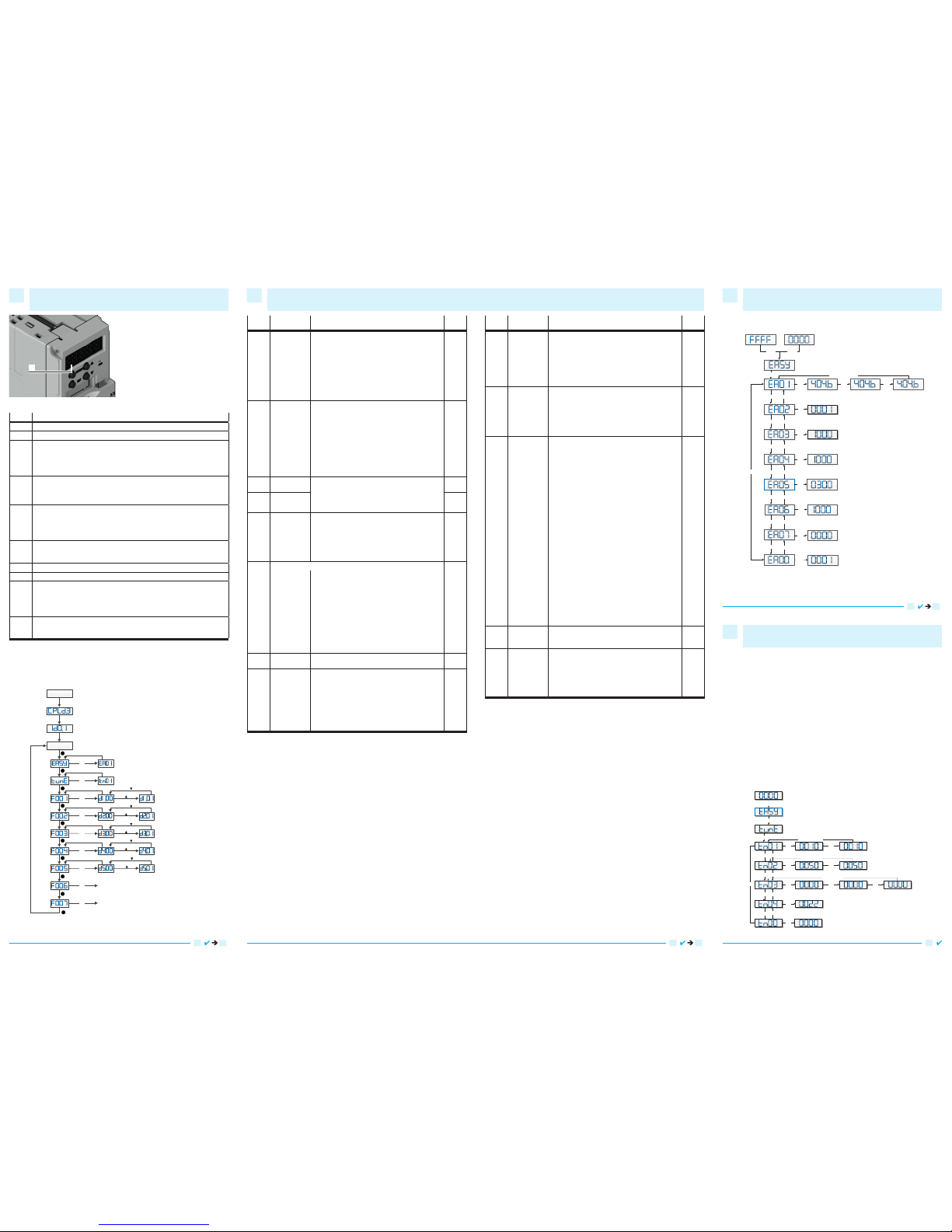
The tunE panel menu includes parameters and functions for auto-tuning
with inertia measurement and servo control loop adjustment via just one
parameter, namely stiffness.
After processing the EASY menu, the controller defaults the stiffness
value and the inertia ratio based on reasonable estimated values accord-
ing to load type and application settings in EA06.
If the inertia ratio is known based on the machine’s mechanical system
and the payload, the value can be entered directly in tn02 (see also
table 4-4). The inertia ratio does not need to be 100% correct to achieve
reasonable servo performance by adjustment of stiffness alone. But
the more accurate the inertia ratio, the better the tuning algorithm can
match the different servo control loops to each other. That’s why it is
highly advisable to obtain a precise inertia ratio result by means of inertia
measurement.
The following owchart and table explain the procedure for settings in
the tunE menu in detail.
SET
▲
▼▲
▼
▲
▼
▲
Stiffness
Write “1”to start
inertia ratio measuring
Measuring Distance,unit is 0.01 cycle
Inertia ratio, unit is 0.1
Write 1 to save all the parameters
Write 2 to save all the parameters and restart servo
MODE
MODE
Circle
SET SET
Long Press MODE
▼
LED is blinking,
Press MODE can shift.
the parameters below
display in the same way.
Confirm the parameter ,the
first dot on the right will
lighten. the parameters below
display in the same way.
SET
SET
SET
SET
SET SET
adjusted by “▼▲”level by level
and will be valid immediately
SET
Long Press MODE
Long Press MODE
Write automatically after inertia measuring.
Or written by user. adjusted by “▼▲”level by
level and will be valid immediately
The following owchart and table explain the procedure for settings in
the EASY menu in detail.
Command Type
Gear Factor Numerator
Gear Factor denominator
From right to left , each LED represent Load Type, Application,
Limited Switch, Polar of Alarm Output, please refer to Talbe-2
Analog Speed Factor ,Unit is rpm/V
Write“1”to save all the parameters.
Write“2”to save all the parameters and restart the servo
Write “3” to reboot the servo
Write “10” to initialize the parameters
Notice: Users MUST sav
e all parameters and reboot the
controller if changing the motor type
MODE MODE
SET
Motor Type
LED is blinking,Press MODE can
shift,the parameters below display
in the same way
SET
SET
Long press MODE
SET
SET
SET
SET
SET
SET
SET
▲
▼
Circle
Homing Method
▲
▼
▲
▼
▲
▼
▲
▼
▲
▼
▲
▼
SET
Display an switch functions
6
EASY and TunE parameters
7
Flowchart and description of the tunE menu
9
Flowchart and description of the EASY menu
8
9
LED
Display
Parameters Description Default
tn01 Stiffness Level of control stiffness from 0 to 31 determines the
bandwidth (BW) of the velocity loop and the position
loop. The larger the value, the greater the stiffness.
If this parameter is too large, gain will change
excessively and the machine will become unstable.
When setting tn01 via the up and down buttons on the
panel, entered values are valid immediately in order to
ensure the input of small change steps.
Belt:
10
Screw:
13
tn02 Inertia_Ratio Ratio of total inertia and motor inertia (unit: 0.1), for
example 30 represents an inertia ratio of 3.
This value becomes defaulted by the EASY procedure
and is measured by the inertia measuring function in
the tunE menu (tn03). When setting tn02 by the panel
up down buttons, the data will be valid immediately, to
ensure the input of small change steps.
Belt:
10
Screw:
50
tn03 Tuning_
Method
Writing 1 starts auto-tuning inertia measurement.
The controller is enabled and the motor executes an
oscillating motion for less than 1s.
If tuning is successful, Tuning_Method indicates a
value of 1. The measured inertia is used to determine
the Inertia_Ratio. Stiffness is set to 4 to 12 depending
on the inertia ratio. The control loop parameters are
set according to Stiffness and Inertia_Ratio.
If the inertia measurement fails, Tuning_Method
indicates the fail-reason:
0: The controller could not be enabled by any
reason.
-1: Inertia cannot be measured due to too little
motion or too little current.
-2: The measured inertia result is outside the valid
range.
-3: The resulting Inertia_Ratio value is greater than
250 (inertia ratio > 25). This is a possible result,
but the control loop will not be tuned.
-4: The resulting Inertia_Ratio value is larger than
500 (inertia ratio > 50). This is an uncertain result.
In the cases 0, -1, -2, -4 Inertia_Ratio is set to 30, in
the case -3 Inertia_Ratio is set as measured, Stiffness
is set to 7-10
In any fail case the control loop parameters are set
to Inertia_Ratio of 30 and the set Stiffness values. To
make the measured Inertia_Ratio of case -3 become
effective, the value of tn02 must be conrmed by SET.
-
tn04 Safe_Dist Inertia measuring distance (unit: 0.01 rev), for example
22 represents 0.22 motor revolutions. The maximum is
0.4 revolutions.
22
tn00 Saving
parameters
Write "1" to save all parameters.
Write "2" to save all parameters and restart the servo.
Write "3" to reboot the servo.
Write "10" to initialize the parameters.
Note: Users must save control and motor parameters
and reboot the controller when changing the motor
type.
-
1
1 Dot 1
Item Function
Dot 1 N/A
Dot 2 N/A
Dot 3 When setting parameters: distinguishes between the data for the current object
group and the object address inside the group. When the internal 32 bit data
appears at the display, the display is showing the high 16 bit of the current 32
bit data. Indicates that the earliest error information in the error history is being
displayed when the error history record in F007 appears at the display.
Dot 4 When setting parameters and displaying real-time data, indicates the format of
the data: HEX data when dot 4 is on and DEC data when dot 4 is off.
Indicates that the latest error information in the error history is being displayed
when the error history record in F007 appears at the display.
Dot 5 Lights up to indicates that data has been successfully modied when setting
parameters.
Lights up to indicate that internal data is being displayed when real-time data
appears.
The controller’s power stage is operative when dot 5 ickers.
MODE Switch function menu
When setting parameters, press briey to switch the setting bit, press and hold to
return to the last menu.
▲
Increases the value.
▼
Reduces the value.
SET Enter menu.
Check the values of the parameters.
Conrm the setting to access the next step.
When the internal 32 bit data appears at the display, press and hold to switch
high / low 16 bit.
Overall
ash
Error or warning status. Lit up for 1 s and dark for 1 s indicates a controller error.
Continuous ashing (3 consecutive rapid ashes) indicates that the controller is
in a warning state.
Panel menu structure and navigation
The following owchart shows the main structure of the panel. The user
can select single parameters, modify values and access special functions
using this ow. A list of all accessible parameters and values can be found
in chapter 9 in the manual.
Monitor State
SET
Switch on
Driver ID
MODE
MODE
MODE
MODE
MODE
MODE
MODE
MODE
MODE
MODE
SET
SET
SET
SET
SET
SET
Parameter Display
Control Loop
Parameter of IO and
Operation Mode
Motor Configuration
Driver Configuration
Error History
JOG Mode
SET
SET
CPU Version
Note for F006: Press ▼ until 6.15 appears, and press ▲ until 6.25 appears. Press SET to
enter the Jog mode and use ▲ and ▼ to rotate positive or negative. Jog speed can be
set by F003 -> d3.52 in unit of RPM.
 Loading...