

Page 1
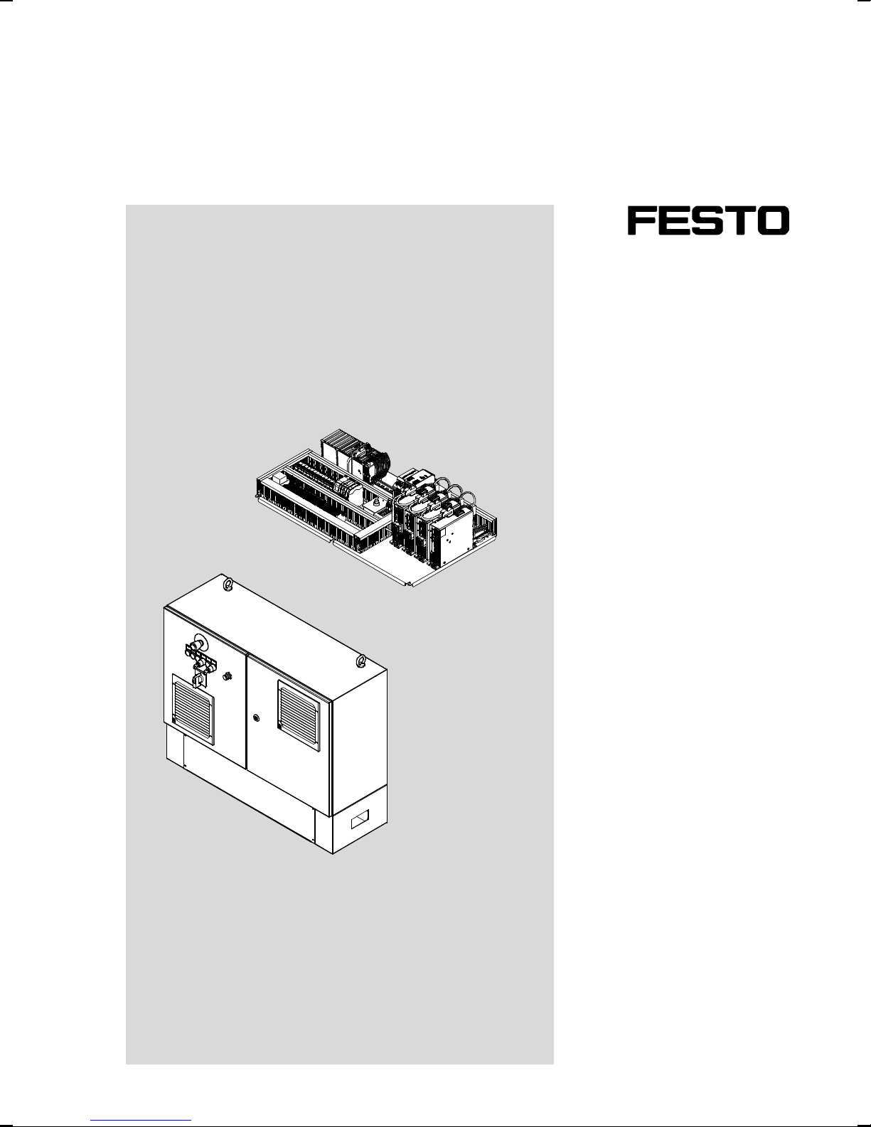
Control system
CMCA-...-B...
Description
Electrical
Installation
8036667
1405NH
[8036661]
Page 2
CMCA-...-B...
Translation of the original in structions
GDCP-CMCA-B-INST-EN
Codesys
®
is a registered trademark of its respective t rademark holder in certain countries.
Identification of hazards and instructions on how to prevent them:
Warning
Hazards that can cause death or serious injuries.
Caution
Hazards that can cause minor injuries or serious material damage.
Other symbols:
Note
Material damage or loss of function.
Recommendations, tips, references to other documentation.
Essential or useful accessories.
Information on environmentally sound usage.
Text designations:
• Activities that may be carried out in any order.
1. Activities that should be c arried out in the order stated.
– General lists.
2 Festo – GDCP-CMCA-B-INST-EN – 1405NH – English
Page 3

CMCA-...-B...
Table of Contents – CMCA-...-B...
1 Safety and requirements for product use 5......................................
1.1 Safety 5..................................................................
1.1.1 General safety information 5..........................................
1.1.2 Intended use 5.....................................................
1.1.3 Foreseeable misuse 6...............................................
1.2 Requirements for pro duct use 6...............................................
1.2.1 Qualification of specialized personnel 6.................................
1.2.2 Range of application and certifications 6................................
2 Transport and storage 7.....................................................
2.1 Transport 7................................................................
2.1.1 Dimensions and weights 7...........................................
2.2 Storage conditions 8........................................................
2.3 Unpacking 8...............................................................
2.3.1 Mounting plate 9...................................................
2.3.2 Control cabinet 10...................................................
2.4 Check the scope of delivery 13.................................................
3Overview 14................................................................
3.1 Function and application 14....................................................
3.2 Design 14..................................................................
3.2.1 External control elements and connections 14.............................
3.2.2 Internal components and connections 16.................................
3.2.3 Terminal strips 17...................................................
3.2.4 Circuit breakers 18..................................................
4 Mounting and installation 19..................................................
4.1 Mounting 19................................................................
4.1.1 Mounting plate 19...................................................
4.1.2 Control cabinet without base 20........................................
4.1.3 Control cabinet with base 21..........................................
Festo – GDCP-CMC A-B-INST-EN – 1405N H – English 3
Page 4

CMCA-...-B...
4.2 Electrical installation 22.......................................................
4.2.1 Safety instructions 22................................................
4.2.2 Design of the double-stack terminals 24.................................
4.2.3 Supply voltage 25...................................................
4.2.4 Power switch (mounting plate design) 25................................
4.2.5 Emergency stop switch (mounting plate design) 26.........................
4.2.6 External emergency stop circuits 27.....................................
4.2.7 Protective door switch 27.............................................
4.2.8 Control and signal elements 28.........................................
4.2.9 Mode selector 30....................................................
4.2.10 Kinematic drives 31..................................................
4.2.11 Connect limit switches 31.............................................
4.2.12 Rod loss detection (only for parallel kinematic system EXPT) 32...............
4.2.13 Axis of rotation reference sensor 32.....................................
4.2.14 Camera system 32...................................................
4.2.15 Lighting 32.........................................................
4.2.16 Freely usable outputs 33..............................................
4.2.17 Additional peripheral modules for the multi-axis controller 34................
5 Commissioning 35...........................................................
5.1 Checks before commissioning 35.......................................
6 Operation and diagnostics 36..................................................
6.1 Operation 36...............................................................
6.2 Maintenance and care 36......................................................
6.2.1 Control cabinet fan 36................................................
7 Module replacement and repair 37.............................................
7.1 Module replacement 37.......................................................
7.2 Repair 37..................................................................
7.3 Disposal 37................................................................
A Technical appendix 38........................................................
A.1 Technical data 38............................................................
A.1.1 Safety engineering 38................................................
A.1.2 General 38.........................................................
A.1.3 Electrical data 39....................................................
A.1.4 Operating and environmental conditions 39...............................
4 Festo – GDCP-CMCA-B-INST-EN – 1405NH – English
Page 5
1 Safety and requirements for product use
1 Safety and requirements for product use
1.1 Safety
1.1.1 General safety information
Warning
Danger of electric shock even if power switch is shut off.
The control system is only completely voltage-free if all supply lines have been switched
voltage-free.
• Switch off all supply lines (also external voltage) prior to assembly, installation and/
or maintenance work and secure them from being restarted accidentally.
• Switch the voltages back on only after completion of work.
Note
Damage to the product from incorrect ha ndling.
• Never pull or plug in the plug connectors and interfaces when powered.
• Observe the handling specifications for electrostatically sensitive devices.
1.1.2 Intended use
The control system CMCA-...-B... is intended to operate a kinematics system in the environment of a
machine or automated system.
• Use system only as follows:
– in perfect technical condition
– in original status, without unauthorised modifications
– within the limits of the product defined through the technical data ( A.1 Technical data)
– in an industrial environment
The safety circuit of the control solution CMCA-...-B... is only one part of the safety concept for a machine, whereby the safety concept must be based on a risk assessment of the entire machine to be
performed by the machine manufacturer.
Note
In the event of damage caused by unauthorised manipulation or other than intended
use, the guarantee is invalidated and the manufacturer is not liable for damages.
Festo – GDCP-CMC A-B-INST-EN – 1405N H – English 5
Page 6

1 Safety and requirements for product use
1.1.3 Foreseeable misuse
– The safety circuit of the c ontrol system CMCA-...-B... is changed in its function.
– With the control system CMCA-...-B..., safety functions are implemented that are not described in
this documentation.
– A sufficient risk assessment has not been performed for the machine.
– There is no safety concept for the machine available.
– The safety circuit is not appropriate for the application.
– No verification and no validation of the switch in the machine have been performed.
1.2 Re quirements for product use
• Provide this documentation to the following persons:
– design engineer
– assembler
– commissioner of the machine or system
• Comply with the specifications of the documentation. Follow all accompanying documentation and
the documentation of any associated accessories.
• Take the following into consideration for the destination:
– applicable legal regulations
– regulations and standards
– regulations of the testing organizations and insurers
– national specifications
For correct and safe use:
• Observe all warnings and notes.
• Comply with all load limits of the product and the connected components ( A.1 Technical data).
1.2.1 Qualification of specialized personnel
• The product should only be installed by specialized personnel with corresponding qualifications.
The following knowledge is required:
– installation and operation of electrical control systems
– applicable regulations for operating safety-engineering systems
– applicable regulations for accident protection and operational reliability
– documentation and mode of operation of the product
1.2.2 Range of application and certifications
Standards and test values that the product complies with and fulfills ( A.1 Technical data).
Certificates and declaration of conformity ( www.festo.com/sp).
6 Festo – GDCP-CMCA-B-INST-EN – 1405NH – English
Page 7
2Transportandstorage
2 T ransport and storage
2.1 Transport
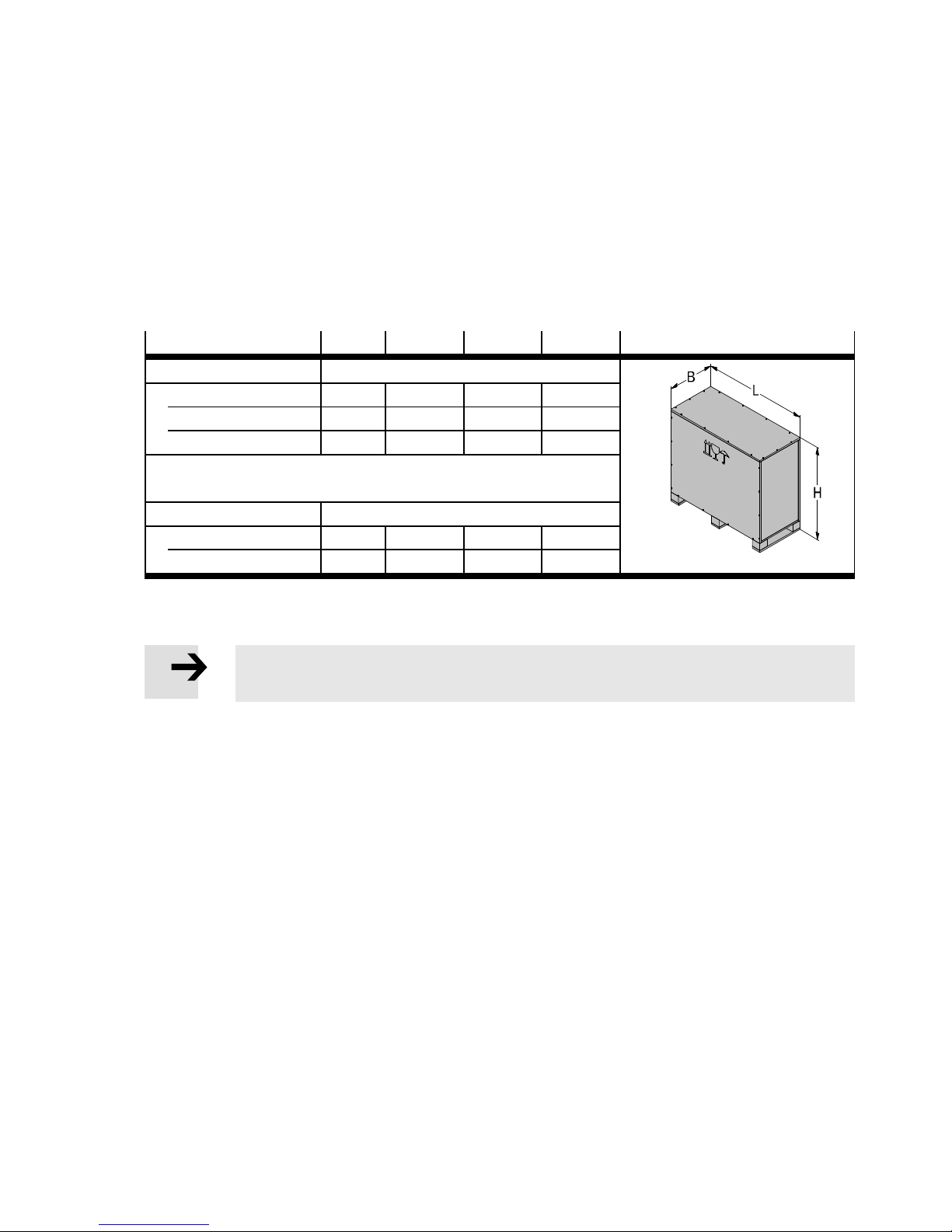
The control system is delivered on a pallet and is protected with a cover made of plates. The mounting
plate design is also screwed to the pallet.
2.1.1 Dimensions and weights
CMCA-…-B...
Dimensions [mm]
H 565 868 1018
L 1010 1140 1140
B 640 510 510
Maximum weight
Control system 43 81 91
Overall weight 87 127 144
1) Dependent on the design and accessories
Tab. 2 . 1
1. Transport the pallet with the control system to the mounting/storage location.
2. Set the pallet down on a fixed and flat base at the mounting/storage location.
1)
Note
• For transport, observe the marking on the upper side on the transport box.
[kg]
C- CC- CS-
Festo – GDCP-CMC A-B-INST-EN – 1405N H – English 7
Page 8
2 Transport and storage
2.2 Storage conditions
• For safe later use, the following storage conditions must be complied with.
Storage conditions
Storage temperature [°C] –20 … +60
Relative air humidity [%] 10 … 95 (non-condensing)
Max. storage time 60 months
Requirements of sto rage location dry, solid and flat base
Tab. 2 . 2
2.3 Unpacking
Note
Damage to the product from incorrect dismounting of the transport packaging.
• Use the correct tool to loosen the screws.
• Do not let packaging parts fall onto the control system.
• Observe product weight.( 2.1.1 Dimensions and weights).
• Keep the packaging for later use or dispose of it in accordance with the notes
( 7.3 Disposal).
8 Festo – GDCP-CMCA-B-INST-EN – 1405NH – English
Page 9
2Transportandstorage
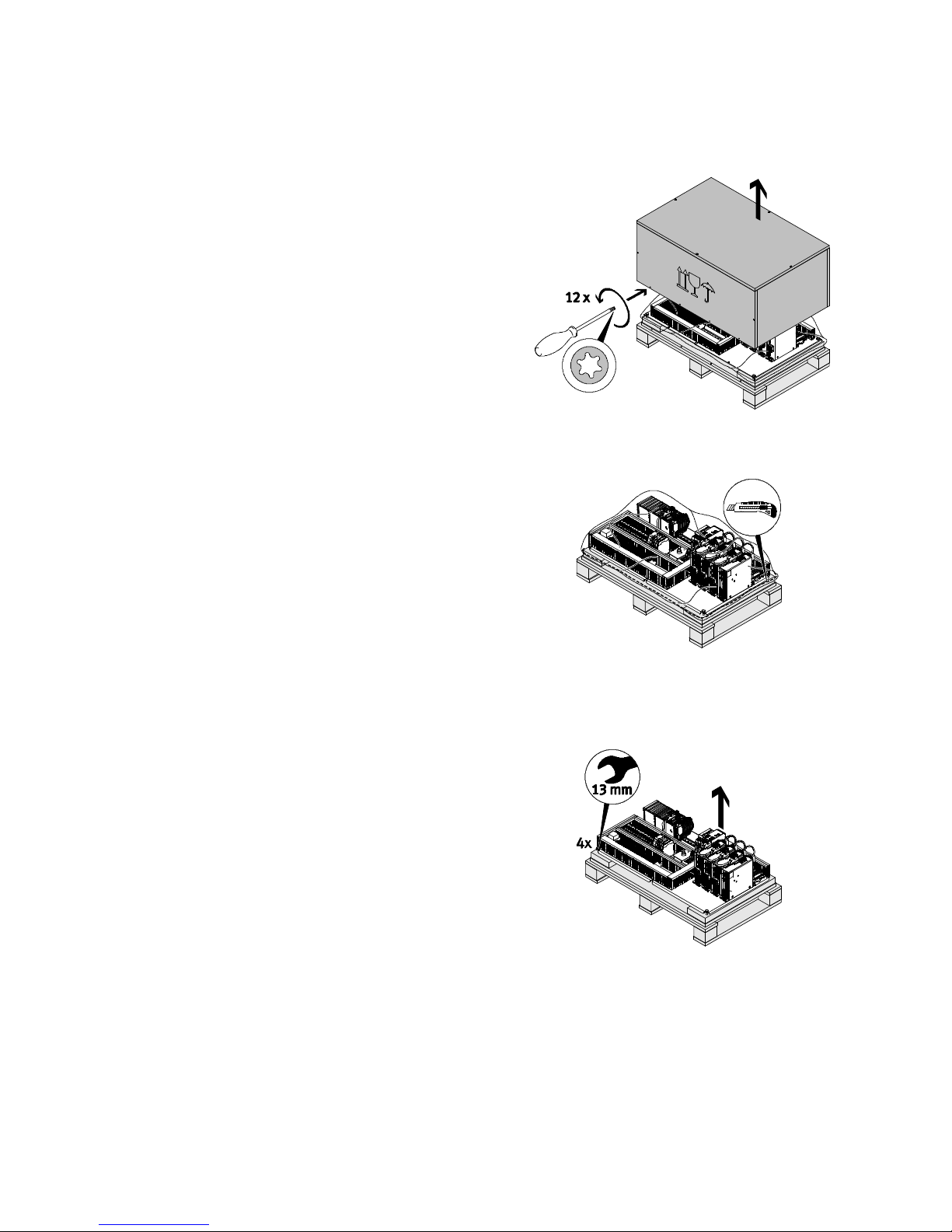
2.3.1 Mounting plate
Remove transport packaging
1. Loosen and remove the lower cover screws.
2. Pull cover off upwards.
Remove the packaging foil
3. Cut the plastic sheet parallel to the contour of
the product with an appropriate tool. When
cutting, make sure that you do not damage or
scratch the components of the control system.
4. Pull the plastic sheet upward and away. Carefully remove the bag with drying agent and dispose of it in accordance with the instructions
( 7.3 Disposal).
Fig. 2.1
Fig. 2.2
Loosen mounting plate
5. Loosen and remove the screws with which the
mounting plate is screwed to the pallet.
6. With two people, lift the control system off the
pallet and bring it to the installation site.
Festo – GDCP-CMC A-B-INST-EN – 1405N H – English 9
Fig. 2.3
Page 10
2 Transport and storage
2.3.2 Control cabinet
Warning
Danger of injury/damage due to falling loads.
The device to lift the control cabinet out of the transport packaging must be sufficiently
dimensioned.
• Observe product weight ( 2.1.1 Dimensions and weights).
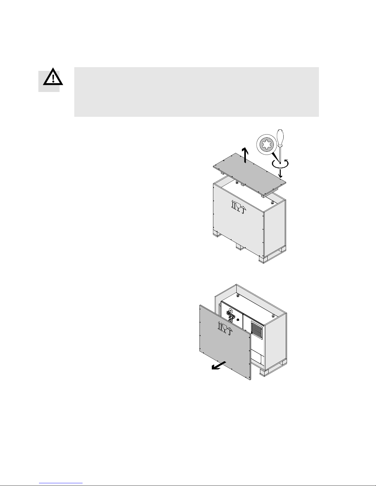
Remove transport packaging
1. Loosen and remove all screws from the cover.
2. Remove transport packaging covers upward.
3. Loosen and remove all screws of the side wall
near the c ontrol c abinet doors.
4. Pull the side wall forward and off.
Fig. 2.4
Fig. 2.5
10 Festo – GDCP-CMCA-B-INST-EN – 1405NH – English
Page 11
2Transportandstorage
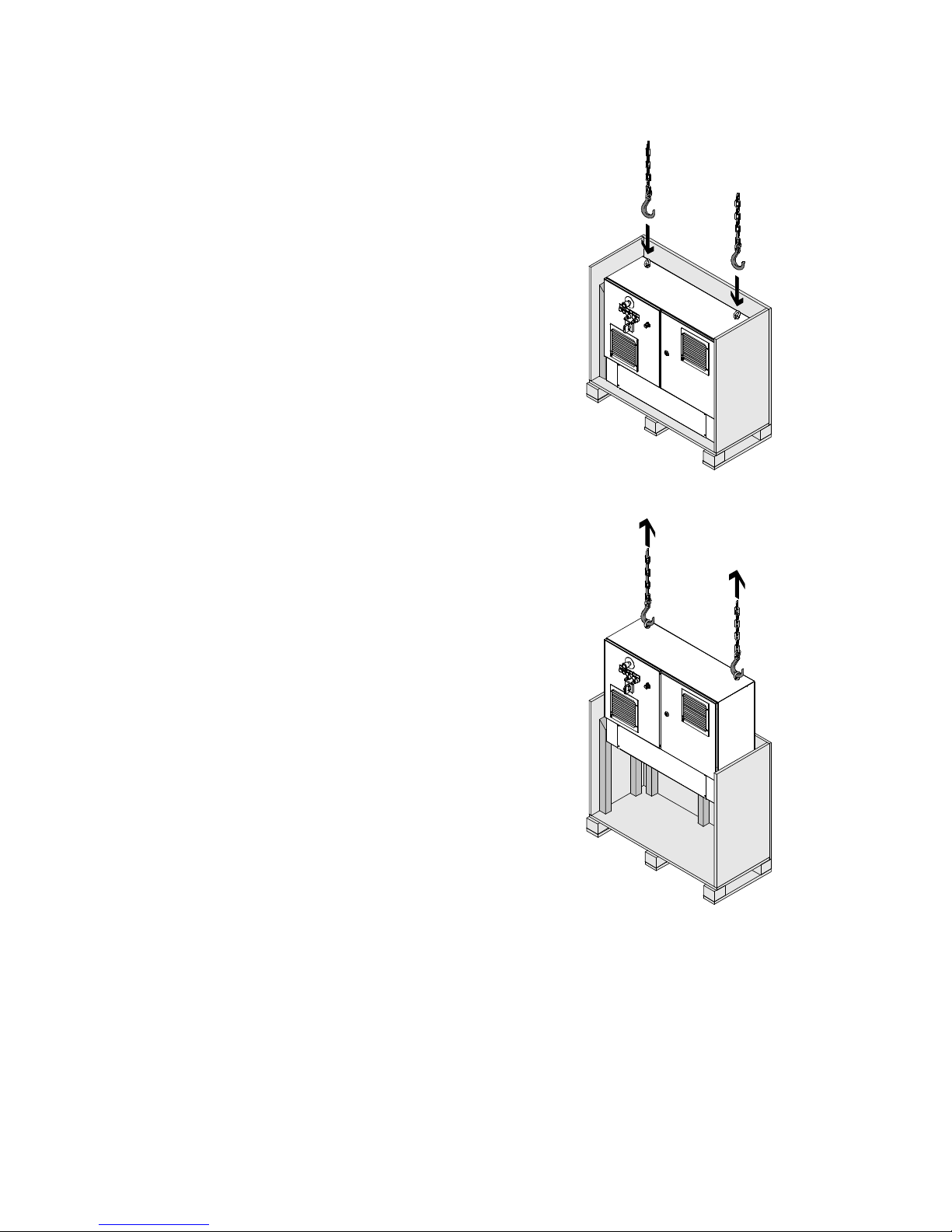
5. Mount an appropriate lifting device to the
transport lugs of the control cabinet.
6. Lift the control cabinet out of the transport
packaging.
Fig. 2.6
Festo – GDCP-CMC A-B-INST-EN – 1405N H – English 11
Fig. 2.7
Page 12
2 Transport and storage
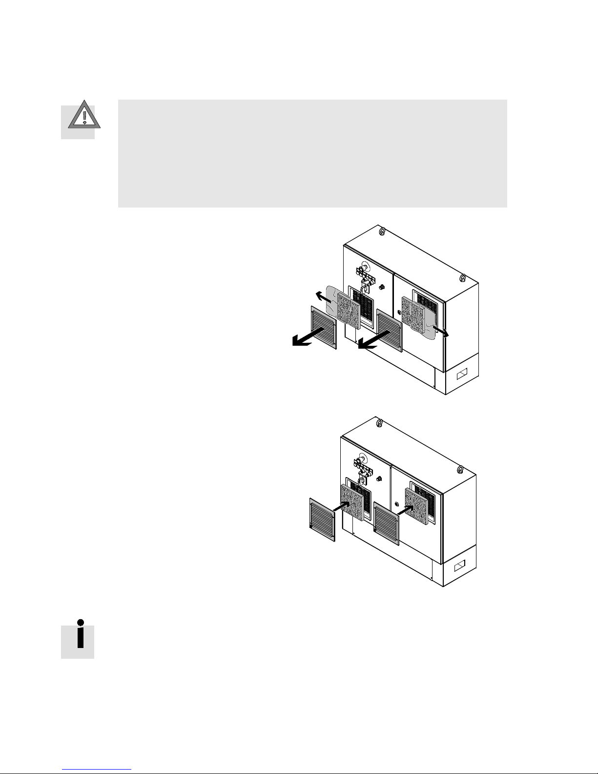
Unpack filter mats
Caution
Fire risk from overheating.
At delivery, the filter mats for control cabinet fans and outlet filters are packed in plastic
and placed in the filter cassettes.
Operation of the control system with packaged filter mats results in overheating and
related consequential damage.
• Remove the plastic packaging from both filter mats as described subsequently.
1. Pull the covers of the filter housing off to the
front.
2. Take out the packaged filter mats.
3. Remove the packaging.
4. Place the unpackaged filter mats in the filter
housing.
5. Install covers again.
Remove drying agent
The control cabinet includes several bags with drying agent to protect against damage
due to moisture.
Before installation of the control system:
• Carefully remove the drying agent from the control cabinet and dispose of it in
accordance with the instructions ( 7.3 Disposal).
Fig. 2.8
Fig. 2.9
12 Festo – GDCP-CMCA-B-INST-EN – 1405NH – English
Page 13
2Transportandstorage
2.4 Check the scope of delivery
1. After unpacking, check whether the product corresponds to the version you ordered.
2. Check accompanying user manual of the individual components for completeness.
Documentation
No.
Electrical installation control system CMCA-...-B... 1
Circuit diagram, control system CMCA-...-B... 1
Multi-axis controller CMXR-C1/CMXR-C2 1
Motor controller + CD-ROM 1
I/O module CECX-D-8E8A-NP-2 1
Power supply CACN 1
Subcon cable interface 1
Ethernet switch SFNB 1
Controller PNOZ S7 + supplement 1
Controller PNOZmulti Mini + DVD 1
Buffer module 1 (for characteristic S2)
Terminals with filter 1, 21108-2EN-04 1
Tab. 2 . 3
Only for control cabinet version:
3. Check accompanying accessories for completion.
Accessories
No.
Keyforkeyswitch 2 each
Key for control cabinet doors 1
Inscription labels for control elements, German 6
Tab. 2 . 4
Festo – GDCP-CMC A-B-INST-EN – 1405N H – English 13
Page 14
3Overview
3Overview
3.1 Function and application
The control system CMCA-...-B... serves to control and monitor a connected kinematics system with several
axes. Each axis of the kinem atics system is controlled by a motor controller. The higher-order multi-axis controller coordinates the movements of the indi v i dual axes through the correspondin g motor controll er.
3.2 Design
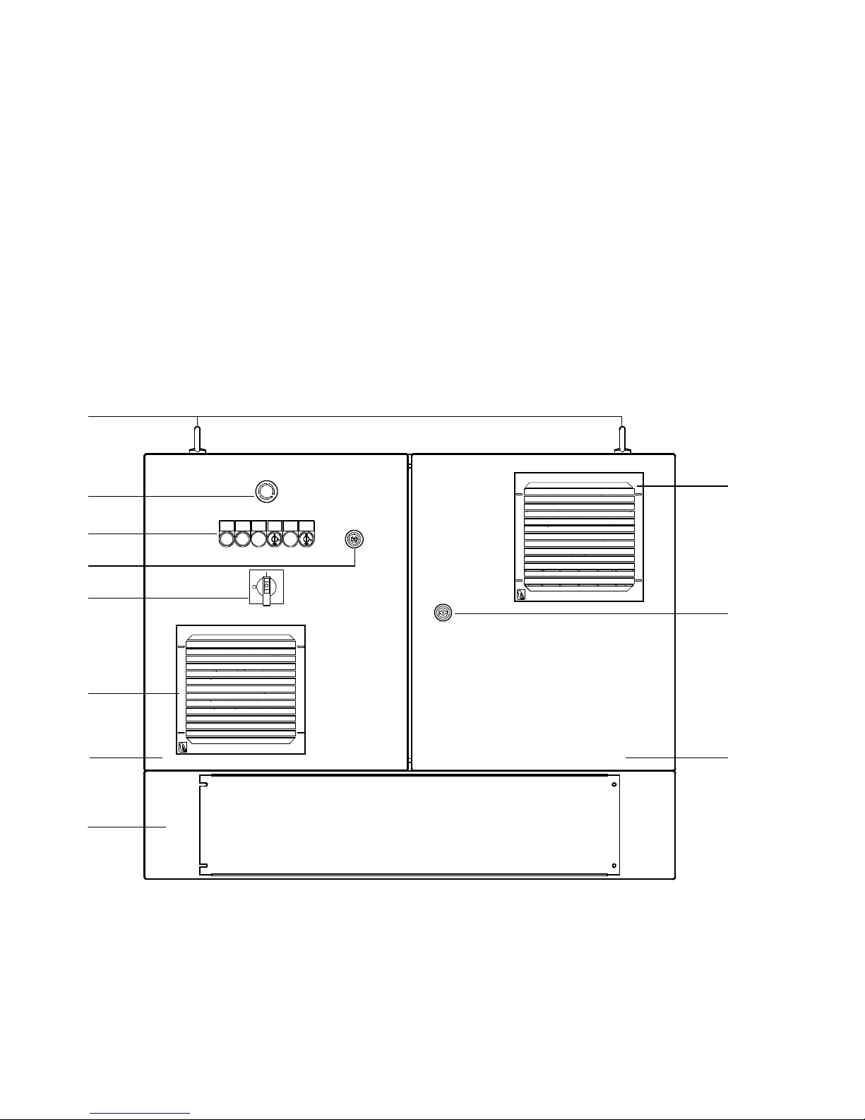
3.2.1 External c ontrol elements and connections
8
7
6
5
4
3
2
1
9
aJ
aA
1 Base (option)
2 Control cabinet door, left
3 Control cabinet fan cover
4 Power switch
5 Connection for operator unit CDSA or
enabling button CACS-Z-...
Fig. 3.1
14 Festo – GDCP-CMCA-B-I NST-EN – 1405NH – English
6 Control and signal elements ( Fig. 3.2)
7 Emergency stop switch (S1)
8 Transport lugs
9 Outlet filter cover
aJ Control cabinet doors interlock
aA Control cabinet door right
Page 15
3Overview
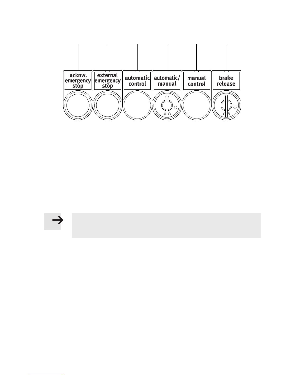
562341
1 Illuminated push-button (S20/P20) “acknowledge emergency stop”: confirms unlocking of the
emergency stop circuit
2 Indicator light (P21) “external emergency stop”: external emergenc y stop triggered
3 Indicator light (P4) “automatic control”: automatic operation active
4 Key switch (S2) “automatic/manual”: Switches between automatic and manual override
The switch is only active when the “local” operating mode has been selected by means of link
plugs ( Tab. 4.18). In case of “external” operating mode, the switch is without effect.
5 Indicator light (P5) “manual control”: manual override active
6 Key actuator (S3) “brake release”: releases the motor brakes
Only possible in manual override and in combination with one of the enabling buttons on the oper-
ator unit CDSA or the enabling button CACS-Z-....
Fig. 3.2
Note
The labels for marking the c ontrol elements in German as well are included in the control cabinet.
Festo – GDCP-CMC A-B-INST-EN – 1405N H – English 15
Page 16
3Overview
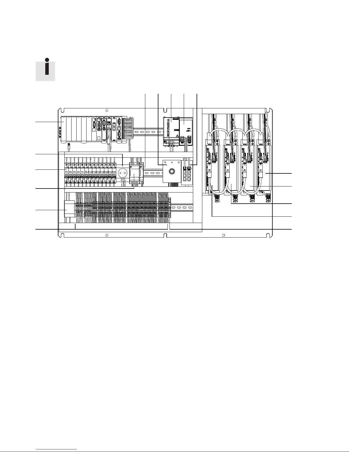
3.2.2 Internal components and connections
The design can deviate from the illustration, depending on the version.
7 8 9aJaA
6
5
4
3
2
1
1 Terminal strips X0 … X6
2 Monitoring module for mains failure detection (only for characteristic S2)
3 Controller, safety control circuit PNOZ S7
4 Circuit breakers F1 … F22
5 Protective contact socket type F (230 V AC, max. 6 A) for PC
6 Multi-axis controller
7 Controller, safety control circuit extension PNOZmulti
8 Connection for operator unit CDSA or enabling button CACS-Z-...
(with control cabinet design on the left door)
9 Buffer module 24 V DC (only for characteristic S2)
aJ Power supply unit 24 V DC
aA Ethernet switch
aB Motor controller for axis 4 (only for characteristic B3, B5, B8)
aC Motor controller for axis 3 (only for characteristic B2, B3, B4, B5, B7, B8)
aD Motor controller for axis 2
aE Motor controller for axis 1
aF Terminals with filter
Fig. 3.3
aB
aC
aD
aE
aF
16 Festo – GDCP-CMCA-B-INST-EN – 1405NH – English
Page 17
3Overview
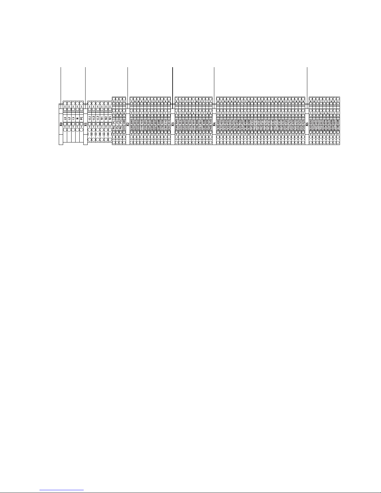
3.2.3 Terminal strips
1 X0: Feed upstream of power switch
2 X1: Feed downstream of power switch
3 X2: Control circuit 24 V DC
4 X3: Emergency stop
5 X4: External emergency stop
6 X6: Control and signal elements
Fig. 3.4
5623 41
Festo – GDCP-CMC A-B-INST-EN – 1405N H – English 17
Page 18
3Overview
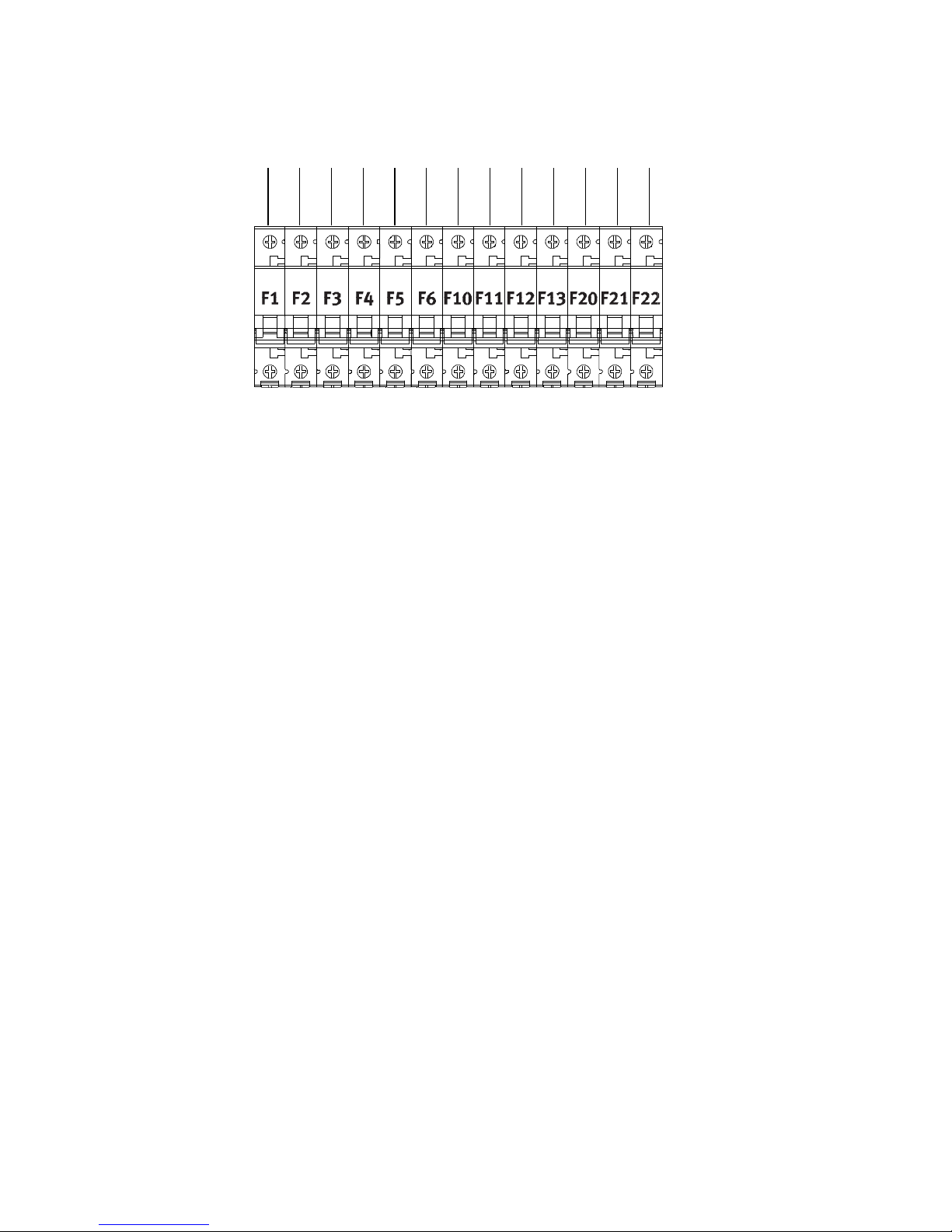
3.2.4 Circuit breakers
562341 7 8 9 aJ aA aB aC
1 F1 (B16 A):
power supply 230 V AC, power supply unit 24 V DC
2 F2 (B16 A):
power supply 230 V AC, load circuit motor controller axis 1
(three-phase for c haracteristics A6, A7 and A8)
3 F3 (B16 A):
power supply 230 V AC, load circuit motor controller axis 2
(three-phase for c haracteristics A6, A7 and A8)
4 F4 (B16 A):
power supply 230 V AC, load circuit motor controller axis 3
(only for characteristics B2, B3, B4, B5, B7, B8)
5 F5 (B16 A):
power supply 230 V AC, load circuit motor controller axis 4
(only for characteristics B3, B5, B8)
6 F6 (B6 A):
power supply 230 V AC, plug socket
7 F10 (B2 A):
power supply 230 V AC, control cabinet fan
8 F11 (B2 A):
power supply 230 V AC, control cabinet lighting
9 F12 (B4 A):
external emergency stop
aJ F13 (B4 A):
external emergency stop
aA F20 (B6 A):
power supply 24 V DC
aB F21 (B4 A):
power supply 24 V DC
aC F22 (B2 A):
power supply 24 V DC
Fig. 3.5
18 Festo – GDCP-CMCA-B-INST-EN – 1405NH – English
Page 19
4 Mounting and installation
4 Mounting and installation
4.1 Mounting
Warning
Danger of injury/damage risk due to falling loads.
If incorrectly mounted, the control system can become loose and fall.
• Observe the product weight in selec tion of the mounting surface and mounting
material ( A.1 Technical data).
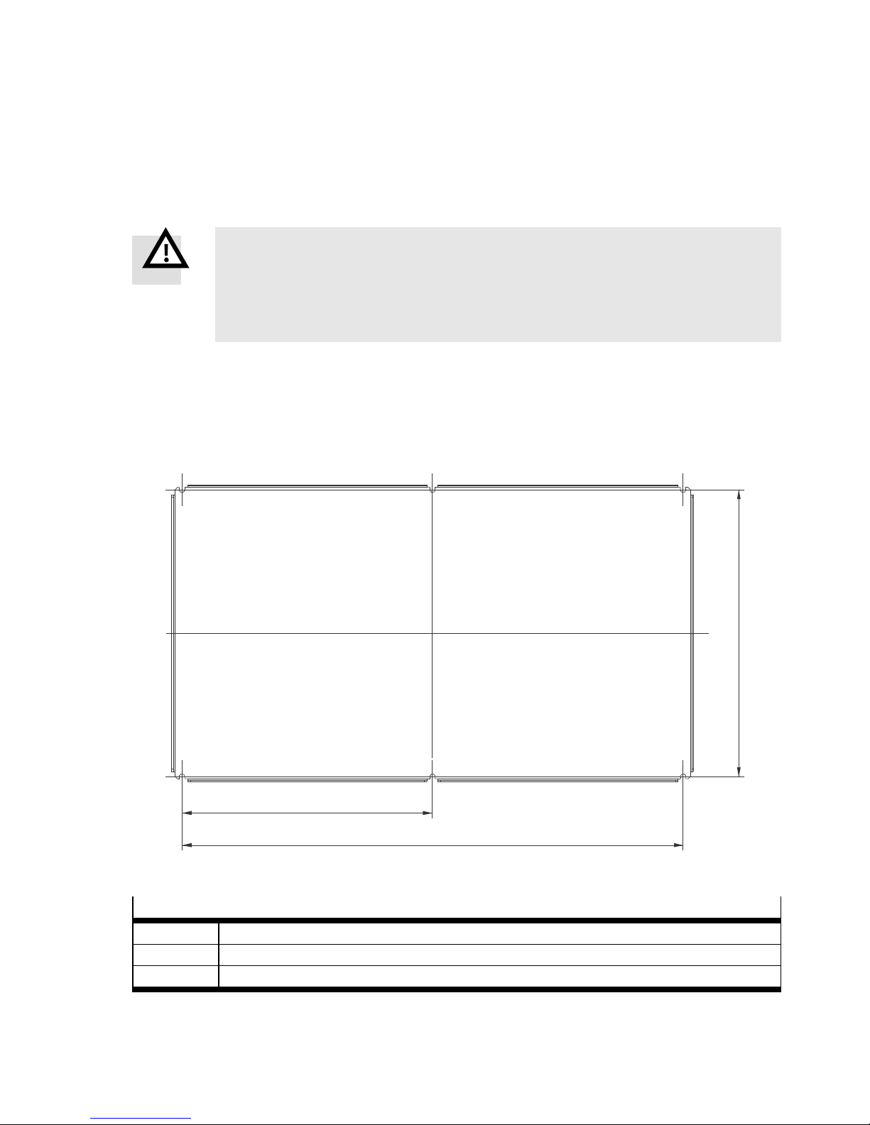
4.1.1 Mounting plate
The control system on the mounting plate must be mounted to the 6 mounting points on a vertical and
sufficiently stable surface.
Mounting points
Fig. 4.1
Dimensions [mm]
L1 925
L2 518
L3 462.5
Tab. 4. 1
L2
L3
L1
Festo – GDCP-CMC A-B-INST-EN – 1405N H – English 19
Page 20
4 Mounting and installation
4.1.2 Control cabinet without base
The control system with its own control cabinet must be mounted as follows:
– upright on a sufficiently strong wall bracket
– upright on horizontal cross braces in a frame with sufficient bearing capacity
– with a free space below the control cabinet of at least 200 mm for the cable throughfeed
Note
A wall bracket is not included in the scope of delivery.
Note
Screws and mounting accessories are not included in the scope of delivery.
• Observe the product weight in selection of the mounting surface and mounting material ( A.1 Technical data).
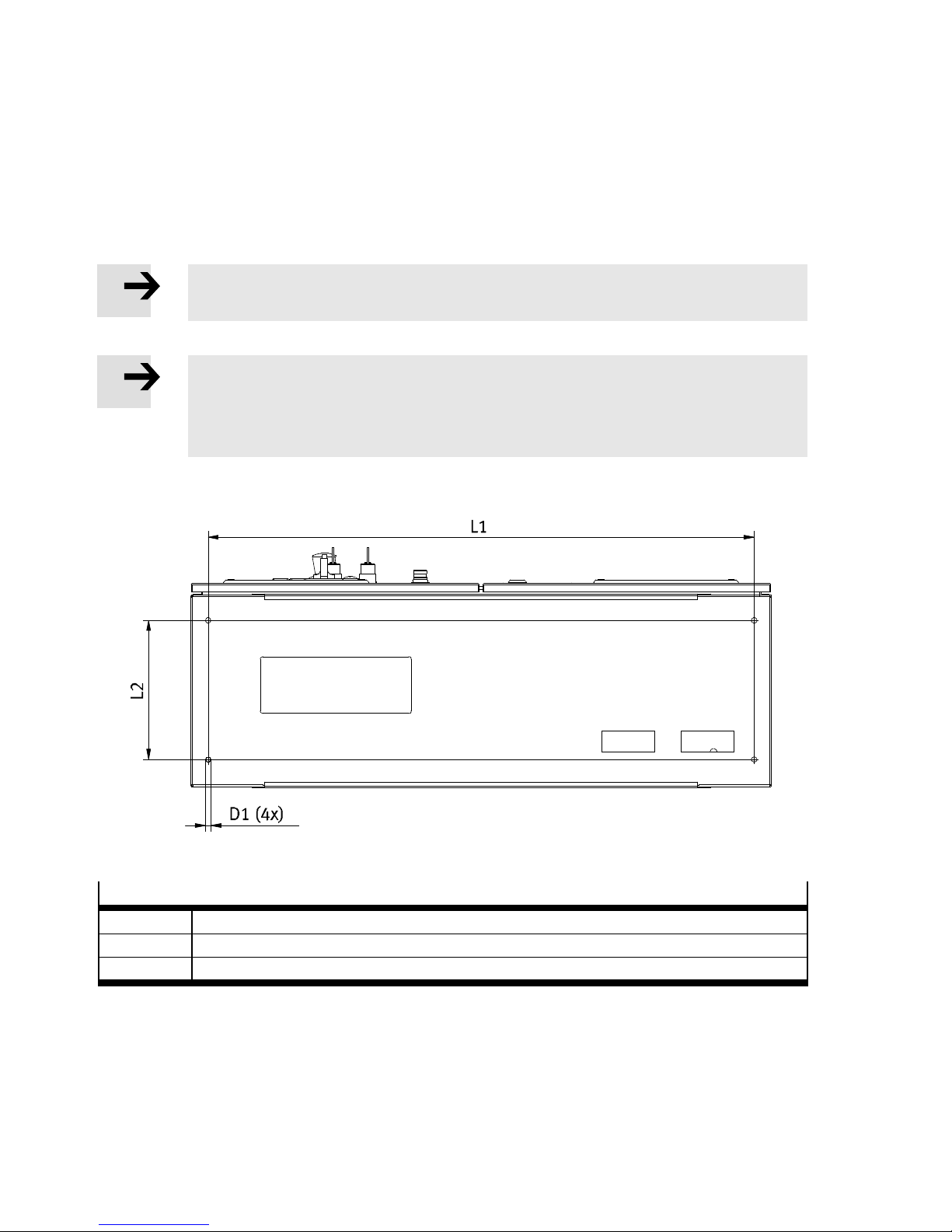
Mounting points, control cabinet bottom for mounting on wall bracket
Fig. 4.2
Dimensions [mm]
L1 940
L2 239.4
D1 ∅ 9
Tab. 4. 2
20 Festo – GDCP-CMCA-B-INST-EN – 1405NH – English
Page 21
4 Mounting and installation
4.1.3 Control cabinet with base
The control system with its own control cabinet and base must be mounted as follows:
– fastened with 4 screws through the 4 drill holes in the base on a sufficiently stable foundation
Note
Screws and mounting accessories are not included in the scope of delivery.
• Observe the product weight in selec tion of the mounting surface and mounting material ( A.1 Technical data).
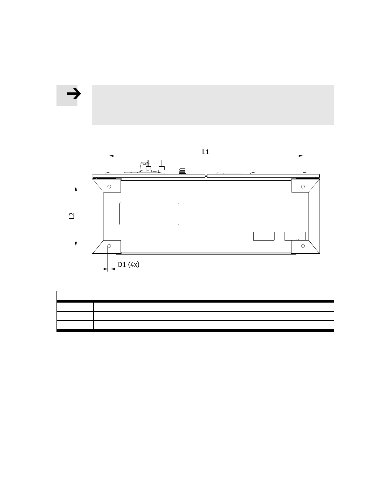
Mounting points
Fig. 4.3
Dimensions [mm]
L1 850
L2 260
D1 ∅ 14
Tab. 4. 3
Festo – GDCP-CMC A-B-INST-EN – 1405N H – English 21
Page 22
4 Mounting and installation
4.2 Electrical installation
4.2.1 Safety instructions
Warning
Danger of electric shock from voltage sources.
• Connect control system directly to the mains switch. Do not use a plug.
• Mount strain relief for supply voltage connecting cables and for motor cables.
The control system is only completely voltage-free if all supply lines have been switched
voltage-free.
Before carrying out mounting, installation and/or maintenance work:
• Switch off supply voltage and safeguard against being switched on again unintentionally.
• Switch off external voltage and safeguard against being switched on again unintentionally.
• After the supply voltage is switched off, wait at least one minute. Start work on
plugs and interfaces only when the residual voltage has fallen below 60 V.
• Use a protective conductor with a cross section ≥ 10 mm² (copper) or ≥ 16 mm²
(aluminium).
• Only use power sourc es which guarantee reliable electrical isolation of the operating
voltage in accordance with EN 60204-1.
• Connect all PE protective conduct ors before commissioning.
• Observe the regulations of E N 50178 and EN 60204-1 for protective earthing in
installation.
• S witch the voltages back on only after completion of work.
Note
The mains voltage must be protected at the mains with a maximum of 20 A (slow-blow).
Warning
Danger of injury/damage due to ineffective emergency stop.
A not-connected operator unit in reach of the user can result in ineffective use of the
emergency stop switch.
• Keep a not-connected operator unit outside the reach of the user.
22 Festo – GDCP-CMCA-B-INST-EN – 1405NH – English
Page 23
4 Mounting and installation
Caution
An active emergency stop only has an effect on the electric drives. Any pneumatic components that may be on hand are not affected.
• If necessary, plan corresponding safety equipment for the pneumatic components of
the system. For control, use the connection for external emergency stop circuits
( 4.2.6 External emergency stop circuits).
Note
The description of the electric installation in this chapter requires completely mounted
and installed kinematics ( mechanical installation description).
For operation of the control system, the following measures must be taken:
– Use screened motor connection cables ( motor c ontroller description).
– The high leakage current can cause problems if a fault current protective device is
used.
Note
Damage to the product from incorrect ha ndling.
• Never pull or plug in the plug connectors and interfaces when powered.
ESD (electrostatic discharge) can cause damage to the device or other system parts at
plug connectors that are not used.
• Observe the handling specifications for electrostatically sensitive devices.
Note
Unplugging the connection cover or a connected device triggers an emergency stop.
• Put the system at rest before the connection cover or a connected device is plugged
in or unplugged.
Either a device must be connected or the connection cover mounted. Otherwise, the
emergency stop circuit is opened (emergency stop active).
Festo – GDCP-CMC A-B-INST-EN – 1405N H – English 23
Page 24
4 Mounting and installation
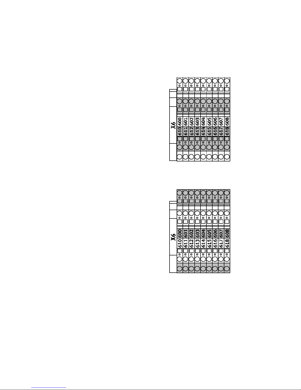
4.2.2 Design of the double-stack terminals
The double-stack terminals of the terminal strips X2 … X6 and the right par t of X1 have the following
design.
Connection number with the identification on top
The terminals on top c orrespond to the terminal
numbers, also attached somewhat further on top
(here 610 … 618).
Both connections of a terminal are bridged internally.
Fig. 4.4
Connection number with the identification underneath
The terminals below correspond to the terminal
numbers, also attached somewhat further underneath (here 600 … 608).
Both connections of a terminal are bridged internally.
Fig. 4.5
24 Festo – GDCP-CMCA-B-I NST-EN – 1405NH – English
Page 25
4 Mounting and installation
4.2.3 Supply voltage
Note
In the design with a control cabinet, guide the supply lines of the supply voltage
through the left one of the two cut-outs on the bottom of the control cabinet.
• Guide the supply line of the supply voltage (230/400 V AC / 3-phase, 50 … 60 Hz) in the cable duct
to the terminal strip X0.
• Connect the conductors to the lower clamping contacts of the terminals.
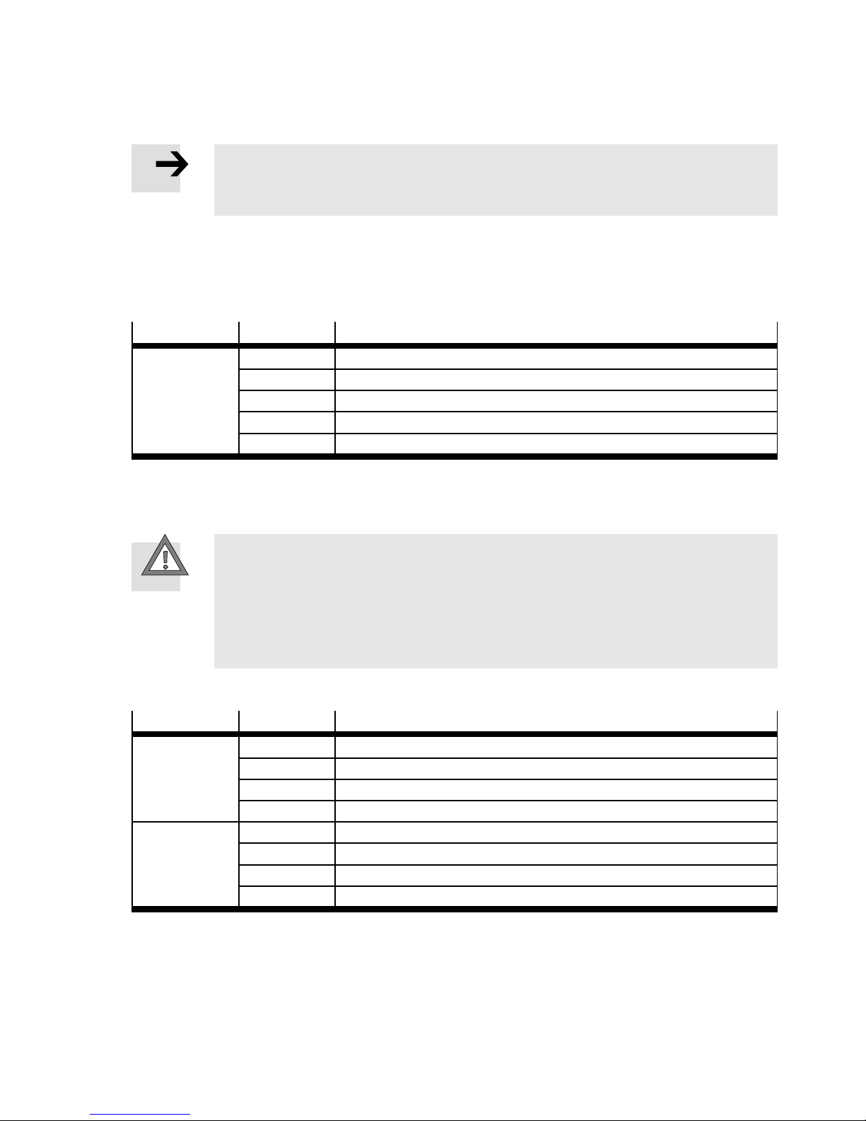
Terminal strip
Ter mi nal Description
X0 L1 External conductor L1 (phase 1)
L2 External conductor L2 (phase 2)
L3 External conductor L3 (phase 3)
N Neutral conductor
PE Protective earth conductor (connected to the mounting plate)
Tab. 4. 4
4.2.4 Power switch (mounting plate design)
Caution
Danger of damage to the motor controller.
Switching on one or more phases before switching on the neutral conductor can result
in damage to the motor controller.
• Use a 4-pin switching power switch with a leading contact at switch-on for the neutral conductor to prevent damage to the motor controllers during switch-on.
• Connect the power switch from above to the terminal strip X0 and from below to the terminal strip X1.
Terminal strip
Ter mi nal Connections, power switch
X0 L1 L1
L2 L2
L3 L3
N N
X1 1L1 T1
1L2 T2
1L3 T3
N1 N
Tab. 4. 5
Festo – GDCP-CMC A-B-INST-EN – 1405N H – English 25
Page 26
4 Mounting and installation
4.2.5 Emergency stop switch(mounting plate design)
• Connect switches for triggering the emergency stop function to the terminal strip X3.
Unlock emergency stop switch:
• Actuate “Acknowledge emergency stop” illuminated push-button.
Emergency stop control cabinet door
Note
In the control cabinet version:
– the emergency stop switch is already connected.
In the mounting plate design:
– the installer must connect the corresponding components.
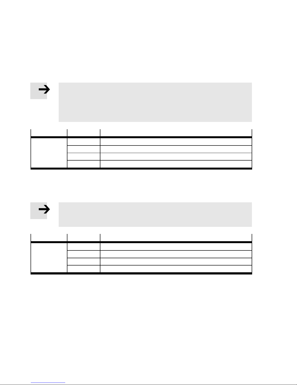
Terminal strip
Ter mi nal Emergency stop switch (S1)
X3 302 Switch 1, pin 11
330 Switch 1, pin 12
303 Switch 2, pin 21
331 Switch 2, pin 22
Tab. 4. 6
Emergency stop extension
Connection options for an additional emergency stop switch.
Note
If not used:
• Bypass terminals (300 with 330 and 301 with 331).
Terminal strip
Ter mi nal Additional emergency stop switch
X3 300 Switch 1, pin 11
330 Switch 1, pin 12
301 Switch 2, pin 21
331 Switch 2, pin 22
Tab. 4. 7
26 Festo – GDCP-CMCA-B-INST-EN – 1405NH – English
Page 27
4 Mounting and installation
External emergency stop contacts
Connection option for external potential-free contacts for triggering the emergency stop function (e.g.
from other control areas of the same complete system).
Note
If not used
• Bypass terminals (304 with 307 and 305 with 337).
• Prevent an automatic restart through a higher-order safety circuit.
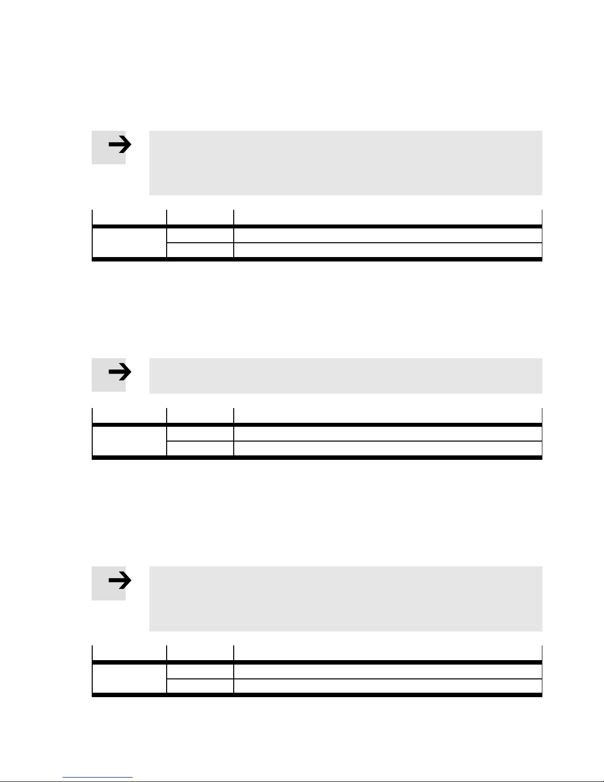
Terminal strip
Ter mi nal Description
X3 304 + 307 External emergency stop, channel 1
305 + 337 External emergency stop, channel 2
Tab. 4. 8
4.2.6 External emergency s top c irc u its
Connections for signaling an emergency stop to other control areas of the complete system:
– Two potential-free relay contacts are available.
– If an emergency stop is triggered, these relay contacts are opened.
Note
The maximum current on contact is 6 A.
Terminal strip
X4 409 + 439 External emergency stop, channel 1
1) Protected through fuse F12
2) Protected through fuse F13
Ter mi nal Description
410 + 440 External emergency stop, channel 2
1)
2)
Tab. 4. 9
4.2.7 Protective door switch
Connections for the contact switches of the safety doors.
The protective door signal can also be generated from another control circuit of the complete system.
Note
If not used:
• Bypass terminals (332 with 308 and 333 with 338).
• Prevent an automatic restart through a higher-order safety circuit.
Terminal strip
Ter mi nal Description
X3 332 + 308 Protective door switch, channel 1
333 + 338 Protective door switch, channel 2
Tab. 4. 10
Festo – GDCP-CMC A-B-INST-EN – 1405N H – English 27
Page 28
4 Mounting and installation
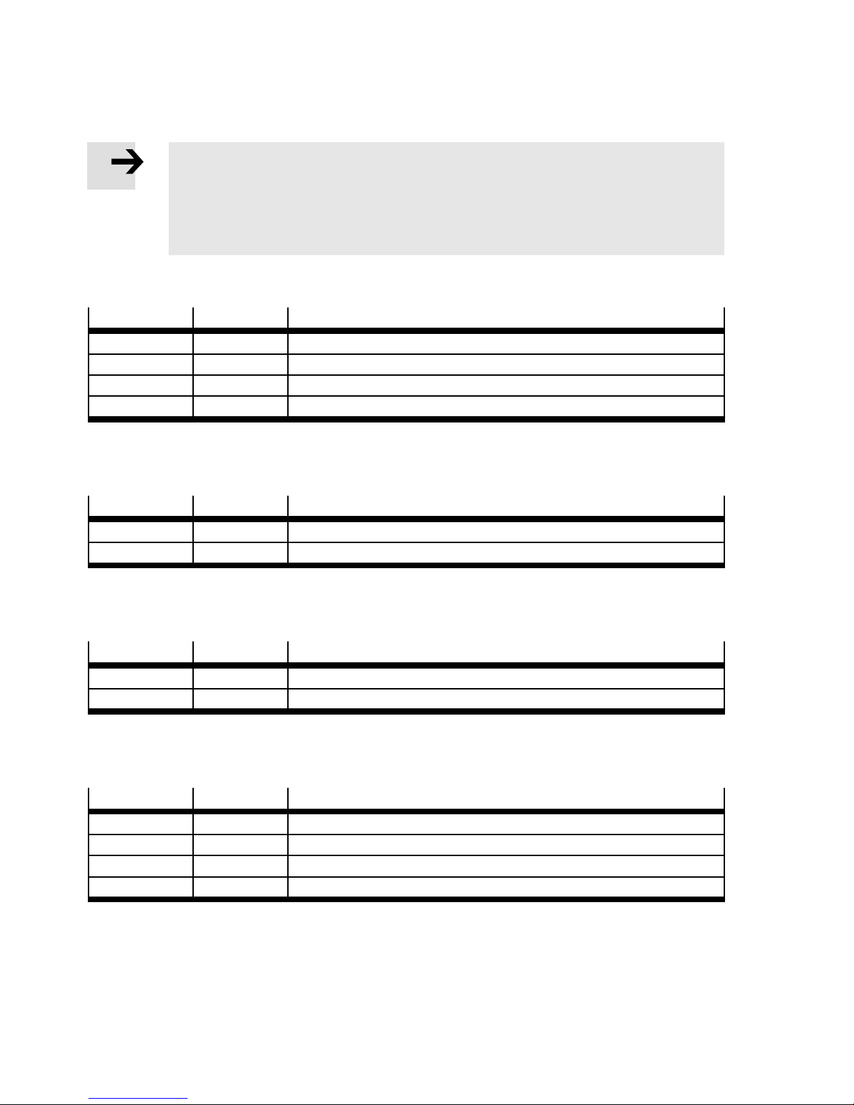
4.2.8 Control and signal elements
Note
Control cabinet version:
– The components are already connected.
Mounting plate design:
– The installer must connect the corresponding components.
Illuminated button “acknowledge emergency stop” (acknowledge emergency stop) (S20/P20)
Terminal strip
Ter mi nal Description
X3 306 Connection 13, (S20)
X6 600 Connection 14, (S20)
X2 207 0 V DC, (P20)
X6 601 +24 V DC, (P20)
Tab. 4. 11
Indicator light “external emergency stop” (external emergency stop triggered) (P21)
Terminal strip
Ter mi nal Description
X2 210 0 V DC, (P21)
X6 602 +24 V DC, (P21)
Tab. 4. 12
Indicator light “automatic control” (automatic operation active) (P4)
Terminal strip
Ter mi nal Description
X2 204 0 V DC, (P4)
X6 616 +24 V DC, (P4)
Tab. 4. 13
Key switch “automatic/manual” (automatic/manual) local (S2)
Terminal strip
Ter mi nal Description
X3 337 Pin 11, (S2)
X6 615 Pin 12, (S2)
X3 307 Pin 13, (S2)
X6 612 Pin 14, (S2)
Tab. 4. 14
28 Festo – GDCP-CMCA-B-INST-EN – 1405NH – English
Page 29
4 Mounting and installation
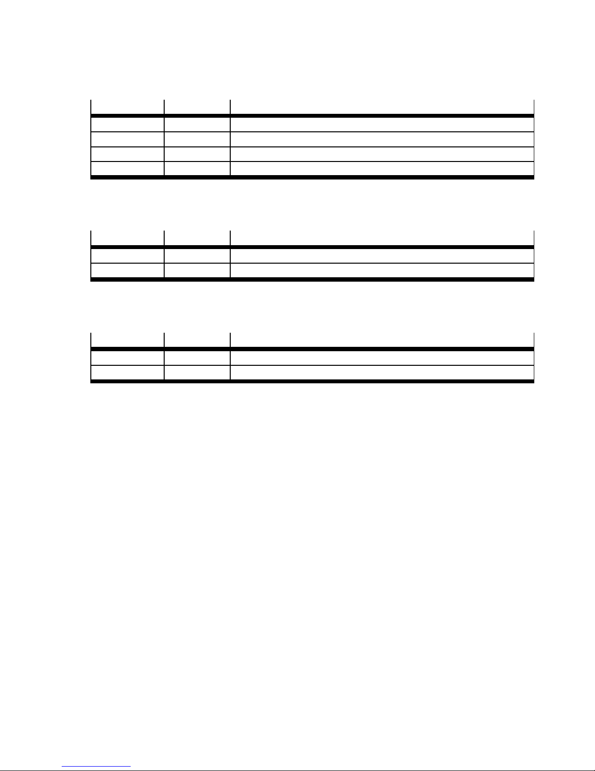
Additional key switch “automatic/manual” external (S21)
Terminal strip
Ter mi nal Description
X3 340 Pin 11, (S21)
X6 613 Pin 12, (S21)
X3 310 Pin 13, (S21)
X6 610 Pin 14, (S21)
Tab. 4. 15
Indicator light “manual control” (manual active) (P5)
Terminal strip
Ter mi nal Description
X2 206 0VDC,(P5)
X6 617 +24 V DC, (P5)
Tab. 4. 16
Key switch “brake release” (release br ake) (S3)
Terminal strip
Ter mi nal Description
X3 308 Pin 13, (S3)
X6 618 Pin 14, (S3)
Tab. 4. 17
Festo – GDCP-CMC A-B-INST-EN – 1405N H – English 29
Page 30
4 Mounting and installation
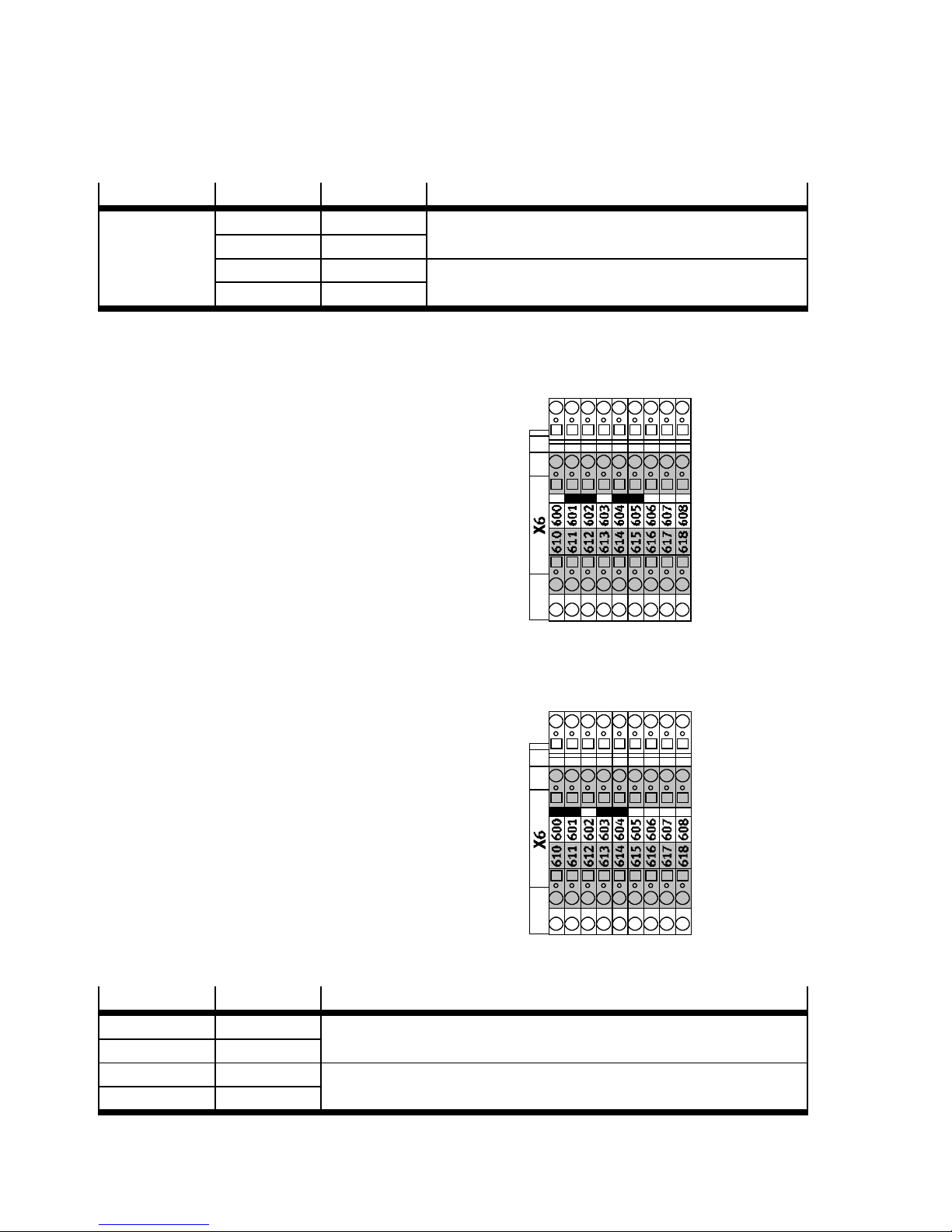
4.2.9 Mode selector
By means of jumpers, selection can be made between local and external mode selector.
Terminal strip
Ter mi nal Ter mi nal Description
X6 611 612 Mode selection local: Fig. 4.6
614 615
(delivery status)
611 610 Mode selection external: Fig. 4.7
614 613
Tab. 4. 18
Mode selection local (delivery status)
With the local key switch (S2), you can switch
between the manual override and automatic operation operating modes.
Fig. 4.6
Operating mode selection, external
With the external higher-order controller, you can
shift locally between the manual override and
automatic operation operating modes.
For external shifting:
• Make two potential-free relay contacts available. Ta b . 4 .19
Terminal strip
Ter mi nal Description
X3 310 Manual override
X6 610
X3 340 Automatic operation
X6 613
Tab. 4. 19
Fig. 4.7
30 Festo – GDCP-CMCA-B-INST-EN – 1405NH – English
Page 31
4 Mounting and installation
4.2.10 Kinematic drives
Note
In the control cabinet design, the motor and encoder cables are guided through the
right one of the two cut-outs on the bottom of the control cabinet.
• Connect the axis drives corresponding to the accompanying motor controller description.
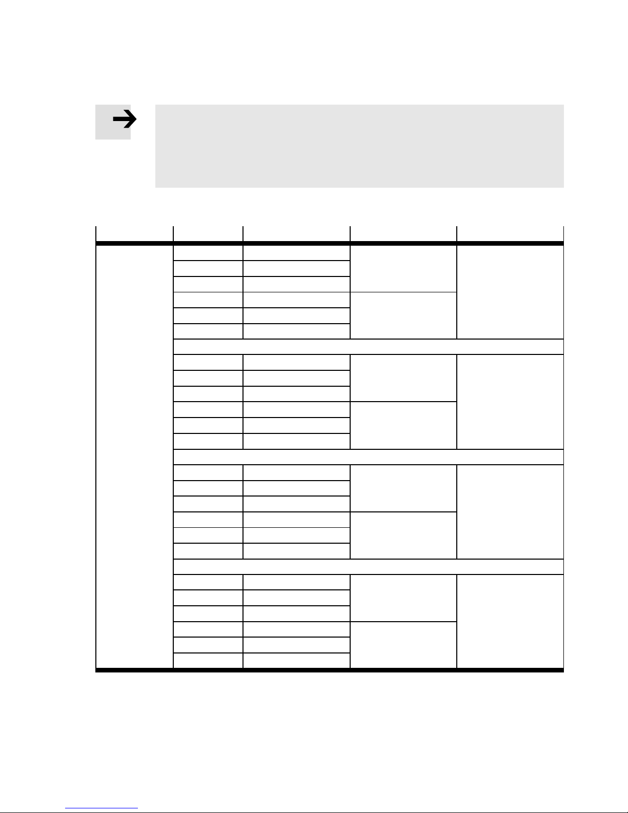
4.2.11 Connect limit switches
Terminal strip
Ter mi nal Description Limit switch Axis
X4 411 +24 V DC 1 1
441 0VDC
416 Signal output
412 +24 V DC 2
442 0VDC
417 Signal output
413 +24 V DC 1 2
443 0VDC
418 Signal output
414 +24 V DC 2
444 0VDC
419 Signal output
411 +24 V DC 1 3
441 0VDC
446 Signal output
412 +24 V DC 2
442 0VDC
447 Signal output
Only with
characteristic
B2, B3, B4,
B5, B7, B8
413 +24 V DC 1 4
443 0VDC
448 Signal output
414 +24 V DC 2
444 0VDC
449 Signal output
Tab. 4. 20
Festo – GDCP-CMC A-B-INST-EN – 1405N H – English 31
Only with
characteristic
B3, B5, B8
Page 32
4 Mounting and installation
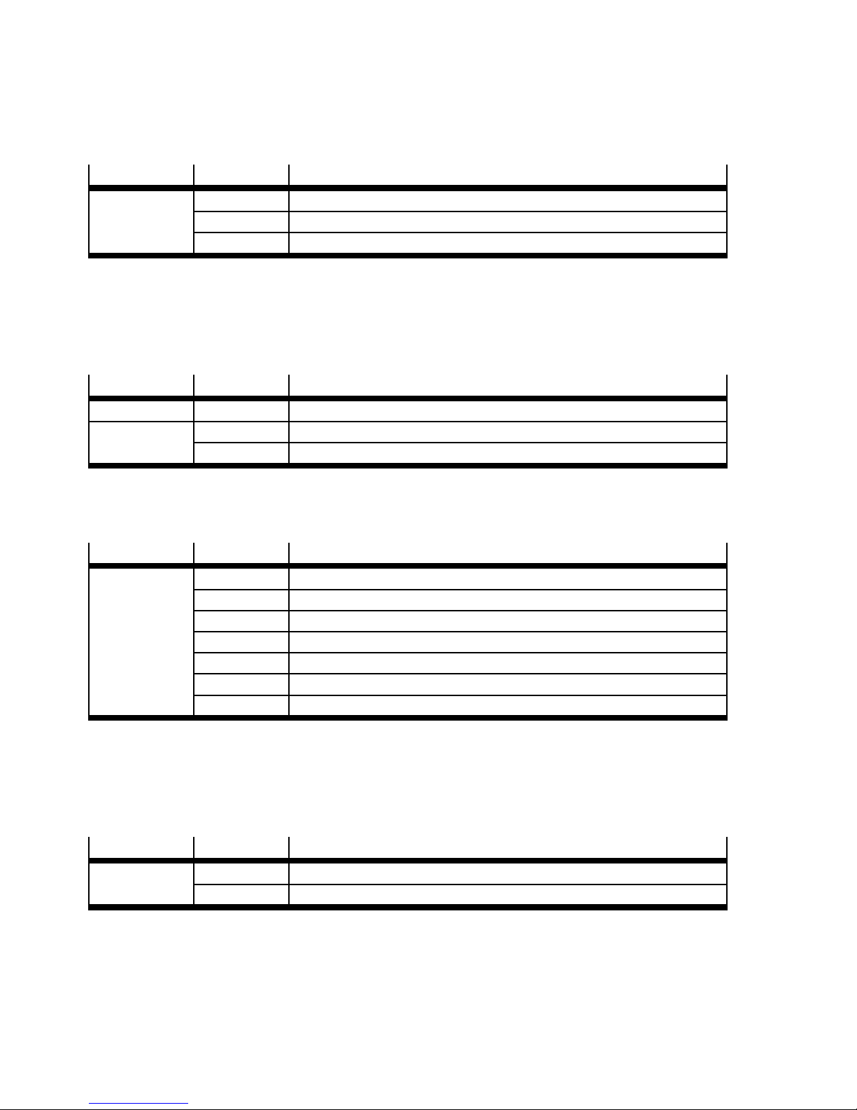
4.2.12 Rod loss detection (only for parallel kinematic system EXPT)
• Connect pressure switch SDE5 for rod loss detection as described subsequently.
Terminal strip
Ter mi nal Description
X2 208 Power supply 0 V DC
228 Power supply +24 V DC
231 Signal from the pressure switch for rod loss detection
Tab. 4. 21
• Set and adjust of the rod loss detection ( commissioning description).
4.2.13 Axis of rotation reference s ensor
• Connect the optional axis of rotation reference sensor as described subsequently.
Terminal strip
Ter mi nal Description
X4 455 Reference sensor signal (at DIN9 motor controller of the last axis)
X2 205 Power supply 0 V DC
225 Power supply +24 V DC
Tab. 4. 22
4.2.14 Camera system
Terminal strip
Ter mi nal Description
X4 415 Power supply 0 V DC
445 Power supply +24 V DC
406 Freely usable
407 Freely usable
408 Freely usable
436 Freely usable
437 Freely usable
Tab. 4. 23
4.2.15 Lighting
• Connect the power supply of an illumination device (230 V AC), e.g. for the camera system, as described below.
Terminal strip
Ter mi nal Description
X1 101 230 V AC
N3 0VAC
1) Protected through fuse F11
Tab. 4. 24
32 Festo – GDCP-CMCA-B-INST-EN – 1405NH – English
1)
Page 33
4 Mounting and installation
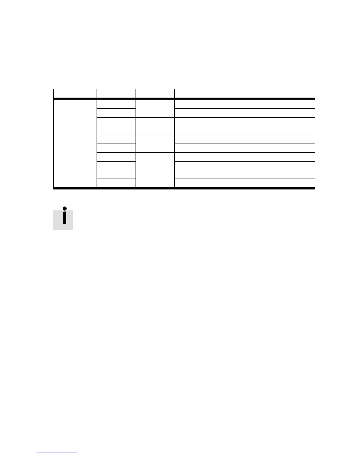
4.2.16 Freely usable outputs
The unused outputs of the I/O module CECX-D-8E8A-NP-2 at th e CMXR controller can be used for their
own extensions. The following connections are available.
Outputs
Terminal strip
Ter mi nal CECX Description
X4 401 DOX+1 Output
431 0VDC
402 DOX+4 Output
432 0VDC
403 DOX+5 Output
433 0VDC
404 DOX+6 Output
434 0VDC
405 DOX+7 Output
435 0VDC
Tab. 4. 25
For detailed information and technical data:
accompanying documentation on the I/O module CECX-D-8E8A-NP-2.
Festo – GDCP-CMC A-B-INST-EN – 1405N H – English 33
Page 34
4 Mounting and installation
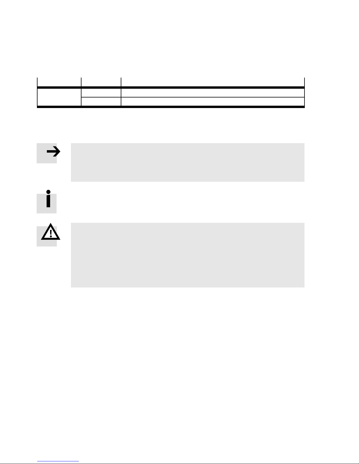
4.2.17 Additional peripheral modules for the multi-axis controller
There is the possibility to install additional peripheral modules. These can be connected to the internal
power supply.
Terminal strip
Ter mi nal Description
X2 201 0VDC
221 +24 V DC
Tab. 4. 26
For available modules sales documentation of the multi-axis controller.
Installation instructions accompany the modules.
Note
Additional modules:
– not included in delivery.
• include in the respective machine documentation
If the additional power requirement exceeds the value of 1.5 A:
• Supply external modules externally with 24 V.
Warning
Power supply unit defective. Supply voltage pushes through on the secondary page.
Injury (death) due to electric voltage.
• Use power supply unit with secure electrical disconnection of the operating voltage
in accordance with EN 60204-1.
• Observe the requirements for PELV power circuits in accordance with
IEC/DIN EN 60204-1.
34 Festo – GDCP-CMCA-B-I NST-EN – 1405NH – English
Page 35
5 Commissioning
5 Commissioning
Note
Commissioning should only be carried out by specially trained personnel. The following
knowledge is required:
– knowledge of the Festo Configuration Tool (FCT)
– knowledge of robot technology
– Codesys knowledge (only with characteristic C2)
– knowledge of the handling of the Festo components CMMP and CMXR
– knowledge of handling and operation of the kinematics to be operated
Commissioning is described in separate documents.
For support:
• Contact your regional Festo contact person.
For additional information ( www.festo.com).
Warning
Uncontrolled movement by switching on the po w er supply or incorrect actuation of the
enabling button on the operator unit CDSA or the enabling button CACS-Z-....
Injury due to electric shock, impact, squeezing.
• Before commissioning, take corresponding safeguarding measures, in order to fulfil
fundamental safety and health protection requirements.
• Perform commissioning only with knowledge of the related documents.
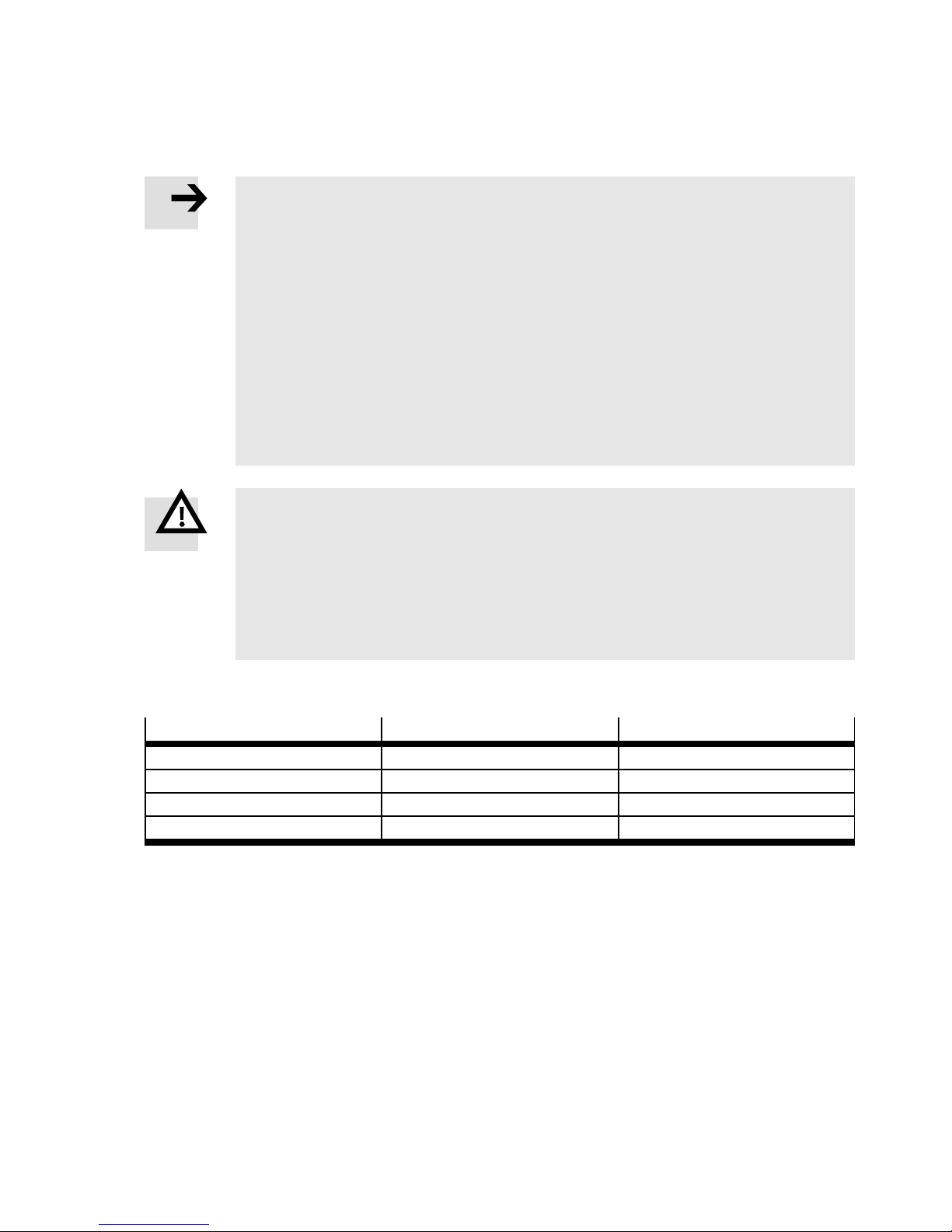
5.1 Checks before commissioning
Check
Possible malfunction Remedy
Circuit breakers triggered close
Ethernet cable unplugged plug in
CMXR memory card not completely plugged in plug in completely
Component damaged replace
1) www.festo.com/spareparts
2) 7 Module replacement and repair
1) 2)
Tab. 5 . 1
Festo – GDCP-CMC A-B-INST-EN – 1405N H – English 35
Page 36
6 Operation and diagnostics
6 Operation and diagnostics
6.1 Operation
Note
The instructions for operation must be c reated by the system manufacturer. The operator must be instructed in handling the system using the description and must have access to it at all times.
6.2 Maintenance and care
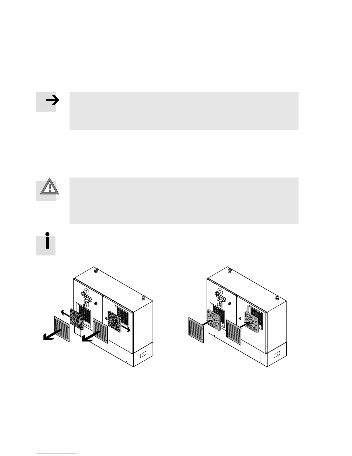
6.2.1 Control cabinet fan
Caution
Fire risk from overheating.
Filter mats of the control cabinet fan and the outlet filter:
• Check regularly for contamination (daily in dusty environments).
• Replace if necessary.
Procurement of filter mats Rübsamen & Herr company.
Type AM 435P (216 x 216 mm, filter class G3)
Fig. 6.1 Fig. 6.2
1. Pull the covers of the filter housing off to the
front.
2. Replace the dirty filter mats and dispose of
them in accordance with the instructions
( 7.3 Disposal).
3. Remove the packaging of the new filter mats.
4. Put new filter mats in place
5. Install covers.
36 Festo – GDCP-CMCA-B-INST-EN – 1405NH – English
Page 37
7 Module replacement and repair
7 Module replacement and repair
Caution
Squeezing of body parts and damage to the system.
Unintended switch-on can trigger unexpected movements.
During modification and servicing work:
• S hut down the system safely and secure it from being switched on again unintentionally.
Detached parts could fall or execute unexpected movements.
• Secure the parts against accidental movement or bring them into a safe end position.
7.1 Module replacement
Note
Replacement work may only be performed by professional personnel with the corresponding qualifications and knowledge in handling Festo components.
Note
Replacement of control components (robotics control and/or motor controller) results
in loss of parameterisation and thus operating status.
• After replacement of these components, they must be newly parameterised.
7.2 Repair
The control system does not include any repairable components.
• Replace defective components ( www.festo.com/spareparts).
7.3 Disposal
• Observe notes on dismantling parts ( 7.1 Module replacement).
The product is RoHS-compliant.
Modules and packaging material:
• Observe regulations for environmentally friendly disposal.
Festo – GDCP-CMC A-B-INST-EN – 1405N H – English 37
Page 38
A Technical appendix
A Technical appendix
A.1 Technical data
Note
For the individual components, the technical data specified in the corresponding accompanying documentation apply.
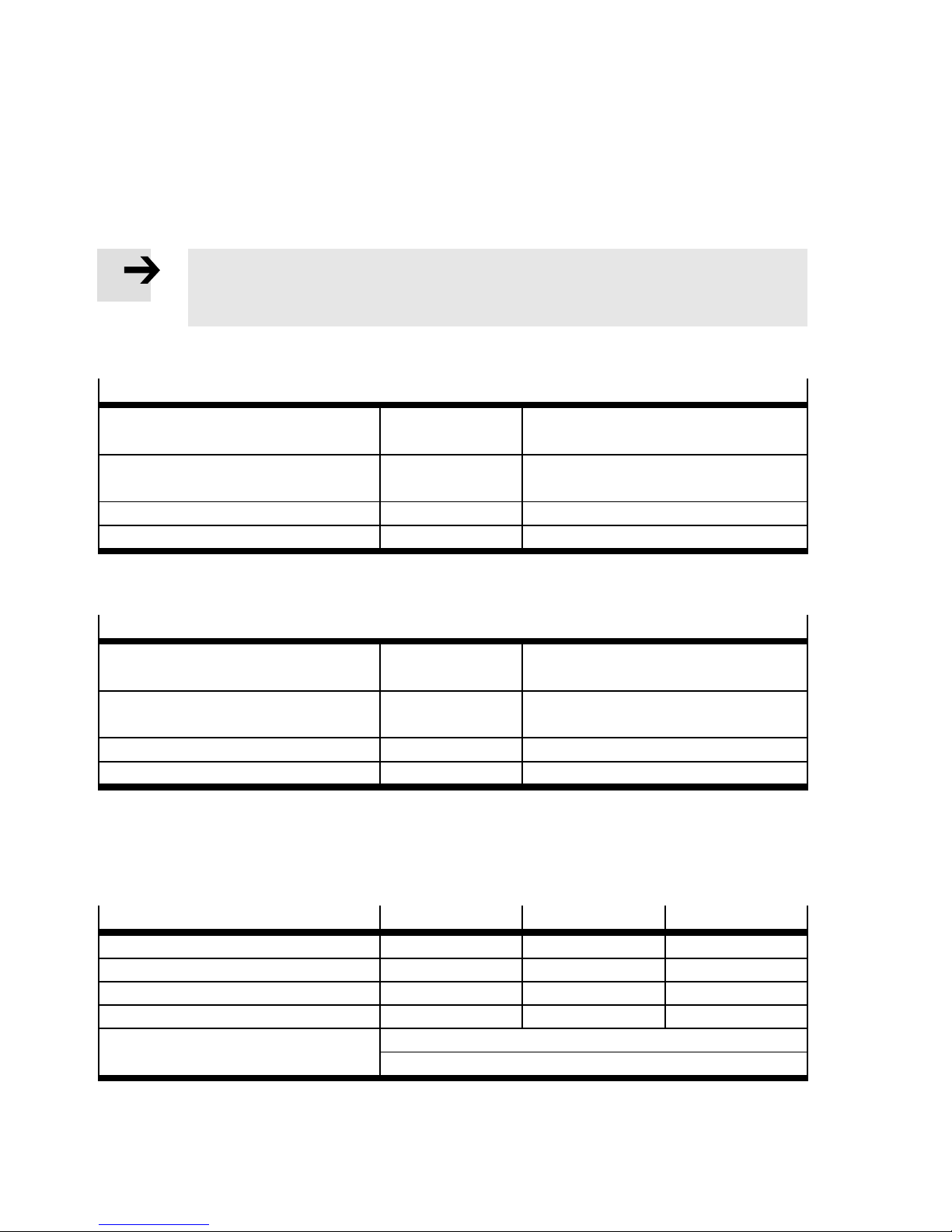
A.1.1 Safety engineering
Safety reference data CMCA-...-B...-CC-/-CS-
Safety function SS1 Safe stop 1 in accordance with
Category 4 Classification in accordance with
Performance level PL e in accordance with EN ISO 13849-1
PFHdvalue 2.34*10-8h
1)
EN 61800-5-2
EN IS O 13849-1
-1
1) If an external EMERGENCY-STOP button is integrated, its safety-engineering characteristic values must be observed.
Tab. A . 1
Safety reference data CMCA-...-B...-C-
1)2)
Safety function SS1 Safe stop 1 in accordance with
EN 61800-5-2
Category 4 Classification in accordance with
EN IS O 13849-1
Performance level PL e in accordance with EN ISO 13849-1
PFHdvalue 2.88*10-8h
1) If an external EMERGENCY-STOP button is integrated, its safety-engineering characteristic values must be observed.
2) The complete declaration of value must take into account the characteristic values for the EMERGENCY-STOP button.
-1
Tab. A . 2
A.1.2 General
Mechanical
CMCA-...-B...-C- CMCA-...-B...-CC- CMCA-...-B...-CS-
Width [mm] 962 1000 1000
Height [mm] 548 600 800
Depth [mm] 275 … 310
Maximum weight
1)
[kg] 43 81 91
1)
350 350
Note on materials Includes paint-wetting impairment substances (PWIS)
RoHS-compliant,
2)
1) Dependent on the version
2) Paint-wetting impairment substances
Tab. A . 3
38 Festo – GDCP-CMCA-B-INST-EN – 1405NH – English
Page 39
A Technical appendix
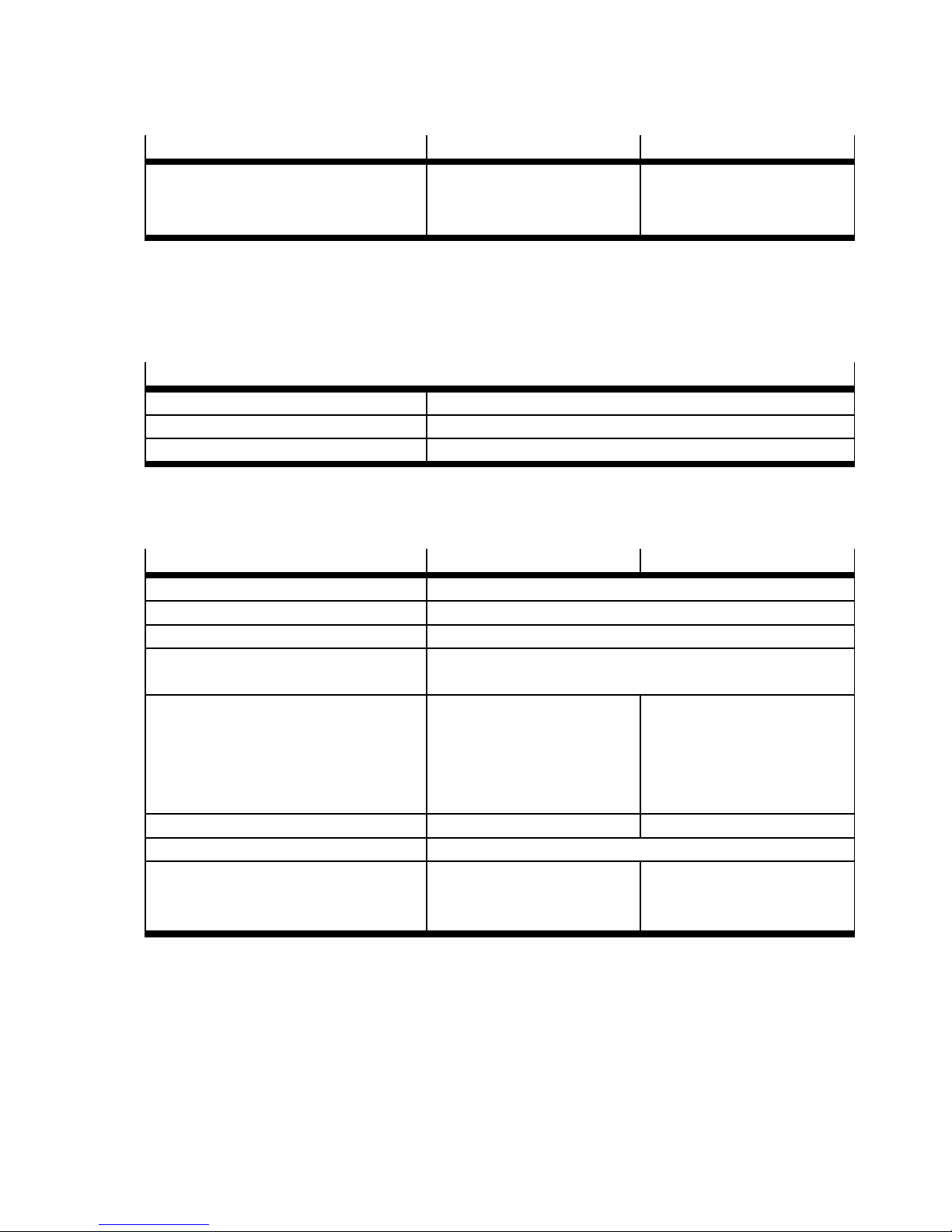
Approval certificates CMCA-...-B...-C- CMCA-...-B...-CC-/-CS-
CE marking (see declaration of
conformity)
– –EUEMCdirective
– EU low voltage directive
( www.festo.com/sp)
1) The device is intended for use in an industrial environment.
Measures for interference suppression may need to be implemented in residential areas.
Tab. A . 4
A.1.3 Electrical data
Power supply
Mains voltage [V AC] 230/400 / 3-phase
Mains frequency [Hz] 50 … 60
Fuse protection on mains side [A] max. 20 (slow-blow)
Tab. A . 5
1)
A.1.4 Operating and environmental conditions
CMCA-...-B...-C- CMCA-...-B...-CC-/-CS-
Ambient temperature [°C] +5 … +40 (outside the housing)
Storage temperature [°C] -20 … +60
Relative air humidity [%] 10 … 95 (non-condensing)
Permissible setup altitude
above sea level
Cooling About the ambient
[m] ≤ 1000
1000 … 2000 with output reduction of 10 %/1000 m
atmosphere.
If installed in a control
About the ambient
atmosphere and control
cabinet fan.
cabinet, ventilation must be
planned.
Degree of protection IP20 IP54
Relative air humidity [%] 10 … 95 (non-condensing)
Degree of contamination in
1)
2
2
accordance with
EN 61800-5-1
1) The integrated safety-engineering equipment requires compliance with degree of contamination 2 and thus a protected fitting
space. This must be ensured through corresponding measures, e.g. through installation in an appropriate control cabinet.
Tab. A . 6
Festo – GDCP-CMC A-B-INST-EN – 1405N H – English 39
Page 40

Reproduction, distribution or sale of this document or communication of its contents to others without express authorization is
prohibited. Offenders will be liable for damages. All rights reserved in the event that a patent, utility model or design patent is
registered.
Copyright:
Festo AG & Co. KG
Postfach
73726 Esslingen
Germany
Phone:
+49 711 347-0
Fax:
+49 711 347-2144
e-mail:
[email protected]
Internet:
www.festo.com
Original: de
 Loading...