

Page 1
Valve terminal CDVI
Description
of CDVI pneumatics
Valve terminal
type 15
Clean Design
Type: CDVI5.0...
Description
197363
en 1202e
[762312]
Page 2

Page 3

Contents and general safety instructions
Original de.......................................
Edition en 1202e..................................
Designation P.BE-CDVI-EN...........................
Order-no. 197363..................................
© (Festo AG & Co. KG, D-73726 Esslingen,
Federal Republic of Germany, 2012)
Internet: http://www .festo.com
E-mail: [email protected]
The copying, distribution and utilization of this document as
well as the communication of its contents to others without
expressed authorization is prohibited. Offenders shall be
held liable for payment of damages. All rights are reserved,
in particular the right to carry out patent, registered design
or ornamental design registration.
Festo P.BE-CDVI-EN en 1202e
I
Page 4

Contents and general safety instructions
II
Festo P.BE-CDVI-E N en 1202e
Page 5

Contents and general safety instructions
Contents
Intended use V......................................................
Target gr ou p VI......................................................
Service VI...........................................................
Notesontheuseofthismanual VII.......................................
Important user instructions IX..........................................
Abbreviations XI.....................................................
1. Overview of components 1-1........................................
1.1 The Clean Design valve terminal (CDVI) from Festo 1-4....................
1.2 Description of variants 1-5...........................................
1.3 Description of components 1-6.......................................
1.3.1 In-line valve manifolds 1-7...................................
1.3.2 End plates 1-9.............................................
1.3.3 Valves 1-10.................................................
1.3.4 Connection, display and control elements 1-12....................
2. Assembly 2-1.....................................................
2.1 Mounting the valve terminal 2-4......................................
2.1.1 Wall mounting 2-5..........................................
3. Installation 3-1...................................................
3.1 Compressed air preparation 3-4......................................
3.1.1 Operation with unlubricated compressed air 3-4.................
3.1.2 Operation with lubricated compressed air 3-5....................
3.2 General instructions on installation 3-7................................
3.3 Laying the tubing 3- 8...............................................
3.4 Notes on installing the CDVI 3-10......................................
3.4.1 Pilot control of the solenoid coils (pilot air supply) 3-10.............
3.4.2 CDVI with pressure zone separation 3-11........................
3.4.3 Operating the CDVI with vacuum/low pressure 3-16...............
3.5 Connecting the CDVI 3-18.............................................
3.5.1 Connecting the pneumatic lines 3-18............................
Festo P.BE-CDVI-EN en 1202e
III
Page 6

Contents and general safety instructions
3.5.2 Connecting the electric cables 3-22.............................
3.6 Address assignment of the valves 3-23..................................
4. Commissioning 4-1................................................
4.1 Instructions on commissioning 4-4....................................
4.1.1 Before commissioning 4-4....................................
4.1.2 Pressure increase in the overall supply 4-4......................
4.2 Checking the valves and the valve-actuator combination 4-6...............
4.2.1 Manual override 4-6.........................................
4.2.2 Checking 4-7..............................................
4.3 LED displays of the valves 4-10........................................
4.4 Troubleshooting 4-11................................................
4.4.1 Impairment of function 4-11...................................
4.4.2 Operating status of the pneumatic system 4-12...................
5. Cleaning, maintenance and conversion 5-1............................
5.1 Cleaning the CDVI 5-4...............................................
5.2 General preventive action 5-6........................................
5.3 Dismantling/fitting the CDVI 5-8......................................
5.4 Replacing valve terminal components 5-9..............................
5.4.1 Valves and blanking plates 5-9................................
5.5 Extension and conversion of the valve terminal 5-11.......................
5.5.1 Expansion block 5-11.........................................
5.5.2 Pilot air supply 5-14..........................................
5.5.3 Pressure zones 5-16.........................................
5.5.4 End plates 5-21.............................................
A. Technical appendix A-1.............................................
A.1 Technical data A-3..................................................
A.2 Accessories A-9....................................................
A.3 Overview of the valves for the CDVI A-10................................
B. Index B-1.........................................................
IV
Festo P.BE-CDVI-E N en 1202e
Page 7
Contents and general safety instructions
Intended use
The valve terminals described in this manual are intended
for fitting into a machine or automated system. Please
observe the safety regulations specified in this manual
as well as the instructions concerning the intended use
of the specific valve terminal. The valve terminals may
only be used as follows:
– As specified in industrial applications.
– In original condition without unauthorised alterations.
Only the conversions or modifications described in the
documentation supplied with the product are permitted.
– In perfect technical condition.
When used together with commercially available components, such as actuators, the specified limits for pressures,
temperatures, electrical data, torques etc. must be observed.
National and local safety regulations must also be observed.
If implementing an emergency stop function, note the
measures listed in Chapter 3.3.3.
Range of application and certifications
The product fulfils the requirements of E U directives and is
marked with the CE marking.
Standards and test values, which the product must comply
with and fulfil, can be found in the section “Technical data”.
The product-relevant EU directives can be found in the declaration of conformity.
Festo P.BE-CDVI-EN en 1202e
V
Page 8

Contents and general safety instructions
Target gro up
This manual is directed exclusively at technicians trained in
control and automation technology.
Service
Please consult your local Festo Service if you have any
technical problems.
VI
Festo P.BE-CDVI-E N en 1202e
Page 9

Contents and general safety instructions
Notes on the use of this manual
This manual contains specific information on fitting, installing,
commissioning, servicing, converting and cleaning the
CDVI. The manual describes only the following pneumatic
components:
– 2/2-way valves (monostable)
– Two 3/2-way valves (monostable) per valve housing
– 3/2-way valves (monostable), with external compressed
air supply
– 5/2-way valve (monostable and bistable)
– 5/3-way mid-position valves
– Manifold block
– Expansion block (with 1 or 2 valve positions) without
additional supply
– Expansion block (with 1 or 2 valve positions) without
additional pneumatic supply
– Expansion block (with 1 or 2 valve positions) with
additional electrical supply (only on fieldbus version)
– Expansion block (with 1 or 2 valve positions) with
additional pneumatic and electrical supply (only on
fieldbus version)
– Separator plates without duct separation or separator
plates with duct separation for forming up to 9 pressure
zones
Festo P.BE-CDVI-EN en 1202e
– Right-hand end plates for internal or external pilot air
supply
– Left-hand end plate, on the CDVI-MP with internal multi-pin
plug connection
VII
Page 10

Contents and general safety instructions
Technical specifications for the above-named components can
be found in the appendix.
Notes on the electrical installation of the CDVI with multi-pin
plug connection can be found in the brief description of this
valve terminal.
Instructions on the electrical installation of the CDVI with
fieldbus direct connection “DeviceNet” can be found in the
electronics description CDVI-DN (P.BE-CDVI-DN-...).
VIII
Festo P.BE-CDVI-E N en 1202e
Page 11
Contents and general safety instructions
Important user instructions
Danger categories
This manual contains instructions on the possible dangers
which can occur if the product is not used correctly. These
instructions are marked (Warning, Caution, etc), printed on
a shaded background and marked additionally with a pictogram. A distinction is made between the following danger
warnings:
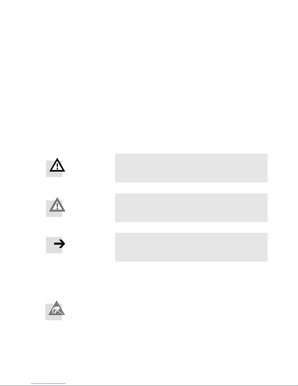
Warning
... means that failure to observe this instruction may result
in serious personal injury or damage to property.
Caution
... means that failure to observe this instruction may result
in personal injury or damage to property.
Note
... means that failure to observe this instruction may result
in damage to property.
The following pictogram marks passages in the text which
describe activities using electrostatically sensitive devices.
Festo P.BE-CDVI-EN en 1202e
Electrostatically sensitive devices: inappropriate handling
can result in damage to components.
IX
Page 12

Contents and general safety instructions
Identification of specific information
The following pictograms mark passages in the text which
contain special information.
Pictograms
Information:
Recommendations, tips and references to other sources
of information.
Accessories:
Information on necessary or useful accessories for the
Festo product.
Environment:
Information on the environmentally friendly use of Festo
products.
Text designations
•
The bullet indicates activities which may be carried out in
any order .
1. Digits indicate activities which must be carried out in the
specified sequence.
– Arrowheads indicate general lists.
X
Festo P.BE-CDVI-E N en 1202e
Page 13

Contents and general safety instructions
Abbreviations
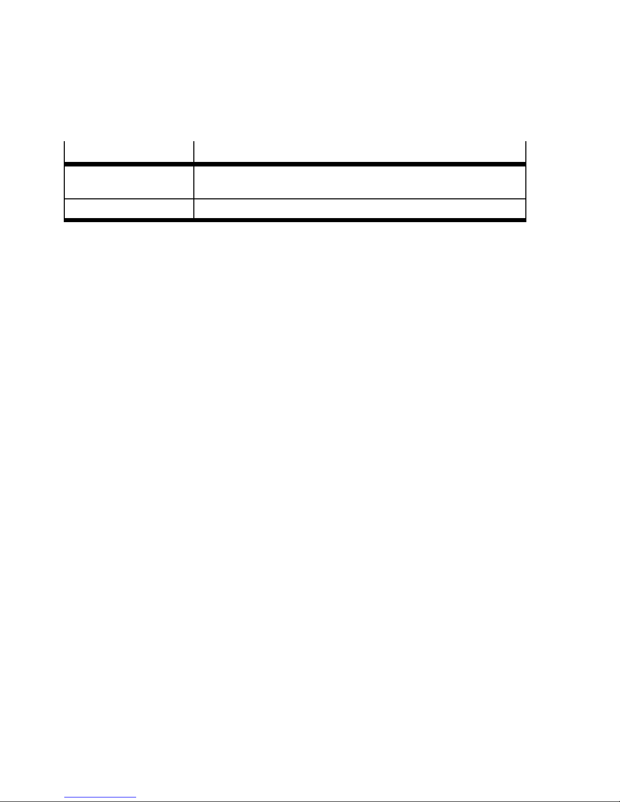
The following product-specific terms and abbreviations are
used in this manual:
T erm / abbreviation
Bi-expansion block Expansion block that supports triggering 2 solenoid coils per valve
Blanking plate Plate with hood for covering an unused valve position (vacant position)
CDVI-DN CDVI with fieldbus direct link “DeviceNet ”
CDVI-FB General for CDVI with fieldbus direct link
CDVI-MP CDVI with electrical multi-pin plug connection (MP connection)
CDVI/terminal or valve
terminal
Component Common term for manifold blocks, expansion blocks, end plates, valves
DI connection Fieldbus direct. This variant of the CDVI can be connected directly to
End plate Blanking plate at the left and right-hand ends of the CDVI with connec-
Meaning
position.
Clean Design Valve terminal (type 15)
and blanking plates
the appropriate fieldbus, e.g. DeviceNet.
tions for supplying the valves with compressed air and for removing
the exhaust air.
Ident. code/I.D. Identification code
Connection block General for manifold block and expansion block
Manifold block Connection block with 4 or 8 valve positions that always supports
MO Manual override
Mo expansion block Expansion block that suppor ts triggering 1 solenoid coil per valve
MP connection Valve terminal variant with multi-pin plug connection and cable.
Regulators Pressure regulator
Festo P.BE-CDVI-EN en 1202e
triggering 2 solenoid coils per valve position
position
All solenoid coils are connected centrally via the multi-pin cable.
XI
Page 14
Contents and general safety instructions
T erm / abbreviation Meaning
Separator plate Sealing variant with open or closed supply ducts. The variants with
closed supply ducts serve to form pressure zones.
Tubing connection Connecting the supply lines (tubing) to the CDVI.
Tab. 0/1: Index of terms and abbreviations
XII
Festo P.BE-CDVI-E N en 1202e
Page 15

Overview of components
Chapter 1
Overview of components
Festo P.BE-CDVI-EN en 1202e
1-1
Page 16

1. O verview of components
Contents
1. Overview of components 1-1........................................
1.1 The Clean Design valve terminal (CDVI) from Festo 1-4....................
1.2 Description of variants 1-5...........................................
1.3 Description of components 1-6.......................................
1.3.1 In-line valve manifolds 1-7...................................
1.3.2 End plates 1-9.............................................
1.3.3 Valves 1-10.................................................
1.3.4 Connection, display and control elements 1-12....................
1-2
Festo P.BE-CDVI-E N en 1202e
Page 17

1. O verview of components
Contents of this chapter This chapter provides an overview of the following aspects of
the CDVI:
– Variants of the valve terminal
– The components of the valve terminal
– Identification code of the pneumatic components
– Connection, display and control elements
Further information Information on the electrical components of the CDVI with
MP connection can be found in the brief description of the
Clean Design valve terminal (CDVI, type 15) with multi-pin
connection.
Information on the electrical components of the CDVI with
DI connection “DeviceNet” can be found in the Electronics
Manual CDVI-DN.
Festo P.BE-CDVI-EN en 1202e
1-3
Page 18

1. O verview of components
1.1 The Clean Design valve terminal (CDVI) from Festo
The CDVI from Festo is a valve terminal especially for the
splash range in the food and packing industry. It offers the
following advantages:
– Easy to clean (larger spaces between the valves, no sharp
edges, no narrow radii, no dirty corners)
– Increased resistance to corrosion
– Resistance to acid and alkaline cleaning agents
– Complies with relevant protection classes (see Appendix A
“Technical data”).
– Low maintenance
– Pre-assembled valves
– Wired solenoid coils
– Central air supply
– Centrally ducted exhaust air
– Inspected unit
– Extension/conversion possible at a later stage
1-4
Festo P.BE-CDVI-E N en 1202e
Page 19
1. O verview of components
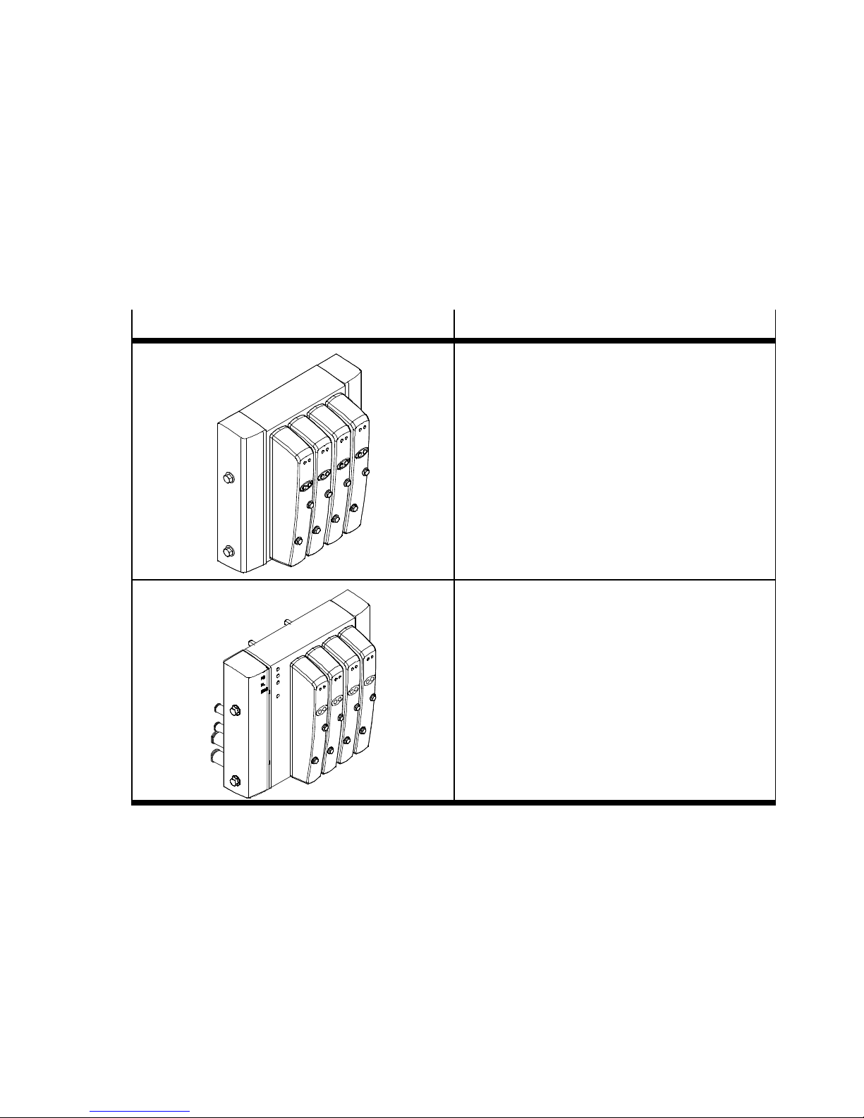
1.2 Description of variants
The CDVI is available with the following alternative electrical
connections:
CDVI variant
Remarks
CDVI with MP connection
With this CDVI, the multi-pin cable has already
been fitted onto the valve terminal at the factory.
CDVI with DI connection “DeviceNet”
Tab. 1/1: Variants of the CDVI
Festo P.BE-CDVI-EN en 1202e
1-5
Page 20
1. O verview of components
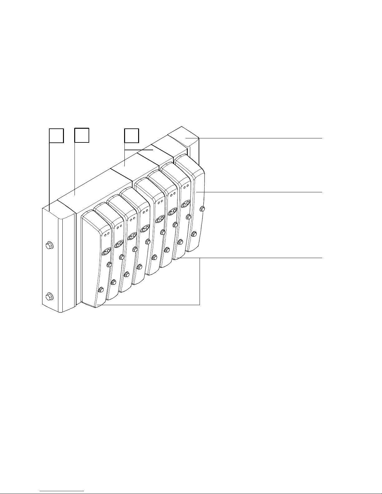
1.3 Description of components
The CDVI consists of individual components.
1
2
3
4
5
6
1
Left-hand end plate with pneumatic
connections (1), (12/14), (3/5),
(82/84) and on the CDVI-MP with
MP connection
2
Manifold block 4 or 8 valve positions
3
Optionally up to 8 expansion blocks
possible with 1 valve position each
Fig. 1/1: Overview of components of the CDVI
1-6
4
Right-hand end plate with pneumatic
connections (1), (3/5) for internal or
external pilot air supply
5
Blanking plate on vacant position
6
Valves
Festo P.BE-CDVI-E N en 1202e
Page 21

1. O verview of components
1.3.1 In-line valve manifolds
There are two types of in-line manifold blocks on the CDVI:
– The manifold block has 4 or 8 valve positions. Each CDVI
consists of at the most one manifold block, i. e. no further
manifold blocks can be used for additional valve positions.
– The expansion blocks (2-valve or 1-valve expansion block)
are available in four different versions:
– Standard version without power supply
– Version with pneumatic supply connection
– In addition, on the CDVI with fieldbus connection:
– Version with electrical power supply
– Version with pneumatic supply connection and
electrical power supply
Both versions provide 1 or 2 valve positions. A maximum of
8Mo-expansionblocksor4Bi-expansionblockscanbe
mounted to one manifold block. Mixed components are permissible.
Valves and blanking plates are fitted on the in-line valve manifolds. The working lines (2) and (4) are provided for each
valve position on the in-line valve manifolds. Each valve position supports triggering 2 solenoid valves (only applies to
manifold blocks, otherwise depends on expansion). The end
plates form the termination. The in-line valve manifolds provide the following connections:
Festo P.BE-CDVI-EN en 1202e
– Common channels for supply and exhaust air for:
– Compressed air supply to the valves
– Removal of the exhaust and pilot exhaust air at the
valves.
– Electric signals from all solenoid coils.
1-7
Page 22
1. O verview of components
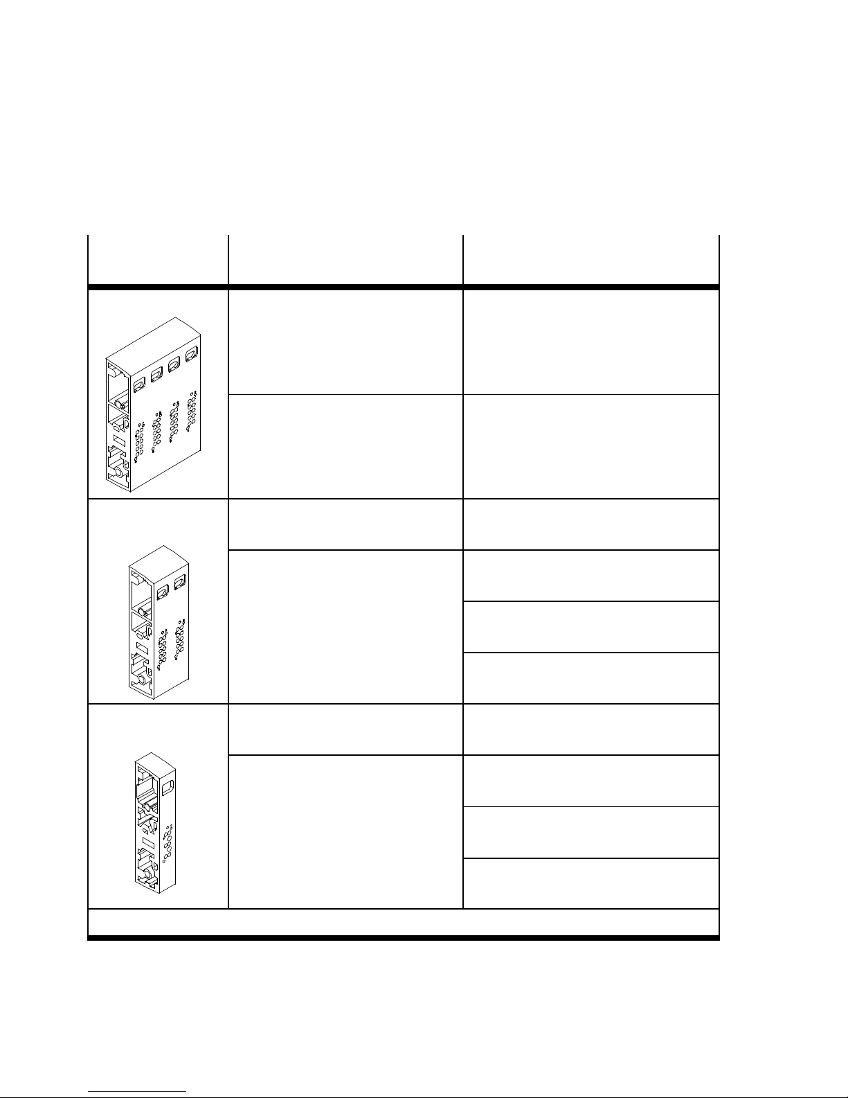
In-line valve
manifolds
Manifold block
2-valve expansion
block
Description Identification features
Manifold block with 4 valve positions
Manifold block with 8 valve positions
Standard expansion block with
2 valve positions
Expansion block with additional
supply with 2 valve positions and
connections 1, 3 and 5.
This expansion block can be used
e.g. for creating further pressure
zones.
–
4 valve positions, working lines
–
8 valve positions, working lines
–
2 valve positions, working lines,
no supply ports
–
2 valve positions, working lines,
pneum. supply ports
–
2 valve positions, working lines,
power supply
–
2 valve positions, working lines,
pneum. ports and power supply
1)
1)
1-valvle expansion
block
1)
only on the CDVI with fieldbus connection
Standard expansion block with
1 valve position
Expansion block with additional
supply with 1 valve position and
ports 1, 3 and 5.
This expansion block can be used
e.g. for creating further pressure
zones.
T ab. 1/2: Overview of in-line valve manifolds for the CDVI
1-8
–
1 valve position, working lines,
no supply ports
–
1 valve position, working lines,
pneum. supply ports
–
1 valve position, working lines,
power supply
–
1 valve position, working lines,
pneum. ports and power supply
1)
Festo P.BE-CDVI-E N en 1202e
1)
Page 23
1. O verview of components
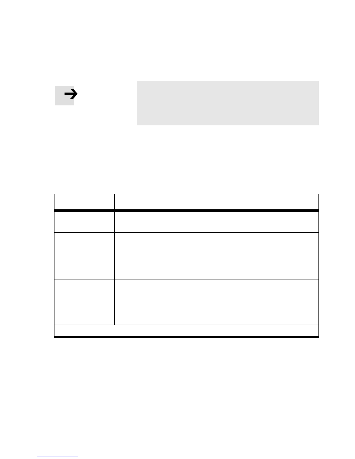
Note
With more than 2 pressure zones:
Ensure that there is a corresponding pneumatic supply
port for each pressure zone.
Separator plates with sealing function are located between the
manifold block and the expansion block. There are designs with
or without channel separation (see following table).
The in-line valve manifolds of the CDVI can be fitted with the
following components:
Component
Valves and blanking
plate
Separator plates
End plates, right
End plates, left
*)
Pressure zones are only possible for CDVIs with at least one expansion block.
Design/type
see Tab. 1/4
*)
–
–
–
–
–
–
–
–
All supply ducts open: CDVI5.0-EB-DZ
Separating the compressed air channel (1): CDVI5.0-EB-DZP
Separating the exhaust duct (3/5): CDVI5.0-EB-DZR
Separating the compressed air channel and the exhaust duct: CDVI5.0-EB-
DZPR
For operating the CDVI with internal pilot air supply: CDVI5.0-EPR
For operating the CDVI with external pilot air supply: CDVI5.0-EPR-S
With CDVI-MP: CDVI5.0-EPL-MP-... (with electric multi-pin and cable)
With CDVI-FB: CDVI5.0-EPL-FB
T ab. 1/3: Pneumatic components of the CDVI
1.3.2 End plates
Festo P.BE-CDVI-EN en 1202e
The CDVI possesses as mechanical termination of the terminal
both a left and a right-hand end plate. These end plates fulfil the
following functions:
1-9
Page 24

1. O verview of components
– Ensure the protection class (see Appendix A “Technical
data”).
– Via the left-hand end plate, the CDVI is supplied with com-
pressed air (connections (1), (12/14)), the exhaust air is
removed (connections (3/5), (82/84)) and with the CDVIMP the terminal is supplied with voltage.
– Via the right-hand end plate the CDVI can also be sup-
plied with compressed air (connection (1)) and the exhaust air can be removed (connection (3/5)). The righthand end plate variant determines whether the CDVI is to
be operated with internal or external pilot air supply:
1.3.3 Valves
– Right-hand end plate type CDVI5.0-EPR
for supplying the valves with internal pilot air,
branched from the overall supply (compressed air
channel (1)).
– Right-hand end plate type CDVI5.0-EPR-S
for supplying the valves with external pilot air, pressure regulated separately (3 ... 8 bar). The external
pilot air is supplied via connection (12/14) on the lefthand end plate.
Note
The valve positions are intended for Festo valves and may
be fitted only with the valves approved of by Festo.
The valve positions must not be used for any other purpose.
1-10
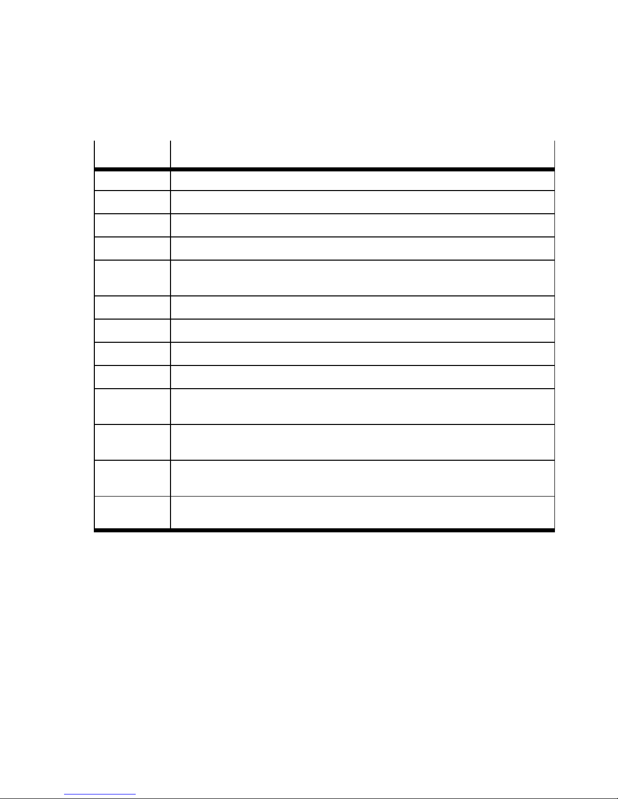
The components on the valve positions are marked with
identification codes. With these codes you can ascertain the
equipment fitted on your CDVI. The codes are printed on the
covers of the valves or on the blanking plate. An overview of
the valves can be found in Appendix A.
Festo P.BE-CDVI-E N en 1202e
Page 25
1. O verview of components
Ident. code Component
A Blanking plate for vacant position
B 5/3-way valve, open in mid-position
E 5/3-way valve, mid-position exhausted
G 5/3-way valve, mid-position closed
H Two 3/2-way valves, monostable, control side 14 closed in normal position,
control side 12 open in normal position
J 5/2-way valve, bistable
K Two 3/2-way valves, monostable, normal position closed
M 5/2-way valve, monostable
N Two 3/2-way valves, monostable, open in normal position
R 2/2-way valves, monostable, control side 14 closed in normal position, external
compressed air supply
S 2/2-way valve, monostable, open in normal position, external compressed air
supply
W One 3/2-way valve, monostable, open in normal position, external compressed
air supply
X One 3/2-way valve, monostable, closed in normal position, external compressed
air supply
Tab. 1/4: Identification code of the valve position components
Festo P.BE-CDVI-EN en 1202e
1-11
Page 26
1. O verview of components
1.3.4 Connection, display and control e lements
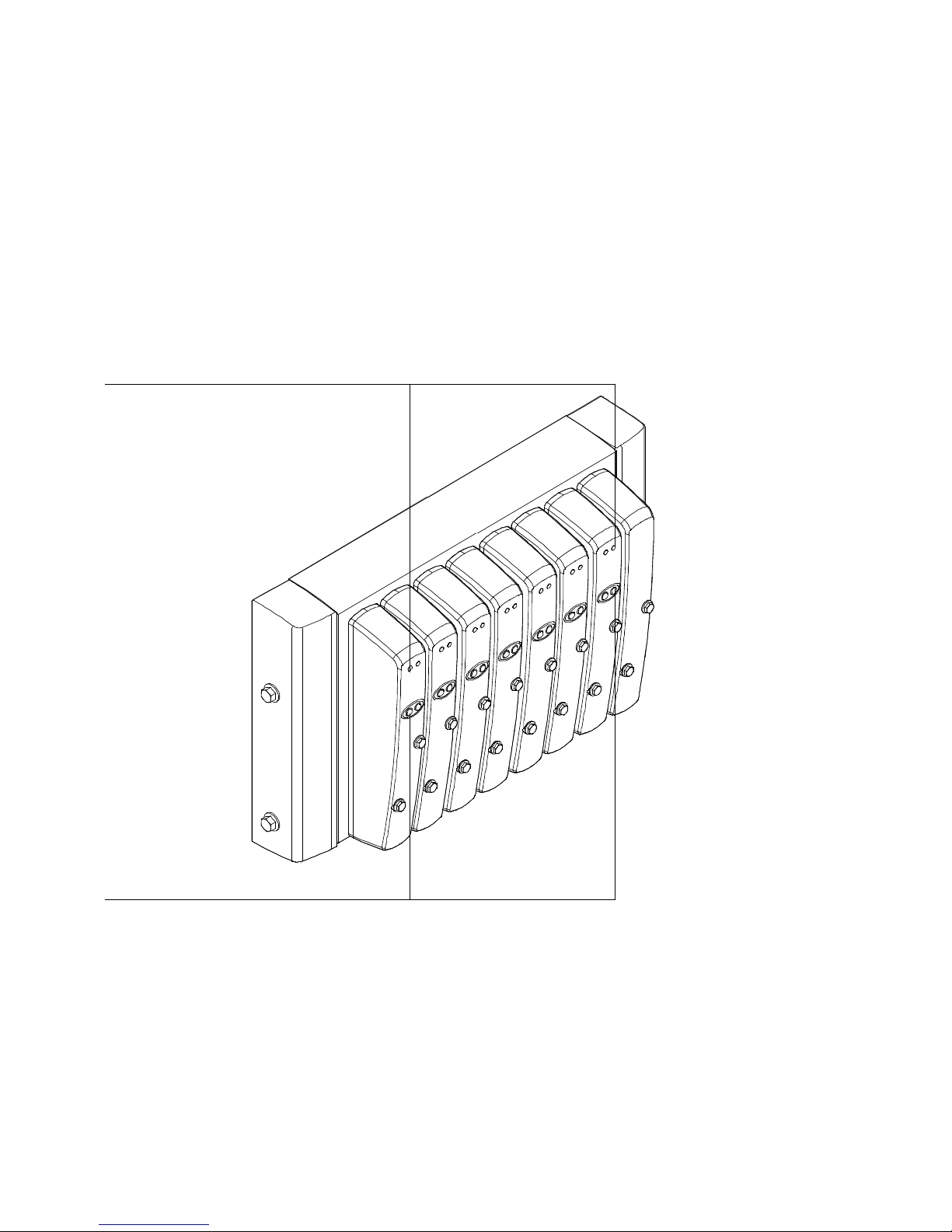
The following display and control elements can be found on
the valve side of the CDVI with MP connection:
1
2
1
Yello w LEDs, status display of the
solenoid coils
Fig. 1/2: Display and control elements of the CDVI with MP connection
1-12
2
Manual overrides (per solenoid coil)
Festo P.BE-CDVI-E N en 1202e
Page 27
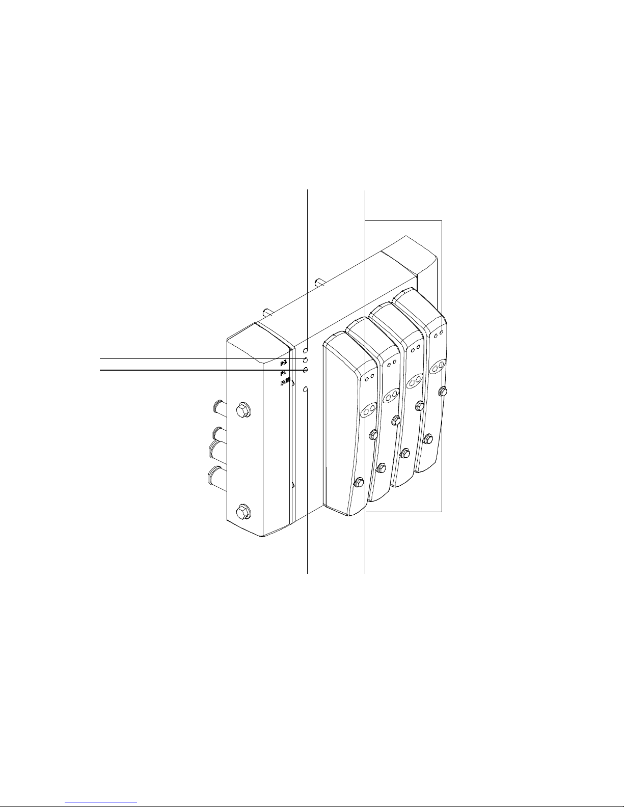
1. O verview of components
The following display and control elements can be found on
the valve side of the CDVI with DI connection “DeviceNet:”
12
6
5
1
Green LED PS “Power System,”
electronics operating voltage
2
Yello w LEDs, status display of the
solenoid coils
4
3
4
Green/red LED CP “Compact
Performance,” CP extension modules
5
Green/red LED MNS “Module/
Network Status”
3
Manual overrides (per solenoid coil)
Fig. 1/3: Display and control elements of the CDVI with DI connection “DeviceNet”
Festo P.BE-CDVI-EN en 1202e
6
Green LED PL “Power Load,” valve load
voltage
1-13
Page 28
1. O verview of components
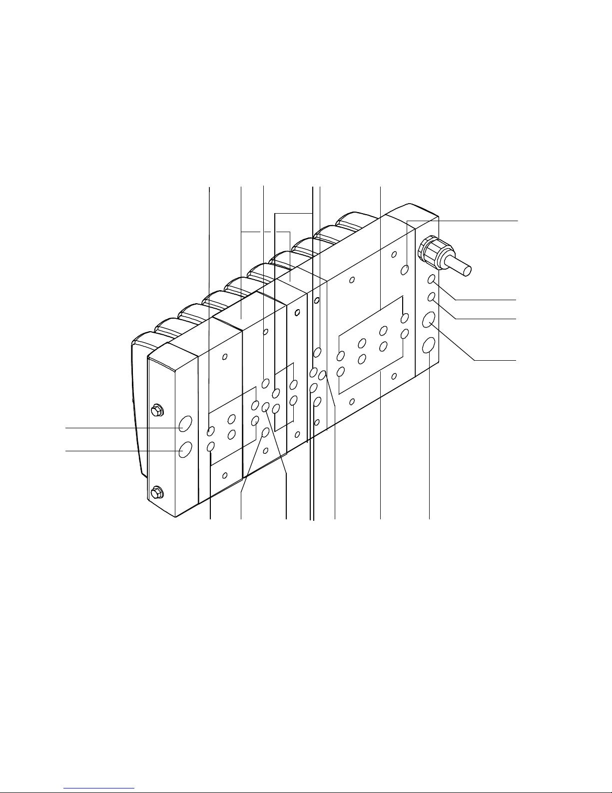
The following pneumatic connecting elements can be found
on the connection side of the CDVI:
2
1
5
3
45
4
5
6
7
8
1
1
Supply port (1)
2
Exhaust port (3/5)
3
Expansion block with additional supply
ports
4
Exhaust port (5) on the expansion
block
5
Working line (4) per valve
6
Pressure compensation connection (L)
Fig. 1/4: Connection elements of the pneumatic components
1-14
9
aJaA
7
8
9
aJ
aA
9 aA aJ
Exhaust port (82/84)
Pilot air supply port (12/14)
Working line (2) per valve
Supply port (1) on expansion block
Exhaust port (3) on expansion block
9
2
Festo P.BE-CDVI-E N en 1202e
Page 29
1. Overview of components
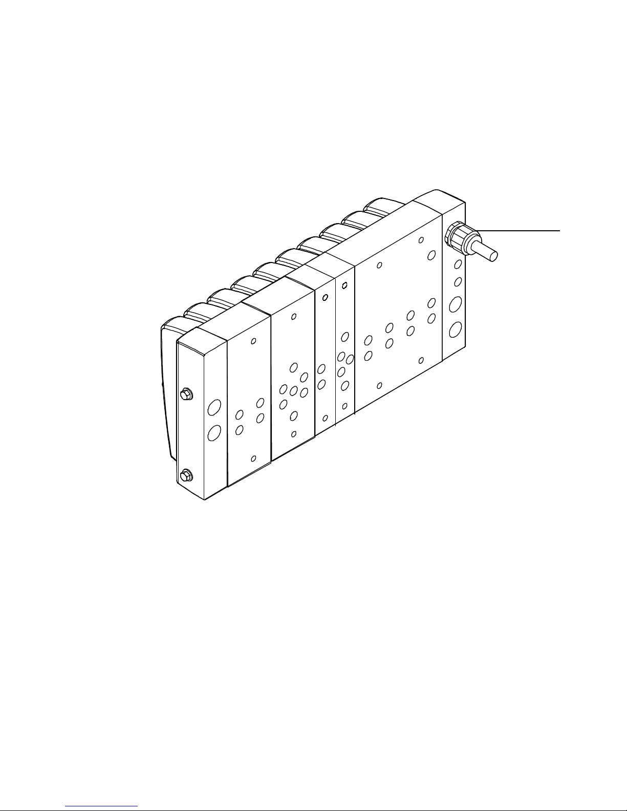
The following electrical connection can be found on the
connection side of the CDVI with MP connection:
1
1
Electric multi-pin plug connection
Fig. 1/5: Electrical connection element of the CDVI with MP connection
Festo P.BE-CDVI-EN en 1202e
1-15
Page 30
1. Overview of components
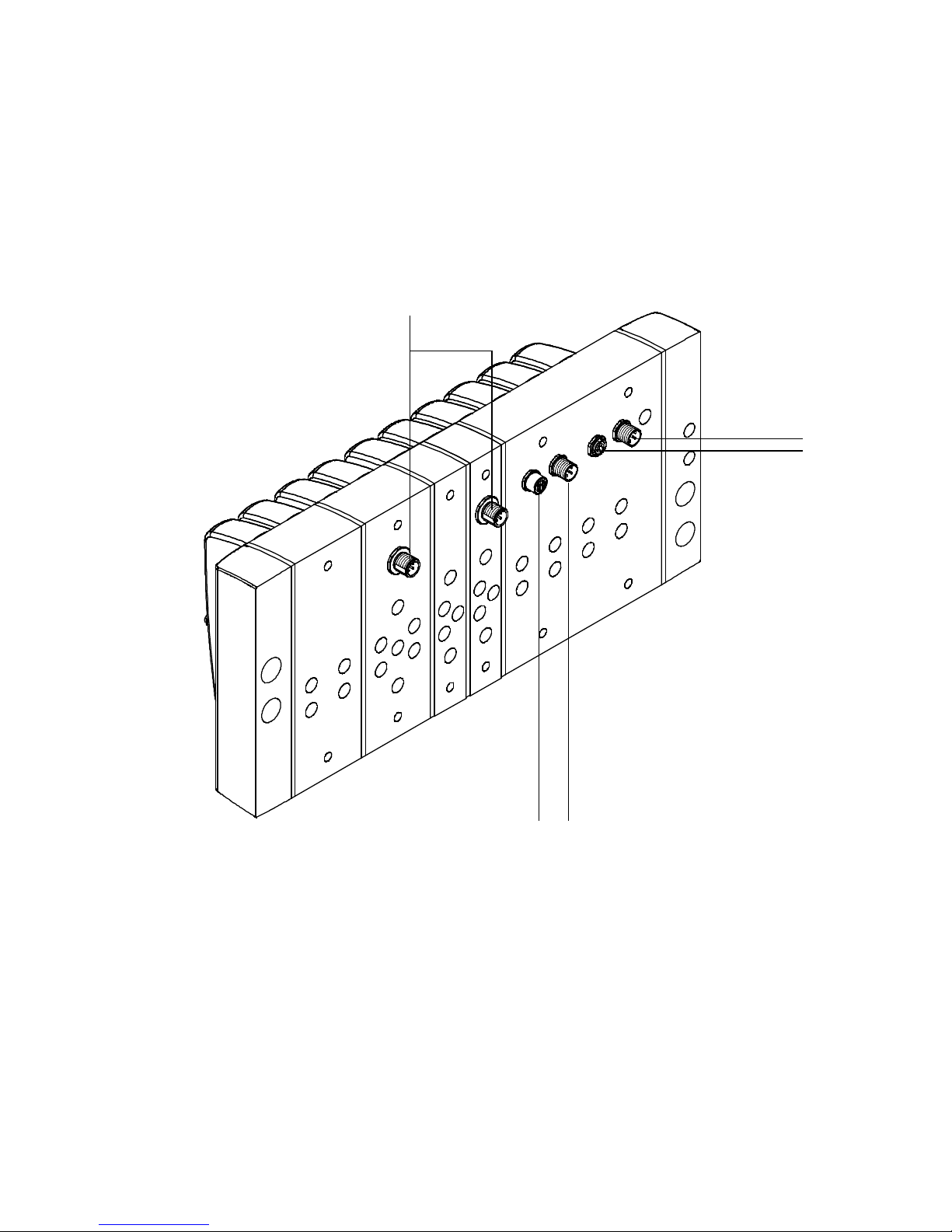
The following electrical connection elements can be found
on the connection side of the CDVI with DI connection
“DeviceNet:”
5
4
3
1
Fieldbus output (socket, M12)
2
Fieldbus input (plug, M12)
Fig. 1/6: Electrical connections of the CDVI with DI connection “DeviceNet”
1-16
12
3
CP expansion (M9)
4
Power supply (plug, M12)
5
Additional electrical supply on
expansion block
Festo P.BE-CDVI-E N en 1202e
Page 31

Assembly
Chapter 2
Assembly
Festo P.BE-CDVI-EN en 1202e
2-1
Page 32

2. Assembly
Contents
2. Assembly 2-1.....................................................
2.1 Mounting the valve terminal 2-4......................................
2.1.1 Wall mounting 2-5..........................................
2-2
Festo P.BE-CDVI-E N en 1202e
Page 33

2. Assembly
Contents of this chapter This chapter describes how to assemble the CDVI on a
mounting surface.
Further information The CDVI is pre-mounted when supplied by the plant. If you
wish to supplement or replace pneumatic components, note
the instructions in chapter 5 “Cleaning, maintenance and
conversion.”
Festo P.BE-CDVI-EN en 1202e
2-3
Page 34

2. Assembly
2.1 Mounting the valve terminal
Warning
Uncontrolled movements of the connected actuators and
uncontrolled movements of loose tubing can cause injury
to persons and/or damage to property.
•
Make sure that the higher-order controller has not sent
control signals to the solenoid coils.
•
Before carrying out conversion work on the CDVI, switch
off the following:
– The compressed air supply
– The power supply
Note
Handle all the components of the CDVI with great care.
Note especially the following:
– Avoid an offset between the components, otherwise
the protection class requirements may no longer be
fulfilled (see Appendix A, “Technical data”).
– Components must be screwed without offset and
mechanical stress. Screws must be fitted accurately
(otherwise threads may be damaged)
– Observe the specified tightening torques.
– Make sure that the connecting surfaces are clean
(avoid leakage and contact faults).
– Avoid operating the CDVI in the resonant range.
2-4
Festo P.BE-CDVI-E N en 1202e
Page 35
2. Assembly
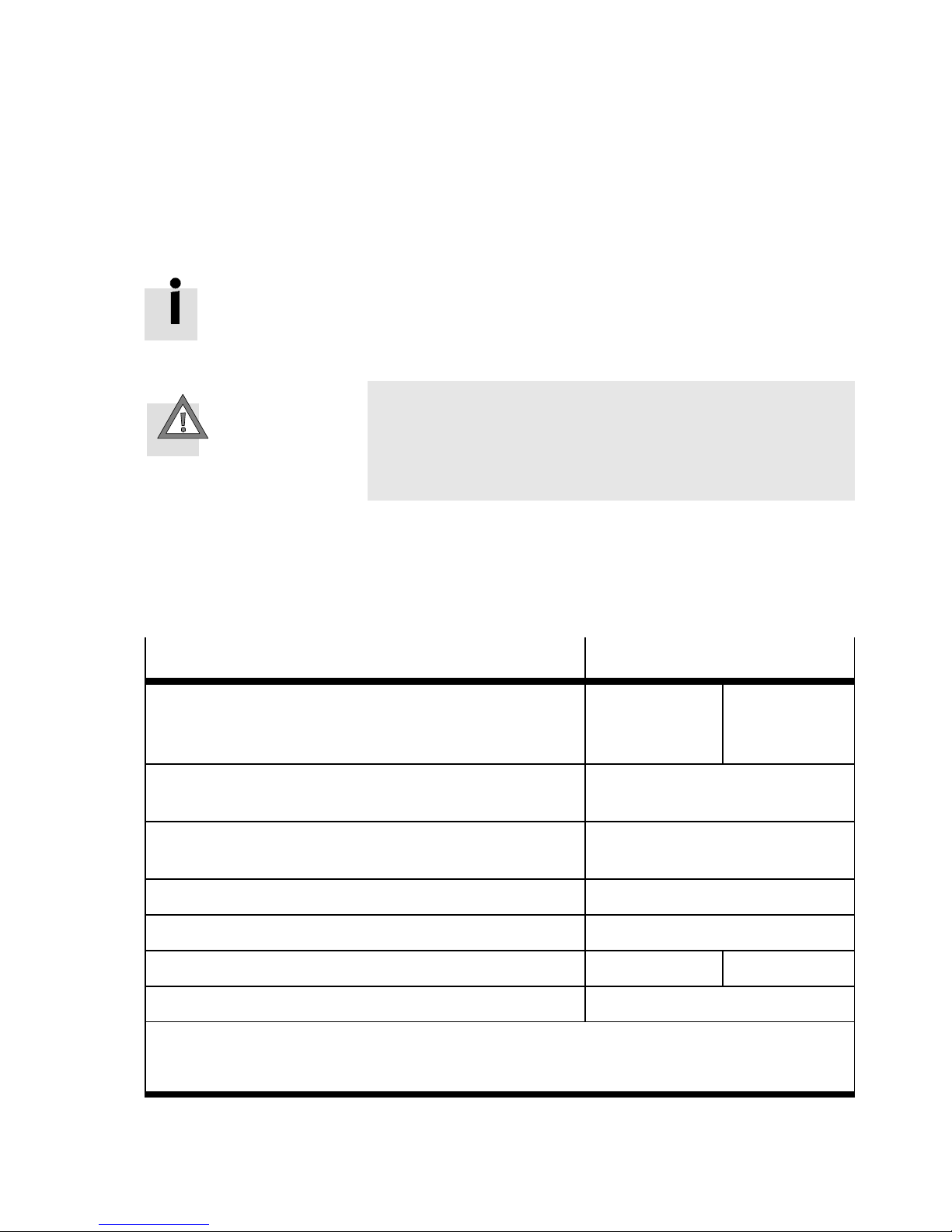
2.1.1 Wall mounting
It may be sensible to connect the tubing prior to mounting
the CDVI, depending on the space available for mounting.
The tubing of the terminal is described in chapter 3.
Caution
The CDVI can bend and therefore become damaged and
may leak if it is mounted on an uneven and pliable surface.
•
Mount the CDVI only on an even rigid surface.
Procedure:
1. Ascertain the weight of your terminal (weigh or calculate).
Guidelines:
Components of the CDVI
Basic weight:
–
CDVI with 4 valve positions
–
CDVI with 8 valve positions
Expansion block with 1 valve position
–
With/without additional supply
Expansion block with 2 valve positions:
–
With/without additional supply
Valve approx. 210 g/item
Blanki n g plate approx. 85 g/item
Multi-pin connecting cable per metre approx. 168 g/m ---
1)
2)
2)
Weight
CDVI-MP
approx. 1050 g
approx. 2090 g
approx. 255 g
approx. 510 g
CDVI-FB
approx. 1320 g
approx. 2360 g
Spacer bolt approx. 80 g/item
1)
Manifold block, without: separator plates, left-hand and right-hand end plates, pneum.
threaded connectors, cable, valv e
2)
Expansion block without: separator plate and pneum. threaded connectors, valves
T ab. 2/1: Weight specifications for the CDVI
Festo P.BE-CDVI-EN en 1202e
2-5
Page 36
2. Assembly
2. Make sure that your mounting surface can support this
weight and that it is sufficiently earthed.
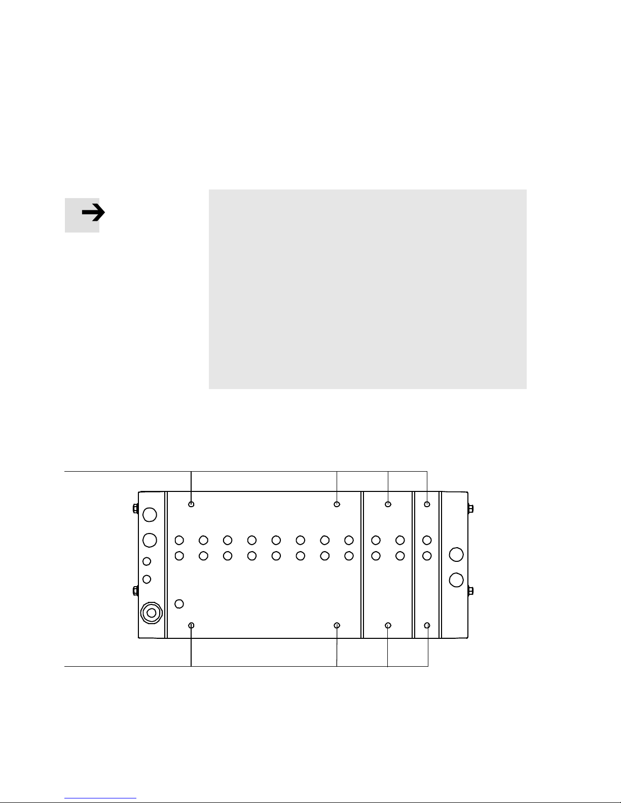
Note
Attaching the CDVI manifold block:
– The 8-valve manifold block must always be fastened to
all 4 M6 drill holes.
Attaching the CDVI with expansion blocks:
– 1 valve position may protrude unfastened.
– If the expansion provides more than one valve position,
fasten the last expansion block. However, please note
that a maximum of 4 valve positions may lie unsupported between the manifold block and last expansion
block, i.e. you need to fit an intermediate retainer after
4 valve positions at the latest.
1
1
1
Mounting holes
3. Drill corresponding mounting holes
mounting surface.
∅
6mmintothe
Fig. 2/1: Position of the mounting holes
2-6
Festo P.BE-CDVI-E N en 1202e
Page 37
2. Assembly
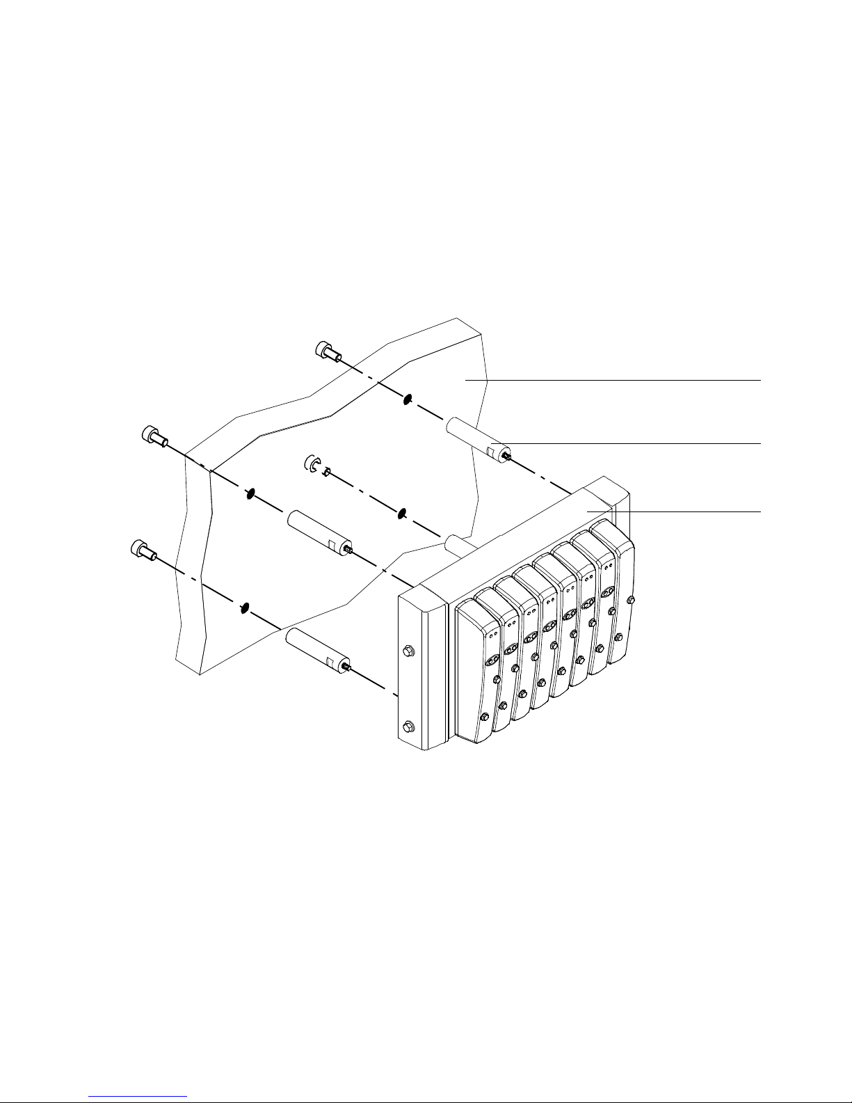
4. Fasten the terminal conductively with the earthed mounting
surface (see Fig. 2/2). If necessary use washers. The terminal can be mounte d in any desired posit i o n , but the CDVI
should be mounted so that dirt will be washed out during
cleaning and the cleaning agent can drip off.
1
1
Earthed mounting surface
2
Spacer bolt, tightening torque 10 Nm
(±2 Nm)
3
Manifold block with threaded holes
forspacerbolts
2
3
Fig. 2/2: Example of vertical attachment
Festo P.BE-CDVI-EN en 1202e
2-7
Page 38

2. Assembly
Note
If you do not use the spacer bolts from Festo, note the
following:
– Make sure that there is a gap of at least 90 mm around
the CDVI, e.g. by means of mounting profiles or a section
cut out of the mounting surface, so that the tubing is not
bent.
– Make sure that there is a good conductive connec-
tion between the mounting profile and the earthed
mounting surface.
– Use the M6 mounting holes in the manifold block if you
wish to mount the CDVI on a wall (thread depth 9.5 mm).
2-8
Festo P.BE-CDVI-E N en 1202e
Page 39

Installation
Chapter 3
Installation
Festo P.BE-CDVI-EN en 1202e
3-1
Page 40

3. Installation
Contents
3. Installation 3-1...................................................
3.1 Compressed air preparation 3-4......................................
3.1.1 Operation with unlubricated compressed air 3-4.................
3.1.2 Operation with lubricated compressed air 3-5....................
3.2 General instructions on installation 3-7................................
3.3 Laying the tubing 3-8...............................................
3.4 Notes on installing the CDVI 3-10......................................
3.4.1 Pilot control of the solenoid coils (pilot air supply) 3-10.............
3.4.2 CDVI with pressure zone separation 3-11........................
3.4.3 Operating the CDVI with vacuum/low pressure 3-16...............
3.5 Connecting the CDVI 3-18.............................................
3.5.1 Connecting the pneumatic lines 3-18............................
3.5.2 Connecting the electric cables 3-22.............................
3.6 Address assignment of the valves 3-23..................................
3-2
Festo P.BE-CDVI-E N en 1202e
Page 41

3. Installation
Contents of this chapter This chapter deals with the tubing and cabling of the CDVI.
These include in particular the following:
– General instructions on preparing the compressed air and
on connecting the tubing
– Instructions on operating the pilot control with internal or
external pilot air supply
– Instructions on operating the valve terminal with pres-
sure-zone separation
– Fitting the QS threaded connectors
– Connecting the power supply
–EarthingtheCDVI
– Address assignment of the valves
Further information Instructions on connecting the electric components of the
CDVI with MP connection can be found in the brief description
“CDVI with multi-pin plug connection.”
Instructions on connecting the electric components and on
addressing the CDVI with DI connection “DeviceNet” can be
found in the electronics manual P.BE-CDVI-DN-..
Festo P.BE-CDVI-EN en 1202e
3-3
Page 42

3. Installation
3.1 Compressed air preparation
Note
Unfiltered or incorrectly lubricated compressed air will
reduce the service life of the valve terminal.
3.1.1 Operation with unlubricated compressed air
Note
T oo much residual oil content in the compressed air will
reduce the service life of the valve terminal.
– If bio oils are used (oils based on synthetic esters or nat-
ive esters, e.g. rapeseed oil methylic ester), the residual
oil content must not exceed max. 0.1 mg/m
3
(see ISO
8573-1 class 2).
– If mineral oils are used (e.g. HLP oils to DIN 51524 Part 1
to 3) or corresponding oils based on polyalphaolefin
(PAO ), the residual oil content must not exceed 5 mg/m
(see ISO 8573-1 class 4).
This avoids operative malfunction of the valves.
Excessive residual oil is not permissible irrespective of the
compressor oil, as otherwise the basic lubrication will be
washed out with time.
3
3-4
Festo P.BE-CDVI-E N en 1202e
Page 43
3. Installation
3.1.2 Operation with lubricated compressed air
Operate your system with unlubricated compressed air if
possible. This will prevent pollution of the environment.
Festo pneumatic valves and actuators have been designed
so that, if used as intended, they will not require additional
lubrication and will still achieve a long service life.
Caution
Operation with lubricated compressed air will cause the
life-time lubrication, which is necessary for unlubricated
operation, to be “washed out”.
Note the following instructions if lubricated compressed air
must be used.
The compressed air prepared with the compressor must
correspond in quality to unlubricated compressed air. If possible, do not operate the complete system with lubricated compressed air . If possible, always install the lubricators directly in
front of the consuming actuator.
Caution
Incorrect additional oil and too much residual oil content in
the compressed air will reduce the service life of the valve
terminal.
– Use Festo special oil OFSW-32 or the other oils listed in
the Festo catalogue (conforming to DIN 51524-HLP32,
basic viscosity 32 CST at 40°C).
– The additional lubrication must not exceed 25 mg/m
3
(ISO 8573-1 class 5).
– Check that the lubricator setting is correct (see sub-
sequent section)
Festo P.BE-CDVI-EN en 1202e
This avoids operative malfunction of the valves.
3-5
Page 44

3. Installation
Setting the lubricator: with the machine running (typical operating status) 0.2 to
max. 1 drop/min. or 0.5 to 5 drops/1000 l air.
Checking the setting: the procedure described below can be used for checking the
setting of the lubricator.
Procedure:
•
Check the service units for condensate and lubricator
setting twice per week.
1. Ascertain the actuator which is furthest from the lubricator.
2. Ascertain the valve terminal which controls this cylinder.
3. Remove the silencer, if fitted, from port (3/5).
4. Hold a piece of white cardboard 10 cm in front of the exhaust port.
5. Let the system run for a short period.
– There must be only a slight yellow colouring on the card-
board. If oil drips out, this is an indication that too much
oil has been used.
Another indicator of over-lubrication is the coloration or the
condition of the exhaust air silencer. A distinctly yellow colouring of the filter element or drops of oil on the silencer indicate that the lubricator setting is too high.
3-6
Festo P.BE-CDVI-E N en 1202e
Page 45
3. Installation
3.2 General instructions on installation
Warning
Sudden unexpected movements of the connected actuators and uncontrolled movements of loose tubing lines can
cause injury to human beings or damage to property.
Before carrying out mounting, installation and maintenance work, switch off the following:
– Compressed air supply
– Operating and load voltage supplies.
Pay attention to the following:
The components of the valve terminal contain electrostatically
sensitive elements. The components will be damaged if you
touch the contact surfaces of the plug connectors or if you do
not observe the handling specifications electrostatically
sensitive components.
Festo P.BE-CDVI-EN en 1202e
3-7
Page 46
3. Installation
3.3 Laying the tubing
If elbow connectors or multiple distributors are used,
the airflow will be reduced slightly .
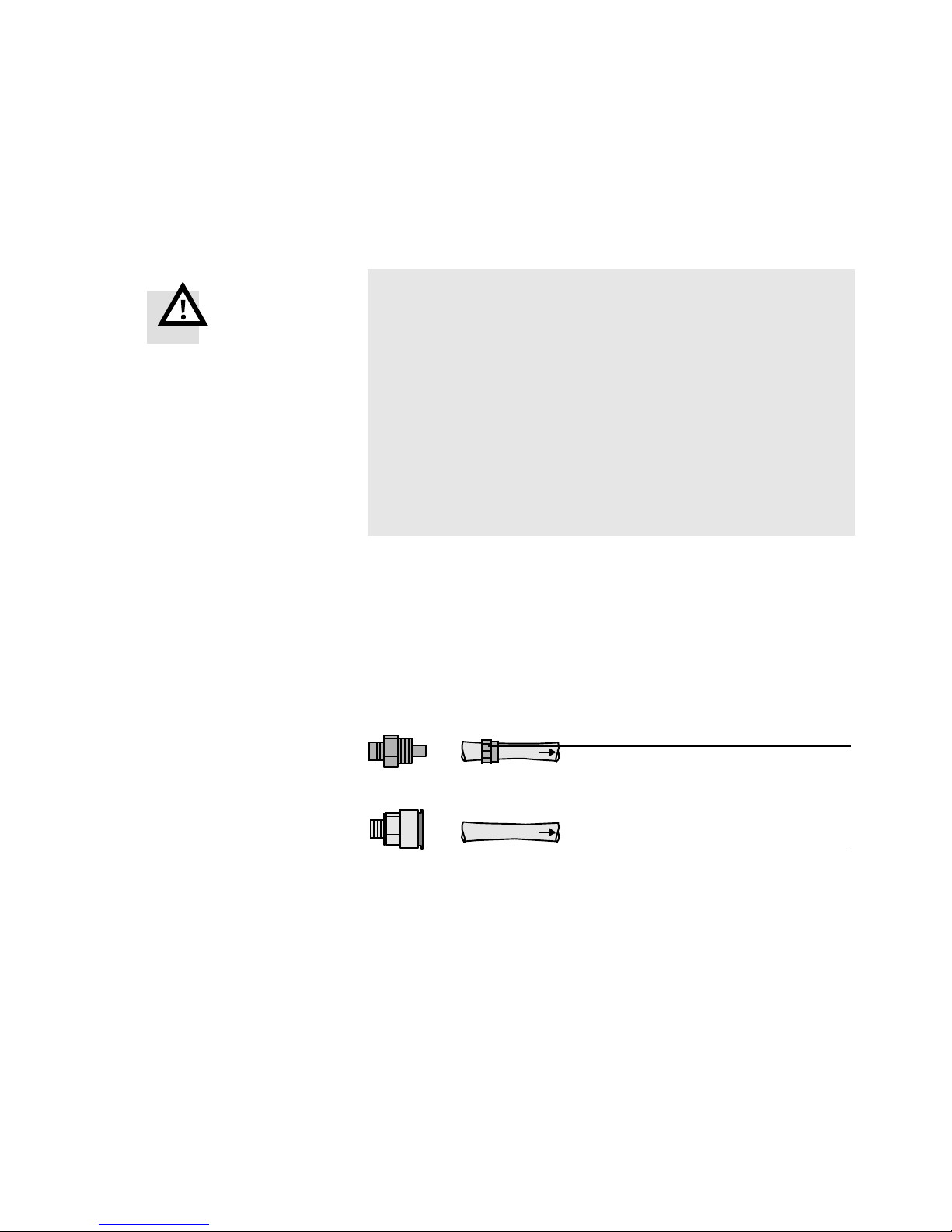
Connecting Proceed as follows:
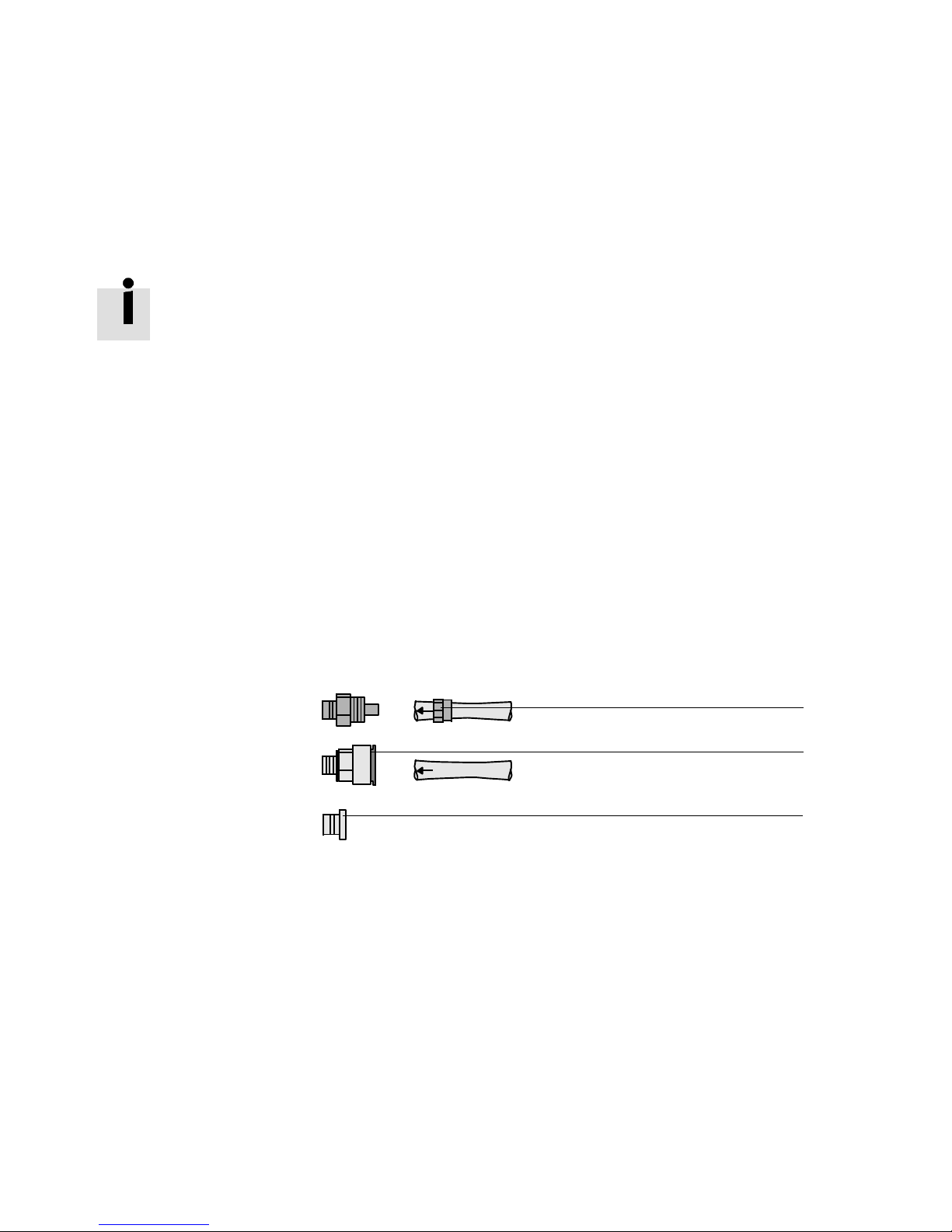
1. Push the tubing as far as possible into or over the tube
coupling of the threaded connector.
2. Tighten the clamping screw 1 or, if applicable, pull the
locking ring 2 over the tube coupling.
3. Seal connections that are not required with blanking
plugs 3.
4. For better system clarity, bundle together the installed
tubes with:
– tubing straps or
– multi-tube holder
Fig. 3/1: Fitting the tubing
1
2
3
3-8
Festo P.BE-CDVI-E N en 1202e
Page 47
3. Installation
Disconnecting Proceed as follows:
Warning
Pneumatic tubing that is under pressure can execute uncontrolled movements when being dismantled, causing
injury to persons. Carry out the following steps before disconnecting the pneumatic tubing on the CDVI valve terminal:
•
Switch off the compressed air supply.
•
Make sure that all pneumatic tubing is pressureless.
•
Exhaust all actuators controlled by valves which are
closed in normal or mid-positions.
1. Mark all pneumatic tubing.
2. Loosen the clamping screw 1 of the fitting or, if applicable, press down the locking ring of the fitting 2 e.g.
with a Festo QSO releasing tool.
3. Remove the tubing from the threaded connector.
Fig. 3/2: Disconnecting the tubing
1
2
Festo P.BE-CDVI-EN en 1202e
3-9
Page 48

3. Installation
3.4 Notes on installing the CDVI
3.4.1 Pilot control of the solenoid coils (pilot air supply)
Note
– Operate the CDVI whenever possible with unlubricated
pilot air (port (12/14)). Otherwise observe the instructions in the section “Compressed air preparation”.
– In the case of CDVI with internally branched pilot air, the
above-mentioned instruction applies also to the supply
air (port (1)).
The pilot air is supplied centrally to all valves of the CDVI.
– Therefore, operate the valve terminal either with intern-
ally branched or externally supplied pilot air .
This will ensure reliable operation of the valve terminal.
Internal pilot air supply
If the operating pressure of the CDVI is between 3 ... 8 bar,
you can operate the pilot control of the solenoid coils with an
internally branched pilot air supply.
Note
•
Internal pilot air supply is branched centrally from sup-
ply port (1) in the right end plate for all solenoid coils.
This also applies when the CDVI is operated with several
pressure zones (see Fig. 3/3 and Fig. 3/4).
3-10
Festo P.BE-CDVI-E N en 1202e
Page 49

3. Installation
If the CDVI is intended for internal pilot air supply, port
(12/14) on the left-hand end plate must be sealed with
a blanking plug.
External pilot air supply
If the operating pressure of the CDVI lies below 3 bar
or above 6 bar, pilot control of the solenoid coils must
be operated with an external pilot air supply.
Note
•
Use regulated external pilot air (3...8bar). Then reliable,
trouble-free operation of the CDVI is possible, e.g. even
with fluctuating operating pressure.
•
The external pilot air supply is supplied centrally for
all solenoid coils via the pilot port (12/14) on the left
end plate. This also applies when the CDVI is operated
with different pressure zones (see Fig. 3/3 and Fig. 3/4).
•
Set the pilot pressure of the external pilot air supply to
correspond to the operating pressure with which these
valves are operated (see Appendix A, Fig. A/1).
3.4.2 CDVI with pressure zone separation
The CDVI can be equipped with 2 to 9 pressure zones. There is
not intended to be a pressure zone separation within the manifold block. The CDVI must be fitted with at least one expansion
block in order that two pressure zones can be created.
Festo P.BE-CDVI-EN en 1202e
3-11
Page 50
3. Installation
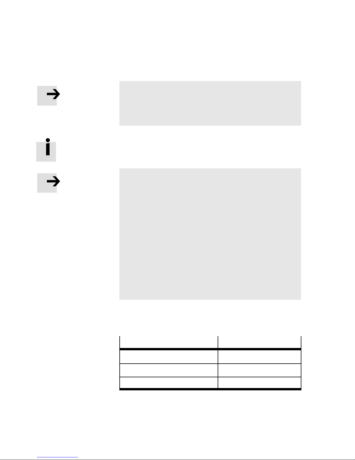
Note
With more than 2 pressure zones:
Ensure that there is a corresponding pneumatic supply
port for each pressure zone.
Conversion of the CDVI to 2 to 9 pressure zones is described
in chapter 5 “Cleaning, maintenance and conversion.”
Note
All the valves of the CDVI are supplied with pilot air from a
central source. The pilot air is either branched internally
from channel (1) or supplied externally via port (12/14).
This also applies if the CDVI has several pressure zones.
With internal pilot air supply and pressure zone separation
of channel (1), observe the following:
– The internal pilot air supply is branched in the right end
plate from channel (1). The operating pressure in the
right zone must therefore lie between 3...8 bar. In the left
and centre pressure zones the operating pressure may
lie between -0.9...10 bar and 3...10 bar, depending on
the valves that are used (see Appendix A “Technical
data”).
Separator plates For the CDVI the following separator plates are available for
creating pressure zones:
Function
Channel (1) blocked CDVI5.0-EB-DZP
Channel (3/5) blocked CDVI5.0-EB-DZR
Channels (1) and (3/5) blocked CDVI5.0-EB-DZPR
Separator plate type
3-12
Tab. 3/1: Separator plates with channel separation
Festo P.BE-CDVI-E N en 1202e
Page 51
3. Installation
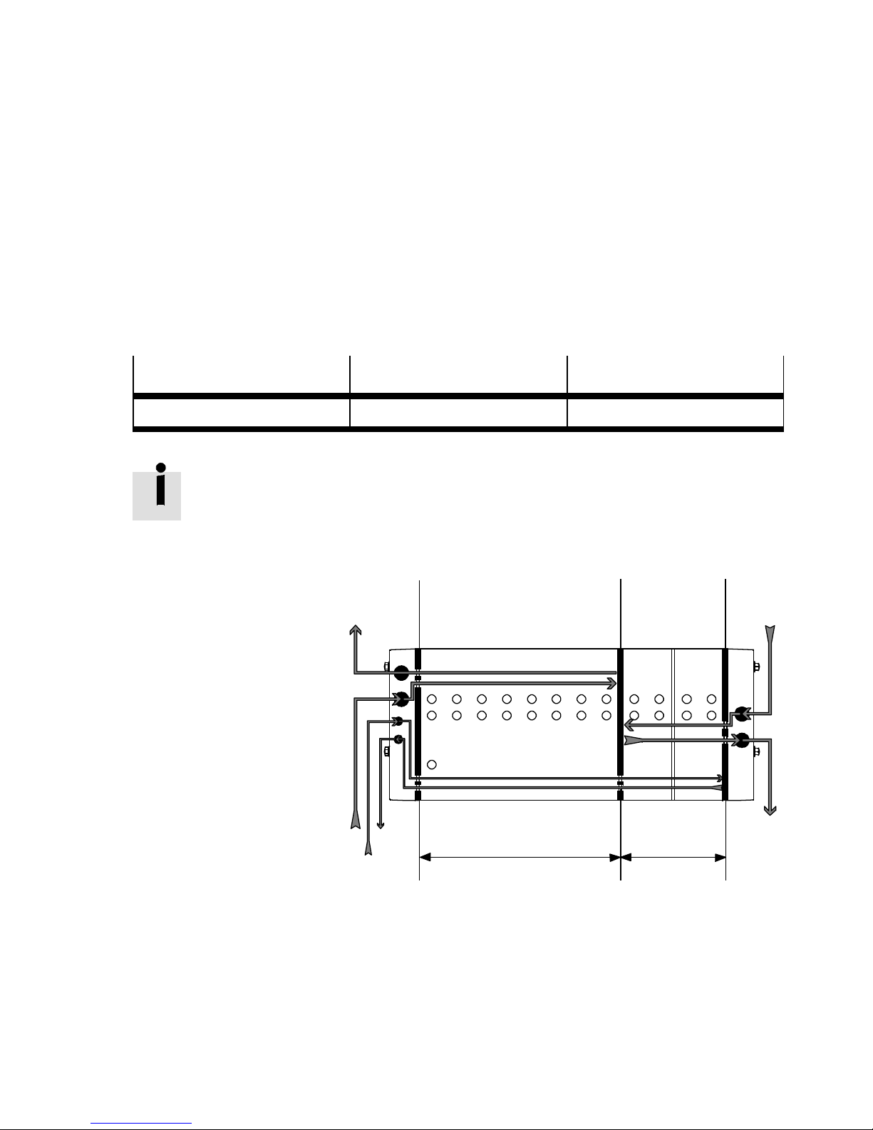
CDVI with 2 pressure zones
Prerequisite for creating 2 pressure zones:
– Depending on the electrical connection variant, the CDVI
must be fitted with at least one of the following standard
expansion blocks:
Expansion block
Standard expansion block Type CDVI5.0-EB Type CDVI5.0-EB-FB
CDVI-MP CDVI-FB
The position of the separator plate for pressure zone
separation is between the manifold block and the
expansion block.
1
Separator plate
without channel
separation
2
Separator plate
3/5
121
with channel
separation
1
Fig. 3/3: Example: CDVI with two pressure zones (channel (1) and (3/5) blocked) and
Festo P.BE-CDVI-EN en 1202e
82/84
1
12/14
pilot control with external pilot air supply
3/5
Pressure zone 2Pressure zone 1
3-13
Page 52

3. Installation
Note the following if the following separator plates are used:
Separator plates
CDVI5.0-EB-DZP EP-Land EP-R optional
CDVI5.0-EB-DZR EP-L or EP-R
CDVI5.0-EB-DZPR
or separator plate pair
CDVI5.0-EB-DZP / ...-D ZR
EP-L = End plate left
EP-R = End plate right
EB-ZV = Expansion block with additional supply
Unused ports must be sealed.
Ventilation via Exhaust via
+EB-ZV
optional
Other possibilities:
EP-Land EP-R
EP-Land EP-R optional
+EB-ZV
+EB-ZV
Tab. 3/2: Separator plates for creating 2 pressure zones
CDVI with 3 pressure zones
EP-Lor EP-R
Other possibilities:
EP-Land EP-R
EP-Land EP-R optional
EP-Land EP-R optional
optional
+EB-ZV
+EB-ZV
+EB-ZV
Expansion blocks
Standard expansion block CDVI5.0-EB1-MP or
Expansion block with additional
supply
Tab. 3/3: Expansion blocks
3-14
Prerequisite for creating 3 pressure zones:
– Depending on the electrical connection variant, the CDVI
must be fitted with at least one of the following expansion
blocks:
CDVI-MP CDVI-FB
CDVI5.0-EB1-FB or
CDVI5.0-EB2-MP
CDVI5.0-EB...X-MP CDVI5.0-EB...X-FB or
CDVI5.0-EB2-FB
CDVI5.0-EB...Z-FB or
CDVI5.0-EB...XZ-FB
Festo P.BE-CDVI-E N en 1202e
Page 53
3. Installation
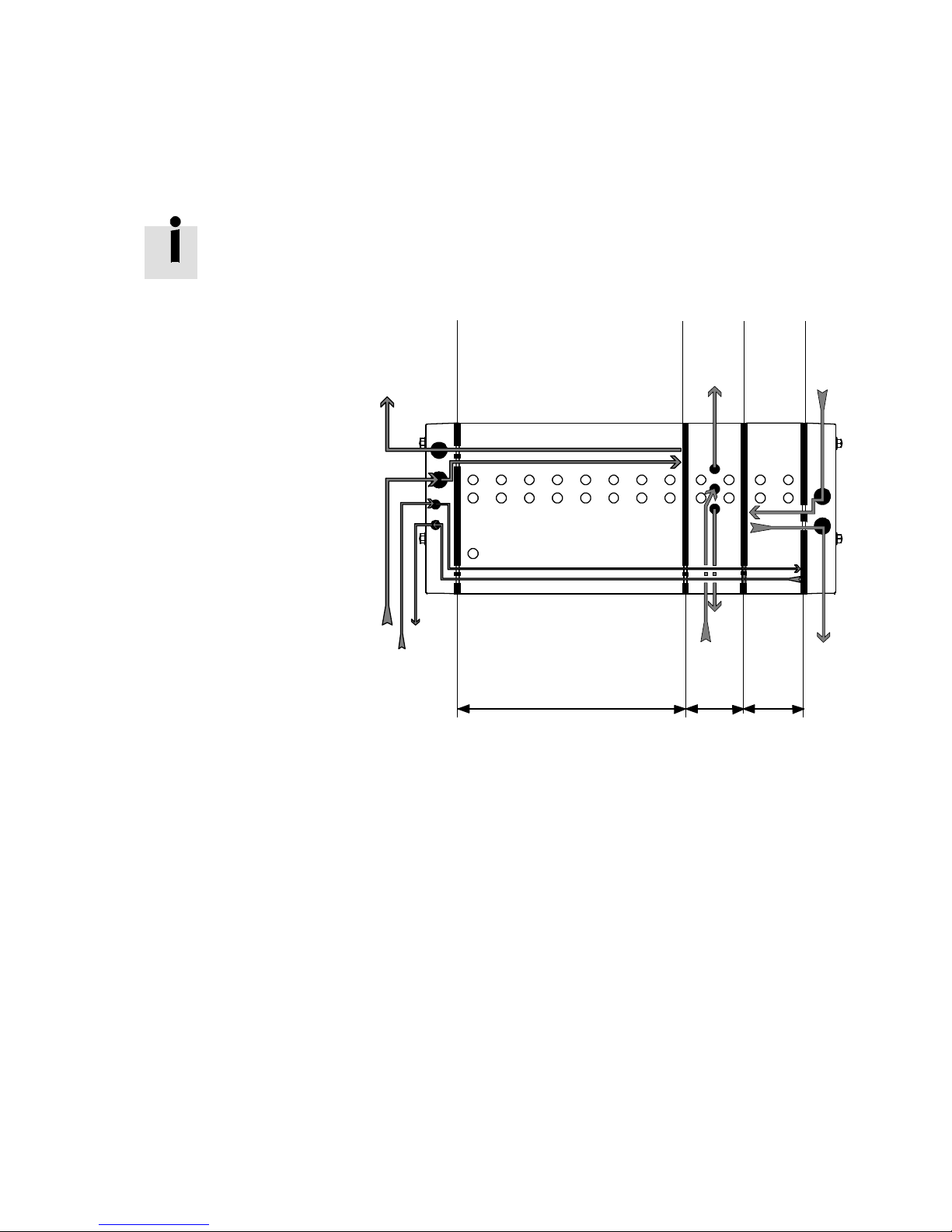
1
Separator plate
without channel
separation
2
Separator plate
with channel
separation
The separator plates with channel separation sit between
the manifold block and the expansion block as well as
between the expansion blocks.
121
3/5
2
3
1
5
82/84
1
12/14
Pressure zone 1
1
Pressure
zone 2
Pressure
zone 3
3/5
Fig. 3/4: Example: CDVI with 3 pressure zones (channel (1) and (3/5) blocked), external
supply of the second pressure zone, pilot control with external pilot air supply
Festo P.BE-CDVI-EN en 1202e
3-15
Page 54
3. Installation
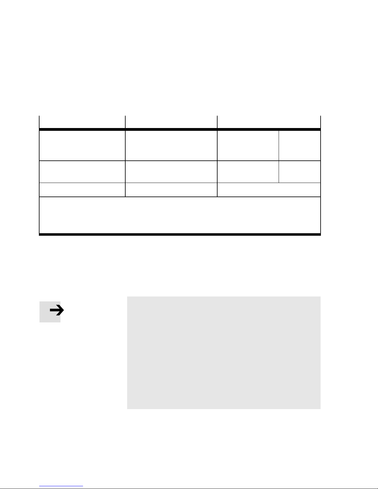
Note the following if the following separator plate combinations are used:
Separator plate pair
CDVI5.0-EB-DZP / ...-DZP EP-L andEP-R and EB-ZV EP-Lor EP-R
CDVI5.0-EB-DZP / ...-DZPR EP-Land EP-R and EB-ZV EP-L and EP-R Optional
CDVI5.0-EB-DZPR / ...-DZPR EP-L and EP-R and EB-ZV EP-L and EP-R and EB-ZV
EP-L = End plate left
EP-R = End plate right
EB-ZV = Expansion block with additional supply
Unused ports must be sealed.
Ventilation via Exhaust via
Other possibilities:
EP-Land EP-R
Optional
+EB-ZV
+EB-ZV
T ab. 3/4: Separator plate combinations for creating pressure zones
3.4.3 Operating the CDVI with vacuum/low pressure
3-16
Note
The valves with ident. code H, K and N (2x3/2-way valves)
are not permitted for operation with vacuum/low pressure.
A pneumatic spring takes over resetting these valves to the
normal position. This spring is operated with the operating
pressure (channel (1)). An operating pressure of at least 3
bar is required for resetting the valve.
•
Operate these valves in a separate pressure zone.
•
The operating pressure for this pressure zone must be
set in accordance with the diagram in appendix A,
Fig. A/1 .
Thefollowing requirements must be fulfilled so that you can
operate the CDVI at the supply port (1) with vacuum or low
pressure between -0.9...3 bar:
Festo P.BE-CDVI-E N en 1202e
Page 55
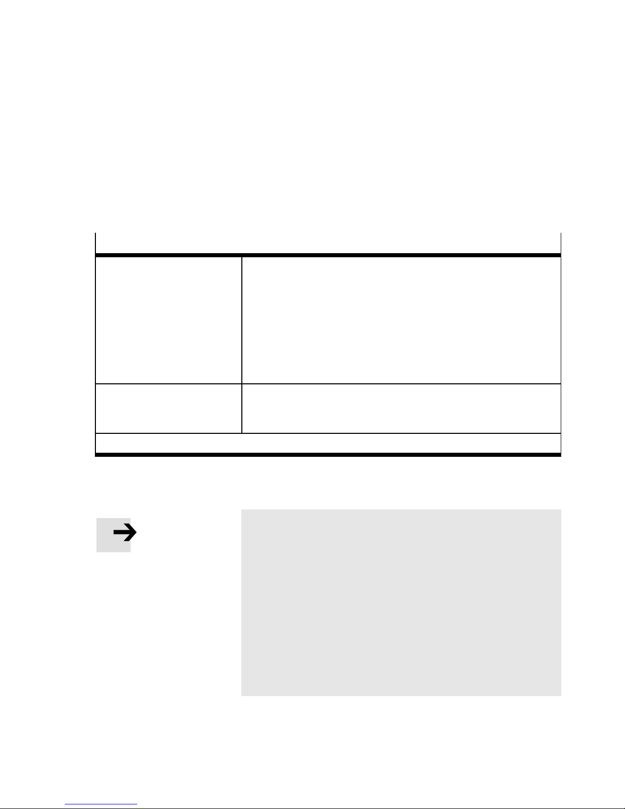
3. Installation
Valve sub-ba ses
– The pilot control of the solenoid coils is operated with
a regulated external pilot air supply.
– The valve terminal is fitted with the following valve sub-
bases and, in some cases has two pressure zones.
Pressure zone with vacuum or
low pressure supply
Pressure zone with excess
pressure supply
1)
In accordance with diagrams in Appendix A, Fig. A/1
1)
via port (1)
The pressure zone must be equipped only with the following valve
sub-bases:
– 5/2-way valve, monostable (ident. code M)
– 5/2-way valve, double solenoid (Ident. code J)
– 5/3-way valve (ident. code B, E and G )
– 3/2-way valve (Ident. code W and X) (see also subsequent note).
– 2/2-way valve (ident. code R and S)
The valve sub-bases with Ident. code N, K and H, if supplied via port
(1), are not suitable for vacuum/low pressure!
The pressure zone can additionally be equipped with the following
valve sub-bases:
– 2x3/2-way valves (Ident. code H, K and N)
Tab. 3/5: Valve sub-bases
Note
3/2-way valves with ident. code W and X:
2/2-way valves with ident. code R and S:
Festo P.BE-CDVI-EN en 1202e
– These valves can be supplied individually and therefore
operated in the pressure range of -0.9 … 10 bar. They are
independent of supply port 1 of the valve terminal. The
ports via which these valves are supplied with compressed air or vacuum and via which exhaust air is removed are shown in Appendix A, Tab. A/6, or Tab. A/7.
The above mentioned valves are supplied with pilot air via
port 12/14 of the valve terminal.
3-17
Page 56
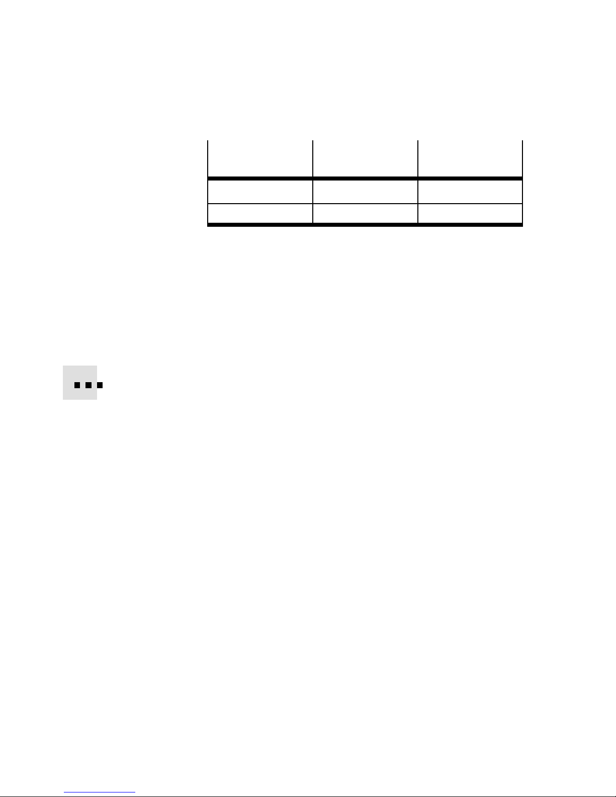
3. Installation
Directional control
valve
Ident. code R and X (4) (3)
Ident. code S and W (2) (5)
Tab. 3/6: Ports at the valves with ident. code R, S, X and W
3.5 Connecting the CDVI
3.5.1 Connecting the pneumatic lines
In the case of connecting plates fitted with blanking plates,
seal the working lines (2) and (4) with blanking plugs or
threaded blanking plugs to prevent dirt from entering.
For optimum efficiency of your terminal, the compressed air
supply and the exhausting should take place in the following
cases via the left and right-hand end plates:
Compressed air or
vacuum via port
Exhaust via port
3-18
– Onvalveterminalswithmorethan10valves(nominal
supply pressure 6 bar)
– On large capacity actuators:
Festo P.BE-CDVI-E N en 1202e
Page 57

3. Installation
Caution
Larger actuators or actuators operated simultaneously
(e.g. cylinders) can create a back pressure in the exhaust
duct of the valve terminal. The size of this back pressure
depends on the capacity of the ducted exhaust tubing.
This may lead to malfunctioning of the CDVI.
•
In this case, exhaust the CDVI via ports (3/5) on both
end plates and, if necessary, on the expansion block.
•
In order to avoid interactions with adjacent valves,
valves on expansion blocks can be separated by means
of a separate exhaust duct (3/5).
Note
Under certain circumstances, excess pressure can build up
under the valve covers of the CDVI. This pressure is reduced via the pressure compensation hole in the manifold
block.
•
Do not on any account plug the hole for the pressure
compensation.
•
Remove the excess pressure with ducted tubing. Do not
use any non-return valve in the line.
Note
Some ports have been covered with adhesive transparency
as protection against contamination.
•
Remove all adhesive transparencies from the ports.
•
Seal the following if not used:
– unused valve positions with blanking plates
– working ports (2), (4) with blanking plugs or plugs for
QSF plug connectors.
Festo P.BE-CDVI-EN en 1202e
3-19
Page 58
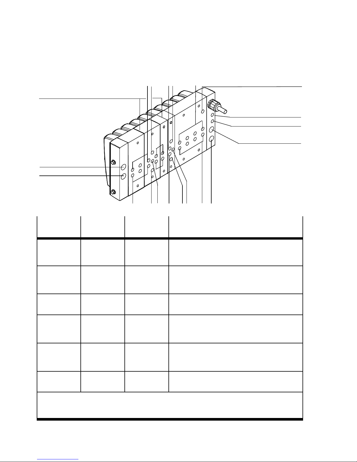
3. Installation
p
ansion block withports for
Ex
additional supply (optional)
3/5
1
Line Port code
(ISO 5599)
Compressed
air/vacuum
(1) G 3/8”
2
Port size
(ISO 228)
G 1/8”
5
4
2
13
Port threaded connector
– in the left/right end plate
– in the expansion block with auxiliary power
54
31
supply
4
3/5
2
Port (L) for pressure
compensation
82/84
12/14
1
1)
Air/vacuum (2), (4) G 1/8”
G 1/8”
Pilot air
supply
Exhaust air (3/5)
Exhaust air of
the pilot air
supply
Pressure compensation
1)
Depending on what you have ordered, the CDVI may already be fitted with QSF threaded
connectors.
2)
Note the instructions on pages 3-17 on connecting the pressure compensation.
(12/14) G 1/8” – in the left end plate
G 3/8”
(3), (5)
(82/84) G 1/8” – in the left end plate
------ G1/8” – in the manifold block
2)
G 1/8”
– in the manifold block
– in the expansion block with auxiliary power
supply
– in the left/right end plate
– in the expansion block with auxiliary power
supply
Tab. 3/7: Pneumatic ports of the CDVI
3-20
Festo P.BE-CDVI-E N en 1202e
Page 59
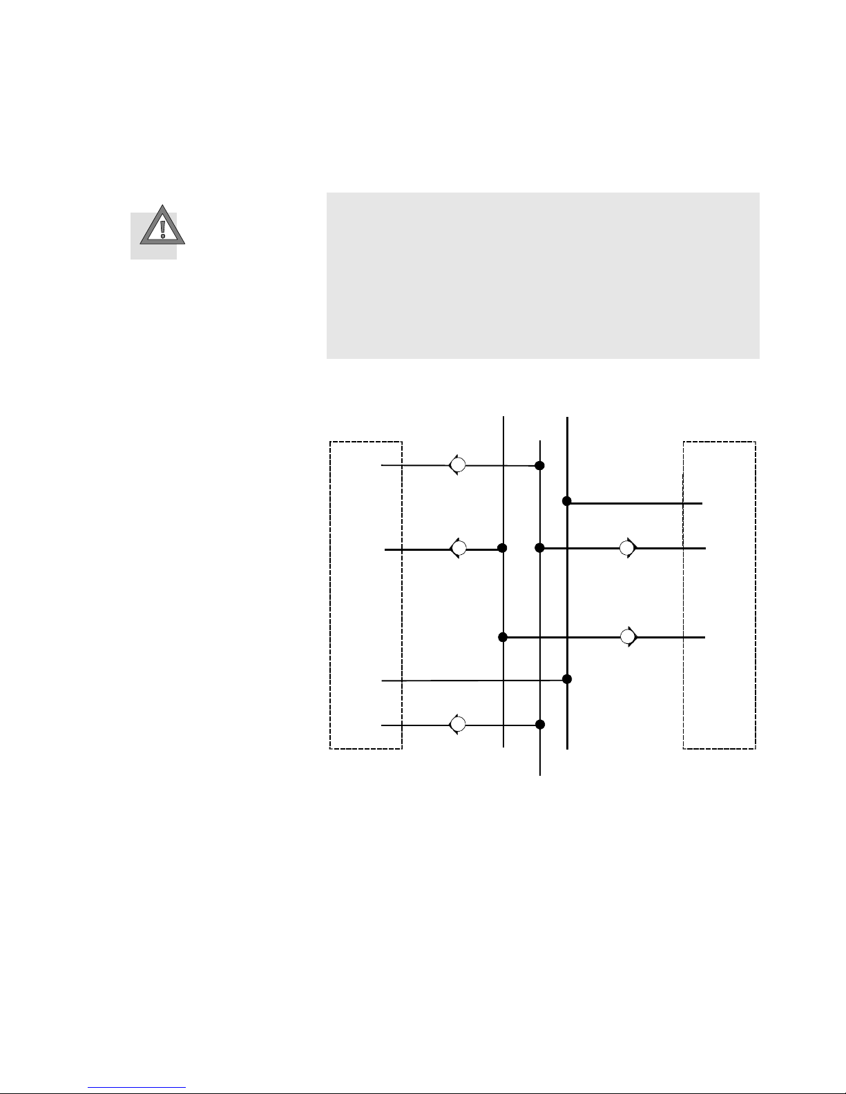
3. Installation
Caution
In the case of several systems with centrally ducted exhaust air, back pressures in the common exhaust tubing
(3/5) or (82/84) can lead to functional impairments of the
CDVI.
•
Use non-return valves in the common exhaust lines (3/5)
and (82/84).
System 1
Valve terminal
Central (82/84)
Common (3/5)
Common
(82/84)
Pressure
compen-
sation
Common (3/5)
Central pressure compensation
System 2
Pressure
compen -
sation
Common (3/5)
Common (82/84)
Valve terminal
Central (3/5)
Festo P.BE-CDVI-EN en 1202e
Fig. 3/5: Common lines with non-return valves
3-21
Page 60
3. Installation
3.5.2 Connecting the electric cables
Warning
•
Use for the electrical power supply only PELVcircuits in
accordance with IEC/DIN EN 60204-1 (Protective ExtraLow Voltage, PELV).
Also comply with the general requirements for PELV circuits in accordance with IEC/DIN EN 60204-1.
•
Use only powersources that guarantee reliable electrical
isolation of the operating voltage according to IEC/DIN
EN 60204-1.
By the use of PELV circuits, protection against electric shock
(protection against direct and indirect contact) is guaranteed
in accordance with IEC/DIN EN 60204-1 (electrical equipment
of machines, general requirements).
Note
Check within the framework of your EMERGENCY STOP
circuit, to ascertain the measures necessary for putting
your machine/system into a safe state in the event of an
EMERGENCY STOP (e.g. switching offthe operating voltage
for the valves and output modules, switching off the compressed air).
Note
Due to energy stored in the input circuitry of valve terminals, there may be a delayed reaction of the valves when the
load voltage is switched off. Take this into consideration,
e.g. as follows:
3-22
– Detect that the load voltage has been switched off by
means of an input signal in the controller.
– Block the control signal for the valves by locking the out-
put signal with the input signal “Load voltage”.
Festo P.BE-CDVI-E N en 1202e
Page 61

3. Installation
Detailed instructions on installing the electrical connections
oftheCDVI-MPcanbefoundintheleaflettypeP.BE-K-CDVI
supplied with the product.
Detailed instructions on wiring the electrical connections of
the CDVI with DI connection “DeviceNet” can be found in the
electronics manual P.BE-CDVI-DN-...
Earthing the CD VI
Note
Interference from electromagnetic sources.
•
Earth your CDVI. Make sure that there is a conductive
connection (low impedance, short cable with large cross
section) between the CDVI and the earth potential.
3.6 Address assignment of the valves
Detailed instructions on addressing CDVI with DI connection
“DeviceNet” can be found in the electronics manual
P.BE-CDVI-DN-...
The CDVI occupies 16 or 24 addresses, depending on the
number of valve positions, irrespective of the types of valves
fitted. This enables the CDVI valve terminal to be extended at a
later date without the need to shift the addresses.
– Addresses should be allocated in ascending consecutive
order.
– Counting begins on the CDVI from left to right, but on
the individual valve positions from right to left.
Festo P.BE-CDVI-EN en 1202e
– A valve position on the CDVI valve terminal always
occupies 2 addresses, even if it is only fitted with a
blanking plate.
3-23
Page 62
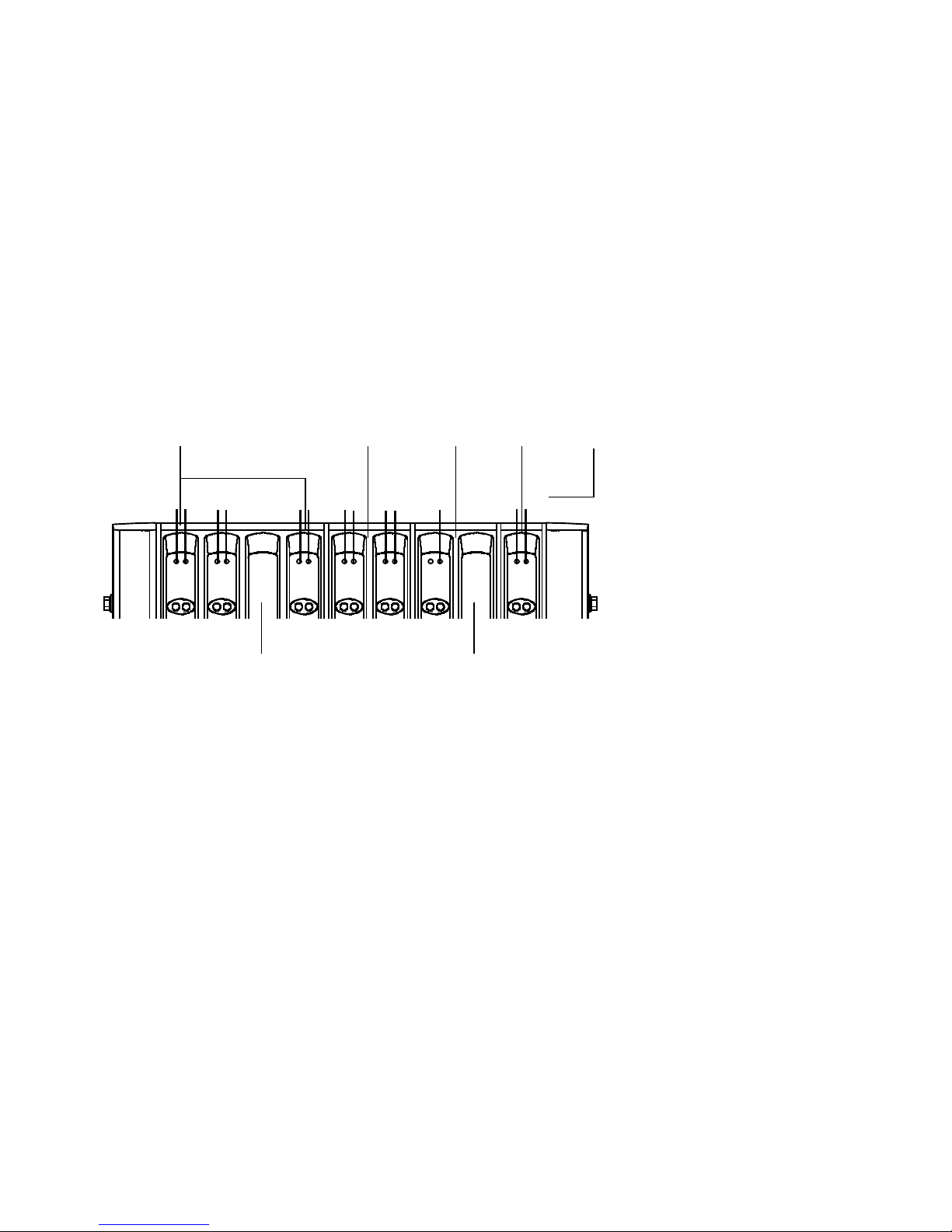
3. Installation
– In the case of valves with two solenoids coils, solenoid
coil 14 occupies the less significant address and solenoid
coil 12 occupies the higher-value address.
– In the case of valves with only one solenoid coil, the
higher-value address remains unused.
The following diagram shows the addressing sequence using
the example of the CDVI with 9 valve positions.
4
1415
1214
01
12 14
3456
2
1214
12 14
3215
7
9
8
1011 12 13
1214 14
1214
67
1
4-valve manifold block
2
2-valve Bi-expansion block
5
Addresses of the solenoid coils
6
Vacant position on Mo-expansion block
(occupies 1 address)
3
2-valve Mo-expansion block
7
Vacant position on 4-valve manifold
4
1-valve Bi-expansion block
block (occupies 2 addresses)
Fig. 3/6: Example: Address assignment of the CDVI with MP connection
3-24
Festo P.BE-CDVI-E N en 1202e
Page 63

Commissioning
Chapter 4
Commissioning
Festo P.BE-CDVI-EN en 1202e
4-1
Page 64

4. Commissioning
Contents
4. Commissioning 4-1................................................
4.1 Instructions on commissioning 4-4....................................
4.1.1 Before commissioning 4-4....................................
4.1.2 Pressure increase in the overall supply 4-4......................
4.2 Checking the valves and the valve-actuator combination 4-6...............
4.2.1 Manual override 4-6.........................................
4.2.2 Checking 4-7..............................................
4.3 LED displays of the valves 4-10........................................
4.4 Troubleshooting 4-11................................................
4.4.1 Impairment of function 4-11...................................
4.4.2 Operating status of the pneumatic system 4-12...................
4-2
Festo P.BE-CDVI-E N en 1202e
Page 65

4. Commissioning
Contents of this chapter This chapter deals with the commissioning of the CDVI. This
includes in particular the following:
– Instructions on building up pressure in the overall supply
– Checking the valves and the valve-actuator combination
– The function of the manual overrides
– Troubleshooting
– Assignment of the LEDs
Further information Instructions on diagnosing and troubleshooting on the
CDVI with DI connection “DeviceNet” can be found in
the Electronics Manual P.BE-CDVI-DN-...
Festo P.BE-CDVI-EN en 1202e
4-3
Page 66

4. Commissioning
4.1 Instructions on commissioning
4.1.1 Before commissioning
•
Switch off the power supply before connecting or disconnecting plugs (otherwise this could lead to functional
damage).
•
Commission only a valve terminal which has been fitted
and wired completely.
•
Make sure that there is a sufficient supply of fresh air
(cooling) for the following operating conditions:
– When the maximum number of valves are fitted
– When the maximum operating voltage is applied
– When the solenoid coil is constantly under stress
•
Please observe the following instructions on building up
pressure in the overall supply.
4.1.2 Pressure increase in the overall supply
Warning
If the pressure build-up of the pilot air supply is too slow
or delayed, this may cause the actuators to perform
sudden unexpected movements under the following conditions:
– When the compressed air is connected via a soft-start
valve (gradual pressure build-up) and
– When there are electric signals (e.g. after EMERGENCY
STOP).
This can cause damage to the machine or system and even
injury to persons.
•
Operate the valve terminal with an external pilot air supply (3 ... 8 bar). Branch the pilot air supply before the
soft-start valve (see Fig. 4/1).
4-4
Festo P.BE-CDVI-E N en 1202e
Page 67
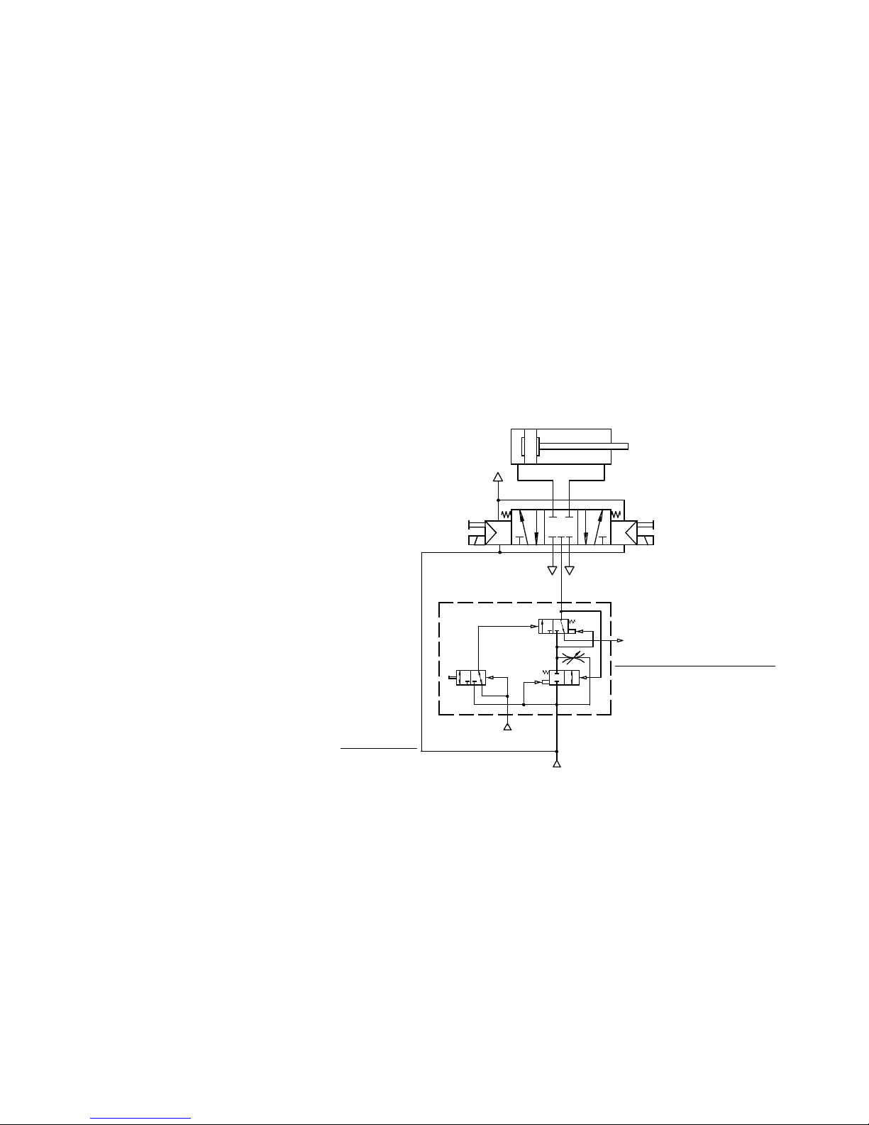
4. Commissioning
The pilot air must be applied with a pressure of 3 ... 8 bar
immediately after being switched on, otherwise there is no
guarantee that the valve will reverse directly (see diagram).
If the pressure is less than 3 bar, there may be a delay before
the valve reverses, in spite of an electric signal. The gradual
pressure build-up of the overall supply does not affect the
actuator in that case. The actuator would react suddenly
(e.g. a cylinder would extend or retract suddenly, depending
on the valve function).
82/84
42
14 12
12/14
1
1
Externally supplied pilot air (3 ... 8 bar), branched
12/14
1
53
2
3
1
before the soft-start valve
2
Festo P.BE-CDVI-EN en 1202e
2
Soft-start valve (gradual pressure build-up of the
overall supply)
Fig. 4/1: Example of valve-cylinder combination with gradual
pressure build-up of the overall supply
4-5
Page 68

4. Commissioning
The table below shows the effects of slow start-up pressurisation when there are electric signals:
External pilot air
supply
Pressure rise in
overa l l supply
Pressure rise
in the pilot air
Time when a
valve reverses
supply (12/14)
branched after the
soft-start valve
branched in front of
the soft-start valve
slow slow after pressure
rise at (1)
slow fast before pressure
rise at (1)
Tab. 4/1: Effects of slow start-up pressurisation
4.2 Checking the valves and the valve-actuator combination
4.2.1 Manual override
You should use the manual override especially when commissioning the pneumatic system, in order to check the function and
operation of the valve or the valve-actuator combination.
Movement
of the
actuator
fast
slow
4-6
By actuating the manual override, you can switch the valve
without an electric signal. You only need to switch on the
compressed air supply.
The manual override has been designed to be used as follows:
Manual override design
Manual override with automatic
return (pushing)
Mode of operation
The manual override is reset
automatically by spring force.
Tab. 4/2: Actuation types of the manual override
Festo P.BE-CDVI-E N en 1202e
Page 69
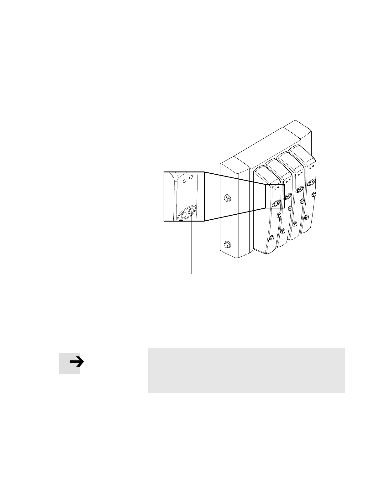
4. Commissioning
1
MO for solenoid
coil 14
2
MO for solenoid
coil 12
The assignment of the manual overrides to the solenoid coils
is as follows:
2
Fig. 4/2: Position of the manual overrides
4.2.2 Checking
Note
Before commissioning the CDVI, note the specifications
on the medium, see chapter “Installation,” section “Pilot
air supply.”
Proceed as follows when commissioning the valve terminal:
1
Festo P.BE-CDVI-EN en 1202e
4-7
Page 70
4. Commissioning
Commissioning variant Activity
Preliminary test of the
pneumatic tubing
Complete commissioning
oftheentiresystem
Checking the valve-actuator
combination by means of the
manual override (MO)
Installing and connecting the
entire system.
Program control via PLC/
industrial PC.
T ab. 4/3: Commissioning variants
Commissioning by means of the manual override is described
below.
Warning
Before actuating the MO:
Uncontrolled actuation of solenoid coils can cause the
actuators to perform sudden unexpected movements
which may cause personal injury and material damage.
•
Disconnect the operating voltage supply for the solenoid
coils from the relevant connections on the valve
terminal.
4-8
•
Actuate the MOs only with a blunt object
This avoids unintentional actuation of the valve solenoid
coils and damage to the MOs.
Before switching on the power supply:
During commissioning, manual override functions which
are in the switched state can cause actuators to perform
sudden unexpected movements. These movements can
cause injury to persons and damage to property.
•
Make sure that all manual override actuations are reset
to their basic positions.
You will thereby avoid undefined switching states of the
valves.
Festo P.BE-CDVI-E N en 1202e
Page 71
4. Commissioning
Procedure:
Warning
Before testing the valve-actuator combination:
– Make sure that nobody is in the danger zone.
Note
A valve which has been switched by an electric signal (in
switch position), cannot be reset to the normal position by
actuation of the manual override. The electric signal is
dominant in this case.
•
Reset the electric signal before actuating the manual
override.
1. Switch on the compressed air supply.
2. Check the functioning and effect of each valve-actuator
combination by actuating the relevant manual override.
3. Make sure that all valves are in the normal position before
commissioning the valve terminal.
4. Switch off the compressed air supply after testing the
valves.
Festo P.BE-CDVI-EN en 1202e
4-9
Page 72
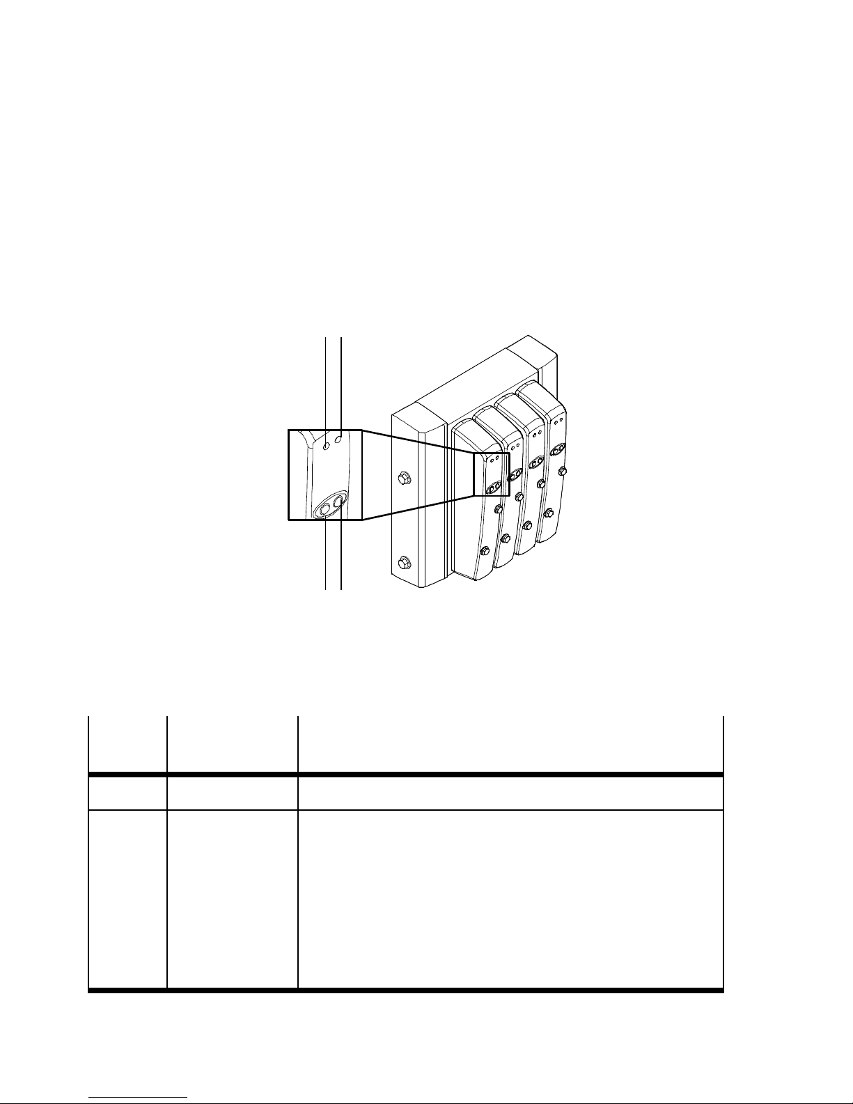
4. Commissioning
4.3 LED displays of the valves
There is a yellow LED for every solenoid coil. This LED shows
the switching status of the solenoid coil. The position of the
LED and the manual override to the appropriate solenoid coil
is as follows:
21
1 2
Yellow LED and MO for solenoid coil 12
1
2
Yellow LED and MO for solenoid coil 14
Fig. 4/3: Assignment of the LED and MO to the solenoid coil
LED
Dark Normal position Logical 0 (signal not applied)
lLghts up
yellow
Switching position of the valve
–
Switched
position
or
–
Normal position
Meaning/possible cause if the valve does not switch
Logical1(signalispresent)
Logical 1 but:
–
The operating voltage of the outputs lies outside the permitted
tolerance range (21.6 ... 26.4 V DC) or
–
The compressed air supply is not OK or
–
The pilot exhaust is blocked or
–
the pilot air supply is outside the range of 3 ... 8 bar or
–
Servicing required
Tab. 4/4: Meaning of the LED display
4-10
Festo P.BE-CDVI-E N en 1202e
Page 73

4. Commissioning
4.4 Troubleshooting
4.4.1 Impairment of function
After switching on the compressed air supply or when
subsequently testing the individual valves, you can learn
the following about the operating status of the pneumatic
system:
Operating status of the
pneumatic system
Valve position Error handling when the
compressed air supply has been
switched off
Air escapes from ...
–
Bus line connections
–
Working line connections
Air flows out between the modules Normal position • After switching on again, regulate the
Pressure drop or resonance
noises
Valve or pneumatic system doe s
not react as expected
Valve or pneumatic system doe s
not react
–
Normal
position
–
Switching
position
Normal position • Fitting the CDVI directly onto the
Switching
position
Switching
position
• Check the sealing ring or the tubing
(if necessary, grease slightly)
external pilot air to 3 ... 8 bar.
mounting surface without using the
spacer bolts
• Check the tubing lines
• After restarting, check the operating
pressure (if necessary for each press
ure zone).
• Servicing required
Tab. 4/5: Function impairment of the pneumatic system
Festo P.BE-CDVI-EN en 1202e
Normal position • If the CDVI is operated with regulated
external pilot air, check the pilot
pressure at the regulator connection
when the compressed air is switche d on
again (apply pressure , 3 bar at
regulator)
4-11
Page 74

4. Commissioning
4.4.2 Operating status of the pneumatic system
If the operating status of the pneumatic system deviates from
the desired pneumatic operating status, the following
conditions are probably not fulfilled:
Desired pneumatic
Requirement Remarks
operating status
zero-leakage
fast reaction sufficient pressure supply CDVI with one pressure zone:
trouble-free Non-return valves in common
Several pressure zones Limiting the pressure zones on
Vacuum operation / low
pressure operation
–
Tubing connected with care
–
Regulated external pilot air
(3 ... 8 bar).
exhaust tubing
both sides by means of separator
plates
Separately supplied regulated
pilot air (3 ... 8 bar)
Supply or remove compressed air
and exhaust air via the left and
right-hand end plate.
This applies when several systems
with centrally ducted exhaust are
used
Subsequent conversion possible
(see c hapter 5)
–
Vacuum operation not possible
with 2 x 3/2-wa y valves
–
External regulator can only
be operated with pressure
(, 3bar)
EMERGENCY STOP of
pressure zones
Slow start-up pressurization after EMERGENCY
STOP
Guaranteeing the controller
function for the pilot air supply
despite the overall supply being
switched off
–
–
Tab. 4/6: Pneumatic operating states
4-12
Using the right-hand end plate
for external pilot air supply
Re-pressurizing the CDVI via
the soft-start valve
The controller regulates the pilot
air supply of all the valves on the
CDVI
If electrical control signals are
present, the pilot air supply
must have a pressure of 3 ... 8 bar
immediately after switching on.
Festo P.BE-CDVI-E N en 1202e
Page 75

Cleaning, maintenance and conversion
Chapter 5
Cleaning, maintenance and conversion
Festo P.BE-CDVI-EN en 1202e
5-1
Page 76

5. Cleaning, maintenance and conversion
Contents
5. Cleaning, maintenance and conversion 5-1............................
5.1 Cleaning the CDVI 5-4...............................................
5.2 General preventive action 5-6........................................
5.3 Dismantling/fitting the CDVI 5-8......................................
5.4 Replacing valve terminal components 5-9..............................
5.4.1 Valves and blanking plates 5-9................................
5.5 Extension and conversion of the valve terminal 5-11.......................
5.5.1 Expansion block 5-11.........................................
5.5.2 Pilot air supply 5-14..........................................
5.5.3 Pressure zones 5-16.........................................
5.5.4 End plates 5-21.............................................
5-2
Festo P.BE-CDVI-E N en 1202e
Page 77

5. Cleaning, maintenance and conversion
Contents of this chapter This chapter describes maintenance and conversion of the
CDVI. This includes in particular the following:
– Cleaning the CDVI
– Replacing valve plates or blanking plates
– Adding valve positions
– Adding pressure zones
– Fitting and removing the end plates
Additional information Instructions on connecting the electric components of the
CDVI with MP connection can be found in the information
supplied with the product.
Instructions on connecting the electric components of the
CDVI with DI connection “DeviceNet” can be found in the
manual CDVI-DN (P.BE-CDVI-DN-...).
Festo P.BE-CDVI-EN en 1202e
5-3
Page 78

5. Cleaning, maintenance and conversion
5.1 Cleaning the CDVI
The CDVI from Festo is a valve terminal especially for the
splash range in the food and packing industry. It features in
particular the following:
– Increased resistance to corrosion
– Resistance to acid and alkaline cleaning agents
– Compliance with relevant protection classes (see Appen-
dix A “Technical data”).
– Easy to clean.
Caution
Disinfectants may contain substances which can damage
the components of the CDVI in the long or short term
(e.g. sodium hypochlorite).
– Avoid using cleaning agents with a sodium hypochlorite
basis.
– Do not disinfect the CDVI with ultra-violet light.
– Note that the IP protection class refers to cold water
without cleaning agents. Cleaning agents can reduce
the surface tension.
In individual cases you should consult the manufacturer
of the cleaning agent/disinfectant regarding its compatibility with the CDVI.
5-4
Festo P.BE-CDVI-E N en 1202e
Page 79

5. Cleaning, maintenance and conversion
Clean the valve terminal as follows:
– Use aluminium-compatible cleaning agents (e.g. from
Henkel Ecolab, Diversy Lever or Kärcher)
Use the cleaning agent in the concentration, at the processing
temperature and in an environmentally friendly manner according to the specifications of the manufacturer (see data
sheet), but not at a processing temperature over +50°C.
•
After cleaning rinse the CDVI with plenty of clear water, so
that the cleaning agent cannot dry. Otherwise there will be
“increased concentration” which may damage the surface
of the CDVI.
Festo P.BE-CDVI-EN en 1202e
5-5
Page 80

5. Cleaning, maintenance and conversion
5.2 General preventive action
Warning
Uncontrolled movements of the connected actuators and
uncontrolled movements of loose tubing can cause injury
to persons and/or damage to property.
•
Make sure that the higher-order controller has not sent
control signals to the solenoid coils.
•
Before carrying out conversion work on the CDVI, switch
off the following:
– The compressed air supply
– The power supply
The CDVI is supplied pre-assembled from the factory. If you
wish to supplement or replace individual components, please
note the following:
5-6
Festo P.BE-CDVI-E N en 1202e
Page 81
5. Cleaning, maintenance and conversion
Note
Handle all the components of the CDVI with great care.
Note especially the following when mounting components:
•
Screws must be fitted accurately (otherwise threads will
be damaged).
•
Screws must be fastened only by hand. Screws must be
fitted so that the self-cutting threads can be used.
•
The specified torques must be observed.
•
Threaded connections must be mounted free of offset
and mechanical tension.
•
Avoid an offset between the components, otherwise the
protection class requirements may no longer be fulfilled
(see Appendix A, “T echnical data”).
•
Check the seals for damage before fitting (IP 65).
•
Make sure that the connecting surfaces are clean
(avoid leakage and contact errors).
•
In the case of components ordered at a later date,
observe also the fitting instructions supplied.
Caution
Components may be damaged if they are not handled
correctly.
•
Observe the handling specifications for electrostatically
sensitive devices.
•
Discharge yourself of static electricity before fitting or
removing the components in order to protect the
modules against static discharges.
•
Do not touch the contact surfaces of the plug connectors
on the sides of the components.
Festo P.BE-CDVI-EN en 1202e
5-7
Page 82

5. Cleaning, maintenance and conversion
5.3 Dismantling/fitting the CDVI
Provided that the CDVI is easily accessible, it need not be
dismantled when the following components are replaced or
removed:
– Valves or blanking plates
– Expansion block
– End plates
Dismantling Proceed as follows:
1. If spacer bolts are used, remove these from the mounting
surface.
2. Disconnect the tubing at the working lines (2/4), at the
supply ports (1, 12/14), at the pressure compensation
port (L), and at the exhaust ports (3/5, 82/84) (see
chapter 3.2 “General connection technology”)
3. Disconnect the electrical connections:
CDVI with MP connection:
Loosen the electric multi-pin by removing the left-hand
end plate (see section 5.5.4 “End plates”).
CDVI with DI connection:
Disconnect the electrical connections of the CDVI with DI
connection(seeappropriatemanualfortheCDVIwith
fieldbus direct connection).
Assembly Proceed as follows:
1. Connect the electric multi-pin by fitting the left-hand end
plate (see section 5.5.4 “End plates”).
5-8
2. Install the pneumatic ports (see chapter 3.2 “General
connection technology”)
3. Mount the CDVI on its mounting surface (see chapter 2
“Assembly”)
Festo P.BE-CDVI-E N en 1202e
Page 83

5. Cleaning, maintenance and conversion
5.4 Replacing valve terminal components
5.4.1 Valves and blanking plates
The valves and blanking plates of the CDVI can easily be
replaced or added.
All valve positions on the CDVI support triggering two solenoid coils.
Dismantling Proceed as follows:
1. Clean and dry the CDVI so that the surfaces of the
in-line manifolds are clean.
2. Undo the mounting screws of the components
(see Fig. 5/1). Pay attention to the O-rings used as
locking agent.
3. Carefully pull the component off the in-line valve manifold.
Assembly Proceed as follows:
1. Check the valves to make sure that they are inserted as
far as possible into the valve cover.
2. Carefully plug the component onto the in-line valve manifold. Pay particular attention to the terminal lugs on
valves; these are not resistant to bending in alternate
directions.
Festo P.BE-CDVI-EN en 1202e
3. Tighten the mounting screws with max. 0.8 Nm (-0.1 Nm).
5-9
Page 84
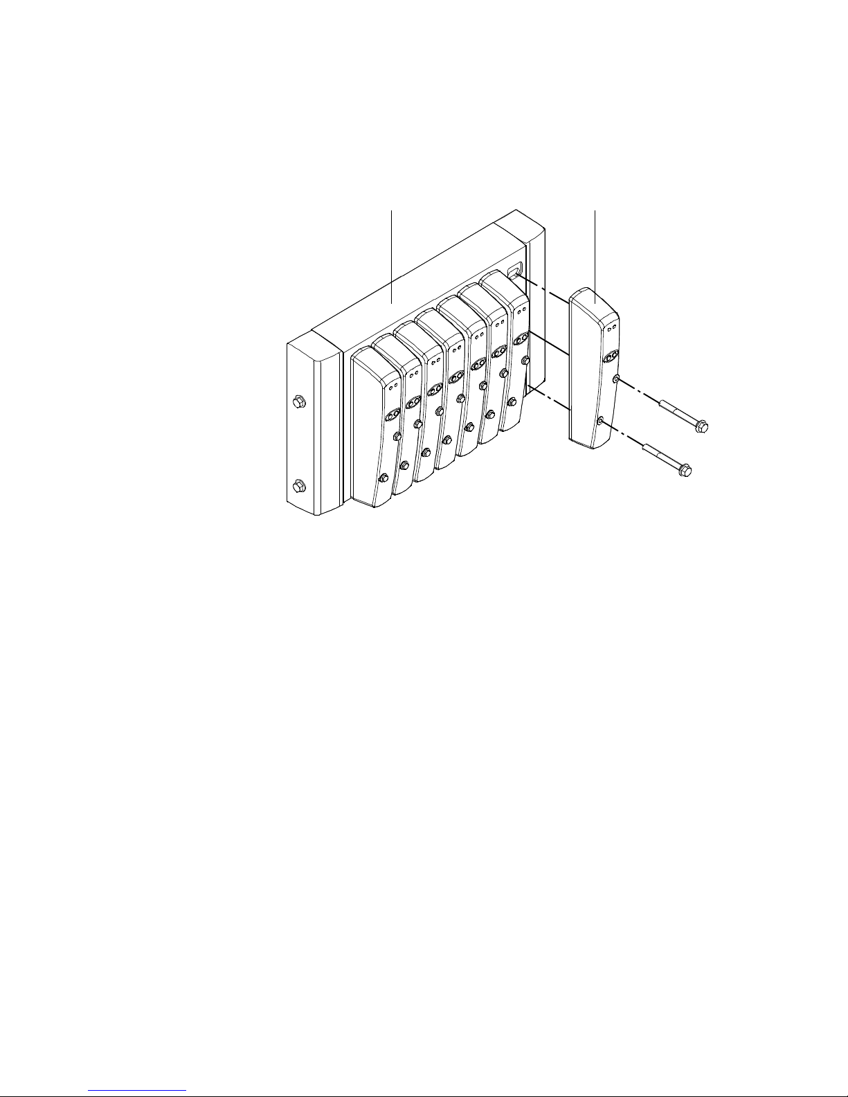
5. Cleaning, maintenance and conversion
1
In-line manifold
block
2
Valve
12
Fig. 5/1: Assembling/removing valves
5-10
Festo P.BE-CDVI-E N en 1202e
Page 85

5. Cleaning, maintenance and conversion
5.5 Extension and conversion of the valve terminal
5.5.1 Expansion block
T o facilitate mounting the expansion block, Festo recommends that you dismantle the CDVI from the mounting surface.
If the CDVI is easily accessible, the expansion block can also
be fitted without the need for you to dismantle the valve terminal. Combinations of Bi- and Mo-expansion blocks are permissible. In the extension, at the most 8 solenoid coils can be
triggered.
– You can extend the CDVI by maximum
– 4 valve positions (when using exclusively Bi-expan-
sion blocks) or by
– 8 valve positions (when using exclusively Mo-expan-
sion blocks).
– When extending the CDVI, it is not possible to use
manifold blocks because screwing together multiple
manifold blocks has not been provided for in the design.
– In order to extend the CDVI, please use the components
listed in the following table.
Note
With more than 2 pressure zones:
Ensure that there is a corresponding pneumatic supply
port for each pressure zone.
Festo P.BE-CDVI-EN en 1202e
5-11
Page 86

5. Cleaning, maintenance and conversion
For extending the CDVI, you will require the following components:
Component
Electrical connection variant of the CDVI
CDVI-MP CDVI-FB
Without
additional
electr . supply
Expansion block: CDVI5.0- CDVI5.0- CDVI5.0-
for CDVI with 2 pressure zones
–
Standard expansion block
for CDVI with 3 or more pressure zones
–
Standard expansion block for the
pressure zone on the outside right
per internal pressure zone
–
one expansion block with additional
pneumatic supply code X
-EB1-MP...
or
-EB2-MP-...
-EB1-MP-...
or
-EB2-MP-...
-EB1X-MP-...
or
-EB2X-MP-...
-EB1-DN-...
or
-EB2-DN-...
-EB1-DN-...
or
-EB2-DN-...
-EB1X-DN-...
or
-EB2X-DN-...
With additional
electr . supply
(code Z)
-EB1Z-DN-...
or
-EB2Z-DN-...
-EB1Z-DN-...
or
-EB2Z-DN-...
-EB1XZ-DN-...
or
-EB2XZ-DN-...
Separator plates:
one separator plate per expansion block:
–
Without channel separation
–
Channel 1 blocked
–
Channel 3/5 blocked
–
Channels 1 and 3/5 blocked
Corresponding number of valves For an overview of the valve types, see chapter 1,
One blanking plate per unused valve
position
Tab. 5/1: Components for extending valve terminals
5-12
CDVI5.0-EB-DZ
CDVI5.0-EB-DZP
CDVI5.0-EB-DZR
CDVI5.0-EB-DZPR
Tab. 1/4
CDVI5.0-AP-2
Festo P.BE-CDVI-E N en 1202e
Page 87

5. Cleaning, maintenance and conversion
Procedure:
1. Please observe the general preventive actions
(see section 5.2).
2. Dismantle the CDVI if necessary (see section 5.3).
Inserting expansion blocks
3. Remove the right-hand end plate (see section 5.5.4
“End plates”).
4. Place a separator plate, if necessary with pressure zone
separation (see section 5.5.3 “Pressure zones”), onto the
guide sleeves of the expansion block.
5. Place the expansion block next to the manifold block
(see Fig. 5/2).
6. Repeat point 2 if you wish to mount a second expansion
block. Place this expansion block next to the first expansion block.
7. Assemble the right-hand end plate (see section 5.5.4
“End plates”). Make sure that the individual screw length
matches the extension.
Festo P.BE-CDVI-EN en 1202e
5-13
Page 88
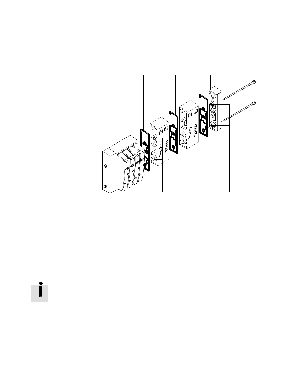
5. Cleaning, maintenance and conversion
1
Manifold block
2
Separator plate
without channel
separation
3
Standard
expansion block
4
Right-hand end
plate
5
Guide sleeves
12 32243
Fig. 5/2: Adding valve positions on the CDVI without pressure zones
8. Fit the CDVI (see section 5.3).
5.5.2 Pilot air supply
By fitting the appropriate right-hand end plate, you can operate your CDVI with internally branched or externally supplied
pilot air .
Mixed operation of the CDVI with internal and external pilot
air supply is not intended. The optionally available separator
plates do not separate the pilot air supply channel.
555
5-14
Festo P.BE-CDVI-E N en 1202e
Page 89

5. Cleaning, maintenance and conversion
You will require the following components:
Components
Right-hand end plate CDVI5.0-EPR CDVI5.0-EPR-S
Blanking plug for connection 12/14 CDVI5.0-B-G1/8 --------------------
Internal pilot
air supply
External pilot
air supply
Tab. 5/2: Components for conversion to internal or external pilot air supply
T o facilitate mounting the end plate, Festo recommends that
you dismantle the CDVI from its mounting surface. If the CDVI
is easily accessible, conversion of the end plate can also be
undertaken without the need for you to dismantle the valve
terminal.
Procedure:
1. Please observe the general preventive actions
(see section 5.2).
2. Dismantle the CDVI if necessary (see section 5.3).
Festo P.BE-CDVI-EN en 1202e
3. Exchange the end plate (see section 5.5.4 “End plates”)
4. Fit the CDVI if necessary (see section 5.3).
5-15
Page 90

5. Cleaning, maintenance and conversion
5.5.3 Pressure zones
The CDVI with one pressure zone can be converted at a later
stage to operation with up to nine pressure zones.
You will require the following components:
Components
One of the following separator plates:
–
Channel 1 blocked
–
Channel 3/5 blocked
–
Channels 1 and 3/5 blocked
One or two expansion blocks See this chapter,
possibly blanking plug
–
For por ts 1 or 3/5
–
For por ts 12/14, 82/84 or 2/4
Type
CDVI5.0-EB-DZP
CDVI5.0-EB-DZR
CDVI5.0-EB-DZPR
Tab. 5/1
CDVI5.0-B-G3/8
CDVI5.0-B-G1/8
Tab. 5/3: Components for creating pressure zones
Procedure:
1. Please observe the general preventive actions
(see section 5.2).
2. Dismantle the CDVI (see section 5.3).
5-16
3. Insert the separator plate and if necessary the expansion
block as described below.
4. Fit the CDVI (see section 5.3).
Note
•
Seal unused pneumatic por ts (pilot air supply ports)
with a blanking plug.
Festo P.BE-CDVI-E N en 1202e
Page 91

5. Cleaning, maintenance and conversion
Inserting the separator plate and, if necessary, an expansion block
CDVI with two pressure zones
Note
CDVI with two expansion blocks and two pressure zones:
– Channel (1) or channels (3) and (5) may only be
separated once.
– If during pressure zone separation, channel (1) and
channels (3) and (5) are separated, this can be accomplished as follows:
– At a common position by means of the separator plate
type CDVI5.0-EB-DZPR.
– At a common position by means of the separator plate
type CDVI5.0-EB-DZP and at a further position by
means of the separator plate type CDVI5.0-EB-DZR.
1. Remove the right-hand end plate (see section 5.5.4
“End plates”).
2. Insert the appropriate separator plate into the guide
sleeves of the standard expansion block.
3. Place the standard expansion block next to the manifold
block (see Fig. 5/3).
4. Repeat point 2 if your CDVI is fitted with a second expansion block. Place this expansion block next to the first
expansion block.
5. Assemble the right-hand end plate (see section 5.5.4
“End plates”).
Festo P.BE-CDVI-EN en 1202e
5-17
Page 92
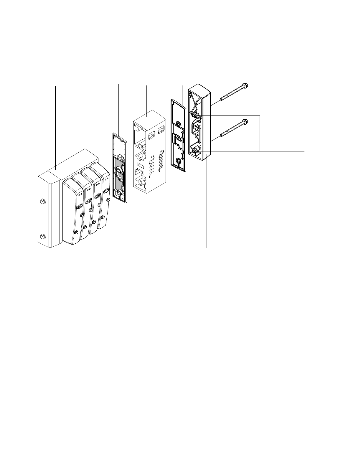
5. Cleaning, maintenance and conversion
1
2
34
5
6
1
Manifold block
2
Separator plate with channel
separation
3
Standard expansion block
Fig. 5/3: Example: Fitting the separator plates on the CDVI with 2 pressure zones
4
Separator plate without channel
separation
5
Guide sleeves
6
Right-hand end plate
5-18
Festo P.BE-CDVI-E N en 1202e
Page 93
5. Cleaning, maintenance and conversion
CDVI with three pressure zones
Note
The expansion block with additional supply (second pressure zone) must be fitted between the manifold block and
the standard expansion block (see Fig. 5/4).
1. Remove the right-hand end plate (see section 5.5.4
“End plates”).
2. Insert the appropriate separator plate (with channel
separation) for the second pressure zone into the guide
sleeves of the expansion block with additional supply
(first expansion block, see Fig. 5/4).
3. Place the expansion block with additional supply next
to the manifold block.
4. Insert the appropriate separator plate (with channel
separation) for the third pressure zone into the guide
sleeves of the standard expansion block (second expansion block).
5. Finally, place the standard expansion block next to the
expansion block with additional supply.
6. Assemble the right-hand end plate (see section 5.5.4
“End plates”).
Festo P.BE-CDVI-EN en 1202e
5-19
Page 94
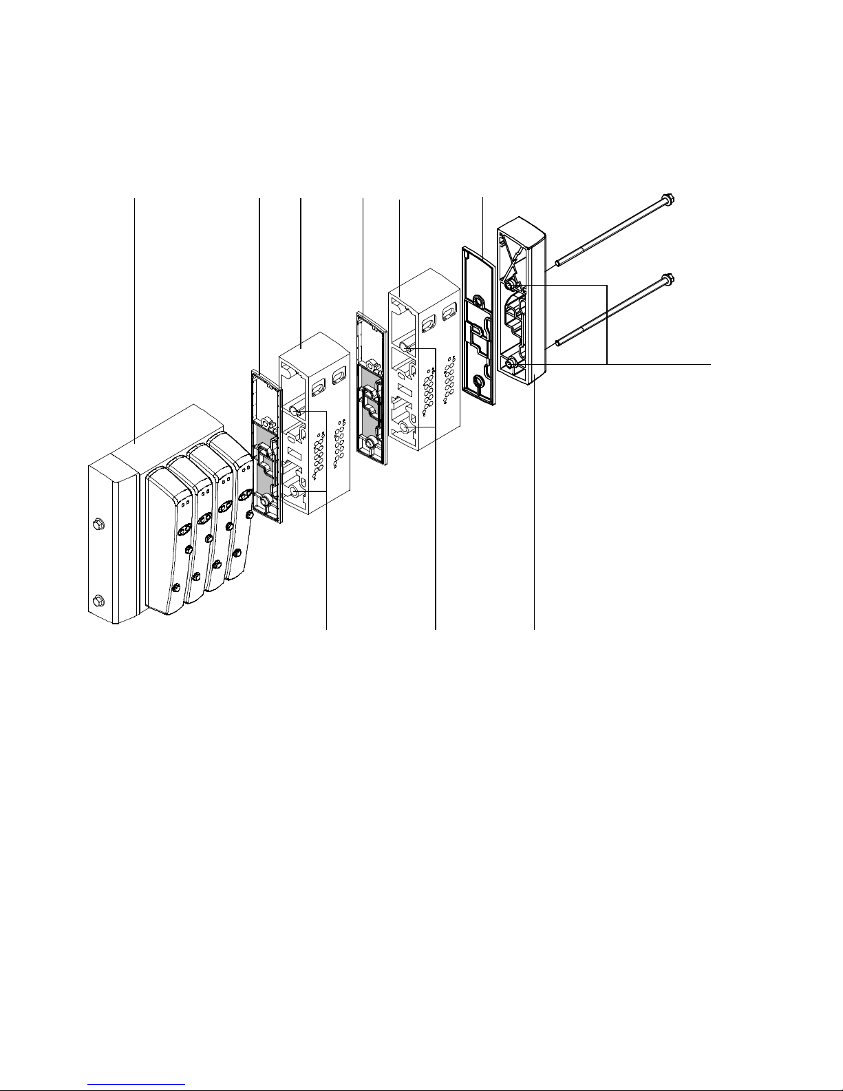
5. Cleaning, maintenance and conversion
123 45
2
6
766
Manifold block
1
2
Separator plate with channel
separation
3
Expansion block with additional supply
(first expansion block)
Fig. 5/4: Example: Fitting the separator plates on the CDVI with 3 pressure zones
4
Standard expansion block
(second expansion block)
5
Separator plate without channel
separation
6
Guide sleeves
7
Right-hand end plate
5-20
Festo P.BE-CDVI-E N en 1202e
Page 95

5. Cleaning, maintenance and conversion
5.5.4 End plates
Fitting/removing the left-hand end plates
CDVI with MP connection
The CDVI is supplied with power via the electric multi-pin plug
connection. This connection is situated in the left-hand end
plate. Remove the end plate to detach the multi-pin plug from
the CDVI.
Disassembly
1. Please observe the general preventive action
(see section 5.2)
2. Release the left-hand end plate on the CDVI by
unscrewing by one turn the two M5 mounting screws
on the left-hand end plate (see Fig. 5/5).
3. Then unscrew and remove the M5 screws from the
manifold block.
4. Disconnect the multi-pin plug from the CDVI by carefully
pulling the end plate off the manifold block.
Festo P.BE-CDVI-EN en 1202e
5-21
Page 96
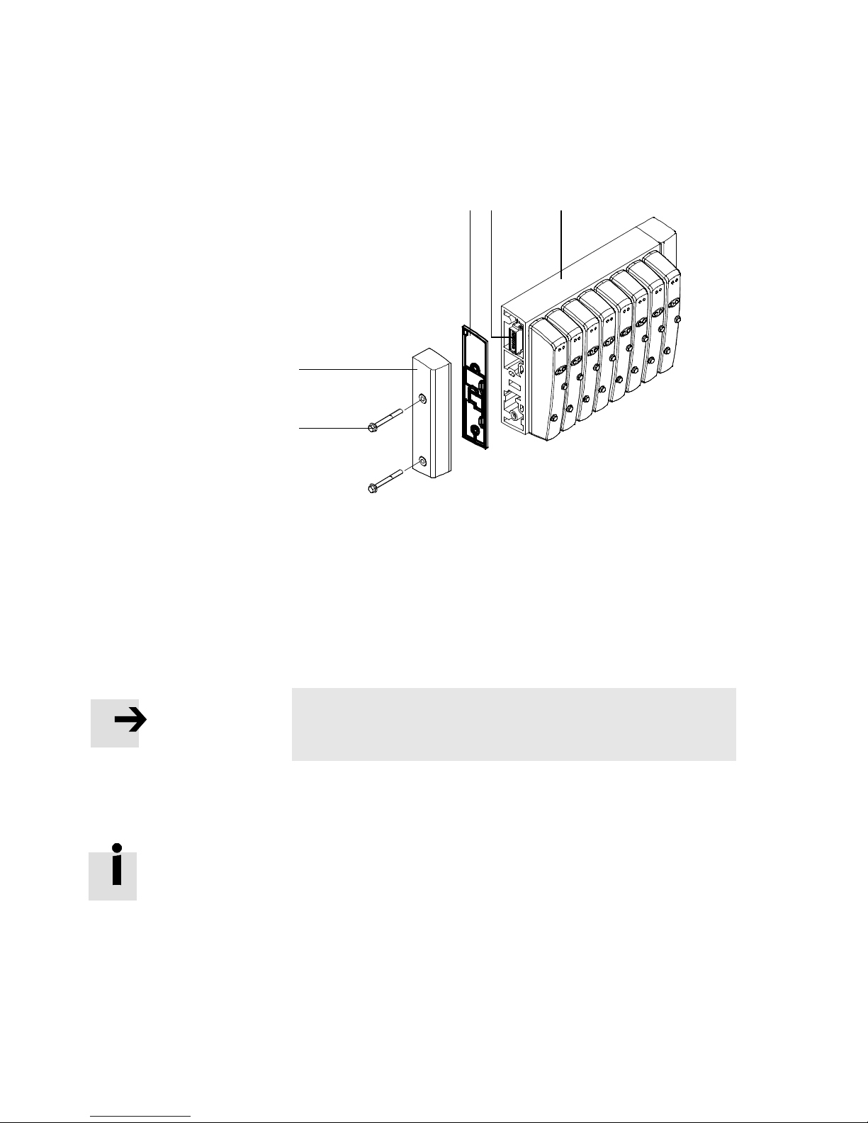
5. Cleaning, maintenance and conversion
1
M5 mounting
screws 3 ... 4 Nm
2
Left-hand end
plate
3
Seal
(separator plate
without channel
separation)
2
3
45
4
Multi-pin socket
5
Manifold block
Fig. 5/5: Fitting/removing the left-hand end plate on the CDVI with electric multi-pin
plug connection
1
Installation
1. Place the seal (separator plate without channel separation)
onto the guide sleeves of the left-hand end plate.
Note
– Make sure that the seal is seated correctly, see Fig. 5/5.
2. First align the end plate so that the multi-pin plug grips
into the multi-pin socket.
5-22
T o facilitate fitting, the multi-pin plug projects a little over the
left-hand end plate.
3. Press the left-hand end plate onto the manifold block.
4. Tighten the left-hand end plate at first by hand, so that
the seal lies evenly on the manifold block and on the end
plate.
5. Tighten the screws with 3.5 Nm (+0.5 Nm).
Festo P.BE-CDVI-E N en 1202e
Page 97
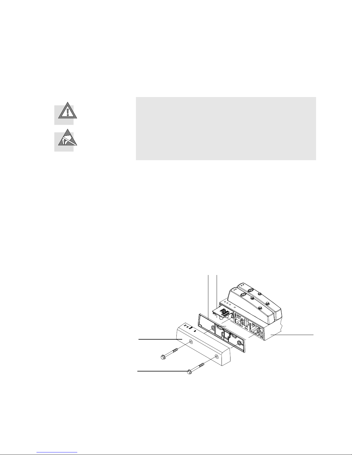
5. Cleaning, maintenance and conversion
CDVI with DI connection
Caution
The valve terminal contains electrostatically sensitive
components.
– Do not touch the electrical contacts of the components.
– Observe the handling specifications for electrostatically
sensitive devices.
Disassembly
1
M5 mounting
screws 3 ... 4 Nm
2
Left-hand end
plate
3
Separator plate
without channel
separation
4
Printed circuit
board
5
Manifold block
1. Please observe the general preventive action
(see section 5.2)
2. Release the left-hand end plate on the CDVI by
unscrewing by one turn the two M5 mounting screws
on the left-hand end plate (see Fig. 5/6).
3. Then unscrew and remove completely the M5 screws
from the manifold block and the left-hand end plates.
3
4
2
1
5
Fig. 5/6: Fitting/removing the left-hand end plate on the CDVI with fieldbus direct
connection
Festo P.BE-CDVI-EN en 1202e
5-23
Page 98

5. Cleaning, maintenance and conversion
Installation
1. Place the seal (separator plate without channel separation)
onto the guide sleeves of the left-hand end plate.
Note
– Make sure that the separator plate is seated correctly,
see Fig. 5/6.
2. Then place the left-hand end plate on the manifold block.
3. Tighten the end plate at first by hand, so that the separator plate lies evenly on the manifold block and on the
end plate.
4. Tighten the screws with 3.5 Nm (+0.5 Nm).
Fitting/removing the right-hand end plate
Disassembly
1. Release the right-hand end plate of the CDVI by loosening
thetwoM5screwsintheendplatebyoneturn.
2. Then unscrew and remove the M5 screws from the manifold block.
3. Remove the end plate from the manifold block of the
CDVI.
5-24
Festo P.BE-CDVI-E N en 1202e
Page 99
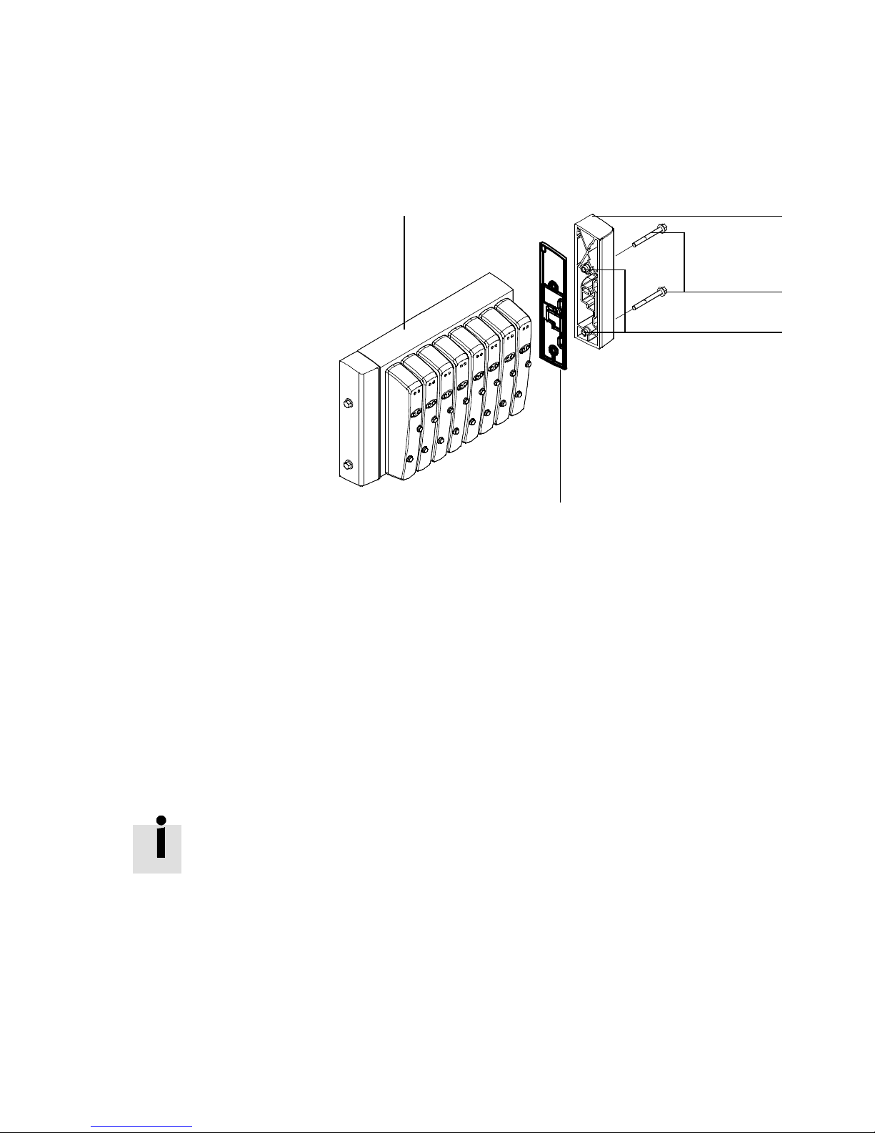
5. Cleaning, maintenance and conversion
1
Manifold block
2
End plate
3
M5 mounting
screws
4
Guide sleeves
5
Separator plate
without channel
separation
1
2
3
4
Fig. 5/7: Dismantling the right-hand end plate
Installation
1. Place the separator plate without channel separation on
the guide sleeves of the end plate. Place the end plate on
the manifold block or expansion block. Make sure that
the separator plate(s) is/are seated correctly between
the components. In this way you can ensure that
the requirements of the protection classes (see
Appendix A “Technical data”) are fulfilled.
If you have fitted the CDVI with expansion blocks at a later
stage:
– From the M5 screws supplied, use those of suitable lengt h
for fastening the right-hand end plate.
5
Festo P.BE-CDVI-EN en 1202e
2. Place the M5 screws in the right-hand end plate.
3. Tighten the end plate at first by hand, so that the separator
plate lies evenly on the manifold block and on the end plate.
4. Tighten the screws with 3.5 Nm (+0.5 Nm).
5-25
Page 100

5. Cleaning, maintenance and conversion
5-26
Festo P.BE-CDVI-E N en 1202e
 Loading...