

Page 1
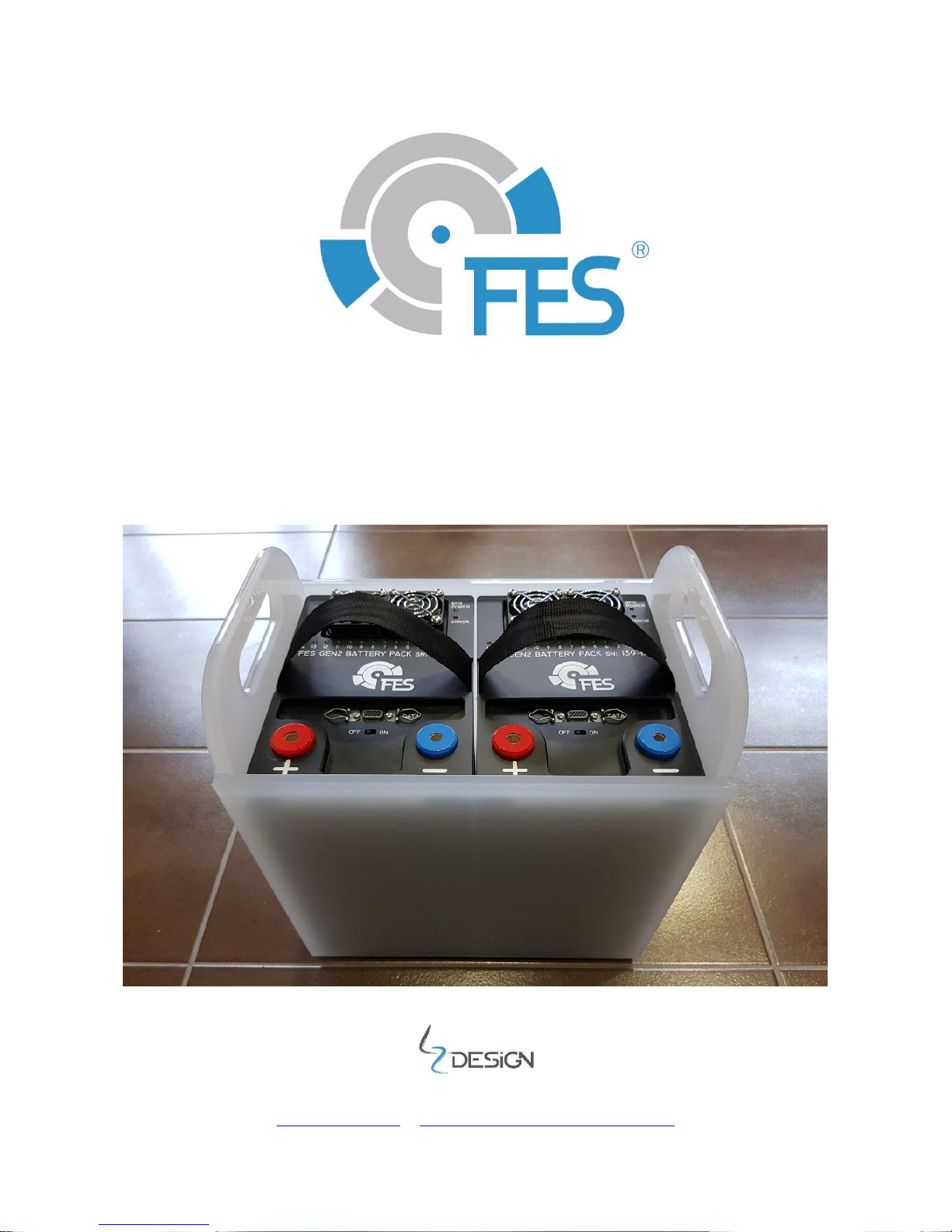
FES BATTERY PACK GEN2 manual
With integrated BMS (Battery Management System)
Version 1.18
Type: FES GEN2 14S
LZ design d.o.o., • Brod 3D, 1370 Logatec, Slovenia • tel +386 59 948 898
[email protected] • www.front-electric-sustainer.com
Page 2

FES BATTERY PACK GEN2 Version 1.18 September 2017
Page 2 of 25
Table of content
1. Important notices ..................................................................................................... 3
1.1 Limited Warranty ................................................................................................. 3
2. General info ............................................................................................................. 4
2.1 Technical data ..................................................................................................... 4
2.2 Drawing .............................................................................................................. 5
2.3 General layout of the pack.................................................................................... 6
2.4 Internal BMS ....................................................................................................... 6
3. Battery pack Chargers .............................................................................................. 8
3.1 Available chargers ................................................................................................ 8
3.2 Charger to Battery pack connection and charging ................................................ 10
3.3 BMS Control software ......................................................................................... 13
4. Before flight ........................................................................................................... 14
4.1 Installation of Battery packs into sailplane ........................................................... 14
4.2 Ground test before each flight ............................................................................ 15
5. After landing .......................................................................................................... 17
5.1 Taking Battery packs out of sailplane .................................................................. 17
6. Maintenance .......................................................................................................... 18
6.1 BMS firmware upgrade ....................................................................................... 19
7. Storage .................................................................................................................. 22
8. Transport ............................................................................................................... 20
8.1 In automobile .................................................................................................... 20
8.2 In glider trailer .................................................................................................. 21
8.3 Ship transport.................................................................................................... 21
9. Used packs ............................................................................................................ 25
10. Revision history .................................................................................................... 25
Page 3

FES BATTERY PACK GEN2 Version 1.18 September 2017
Page 3 of 25
1. Important notices
It is important to read this manual carefully before using the FES battery pack! It
contains important information about your FES system, having a vital importance to the
flight safety. If you need more information please contact the FES manufacturer LZ
design.
Information in this document is subject to change without notice. LZ design reserves
the right to change or improve their products and to make changes in the content of this
material without obligation to notify any person or organization of such changes or
improvements.
A Yellow triangle is shown for parts of the manual which should be read
carefully and are important
Notes with a red triangle describe procedures that are critical and may result
in reduced flight safety or may lead to critical situation
A bulb icon is shown when a useful hint is provided to the reader
1.1 Limited Warranty
This product is warranted to be free from defects in materials or workmanship for
one year from the date of purchase. Within this period, LZ design will, at its sole option,
repair or replace any components that fail in normal use. Such repairs or
replacement will be made at no charge to the customer for parts and labour, the customer
shall be responsible for any transportation cost. This warranty does not cover failures due
to abuse, misuse, accident, or unauthorised alterations or repairs.
THE WARRANTIES AND REMEDIES CONTAINED HEREIN ARE EXCLUSIVE AND IN
LIEU OF ALL OTHER WARRANTIES EXPRESSED OR IMPLIED OR STATUTORY, INCLUDING
ANY LIABILITY ARISING UNDER ANY WARRANTY OF MERCHANTABILITY OR FITNESS
FOR A PARTICULAR PURPOSE, STATUTORY OR OTHERWISE. THIS WARRANTY GIVES
YOU SPECIFIC LEGAL RIGHTS, WHICH MAY VARY FROM STATE TO STATE.
IN NO EVENT SHALL LZ DESIGN BE LIABLE FOR ANY INCIDENTAL, SPECIAL, INDIRECT
OR CONSEQUENTIAL DAMAGES, WHETHER RESULTING FROM THE USE, MISUSE, OR
INABILITY TO USE THIS PRODUCT OR FROM DEFECTS IN THE PRODUCT. Some states
do not allow the exclusion of incidental or consequential damages, so the above limitations
may not apply to you. LZ design retains the exclusive right to repair or replace the unit or
software, or to offer a full refund of the purchase price, at its sole discretion. SUCH
REMEDY SHALL BE YOUR SOLE AND EXCLUSIVE REMEDY FOR ANY BREACH OF
WARRANTY.
To obtain warranty service, contact your local LZ design dealer or contact LZ design
directly.
June 2013 © 2013 LZ design. All rights reserved
Page 4

FES BATTERY PACK GEN2 Version 1.18 September 2017
Page 4 of 25
2. General info
This is standard FES battery pack which is built from 14 Lipo cells which are all wired
in serial. For FES application, always a pair of such battery packs is required. One pack is
marked as A and second pack as B!
We are using high power SLPB (Superior Lithium Polymer Battery) type of cells,
produced by global leader of Lithium polymer battery industry - Kokam Co.
Each Battery pack is equipped with internal BMS (Battery Management System)
circuit board which is fixed above the cells, and is equipped with 16 LEDs to monitor its
operation.
For + and - terminals we chose to use Amphenol Radsok hyperbolic high-power
contact technology. High current female contacts are hidden inside of the pack.
To avoid possible wrong connections there is 8mm contact for – pole and 10,3mm
contact for + pole.
2.1 Technical data:
Battery pack type
FES GEN2 14S
Weight of single battery pack
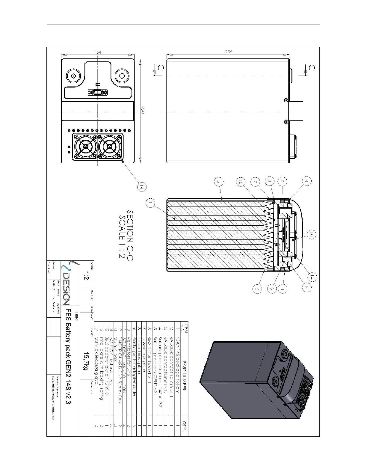
15,7 kg
Box dimensions (WxLxH), without terminals and ventilators
154 x 220 x 257mm
Cells producer
Kokam, South Korea
Cells type
SLPB100216216H
Average capacity of each cell
41 Ah
Number of cells
14
Energy storage capacity
2,1 kWh
Maximum total voltage
58,3 V
Minimum total voltage
42 V
Maximum current
250A
Max balancing current per cell
1A
Internal BMS type
FES-BMS-9R
Standard 600W small charger
KOP602 BMS
Optional 1200W biger charger
KOP1001 BMS
Optional 2000W fast charger
Robust R2300 BMS
Page 5
FES BATTERY PACK GEN2 Version 1.18 September 2017
Page 5 of 25
2.2 Drawing
Page 6
FES BATTERY PACK GEN2 Version 1.18 September 2017
Page 6 of 25
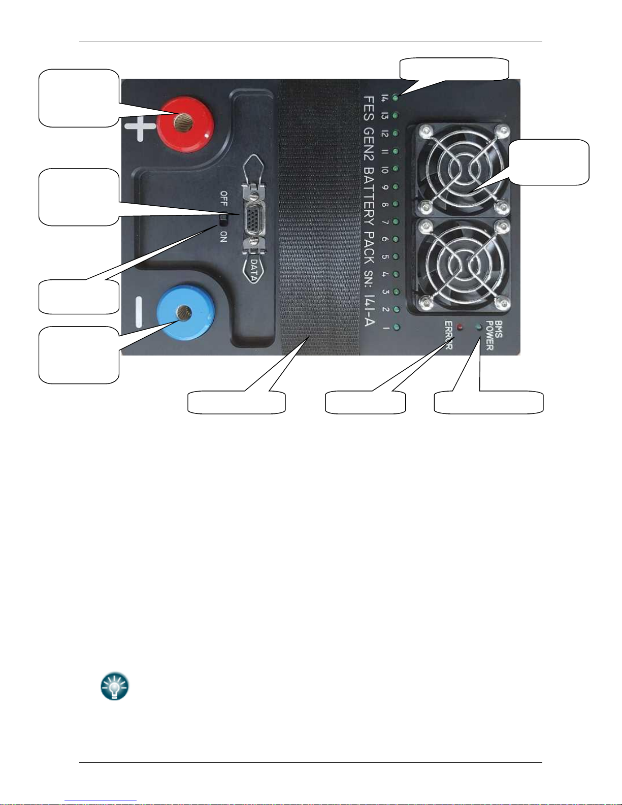
2.3 General layout of the pack:
Top view of FES GEN 2 battery pack
2.4 Internal BMS
Your battery packs are equipped with internal BMS (battery management system)
electronic circuit. What is a BMS?
During charging and discharging LiPo battery cells differ in voltage levels, due to
slightly different capacity of cells. Cells with lower capacity charge and discharge faster
than cells with higher capacity. LiPo cells have nearly linear voltage to capacity
dependence. BMS controls the voltage of each cell in the battery pack. Cells which have
higher voltage than the others, are discharged through resistor inside of BMS – the energy
dissipates through heating of upper plate of pack which is milled from Aluminum. To
improve dissipation of the heat there are two small ventilators on top of the upper plate
which starts when upper plate reach preset temperature.
Balancing of each cell is indicated by green light emitting diode (LED).
Internal BMS in battery pack balance cells only in the presence of a
CHARGER and above pre-set balancing voltage.
Plus pole
RADSOK
terminal (fi
10.3mm)
Minus pole
RADSOK
terminal (fi
8,0mm)
DATA cable
connector,
with spring
locks
BMS ON-OFF
switch
Balancing LEDs 1-14
»BMS POWER« LED
»ERROR« LED
Strap for carrying
BMS cooling
plate
ventilators
Page 7

FES BATTERY PACK GEN2 Version 1.18 September 2017
Page 7 of 25
BMS DATA AND INITIAL SETTINGS
Parameter
Value
Unit
Single cell end of charge voltage*
4.16
V
Single cell charging hysteresis*
0.1
V
Single cell balance start voltage*
4.1
V
Maximum charging current
9,18,35
A
Single cell balance 100 %*
4.16
V
Balance resistor
3.9
Ω
Single cell under-voltage protection*
3.24
V
Single cell over-voltage protection*
4.20
V
Single cell over and under-voltage
protection hysteresis
0.01
V
BMS over-temperature protection*
45
°C
BMS over-temperature hysteresis
10
°C
*Initial settings may be changed with BMS Control software.
Page 8
FES BATTERY PACK GEN2 Version 1.18 September 2017
Page 8 of 25
3. Battery pack Chargers
For charging FES battery pack, we provide a special CHARGERS as part of complete
FES system.
If you are ordering only Battery packs, then you need to specify if you want to
order also charger and which type!
3.1 Available chargers
Three types of chargers are available for charging FES GEN2 battery packs:
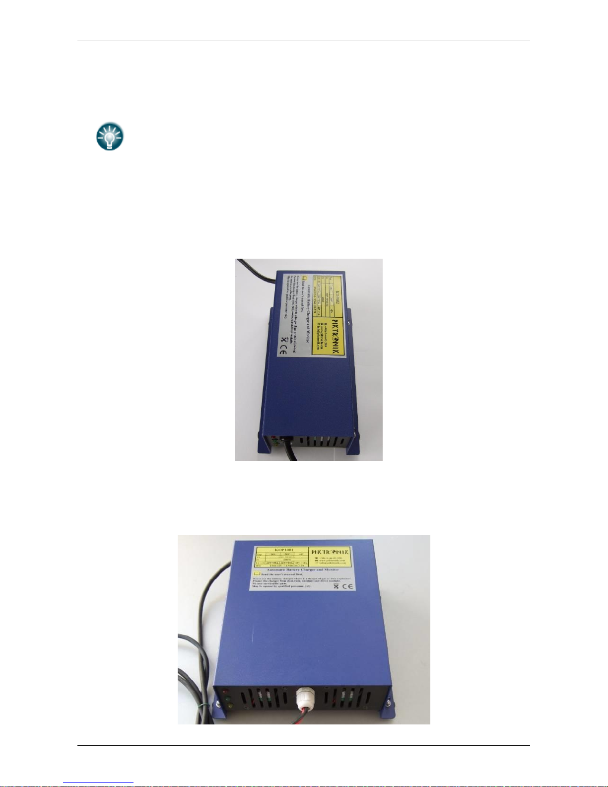
1. KOP602 BMS version (600 W, 2.2kg), maximum charging current 9A.
This is standard small FES charger. We provide two such chargers so that both FES GEN2
battery packs can be charged at the same time.
KOP 602 BMS Charger
2. KOP1001 BMS version (1200 W, 3.9kg), with maximum charging current 18A.
This is optional FES charger.
KOP1001 BMS Charger
Page 9
FES BATTERY PACK GEN2 Version 1.18 September 2017
Page 9 of 25
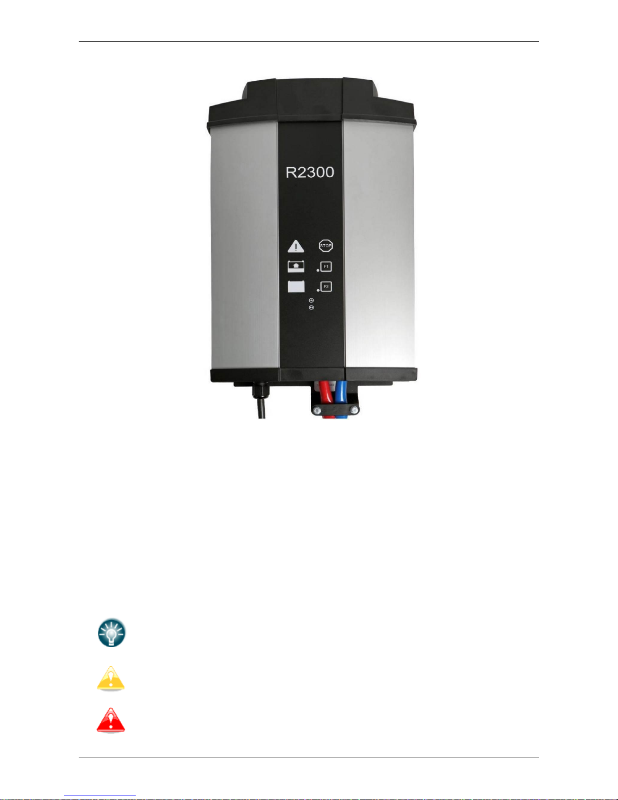
3. Robust R2300 BMS version (2000W, 6.1kg), with maximum charging current 35A.
This is optional FES charger.
Robust R2300 charger
KOP602, KOP1001 and R2300 are modern programable fully automatic battery
chargers, which works only in combination with BMS which is inside of the battery pack.
We program each charger with suitable settings for FES GEN2 14S.
Those chargers stores data about charging times and Ah charged. This data may be
accessed for further analysis by manufacturer.
Required input voltage is 230V~ 50/60 Hz. Unfortunately is not available 110V
version of charger. If your country is using 110V grid, then you should use suitable
voltage step up transformer.
Before using the charger, check that the fuse on the grid is suitable. For
1200W charger it should be minimum 10A fuse. Always try to connect
charger directly to inlet, without extension cables and splitters if possible.
Each Battery pack must be charged separately.
If you ordered another pair of Battery packs, make sure that you
do not mix packs between the sets. The same two packs of one set
(first marked as A, second marked as B) must be always used in
pair!
Page 10
FES BATTERY PACK GEN2 Version 1.18 September 2017
Page 10 of 25
3.2 Charger to Battery pack connection and charging
Place Charger on a safe, secure position. Keep away from dust, direct sunlight,
fire, smoke, childrens and any unatendent person!
Before charging, physical condition inspection of the battery packs should be
done. Any sign of mechanical damage, such a puncture, dents, scratches, must
be evaluated and reported to manufacturer before charging.
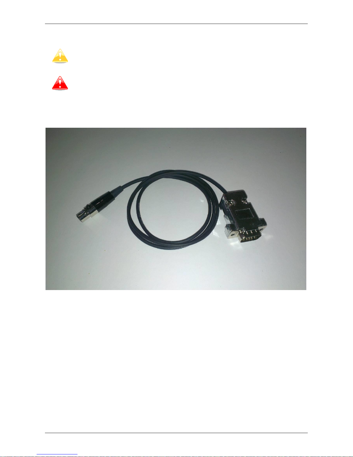
1. Connect RED + and BLACK - cables from charger to first battery pack.
2. Connect charger and Battery pack with BMS-Charger signal cable.
BMS-Charger signal cable
3. Plug in Charger to (220V AC, 50-60hz only) outlet
4. Turn on BMS switch on top of the Battery pack cover
Immediately after BMS is switched ON, the BMS starts test procedure - with check
of all 14 cells, one by one. Red »Error LED« turns ON during system's test
procedure, and switch OFF again when test is completed without error.
5. When test procedure is completed also a green »Power LED« starts blinking, which
is clear sign that BMS starts working in normal mode. At the same time, BMS sends
signal to the CHARGER in order to start charging. Orange LED on front panel of the
CHARGER starts burning, which indicates charging. It is also possible to hear the
sound of contactor "click" inside of the CHARGER. Charging current rises slowly to
the final value of 9 A (or 18A at 1200W version), and after some time, cooling fans
in CHARGER starts.
Page 11
FES BATTERY PACK GEN2 Version 1.18 September 2017
Page 11 of 25
6. In normal mode green »BMS Power« LED of BMS is starting flashing. This means
that the BMS is turned ON, but not necessary balancing. Normally balancing starts
when one cell reaches pre-set value, usually 4,1V (could be changed by BMS
Control Software). If any of 14 green LED cell balancing indicators is ON, it means
that this cell has slightly higher voltage compared to the lowest one.
Possible scenarios:
1. If one or more cells have higher voltage levels that the others, it will
discharge them, the BMS temperature rise will be minimal.
2. If only one cell has lower voltage level than all the others, all higher cells
need to be balanced. This leads to higher BMS temperature, even if voltage
difference is only 0.010 V (10mV).
If upper BMS cooling plate of battery pack reach 50 °C, then cooling
ventilators starts working.
Somethimes in hot conditions, temperature of BMS cooling plate
could still rise despite of working ventilators. In such case when
temperature of cooling plate would reach 55 °C, CHARGER would
be switched off automatically. When temperature drops to 45 °C,
charger would start charging again.
7. Red »Error LED« is ON only during the initial test procedure. After the test is
finished it turns OFF. Some system errors are also indicated with red »Error LED«
by the number of ON blinks, followed by a longer OFF state. Number of blinks
identifies the error:
Number of blinks
Error describtion
1
Single or multiple cell voltage is too high (4.2 V) *
2
Single or multiple cell voltage is too low (3.24 V) *
3
Cell voltages differ more than preset value (0.5 V) *
4
Cells temperature is too high (>55 C) *
5
BMS temperature is too high (>50°C) *
6
Number of cells is not set properly
7
Too low temperature for charging < -1°C
8
BMS do not recognize temperature sensor
9
Communication error
10
Measurement of cell below 0,1V or above 4,8V
13
Wrong chemistry set by BMS control software
*Initial settings may be changed with BMS Control Software.
Page 12
FES BATTERY PACK GEN2 Version 1.18 September 2017
Page 12 of 25
8. When first cell reaches 4.160V, charging current is reduced. If there is a big
difference between cells (more than 50mV) then it can take quite long until they all
reach 4,16V, as charging current is only 1A.
9. When finally, all cells reach 4.160V (+/- 2mV), then BMS send a signal to
CHARGER to stop charging. At this point Green “Power LED” stops flashing and
become continiously Green.
This is clear message that charging cycle is properly completed!
10. Switch OFF BMS on top of Battery pack. Unplug charger from outlet. Unplug
charging cables and signal cable from Battery pack.
11. Charge second Battery pack!
Both battery packs must have approximately the same cell voltage levels
(close to 4.16 V per cell), before usage. Using two packs with too much
difference in voltage levels is not allowed!
Maximum 0,4V difference between total voltages of both packs is acceptable.
If is more is not acceptable!
For instance, Pack 1: 58,24V (4.160 per cell), Pack 2: 57,82V (4,130V per
cell), this is just acceptable!
If thunderstorm is approaching, stop charging immediately and disconnect
the charger from the wall.
Page 13
FES BATTERY PACK GEN2 Version 1.18 September 2017
Page 13 of 25
3.3 FES BMS Control software
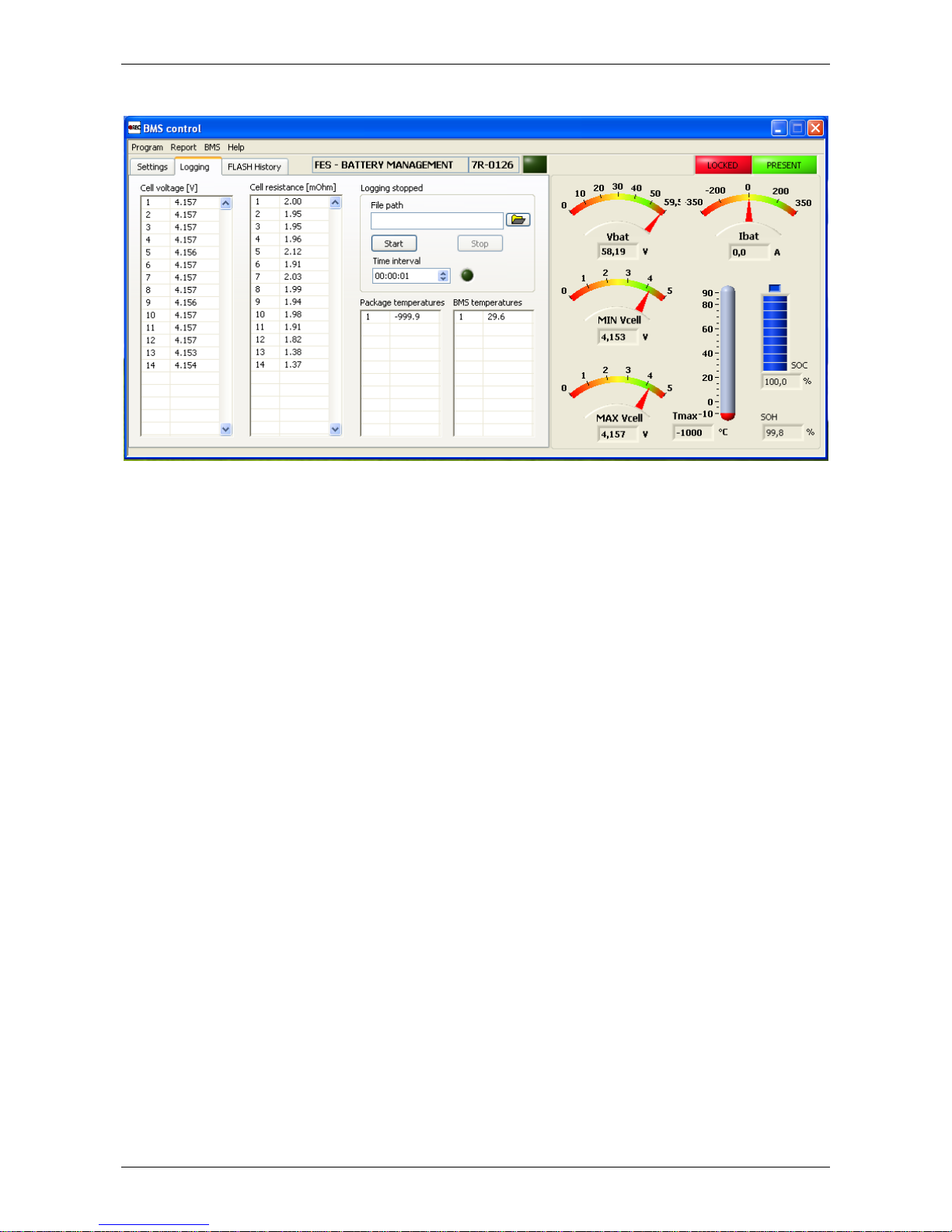
Cells voltage levels, and calculated internal resistance values on fully charged battery pack
If you want to monitor and log how voltage level of each cell in battery pack is
rising during charging, you can use dedicated BMS Control software on PC.
In case that some problems are discovered during charging, log file can be created
and later you can send it by email to FES manufacturer. It can help us to discover the
problem and find a suitable solution.
How to install and use FES BMS Control software is described step by step in
dedicated FES BMS Control manual, which can be obtained from FES dedicated website, in
download section.
Page 14
FES BATTERY PACK GEN2 Version 1.18 September 2017
Page 14 of 25
4. Before flight
Before each flight battery packs should be recharged, especially if engine was used
during previous flight, so that maximum energy is available if needed. This is very
important in cold conditions, where voltage drop under high power load could be
significant.
Both battery packs must have approximately the same cell voltage levels
(close to 4.16 V per cell), before usage. Using two packs with more than 1 V
difference in total voltage levels between packs is not allowed!
4.1 Installation of Battery packs to the sailplane
1. Open battery compartment cover
2. Check that “Power switch” is OFF
3. Check that FCU instrument and all other instruments (Flight computer, Flarm, Radio,
Transponder, PDA...) are switched OFF
4. Insert first pack into the fuselage so that terminals are facing forward and slide it back
to rear position.
5. Insert second pack into the fuselage so that terminals are facing rearward.
6. Place pair of fixation plates in the middle of rear pack, above carrying strap and
tighten fixation knob.
7. Place pair of fixation plates in the middle of front pack, above carrying strap and
tighten fixation knob.
8. Lift power cables from side support.
9. Plug in shorter cable, with 8mm pin in BLACK housing, to minus marked 8mm socket
of front battery pack.
10. Plug in longer cable with 10mm pin in RED housing, to plus marked 10mm socket of
rear battery pack.
11. Insert DATA cable connectors, to each battery pack DATA connector.
Before connection, make sure that orientation is correct. Connector should
be plugged in straight direction, otherwise pins could be damaged!
12. Turn ON “BMS switch” on each battery pack, and wait until initial check is completed
13. Close battery compartment cover.
Page 15
FES BATTERY PACK GEN2 Version 1.18 September 2017
Page 15 of 25
4.2 Ground test before each flight
It is strongly recommended to perform short ground test run before each
flight, to be sure that everything works fine.
1. Remove a tail dolly in order to achieve safe propeller clearance.
2. Open battery compartment cover.
3. Check that “Power switch” is OFF.
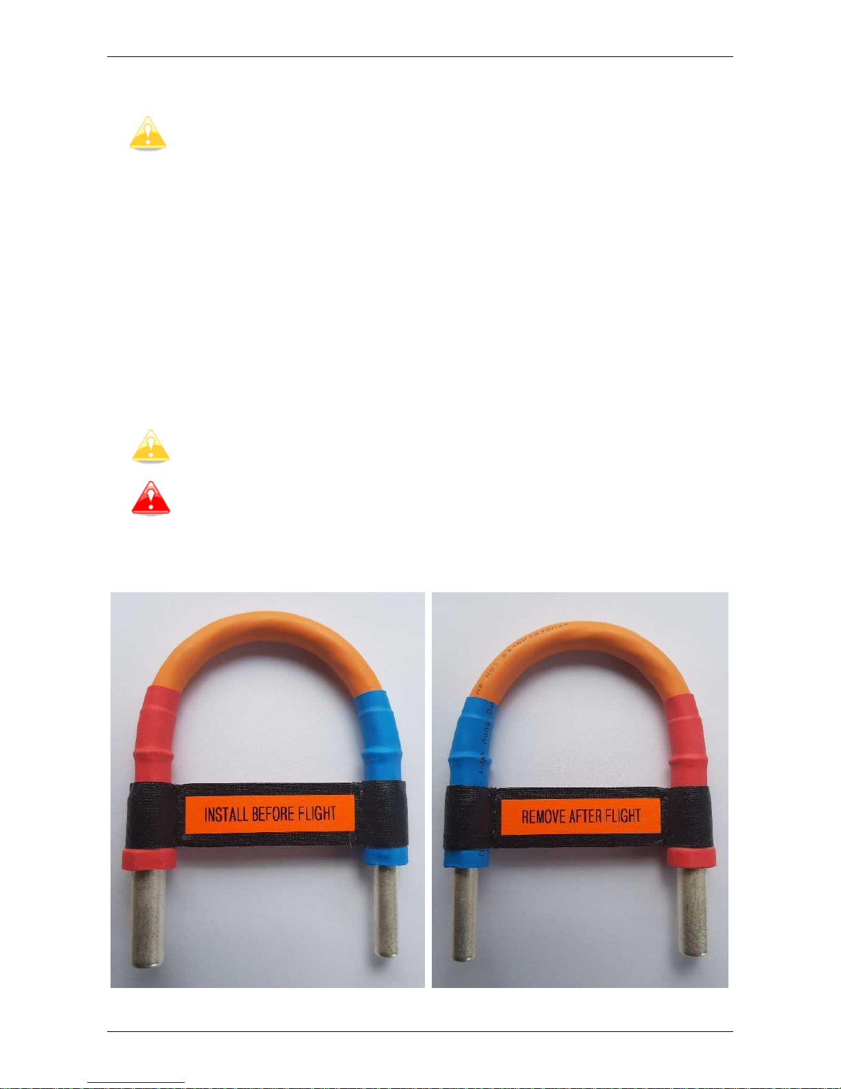
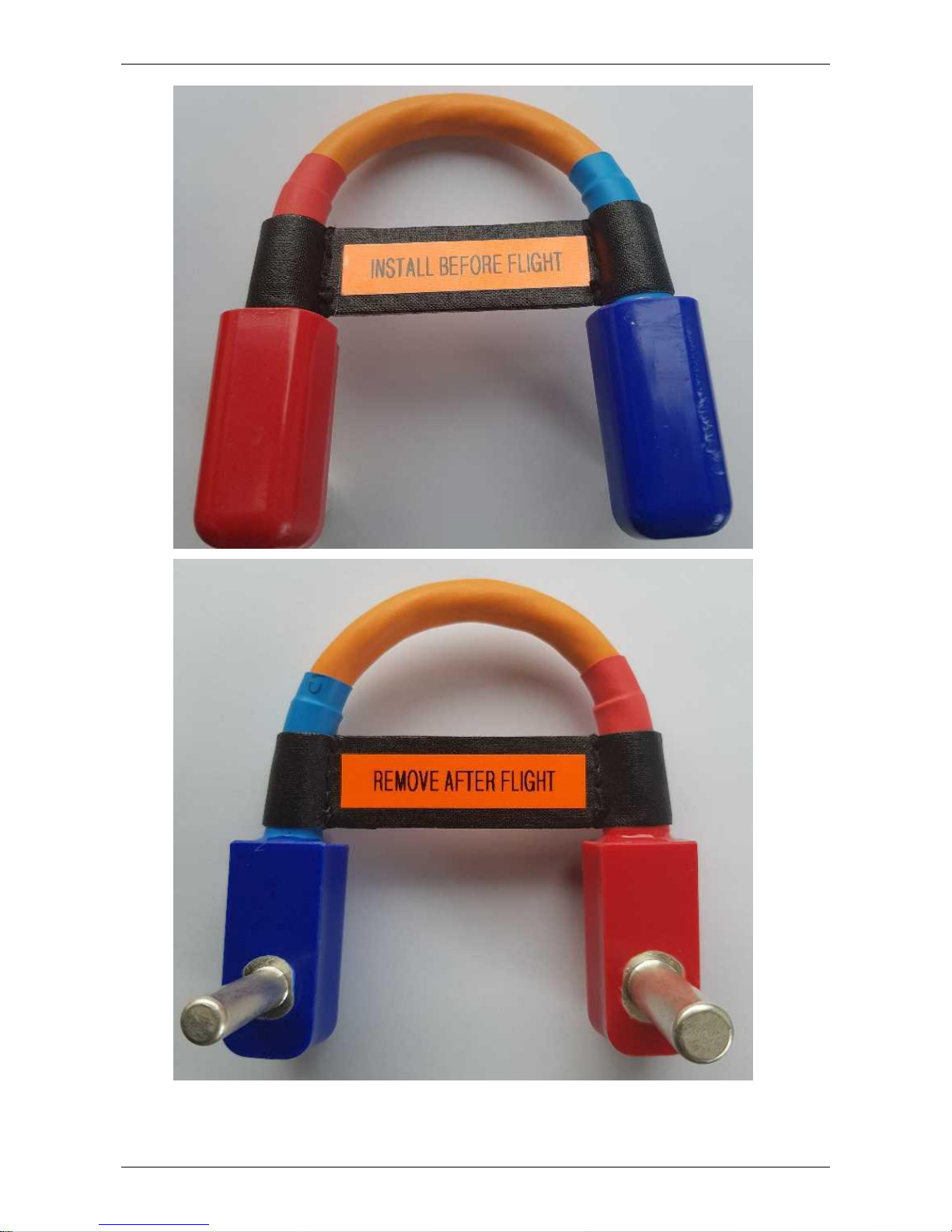
4. Insert “connecting cable” between the front pack + terminal, and rear pack –
terminal.
5. Seat into the cockpit of the glider, and close canopy.
6. Check that nobody is in line of propeller disk or in front of sailplane.
7. Switch ON FCU, and wait a few seconds until appearance of normal screen.
8. Switch ON “Power switch”.
9. Wait about 5 second, and battery capacity bottles should get back to 100%
value (this will happen only if total voltage is above 114V).
10. Gently rotate throttle knob clockwise in order to start motor. Use only small RPM, just
to check if system works normally.
New battery capacity will be stored to the FCU memory, only if
motor is started, for short time.
In case that you would like to test system at max power, somebody needs to
hold a fuselage tube down, and hold a glider.
11. Check if propeller braking and automatic positioning is working properly.
Standard type of “Connecting cable”, as used on most FES systems.
Page 16
FES BATTERY PACK GEN2 Version 1.18 September 2017
Page 16 of 25
Right angle type of “Connecting cable”, as used on LAK gliders.
Page 17

FES BATTERY PACK GEN2 Version 1.18 September 2017
Page 17 of 25
5. After landing
After landing (or if you decided not to fly) it is mandatory to unplug
“Connecting cable”, from the battery packs!
At the same time, also both BMS switch on top of battery packs,
must be switched OFF.
Only when connecting cable is unplugged, FES system is completely
shut down. Otherwise there is still consumption of about 25mA,
which could result in discharge of battery packs, below critical level
of 90V, if connecting cable is left connected for a week or two!!!
After such scenario, a new pack would be required, and they are
rather expensive!
5.1 Taking Battery packs out of sailplane
Before each flight it is recommended to have fully charged battery packs, in order
to have maximum available range if required. If battery packs were discharged during
flight, it is best to take them out of the glider, and recharge them shortly before next
flight is planned. To take out battery packs next procedure should be followed:
1. Check that “Power switch” is OFF.
2. Check that FCU instrument and all other instruments (Flight computer, Flarm, Radio,
Transponder, PDA…) are switched OFF.
3. Open battery compartment cover.
4. Pull out “Connecting cable” from terminals of battery packs.
5. Pull out both (RED + and BLACK -) power plugs from battery packs.
6. Fix both power cables to the right side of battery compartment box.
7. Remove DATA connectors, from each battery pack.
8. Fix DATA cable to the side of battery compartment box.
9. Unplug tighten battery pack fixation knobs.
10. Take all fixation plates out.
11. Firmly grip the front battery by a carrier strap.
12. Lift it out of the fuselage and put it on safe place.
13. Firmly grip the rear battery by a carrier strap and slide it forward along the bottom of
the battery compartment.
14. Lift the battery pack out of the fuselage and put it on safe place.
15. Close battery compartment cover.
Page 18

FES BATTERY PACK GEN2 Version 1.18 September 2017
Page 18 of 25
6. Maintenance
With proper and carefull use of FES battery packs, there is practically no maintence
required. FES battery packs are built from the most suitable cells available, so that they
are able to provide high power and good endurance and will serve you for many years and
charging cycles.
Unfortunately, some capacity deterioration will occur due to aging of the
cells whether the battery packs are in use or not. The useful life of a lithium
cells is based on several factors which can prevent the battery from
providing sufficient current draw due to increased internal resistance.
Suitable uses and threatment that will reduce this deterioration include:
1. During powered flight, use low power settings as much as possible and practical.
2. Do not discharge cells below 3,4V (total voltage at 95V), if is not really neccesery.
3. Store battery packs at suitable temperatures when they are not in use (review next
chapter 7. Storage)
4. Store battery packs at suitable charge levels (around 50% SOC, see next chapter 7.
Storage)
Good indication of the battery packs condition is SOH – State Of Health %
parameter, which can be read in lower right corner of BMS control software. It is
calculated from average internal resistance of the cells, measured during charging.
With poor threatment of the battery packs, their cells internal resistance will be
rising faster, and so calculated SOH % level will become lower. When it will be as low as
50%, it would be time to think about replacement of the battery packs (at least the cells,
BMS electronic could be reused).
Poor condition of the cells can be recognizable also during powered flight:
-much deeper voltage drops at max power settings
-much reduced maximum achievable power (with fully charged packs)
-much reduced usable capacity – altitude gain and range of level flight
-temperature rise gradient of the battery pack will become much faster
We suggest replacing FES battery packs, when maximum available
range of level flight (to reach 90V or 55°C, whatever first), is
reduced to one third of the range experienced when they were
new. Probbably there would be not much sense to utilize them
further on in such conditions.
Please handle FES battery packs very carefully, in order to avoid any mechanical
damage of housing. Only if battery packs are free of any damages it is allowed to charge
them and then put them into the glider. So they must be always visually inpected before
each charging and before installation to the glider. This is even more important when
glider is used by a syndicate of pilots or in aeroclubs.
If housing is found to be damaged, somethimes also cells inside might be
damaged, which could be dangerous. In such case please contact manufacturer, for
evaluation of damage and further steps.
Page 19
FES BATTERY PACK GEN2 Version 1.18 September 2017
Page 19 of 25
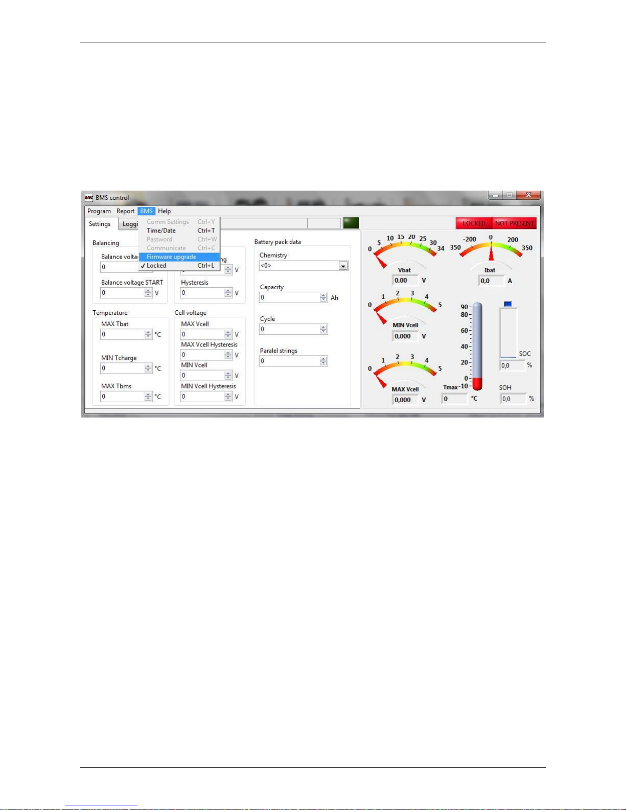
6.1 BMS firmware upgrade
From time to time there might be available new improved version of BMS firmware.
It is easy to perform upgrade, by using provided BMS-Charger-PC cable, and BMS Control
software which is available to download from FES dedicated website.
If there is any strange behaviour of BMS, upgrade usually resolve the problem.
To perform upgrade is it required suitable .bin file, which we can send it to
customer by email. Please save it to chosen location on PC disk drive.
Connect BMS-Charger-PC cable to BMS and to USB port of PC. Run BMS Control
Software, cancel any initial error messages which might appear (note that for firmware
upgrade green PRESENT indication is not required). From upper menu choose BMS, then
Firmware upgrade and browse for .bin file where you save it on PC (named like: BMS_9R-
2.22.bin). Switch ON, the BMS switch on top of the battery pack. Wait until programming
will reach 100% in progress window. BMS will restart itself and start working normally!
Page 20
FES BATTERY PACK GEN2 Version 1.18 September 2017
Page 20 of 25
7. Transport
7.1 Car transport
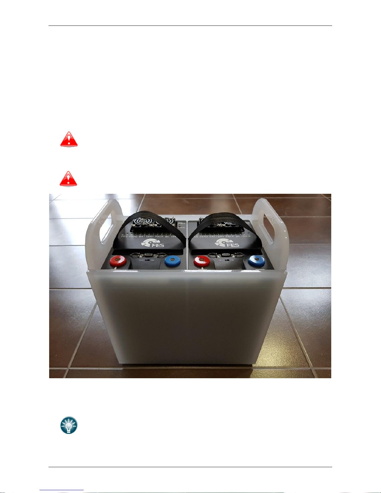
Most of the mechanical damages on the housing, which we recently recognized on
alerting number of FES battery packs, seems to be result of unsuitable way of
transportation in the cars. We decided that it is mandatory to use FES transportation
box. For safety reasons, box must be placed into the luggage compartment, pushed
forward up to the front wall. Transportation box should be additionaly secured, so that it
can not move backward during acceleration, or forward at braking.
For safety reasons (and common sense) it is not allowed to
transport battery packs in the car cockpit, for instance behind
drivers or co-drivers seat, or infront of the co-driver seat, as in
case of accident it could be very dangerous!
Do not leave battery packs in the parked car under sun in hot
summer, as they might be exposed to high temperatures.
FES transportation box (white plexiglas)
For all FES sailplanes delivered after 17. October 2017, FES transportation
box is part of standard FES equipment.
If your glider was delivered before this date you probably did not receive
transportation box, unless you order it as part of optional equipment. In
such case please contact us to order FES transportation box, as it is
mandatory to use it, for safety reasons.
Page 21

FES BATTERY PACK GEN2 Version 1.18 September 2017
Page 21 of 25
7.2 In glider trailer
It is not allowed to transport battery packs in the front area of
glider trailer.
For transportation in glider trailer, FES battery packs must be placed in the battery
compartment of the glider, and they must be properly fixed as during flight.
“Connecting cable” must be always removed when glider is stored
in trailer.
7.3 Ship transport
When your glider is transported in container (to USA, Namibia, South Africa,
Australia…), with or without its trailer, we suggest placing FES battery packs into battery
compartment of the glider, as there are properly fixed as during flight. Another possibility
is to place battery packs into FES stainless steel storage boxes, and fix them to the corner
of the container.
It is recommended that gliders are packed into bright coloured containers, where
internal temperature of the container on hot days at the sea might be lower.
Page 22
FES BATTERY PACK GEN2 Version 1.18 September 2017
Page 22 of 25
8. Storage
When you stop flying for longer time, for instance during winter time, it is
mandatory to discharge FES battery packs to 50% of charge. This is to middle voltage,
3,7V per cell (this is about 52V per pack, or 104V indicated on FCU instrument, when
motor is stopped).
-you can discharge them during last flight at the end of season, or
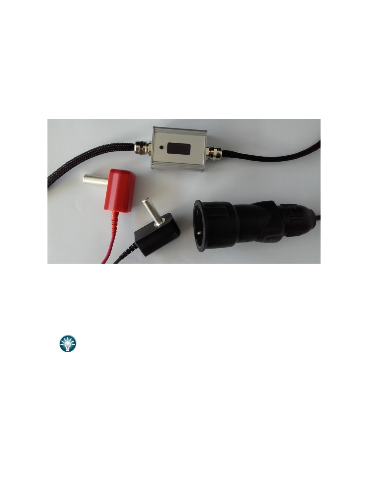
-you can use FES discharging assistant device (more info about this optional
equipment you can find on our FES website)
FES discharging assistant
The most important environmental factor for slowing aging is the temperature at
which battery packs are stored. Store battery packs between 10°C to 20°C, at normal
humidity conditions. Do not store batteries at high temperatures or below freezing
temperatures or in very humid environment (like in poor all metal glider trailer).
Always try to avoid having packs exposed to high temperature, as high
temperature is decreasing life of cells significantly.
Page 23
FES BATTERY PACK GEN2 Version 1.18 September 2017
Page 23 of 25
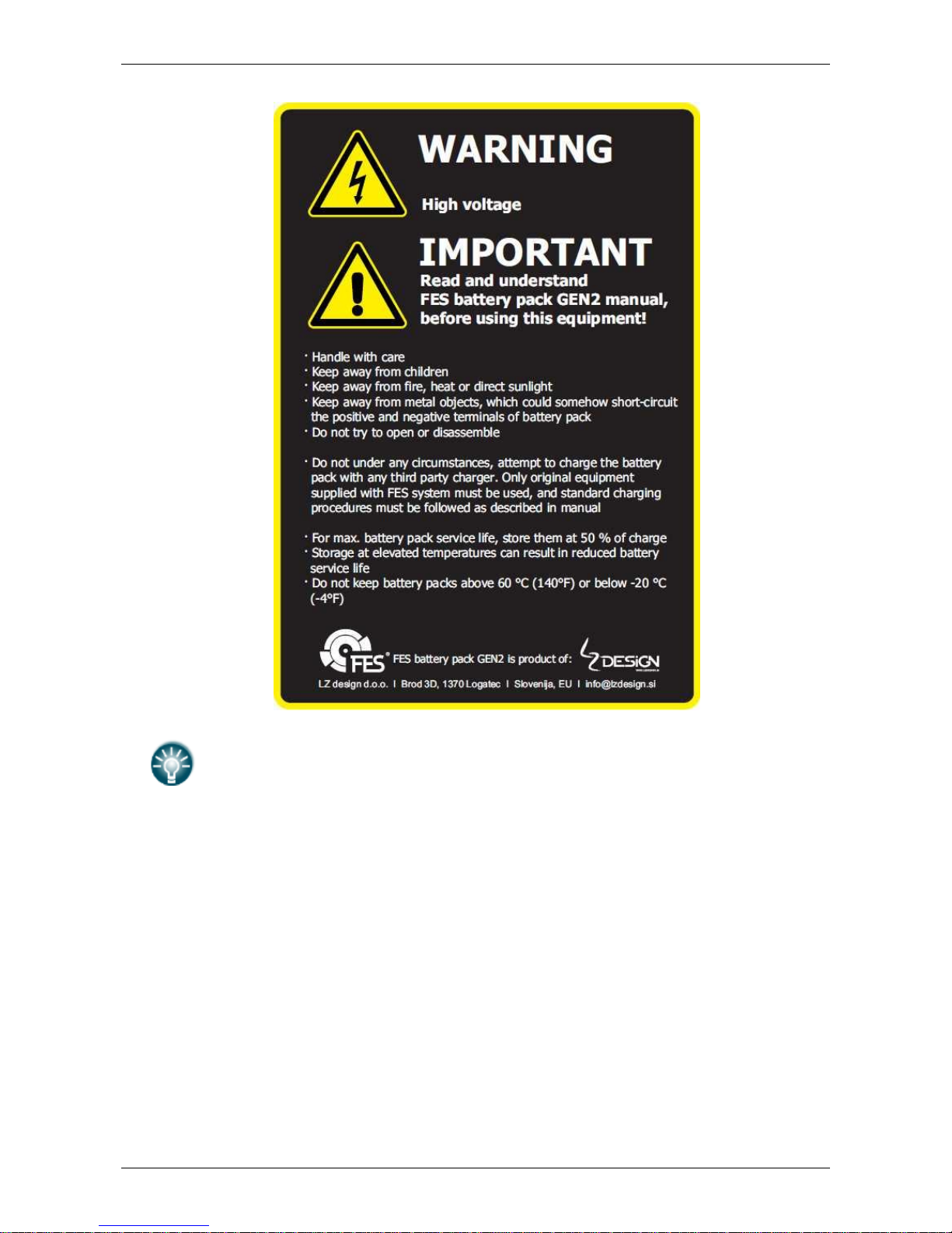
Warning sticker as above, with some basic information regarding storage, is
located on front vertical wall of each FES battery pack!
Page 24
FES BATTERY PACK GEN2 Version 1.18 September 2017
Page 24 of 25
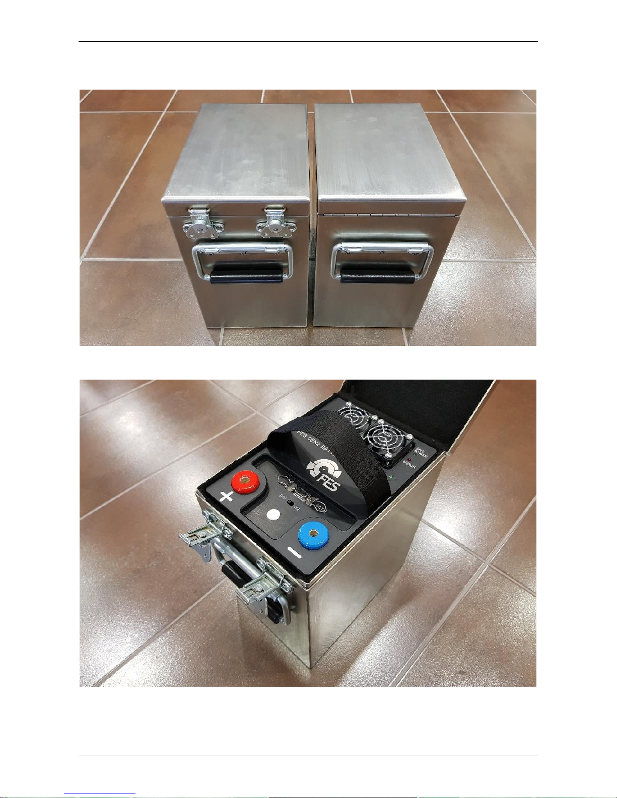
For storage, (and also transportation or charging) we developed FES stainless steel
storage box, which is optionaly available.
Pair of FES stainless steel storage boxes
FES GEN2 Battery pack placed into FES storage box
Page 25

FES BATTERY PACK GEN2 Version 1.18 September 2017
Page 25 of 25
9. Used packs
Check document “Handling instruction for used battery”.
10. Revision history
February 2013
Initial release of manual, Version 1.0
March 2013
Minor updates, Version 1.1
June 2013
Updates of error codes, Version 1.11
December 2013
New photo of BMS-PC cable, Version 1.12
August 2014
Some info about good practice added, Version 1.13
March 2015
Update with drawing, transportation box and sticker, Version 1.14
July 2015
Minor updates, Version 1.15
October 2016
New maintenance section, Version 1.16
November 2016
Additional info about DATA connector, Version 1.17
September 2017
Minor correction about BMS switching OFF, and new info about
powerfull R2300 charger, storage and transport section updated,
Version 1.18
 Loading...