

Page 1

INSTALLATION MANUAL
FERRUPS
0800-2000 - 0800-7500
Page 2

FERRUPS
®
Installation Manual
0800-2000 through 0800-7500
2 kVA-7.5 kVA 50 and 60 Hz
Uninterruptible Power Systems
IMPORTANT SAFETY INSTRUCTIONS.
SAVE THESE INSTRUCTIONS.
This manual contains important instructions for your UPS.
LTM-1320E
© 1998-1999 Best Power. All rights reserved.
Page 3

Introduction
This manual is for the types of models listed below.
• All models that do not have a power cord and input plug or that do not have output receptacles. A qualified
electrician must install the AC wiring for these models and connect your protected equipment. Sections
200, 300, and 500 of this manual describe the AC wiring and phase check.
• All models that have a separate battery cabinet. Section 300 describes battery installation.
The installation and use of this product must comply with all national, federal, state, municipal, or local codes
that apply. If you need help, please call the nearest Best Power office.
Best Power
P.O. Box 280
Necedah, WI 54646 U.S.A.
Telephone: 1-608-565-7200
Toll-Free: 1-800-356-5794 (U.S.A. and Canada)
FAX: 1-608-565-2221
International FAX: 1-608-565-7675
Worldwide Service
P.O. Box 11
Necedah, WI 54646 U.S.A.
Telephone: 1-608-565-2100
Toll-Free: 1-800-356-5737 (U.S.A. and Canada)
FAX: 1-608-565-7642
Best Power Technology Mexico, S.A. de C.V.
Golfo de Riga, 34
Colonia Tacuba
Mexico D.F. 11410
MEXICO
Telephone: (52) 5-5-527-8009
Toll-Free 1-800-711-8978
FAX: (52) 5-399-1320
Best Power Technology Pte. Ltd.
30 Prinsep St. #07-00
LKN Prinsep House
SINGAPORE 188647
Telephone: (65) 430-6168
FAX: (65) 430-6170
Best Power Technology Limited
BEST House
Wykeham Industrial Estate
Moorside Road
Winchester
Hampshire
S023 7RX
ENGLAND
Telephone: (44) 1962-844414
Toll-Free: 0800 378444
FAX: (44) 1962-841846
Best Power Technology Germany GmbH
Am Weichselgarten 23
D-91058 Erlangen
Telephone: (49) 9131-77700
Toll-Free: 0130-84-7712 (in Germany)
FAX: (49) 9131-7770-444
Borri Elettronica Industriale Srl
Via dei Lavoratori, 124
20092 Cinisello Balsamo (Mi)
Milan, ITALY
Telephone: (390) 2-6600661-2
FAX: (390) 2-6122481
Sola Australia Ltd.
13 Healey Road
Dandenong, Victoria 3175
AUSTRALIA
Telephone: (61) 3-9706-5022
FAX: (61) 3-9794-9150
Page 4

Contents
100 Before Installing the UPS . . . . . . . . . . . . . . . . . . . . . . . . . . . . . . . . . . . . . . . . . . . . . . . . . . . . . . . . . . . .4
101 Dimensions . . . . . . . . . . . . . . . . . . . . . . . . . . . . . . . . . . . . . . . . . . . . . . . . . . . . . . . . . . . . . . . .4
102 Installation and Service Clearances . . . . . . . . . . . . . . . . . . . . . . . . . . . . . . . . . . . . . . . . . . . . . .5
103 Location Requirements . . . . . . . . . . . . . . . . . . . . . . . . . . . . . . . . . . . . . . . . . . . . . . . . . . . . . . .5
104 Receiving and Moving the FERRUPS and Battery Cabinets . . . . . . . . . . . . . . . . . . . . . . . . . . .5
105 Storage and Operating Environment . . . . . . . . . . . . . . . . . . . . . . . . . . . . . . . . . . . . . . . . . . . . .5
106 Bypass Switches . . . . . . . . . . . . . . . . . . . . . . . . . . . . . . . . . . . . . . . . . . . . . . . . . . . . . . . . . . . .6
200 Overview of UPS Installation . . . . . . . . . . . . . . . . . . . . . . . . . . . . . . . . . . . . . . . . . . . . . . . . . . . . . . . . .7
300 AC Installation of the UPS and Bypass Switch (for Qualified Personnel Only) . . . . . . . . . . . . . . . . . . .8
301 Starting AC Installation . . . . . . . . . . . . . . . . . . . . . . . . . . . . . . . . . . . . . . . . . . . . . . . . . . . . . . .8
302 Installing Models with External Bypass Switches . . . . . . . . . . . . . . . . . . . . . . . . . . . . . . . . . .12
303 Installing Models with Internal (Attached) Bypass Switches . . . . . . . . . . . . . . . . . . . . . . . . . .20
400 Connecting the External Battery Cabinets . . . . . . . . . . . . . . . . . . . . . . . . . . . . . . . . . . . . . . . . . . . . . .24
401 Important Notices . . . . . . . . . . . . . . . . . . . . . . . . . . . . . . . . . . . . . . . . . . . . . . . . . . . . . . . . . .24
402 Tools Needed . . . . . . . . . . . . . . . . . . . . . . . . . . . . . . . . . . . . . . . . . . . . . . . . . . . . . . . . . . . . . .24
403 Safety Information . . . . . . . . . . . . . . . . . . . . . . . . . . . . . . . . . . . . . . . . . . . . . . . . . . . . . . . . . .24
404 Connecting the Battery Cabinet(s) . . . . . . . . . . . . . . . . . . . . . . . . . . . . . . . . . . . . . . . . . . . . . .25
405 Turning the DCSwitch On and Off . . . . . . . . . . . . . . . . . . . . . . . . . . . . . . . . . . . . . . . . . . . . .27
500 Parameters and Phase Check (for Qualified Personnel Only) . . . . . . . . . . . . . . . . . . . . . . . . . . . . . . . .27
Appendix A: Connections for the Emergency Power Off (EPO) Signal . . . . . . . . . . . . . . . . . . . . . . . . . . . .31
3
Page 5
4
100 Before Installing the UPS
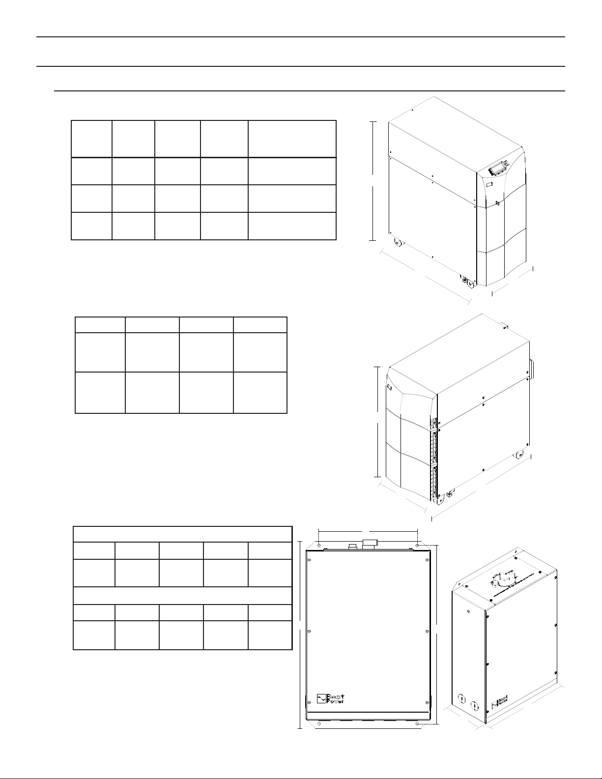
101 Dimensions
Table 1: 2 kVA to 7.5 kVA Dimensions
Table 2: Battery Cabinet Dimensions
Table 3: Bypass Switch Dimensions Figure 2
C
B
A
B
A
C
Model Height
(A)
Width
(B)
Depth with
Internal
(Attached) Bypass
Depth
(C)
2 and 3
kVA
27.25 in.
695 mm
13.5 in.
345 mm
35 in.
890 mm
28.5 in.*
725 mm*
4.5 kVA 30.5 in.
775 mm
13.5 in.
345 mm
31.5 in.
800 mm
25 in.*
635 mm*
6 and
7.5 kVA
38.75 in.
985 mm
13.5 in.
345 mm
39 in.
990 mm
32.5 in.*
825 mm*
32.5 in.*
825 mm*
13.5 in.
345 mm
38.75 in.
985 mm
FBT30
FBT31
FBT32
28.5 in.*
725 mm*
13.5 in.
345 mm
27.25 in.
695 mm
FBT20
FBT21
FBT22
Depth (C)Width (B)Height (A)Model
20 in.
508 mm
E
BPE14
11 in.
280 mm
D
6.75 in.
172 mm
C
14 in.
356 mm
B
21 in.
534 mm
A
20 in.
508 mm
11 in.
280 mm
6.75 in.
172 mm
14 in.
356 mm
21 in.
534 mm
E
BPE12
DCBA
* Add the depth of the battery connection box, 2.6
inches.
* For units with separate battery cabinets, add the depth of the
battery connection box, 2.6 inches.
C
B
D
E
A
Figure 3
Figure 1
Page 6
5
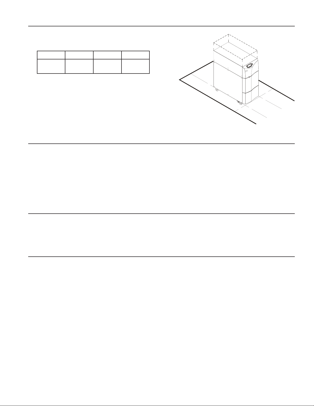
102 Installation and Service Clearances
Table 4: Service Clearances for FERRUPS Figure 4
and Battery Cabinets
Note: If you use flexible conduit to connect the UPS and
battery cabinets, you may be able to achieve the service
clearances by moving the UPS. If this is the case, you
must still leave 12 inches (305 mm) clearance at the front
and back of the UPS for ventilation. Do not block the ventilation
holes on each side of the front panel.
103 Location Requirements
• Install the FERRUPS as close as possible to the equipment it will protect. If this distance is more than 25 feet
(7.6 meters), transient noise can reappear in the electrical distribution system.
• If the FERRUPS batteries are in a separate cabinet, the battery cabinet should be as close to the FERRUPS as
possible. If the batteries will be farther away from the unit than the standard cables allow, call the nearest Best
Power office for assistance.
104 Receiving and Moving the FERRUPS and the Batteries
Note the FERRUPS and battery cabinet weights in the User Manual. Before you unload or move the FERRUPS
or the battery cabinet, make sure your method of moving them is appropriate for their weights.
105 Storage and Operating Environment
Storage Temperature: Store a FERRUPS with internal batteries or a battery cabinet at –20° to +40°
Celsius (–4° to +104° F). Batteries will have a longer shelf life if you store them
below 25° C (77° F). A UPS without internal batteries may be stored at –20° to
+60° Celsius (–4° to +140° F).
Operating Temperature: 0° to 40° Celsius (32° to 104° F), up to 95% relative humidity without
condensation. The batteries last longer if the operating temperature stays below 25°
C (77° F).
Ventilation: The air around the UPS must be clean, dust-free, and free of corrosive chemicals or
other contaminants. The air must be free to circulate around the UPS cabinet and
any battery cabinets. Do not place the UPS or batteries in a sealed room or
container.
High Altitude Operation: The maximum operating temperature drops 1° Celsius per 300 meters above sea
level (2° F per 1000 feet above sea level). Maximum elevation is 3000 meters
(10,000 feet).
12 in.
305 mm
36 in.
915 mm
36 in.
915 mm
12 in.
305 mm
Back (D)Top (C)Front (B)Sides (A)
C
C
C
C
A
A
B
D
B
Page 7

6
106 Bypass Switches
If your FERRUPS model does not have a power cord and plug, you should have a Best Power bypass switch.
The cabinet for these switches may be separate (external) or attached to the back of the UPS (internal).
The bypass switch has four positions (see Table 5 below). In the UPS or LINE positions, AC input power is
still connected to the input terminals inside the UPS once it is installed. To disconnect AC input power
during maintenance or service, turn the bypass switch to SERVICE. For Make-Before-Break switches, please
note that you must press the red button before you can change the switch position.
Table 5: Bypass Switch Positions
Bypass switches may be Make-Before-Break (MBB) or Break-Before-Make (BBM).
Make-Before-Break switches make a new connection before they break the present connection. For example, if
you turned the switch from “UPS” to “LINE,” the bypass switch would connect your protected equipment to AC
input power before disconnecting the equipment from UPS output power. Make-Before-Break switches are not
for use with 208 VAC.
Break-Before-Make switches break the present connection before they make a new one. If you turned a BreakBefore-Make switch from “UPS”to “LINE,” the switch would disconnect your protected equipment from UPS
output power before connecting the equipment to AC input power.
Bypass switches come in four models, and each model has its own ratings for current and voltage. Table 6 below
lists the ratings and weights for Best Power bypass switches.
Table 6: Bypass Switch Ratings and Weights
Switch Position Explanation
LINE Connects the loads (protected equipment) directly to AC line input and disconnects UPS output. AC
line input is still connected to the UPS itself.
OFF Disconnects the protected equipment from both UPS output power and AC input power.
SERVICE
UPS
Like the LINE position, SERVICE connects the loads (protected equipment) directly to AC line input
and disconnects UPS output. However, since SERVICE also disconnects AC input, this is the
appropriate switch position during UPS maintenance or repair.
Connects the UPS output to the protected equipment.
Bypass Switch Model Ratings, Continuous Weight (lbs/kg)
BPE12
(External Bypass Switch)
40A/300VAC (CSA)
50A/300VAC (UL, TÜV)
27 lbs. / 12.3 kg
BPE14
(External)
80A/300VAC 31 lbs. / 14.1 kg
Internal Bypass Switch for
2 kVA and 3 kVA Models
40A/300VAC (CSA)
50A/300VAC (UL, TÜV)
Internal Bypass Switch for
4.5, 6 and 7.5 kVA Models
80A/300VAC
Page 8
7
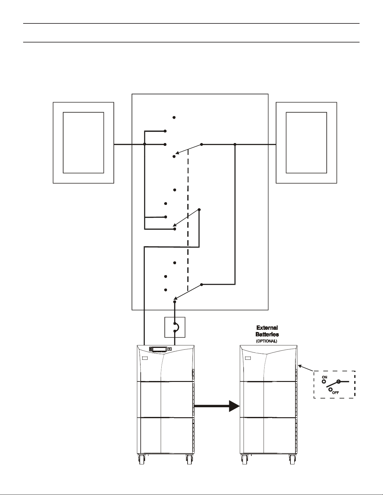
200 Overview of UPS Installation
Figure 6 below shows a typical installation for FERRUPS units that do not have an input power cord and plug.
This diagram shows a unit with a separate battery cabinet and a separate bypass switch. In units with internal
bypass switches, the switch is attached to the back of the UPS, and the UPS is already wired to the switch.
Typical Installation with an External (Separate) Bypass Switch
Figure 6
Building
Service
Panel
External Bypass Switch
Load
Distribution
Panel
UPS
UPS
OFF
OFF
SERVICE
SERVICE
LINE
LINE
UPS
OFF
SERVICE
LINE
UPS
Output
DC Switch
(on Back of Cabinet)
Page 9

300 AC Installation of the UPS and Bypass Switch
(for Qualified Personnel Only)
301 Starting ACInstallation
CAUTION
Read the cautions below before you begin AC installation:
A.All UPS units contain hazardous AC and DC voltages. Because of this, a qualified electrician must install
the UPS and AC line service. The electrician must install AC line according to local and national codes.
B.This equipment relies on protection devices in the building installation. These devices must be installed
within sight of the UPS.
C.Before you install, maintain, or service the UPS, always remove or shut off all sources of AC and DC
power and shut off the UPS. You must disconnect AC line input at the service panel, turn the DC switch
OFF and shut the UPS down to make sure it will not supply output voltage.
D.Whenever AC and/or DC voltage is applied, there may be AC voltage at the UPS terminals; this is true
because the UPS can supply power from AC input or from its batteries. To avoid equipment damage or
personal injury, always assume that there may be voltage at the UPS terminals.
E.Before you install the bypass switch, make sure that the bypass switch is OFF.
F.To reduce the risk of fire or electric shock, install the FERRUPS and the batteries in a temperature-
controlled and humidity-controlled indoor area free of conductive contaminants. See Section 105 for
operating environment specifications.
1.Find the FERRUPSID label on the back panel, and note the following:
Model Number:__________ Input Voltage:__________ Output Voltage:__________
2.Next, find the bypass switch’s ID label, and write down the following:
Model Number:__________ Make-Before-Break (MBB) or Break-Before-Make (BBM)? __________
External (Separate) or Internal (Attached)? __________
3. Now, answer the questions below. Remember that the FERRUPS provides single-phase power only.
a. Does the input voltage at the AC service panel match the input voltage on the UPS ID label?
Service panel voltage: ________ = UPS Input Voltage: ________ lYes lNo
b. Does the output voltage on the UPS ID label match the voltage your loads (protected equipment) will
need?
Load voltage: ________ = UPS Output Voltage: ________ lYes lNo
If the answer to either a. or b. is No, call the nearest Best Power office for assistance.
8
Page 10

4. Now use the information you wrote down in steps 1-3 to find the Installation Wiring Diagram that applies to
your FERRUPSinstallation. If the bypass switch is external (separate), use Table 7. If it is internal (attached),
use Table 8.
Table 7: Installation Wiring Diagrams for Units with External Bypass Switches
Use These Diagrams:Bypass Switch TypeInput and Output VAC
120 input and 120 output
127 input and 127 output
220 input and 220 output
(except Mexico)
Make-Before-Break or Break-Before-Make
Break-Before-Make only.
Make-Before-Break or Break-Before-Make
Figure 10 and Figure 13A
Figure 10 and Figure 13C
Figure 10 and Figure 13D or 13F
230 input and 230 output
240 input and 240 output
208 input and 208 or 240 output
208 input and 120/208 output
208 input and 120/240 output
220 input and 220 output (Mexico)
220 input and 220 output
220 input and 127 output**
230 input and 230 output
240 input and 208 output**
240 input and 120/240 output
* With a step-up or step-down transformer.
** Call Best Power for a) single-phase installations that do not have the same input and output voltage, or b) split-
phase installations that require 220 or 127 VAC.
Make-Before-Break or Break-Before-Make
Make-Before-Break or Break-Before-Make
Break-Before-Make only.
Break-Before-Make only.
Break-Before-Make only.
Make-Before-Break or Break-Before-Make
Make-Before-Break or Break-Before-Make
Break-Before-Make only.
Make-Before-Break or Break-Before-Make
Break-Before-Make only.
Make-Before-Break or Break-Before-Make
Figure 10 and Figure 13E or 13G
Figure 10 and Figure 13A or 13H
Figure 11 and Figure 13B
Figure 11 and Figure 13B
Figure 11 and Figure 13A
Figure 11 and Figure 13C
Figure 11 and Figure 13D
Call Best Power.**
Figure 11 and Figure 13E
Call Best Power.**
Figure 11 and Figure 13A
Figure 12 and Figure 13AMake-Before-Break or Break-Before-Make208 or 480 Source*/ 240 Input
Table 8: Installation Wiring Diagrams for Units with Internal Bypass Switches
Use This Diagram:Bypass Switch TypeInput and Output VAC
120 input and 120 output
127 input and 127 output
220 input and 220 output (except Mexico)
230 input and 230 output
240 input and 240 output
208 input and 208 output
208 input and 120/208 output
208 in put and 120/240 output
220 input and 220 output (Mexico)
230 input and 230 output
240 input and 120/240 output
For 127 VAC, Break-Before-Make only.
For 208 VAC,
Break-Before-Make only.
Figure 15Make-Before-Break or Break-Before-Make
Figure 16Make-Before-Break or Break-Before-Make
220 input and 127 output**
240 input and 208 output**
208 or 480 Source*/ 240 Input
* With a step-up or step-down transformer.
** Call Best Power for a) single-phase installations that do not have the same input and output voltage, or b) split-
phase installations that require 220 or 127 VAC.
Make-Before-Break or Break-Before-Make
Break-Before-Make only.
9
Call Best Power.**
Figure 17
Page 11
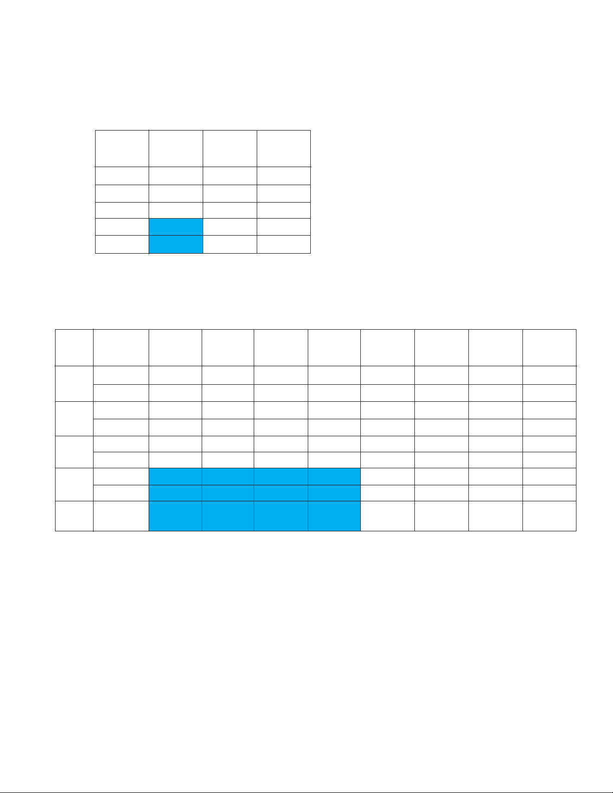
5.Now, refer to the wiring diagram that you selected in step 3, and use Tables 9 and 10 below to find the
proper size circuit breaker for your installation. Table 9 shows the required input circuit breaker size for U.S.
installations. Table 10 shows the input current for each voltage; size input overcurrent protection according
to local codes. In the U.S., use the circuit breaker size and Table 11to size the wiring. In other areas, size
wiring according to local code, making sure you use 75° C copper wire.
Table 9: Required Input Circuit Breaker Sizes for U.S. Installations (60 Hz)
UPS
Model
240V208V120V
15-amp15-amp30-amp2 kVA
20-amp20-amp40-amp3 kVA
25-amp25-amp50-amp4.5 kVA
35-amp35-amp6 kVA
45-amp45-amp7.5 kVA
Table 10: Input Current (Size input overcurrent protection according to local codes.)
UPS
Model
2 kVA
3 kVA
4.5
kVA
60 Hz 28 amps28 amps28 amps28 amps
6 kVA
50 Hz 28 amps28 amps28 amps28 amps
115V110VFrequency 240V230V220V208V127V120V
22 amps22 amps60 Hz 12 amps12 amps12 amps12 amps22 amps22 amps
22 amps22 amps50 Hz 12 amps12 amps12 amps12 amps22 amps22 amps
30 amps30 amps60 Hz 16 amps16 amps16 amps16 amps30 amps30 amps
30 amps30 amps50 Hz 16 amps16 amps16 amps16 amps30 amps30 amps
40 amps40 amps60 Hz 20 amps20 amps20 amps20 amps40 amps40 amps
40 amps40 amps50 Hz 20 amps20 amps20 amps20 amps40 amps40 amps
7.5
kVA
60 Hz 36 amps36 amps36 amps36 amps
10
Page 12

Table 11: United States Recommended AWG and mm2Wire Sizes
For U.S. installations, read this Important Note!
2
This table lists the AWG and mm
wire size for each circuit breaker
size shown on the wiring diagrams. The minimum recommended
circuit breaker sizes for each model and voltage application are
listed on the wiring diagrams.
The conductor size shall be no smaller than the 75° C wire size
based on the ampacities given in Tables 310-316 of the National
Electrical Code, ANSI/NFPA 70-1993, and article 220. All circuit
conductors, including the neutral and equipment grounding
conductors, must be the same size (ampacity) wire. Code may
require a larger AWG size than shown in this table because of
temperature, number of conductors in the conduit, or long service
runs. Follow local code requirements.
For this Input
Circuit Breaker
Size...
15, 20 12 3.31
25, 30 10 5.26
35, 40, 45, 50 8 8.36
60 6 13.30
70, 80 4 21.15
90, 100 3 26.67
110 2 33.62
125 1 42.11
150 1/0 53.49
Use this Size 75° C
Copper Wire
AWG mm
6.Size the UPS output overcurrent protection device (fuse or circuit breaker) according to local code
requirements. Do not exceed the ratings in Table 12. The table below shows the maximum permitted
overcurrent protection device ratings; these are also the ratings recommended for U.S. applications.
2
Table 12: Maximum Permitted UPS Output Overcurrent Protection Device Rating
UPS
Model
120/208
120 and/or
240
7.If your model has an externalbypass switch, go on to Section 302below.
If your model has an internal(attached) bypass switch, go to Section 303on page 20.
230220208 only127/220127 only
9 A10 A15 A16 / 10 A16 A25 / 15 A25 / 15 A2 kVA
14 A14 A20 A24 / 14 A24 A35 / 20 A35 / 20 A3 kVA
20 A21 A30 A36 / 21 A36 A50 / 25 A50 / 30 A4.5 kVA
27 A28 A40 A48 / 28 A48 A70 / 35 A70 / 40 A6 kVA
33 A35 A45 A60 / 35 A60 A80 / 40 A80 / 45 A7.5 kVA
11
Page 13
12
302 Installing Models with External Bypass Switches
1. Mount the bypass switch within sight of the UPS. If you do not have a Best Power bypass switch, or if the
fuse box or panel is out of sight, you must install a separate disconnect switch next to the UPS.
2. Remove the six screws in the bypass switch front panel and remove the panel. Remove the foam packing
material that is inside the bypass switch. Then, remove knockouts in the bottom of the bypass switch for AC
Line Input, AC to UPS Input, AC from UPS Output, and AC to the UPS-protected equipment (loads).
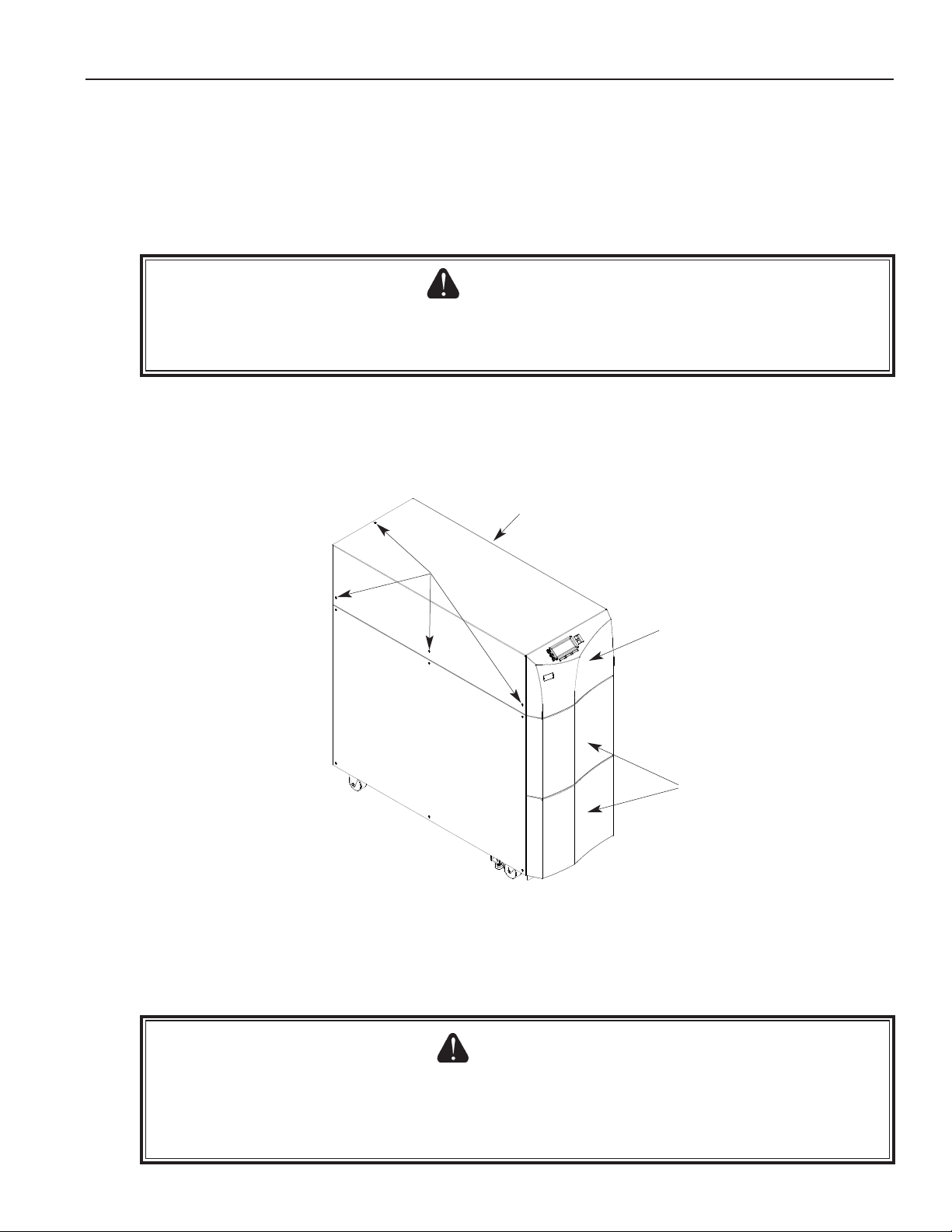
3. Next, remove the top portion of the UPS cover.
To remove the top UPS cover, first pull the top front panel out slightly until it clicks once; the holes in the
right side of the panel can help you do this. Do not strain the ribbon cable behind this panel. If you need
to remove the panel completely, you can disconnect the ribbon cable, but the display will not operate until
you reconnect it. Remove the three screws on each side of the UPS and one screw on the top of the UPS
(toward the back). Then, lift the cover off the UPS. See Figure 7.
4. Remove the knockouts in the FERRUPS back panel for AC Input and AC Output.
5. Install the conduit adapters. AC Input and AC Output conductors must be run through separate conduit. UPS
output circuits shall be installed in dedicated conduit systems and not shared with other electrical circuits.
CAUTION
To prevent electrical shock or damage to your equipment, make sure the FERRUPS is OFF before you
remove the cover. The circuit breaker or disconnect switch must also be off at the AC input service panel.
Remove these
screws.
Pull this panel forward until it
clicks once. DO NOT STRAIN
THE RIBBON CABLE BEHIND
THIS PANEL. If you need to
remove the panel,
disconnect the ribbon cable first.
The display will not operate with
the cable disconnected.
These panels are not
attached when you receive
the UPS. To attach them,
see the Startup section of
the
User Manual
.
Remove three
screws on this
side.
CAUTION
To prevent electrical shock or damage to your equipment, make sure the AC input is OFF at the service
panel and the bypass and AC Disconnect switches are OFF before you connect any wires to the bypass
switch terminal strip.
Figure 7
Page 14
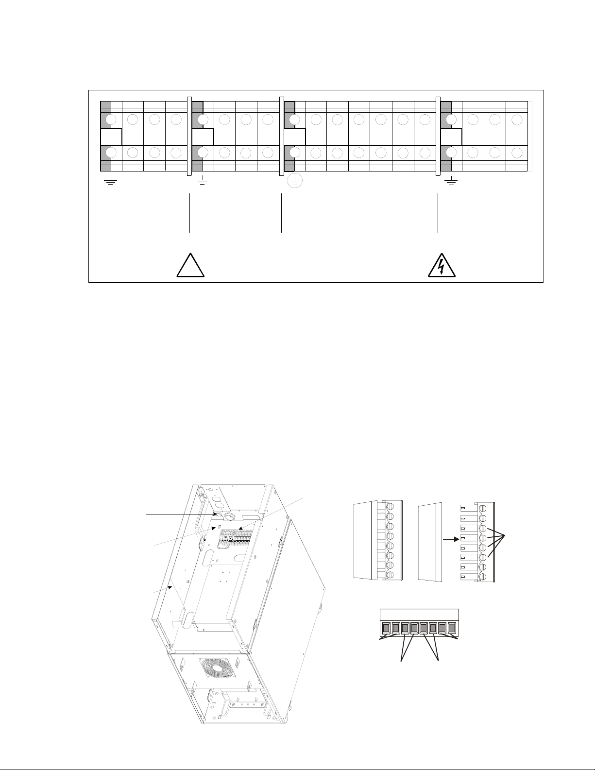
6.Find the terminal strip inside the bypass switch. Using the label on the back of the bypass switch’s access
panel and the Installation Wiring Diagram for your UPS, make the terminal strip connections and tighten all
connections securely. Use copper wire that is the appropriate size for the current draw. See Figure 8 for a
sample label.
12
3
N
AC TO UPS
PROTECTED
LOADS
5
4
L2 L2
6
7111112
89
L1
N
AC FROM
UPS OUTPUT
10
10
N
L1
LINE AC INPUT
12
13
14
1516
L2
N
L1
L2L1
AC TO
UPS INPUT
REFER TO WIRING DIAGRAMS IN THE INSTALLATION MANUAL.
!
Figure 8
7.Find the proper output neutral-to-ground connection in Figure 13 on pages 18-19. At the UPS terminal strip,
connect the neutral-to-ground (neutral-to-earth) wire to the proper output terminal before making any other
connections to the UPS. The neutral-to-ground wire is a green and yellow wire labeled WIA-0424. One end
of this wire is already connected to ground (earth) on the UPS terminal strip.
8.Notice that there is a cable routed out of the left side of the bypass switch cabinet. The wires in this cable
must be connected to the UPS logic board to provide bypass status signals to the UPS. To connect the wires,
follow the steps below. If you plan to use the Emergency Power Off feature, see Appendix A.
USE COPPER CONDUCTORS ONLY.
LAB-1918
a) Route the wires through the UPS grommet shown below and to connector J13 on the logic board.
b) Pull the 8-pin connector at J13 apart as shown. The portion you remove from the connector has 8 possible
connection points.
J13 Connector
Terminal
Grommet for
bypass switch
and EPO wires
Tie-wrap bypass
switch and EPO
wires here
Connect bypass
switch and EPO
wires to J13
Figure 9
DIN Rail
Strip
13
Not
Used
87
65432
Bypass
Status
(White
and
Black
Wires)
Loosen
these
screws.
Tighten
them
after making
connections.
1
EPO
Inverter
Disable
(MBB Red and
Black
Wires)
Page 15

c) Loosen the standard screws on the J13 connector as shown in Figure 9.
d) If your bypass switch is Make-Before-Break (MBB), connect the red and black pair of wires to the
terminals marked 3 and 4 in Figure 9, with the red wire going to 3 and the black wire going to 4.
e) For all external bypass switches, connect the white and black pair of wires to 5 and 6, with the white wire
going to 5 and the black wire going to 6.
Note:If you need to make a connection for an Emergency Power Off signal, complete the steps in
Appendix Abefore you go on.
f) Tighten the screws to secure the connections (torque specification is 2.61 inch-pounds/0.3 N-m), and
reattach the connector to J13 on the logic board.
g) Use the tie-wraps provided to secure the cable. See Figure 9.
9.Using the Installation Wiring Diagram (Figure 10, 11,or 12) for your UPS, make the UPS terminal strip
connections and complete the ACinstallation wiring. Read the notes with each diagram carefully. See
Figure 13for UPS terminations.
Make all connections exactly as shown on the Installation Wiring Diagram to make sure the phasing is
correct. Good ground connections are necessary to reduce electrical noise and make UPS and load operation
safe. Follow the grounding guidelines on the installation wiring diagram.
Torque for these connections should be 10.6-12.3 inch-pounds (1.2-1.4 Newton-meters).
10.If your UPS has one or more separate battery cabinets, go on to Section 400to install them. If not, go to
Section 500to set UPS parameters and perform the phase check.
14
Page 16
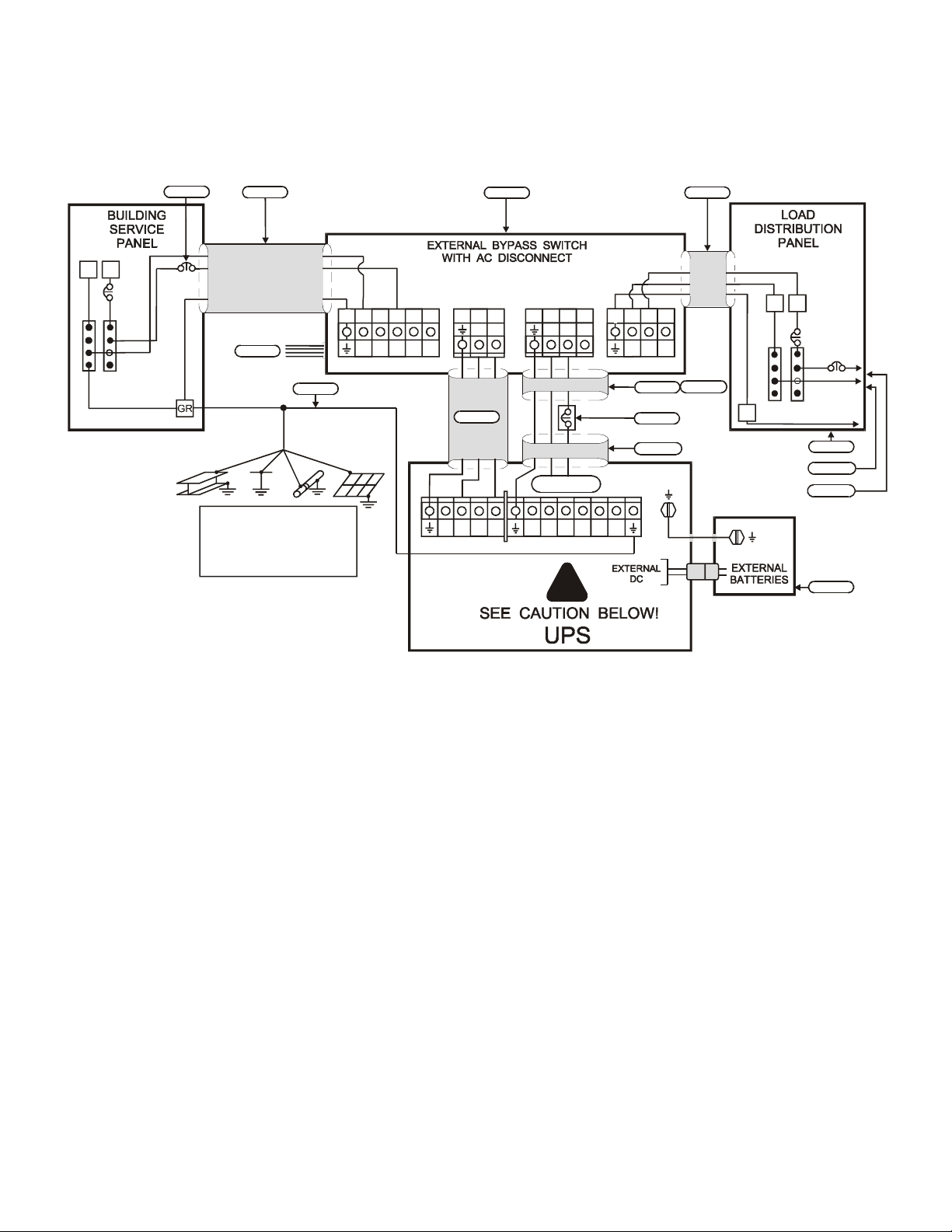
Figure 10: Installation Wiring Diagram for 2, 3, 4.5, 6, and 7.5 kVA FERRUPSModels
with External Bypass Switch (L - N)
• 120 input and 120 output • 127 input and 127 output (Break-Before-Make only)
• 220 input and 220 output (except Mexico) • 230 input and 230 output
• 240 input and 240 output
N
L1
Note 1
Note 4
Note 2
BUILDING GROUNDING
ELECTRODE OR
PROTECTIVE EARTH
SYSTEM
Note 2
AC TO
UPS INPUT
96785
1010111112 1314
L1
N NC
AC LINE INPUT
Note 3
L2/NL2/
15
L1
NL1
Note 4
N
L1L1
AC FROM
UPS OUTPUT
NC
N
Note 6
X1X2
X3X4
2341
N
AC TO LOADS
X5
X6
!
L1
NC
Note 4
Note 5
Note 8
Note 4
Note 10
IG
L1
N
TO
LOADS
Note 7
Note 10
Note 11
Note 9
NOTE 1:The customer must provide input overcurrent protection
as stated in NECSection 240-21 or local codes. Size the
protection device according to local code requirements. (See
Tables 9 and 10 on page 10.)
NOTE 2:The UPS bypass switch must be installed within sight of
the UPS. To properly install, complete the voltage and phase
check procedure in Section 500. The wires coming from the
side of the switch must be connected as described in step 8
on pages 13-14.
NOTE 3:The customer must provide and install this ground
(earth) connection per NEC Sections 250-5(d), 250-26, 250-91
and 250-92, or local code requirements. This grounding electrode
conductor must be at least #8 AWG (8.36 mm
2
) per NECtable
250-94. If the UPS input circuit conductors are larger than #8
AWG (8.36 mm2), Best Power requires the grounding electrode
conductor to be the same size (ampacity) as the largest UPS
input circuit conductor. See NEC Section 110-3(b). Conduit is not
considered an acceptable grounding electrode conductor. Best
Power does not recommend routing the grounding electrode
conductor through metallic conduit. This conductor may require
protection from physical damage according to local code
requirements.
NOTE 4:All AC circuit conductors, including the neutral and
equipment grounding conductors, must be the same size
(ampacity), have the same rating (75° C copper wire), and be
sized according to the input circuit breaker. The UPS input and
output conductors must be run through separate conduits.
NOTE 5:The customer must provide output overcurrent
protection. See NECSection 240-21 or local requirements. See
Table 12 on page 11 for maximum output overcurrent protection
device ratings.
NOTE 6:See Figure 13 for proper output wiring termination and
neutral-to-ground (neutral-to-earth) connection.
NOTE 7:For maximum protection against electrical noise, use
isolated ground receptacles. See NECSection 250-74, Exception
#4.
NOTE 8:See Section 102 for installation and service clearances
before installing the UPS. Use flexible conduit on the UPS or the
external battery cabinet if either must be moved.
NOTE 9:External UPS battery cabinets are optional. See
Section 400 for installation instructions.
NOTE 10:UPS output circuits shall be installed in dedicated
conduit systems and not shared with other electrical circuits.
NOTE 11:The load fuse or circuit breaker should be sized to
match the load current requirements. See Table 12.
15
Page 17
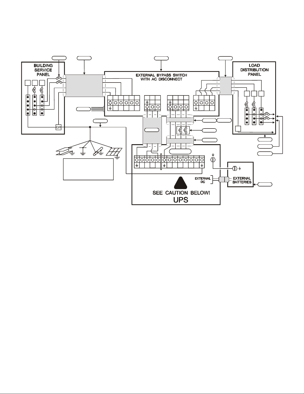
Figure 11: Installation Wiring Diagram for 2, 3, 4.5, 6, and 7.5 kVA FERRUPSModels
with External Bypass Switch (L1, L2, N)
• 208 Input, 120/240 Output • 208 Input, 208 or 240 Output
• 208 Input, 120/208 Output • 60 Hz 220 Input, 220 Output (Mexico)
• 120 or 240 Input, 120/240 Output
N
L2L1
Note 1
Note 4
Note 2
BUILDING GROUNDING
ELECTRODE OR
PROTECTIVE EARTH
SYSTEM
9 6785
1011111212 1315
N
AC LINE INPUT
Note 3
L1
L2
Note 2
AC TO
UPS INPUT
16
L2
L1 L1
Note 4
L2/
L2/
L1
L1
N
N
AC FROM
UPS OUTPUT
N
L2
Note 6
X1X2
X3X4
!
2341
N
AC TO LOADS
Note 4
Note 5
Note 8
X5
X6
L1
L2
Note 4
Note 10
IG
L2
L1
N
TO
LOADS
Note 7
Note 10
Note 11
Note 9
NOTE 1:The customer must provide input overcurrent protection
as stated in NECSection 240-21 or local codes. Size the
protection device according to local code requirements. (See
Tables 9 and 10 on page 10.)
NOTE 2:The UPS bypass switch must be installed within sight of
the UPS. To properly install, complete the voltage and phase
check procedure in Section 500. The wires coming from the
side of the switch must be connected as described in step 8
on pages 13-14.
NOTE 3:The customer must provide and install this ground
(earth) connection per NEC Sections 250-5(d), 250-26, 250-91
and 250-92, or local code requirements. This grounding electrode
conductor must be at least #8 AWG (8.36 mm
2
) per NECtable
250-94. If the UPS input circuit conductors are larger than #8
AWG (8.36 mm2), Best Power requires the grounding electrode
conductor to be the same size (ampacity) as the largest UPS
input circuit conductor. See NEC Section 110-3(b). Conduit is not
considered an acceptable grounding electrode conductor. Best
Power does not recommend routing the grounding electrode
conductor through metallic conduit. This conductor may require
protection from physical damage according to local code
requirements.
NOTE 4:All AC circuit conductors, including the neutral and
equipment grounding conductors, must be the same size
(ampacity), have the same rating (75° C copper wire), and be
sized according to the input circuit breaker. The UPS input and
output conductors must be run through separate conduits.
NOTE 5:The customer must provide output overcurrent
protection. See NECSection 240-21 or local requirements. See
Table 12 on page 11 for maximum output overcurrent protection
device ratings.
NOTE 6:See Figure 13 for proper output wiring termination and
neutral-to-ground (neutral-to-earth) connection.
NOTE 7:For maximum protection against electrical noise, use
isolated ground receptacles. See NECSection 250-74, Exception
#4.
NOTE 8:See Section 102 for installation and service clearances
before installing the UPS. Use flexible conduit on the UPS or the
external battery cabinet if either must be moved.
NOTE 9:External UPS battery cabinets are optional. See
Section 400 for installation instructions.
NOTE 10:UPS output circuits shall be installed in dedicated
conduit systems and not shared with other electrical circuits.
NOTE 11:The load fuse or circuit breaker should be sized to
match the load current requirements. See Table 12.
16
Page 18
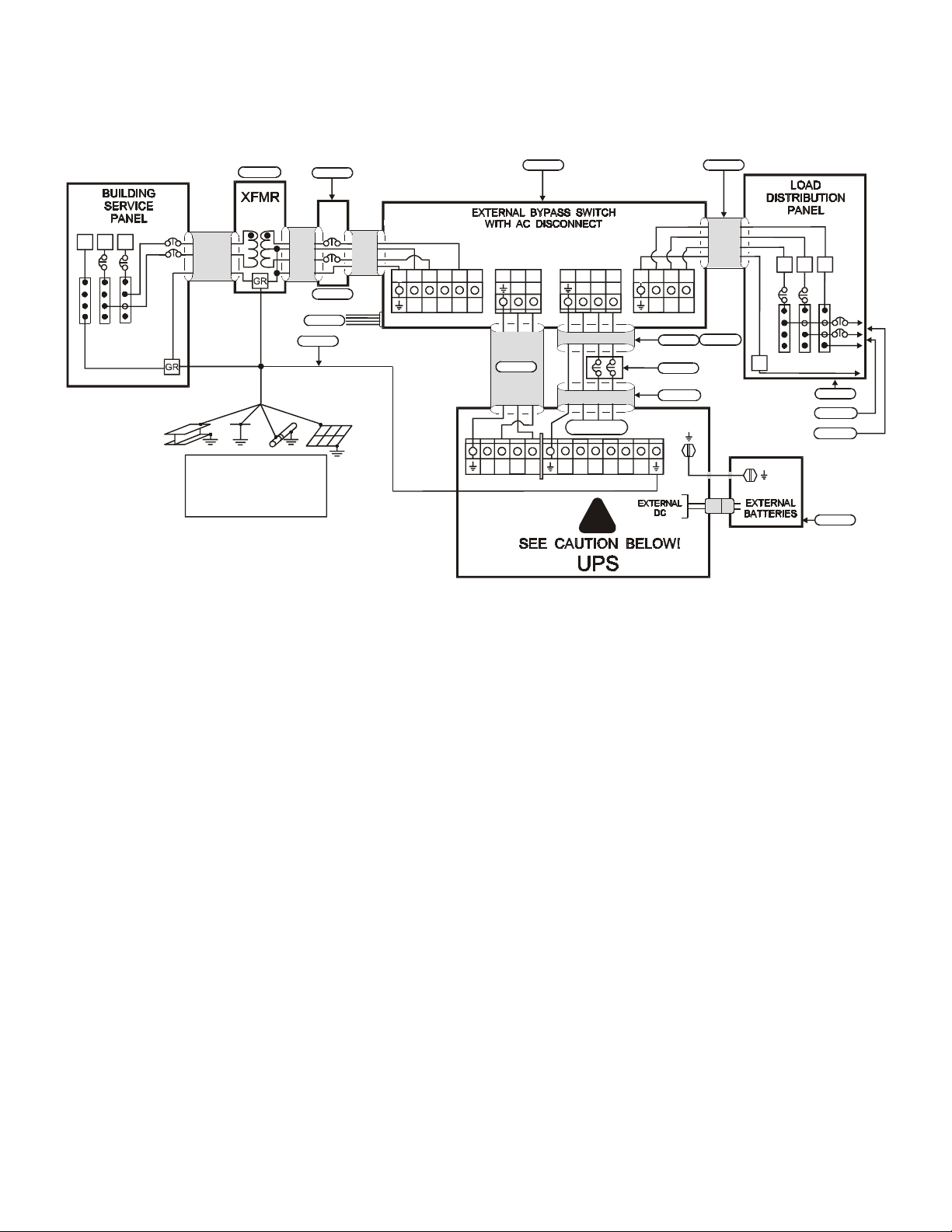
Figure 12: Installation Wiring Diagram for 2, 3, 4.5, 6, and 7.5 kVA FERRUPSModels
with External Bypass Switch (L1, L2, N)
60 Hz 208 or 480 VAC Source with Input Step-Up or Step-Down Isolation Transformer
240 UPS Input - 120/240 UPS Output
Note 10
L1L2
N
Note 1
Note 4
Note 2
Note 3
9
1011111212
L1
L2
N N
AC LINE INPUT
Note 2 Note 4
AC TO
UPS INPUT
131516
L1
Note 4
AC FROM
UPS OUTPUT
L2 L2
6785
L1
N
Note 6
2341
AC TO LOADS
Note 4
Note 5
Note 8
L1
N
L2
L2
L1
Note 11
IG
TO
LOADS
Note 7
Note 11
Note 12
BUILDING GROUNDING
ELECTRODE OR
PROTECTIVE EARTH
SYSTEM
NOTE 1:The customer must provide input overcurrent protection
as stated in NECSection 240-21 or local codes. Size the
protection device according to local code requirements. (See
Tables 9 and 10 on page 10.)
NOTE 2:The UPS bypass switch must be installed within sight of
the UPS. To properly install, complete the voltage and phase
check procedure in Section 500. The wires coming from the
side of the switch must be connected as described in step 8
on pages 13-14.
NOTE 3:The customer must provide and install this ground
(earth) connection per NEC Sections 250-5(d), 250-26, 250-91
and 250-92, or local code requirements. This grounding electrode
conductor must be at least #8 AWG (8.36 mm
2
) per NECtable
250-94. If the UPS input circuit conductors are larger than #8
AWG (8.36 mm2), Best Power requires the grounding electrode
conductor to be the same size (ampacity) as the largest UPS
input circuit conductor. See NEC Section 110-3(b). Conduit is not
considered an acceptable grounding electrode conductor. Best
Power does not recommend routing the grounding electrode
conductor through metallic conduit. This conductor may require
protection from physical damage according to local code
requirements.
NOTE 4:All AC circuit conductors, including the neutral and
equipment grounding conductors, must be the same size
(ampacity), have the same rating (75° C copper wire), and be
sized according to the input circuit breaker. The UPS input and
output conductors must be run through separate conduits.
L2/NL2/
L1L1
N
X1X2X3X4X5
!
X6
Note 9
NOTE 5:The customer must provide output overcurrent
protection. See NECSection 240-21 or local requirements. See
Table 12 on page 11 for maximum output overcurrent protection
device ratings.
NOTE 6:See Figure 13 for proper output wiring termination and
neutral-to-ground (neutral-to-earth) connection.
NOTE 7:For maximum protection against electrical noise, use
isolated ground receptacles. See NECSection 250-74, Exception
#4.
NOTE 8:See Section 102 for installation and service clearances
before installing the UPS. Use flexible conduit on the UPS or the
external battery cabinet if either must be moved.
NOTE 9:External UPS battery cabinets are optional. See
Section 400 for installation instructions.
NOTE 10:For 208 VAC, use a step-up transformer. For 480
VAC, use a step-down transformer. Use an isolation transformer
with a 120/240 grounded center-tapped neutral output.
Do not
use a buck/boost transformer.
NOTE 11:UPS output circuits shall be installed in dedicated
conduit systems and not shared with other electrical circuits.
NOTE 12:The load fuse or circuit breaker should be sized to
match the load current requirements. See Table 12.
17
Page 19
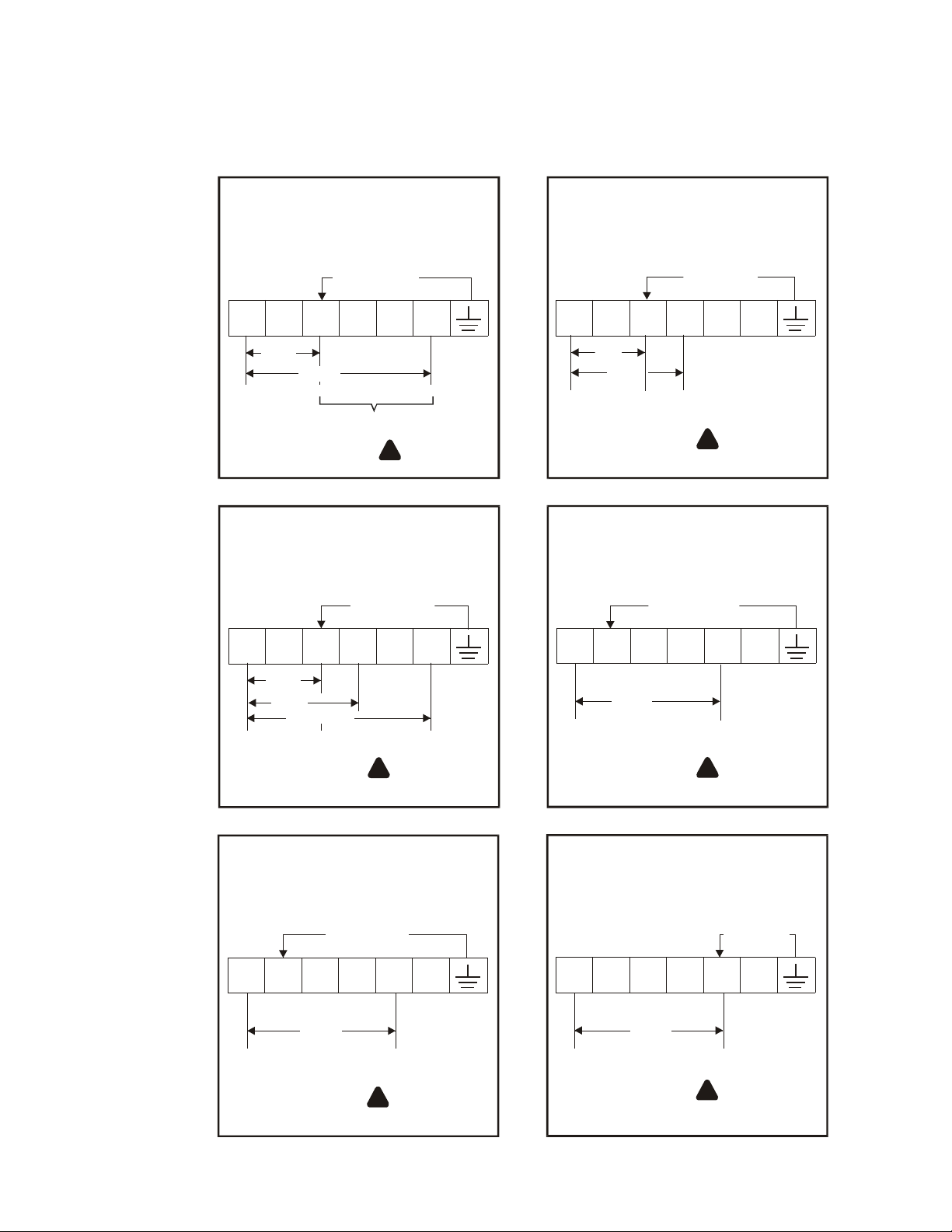
Figure 13: UPS Output Wiring Connections
Find the output wiring configuration (Figure 13A - 13H) for your UPS input voltage and frequency and
UPS output voltage(s). Make the neutral-to-ground (neutral-to-earth) connection first. Then, wire the
output from the UPS as shown. In Section 500, you will set parameter 4 8 to the correct output voltage.
50 or 60 Hz
120/240 Out
Parameter 4 8 set to 240*
N-G BOND
GREEN/YELLOW
X2
X1 X3 X5
120
L1
Do not connect 120V loads
13A
127 Out or 220 Out (Mexico)
Parameter 4 8 set to 254*
X2 X4X1 X3 X5 X6
X4
240
N
between X3 and X6.
!
See Notes 1, 2.
60 Hz
N-G BOND
GREEN/YELLOW
CAUTION
X6
L2
L1
13B
50 or 60 Hz
208 or 120/208Out
Parameter 4 8 set to 208*
N-G BOND
GREEN/YELLOW
X2 X4X1 X3 X5
120
208
L2
N
!
See Notes 1, 2.
50 or 60 Hz
220 Out
Parameter 4 8 set to 220*
N-G BOND
GREEN/YELLOW
X3
X2 X4X1
X6
CAUTION
X6
X5
127
L1
13C
Parameter 4 8 set to 230*
L1
13E
220
CAUTION
254
L2
NL2
!
CAUTION
See Notes 1, 2.
L1
13D
220
50 or 60 Hz
230 Out
Parameter 4 8 set to 220*
N-G BOND
GREEN/YELLOW
X2 X4X1 X3 X5 X6 X2 X4X1
230
L2
!
CAUTION
See Notes 1, 2.
L1
13F
L2
!
See Notes 1, 2.
50 or 60 Hz
220 Out
X3
220
X5
!
220 VOLTS L-N
See Notes 1, 2.
CAUTION
N-G BOND
GREEN/YELLOW
X6
N
CAUTION
18
Page 20
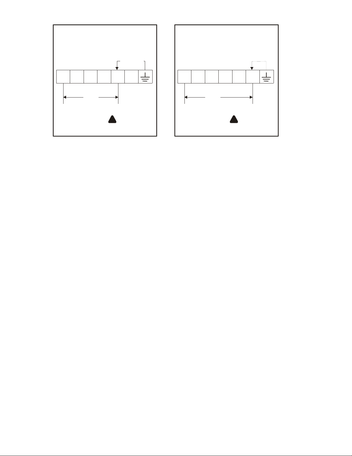
50 or 60 Hz
230 Out
Parameter 4 8 set to 230*
N-G BOND
GREEN/YELLOW
50 or 60 Hz
240 Out
Parameter 4 8 set to 240*
N-G BOND
GREEN/YELLOW
X1
L1
13G
Notes for Figures 13A-13H
NOTE 1: Connect the UPS’ green and yellow neutral-to-ground (neutral-to-earth) wire (N-G bond) to the UPS output
terminal indicated.
NOTE 2: See Table 12 on page 11 for maximum output overcurrent device ratings.
See Section 500 to set the Output Voltage Reference parameter.
230
X4
N
!
CAUTION
230 VOLTS L-N
See Notes 1, 2.
L1
13H
X3 X5 X6 X2
X2
X3 X5 X6
X4X1
240
N
!
CAUTION
240 VOLTS L-N
See Notes 1, 2.
19
Page 21
303 Installing Models with Internal (Attached) Bypass Switches
1.The internal bypass switch is attached to the back of the UPS. Remove the screws in the lowerpart of the
bypass switch’s back panel to remove the panel. Then, remove knock-outs in the bottom of the bypass
switch for AC Line Input and AC to UPS-protected equipment (loads).
2.Install the conduit adapters. You must run the AC input service conductor and the AC Output through
separate conduit adapters and separate conduit. UPS output circuits shall be installed in dedicated conduit
systems and not shared with other electrical circuits.
CAUTION
To prevent electrical shock or damage to your equipment, make sure the AC input is OFF at the service
panel and the bypass and AC Disconnect switches are OFF before you connect any wires to the bypass
switch terminal strip.
3.Find the terminal strip inside the bypass switch. Using the label inside the switch and the appropriate
Installation Wiring diagram on the following pages (Figure 15, 16,or 17), make the terminal strip
connections, tightening all connections securely. Use copper wire, and use the appropriate wire size for the
current draw. Figure 14 below shows a sample terminal strip label. Torque specifications for these
connections are 10.6-12.3 inch-pounds (1.2-1.4 N-m).
Important: Make all terminal strip connections exactly as they are shown on the Installation
Wiring Diagram to ensure correct phase relationships, and follow the grounding
guidelines in the Diagram. Good ground connections are necessary to reduce electrical
noise and make operation of the UPS and the loads safe.
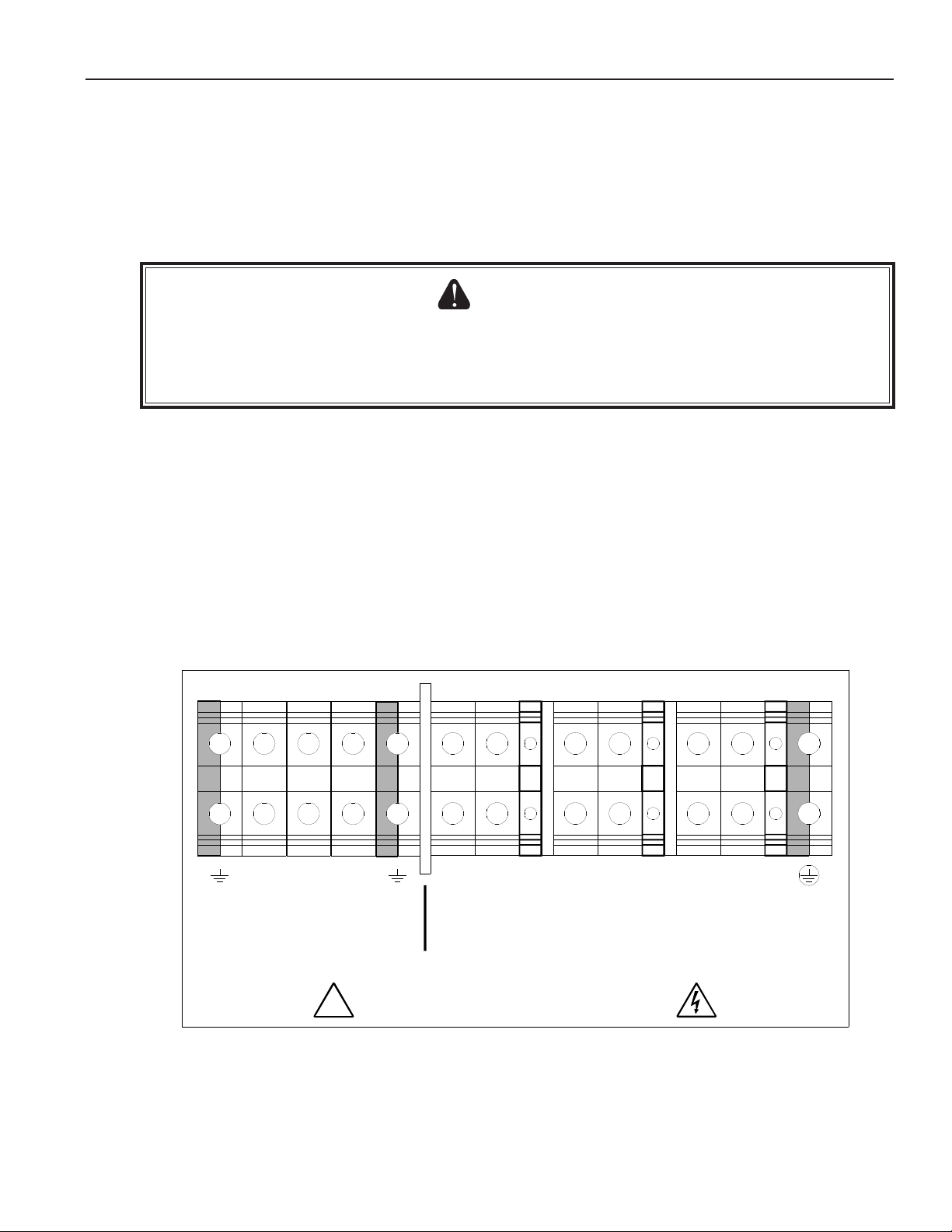
Internal Bypass Switch Terminal Label
N NNL2 L2L2L1 L1L1X1X2X3
AC TO UPS
PROTECTED
LOADS
REFER TO WIRING DIAGRAMS IN THE INSTALLATION MANUAL.
USE COPPER CONDUCTORS ONLY.
!
LINE AC INPUT
LAB-1919
Figure 14
4.If your UPS does not have a separate battery cabinet (external batteries), go to Section 500to set UPS
parameters and perform the phase check.
If your model has external batteries, go to Section 400, Installing the Batteries and DC wiring. Then, go to
Section 500.
20
Page 22
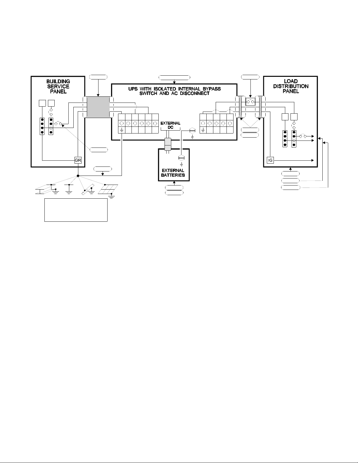
Figure 15: Installation Wiring Diagram for 2, 3, 4.5, 6, and 7.5 kVA FERRUPSModels
with Internal Bypass Switch (L1 - N)
• 120 input and 120 output • 127 input and 127 output (Break-Before-Make only)
• 220 input and 220 output (except Mexico) • 230 input and 230 output
• 240 input and 240 output
L1
N
BUILDING GROUNDING
ELECTRODE OR
PROTECTIVE EARTH
SYSTEM
Note 4
Note 1
Note 3
NC
L1
AC LINE INPUT
Notes 2 & 7
N
Note 8
Note 7
NOTE 1:The customer must provide input overcurrent protection
as stated in NECSection 240-21 or local codes. Size the
protection device according to local code requirements. (See
Tables 9 and 10on page 10.)
Note 5
L1
N
TO
NCX1X2X3
AC TO LOADS
Note 9
Note 4
LOADS
Note 6
Note 9
Note 10
NOTE 5:The customer must provide output overcurrent
protection. See NECSection 240-21 or local requirements. See
Table 12on page 11 for maximum output overcurrent protection
device ratings.
NOTE 2:The UPS bypass switch must be installed within sight of
the UPS. To properly install, complete the voltage and phase
check procedure in Section 500.
NOTE 3:The customer must provide and install this ground
(earth) connection per NEC Sections 250-5(d), 250-26, 250-91
and 250-92, or local code requirements. This grounding electrode
conductor must be at least #8 AWG (8.36 mm
2
) per NECtable
250-94. If the UPS input circuit conductors are larger than #8
AWG (8.36 mm2), Best Power requires the grounding electrode
conductor to be the same size (ampacity) as the largest UPS
input circuit conductor. See NEC Section 110-3(b). Conduit is not
considered an acceptable grounding electrode conductor. Best
Power does not recommend routing the grounding electrode
conductor through metallic conduit. This conductor may require
protection from physical damage according to local code
requirements.
NOTE 4:All AC circuit conductors, including the neutral and
equipment grounding conductors, must be the same size
(ampacity), have the same rating (75° C copper wire), and be
sized according to the input circuit breaker. The UPS input and
output conductors must be run through separate conduits.
NOTE 6:For maximum protection against electrical noise, use
isolated ground receptacles. See NECSection 250-74, Exception
#4.
NOTE 7:See Section 102for installation and service clearances
before installing the UPS. Use flexible conduit on the UPS or the
external battery cabinet if either must be moved.
NOTE 8:External UPS battery cabinets are optional. See
Section 400for installation instructions.
NOTE 9:UPS output circuits shall be installed in dedicated
conduit systems and not shared with other electrical circuits.
NOTE 10:The load fuse or circuit breaker should be sized to
match the load current requirements. See Table 12.
21
Page 23
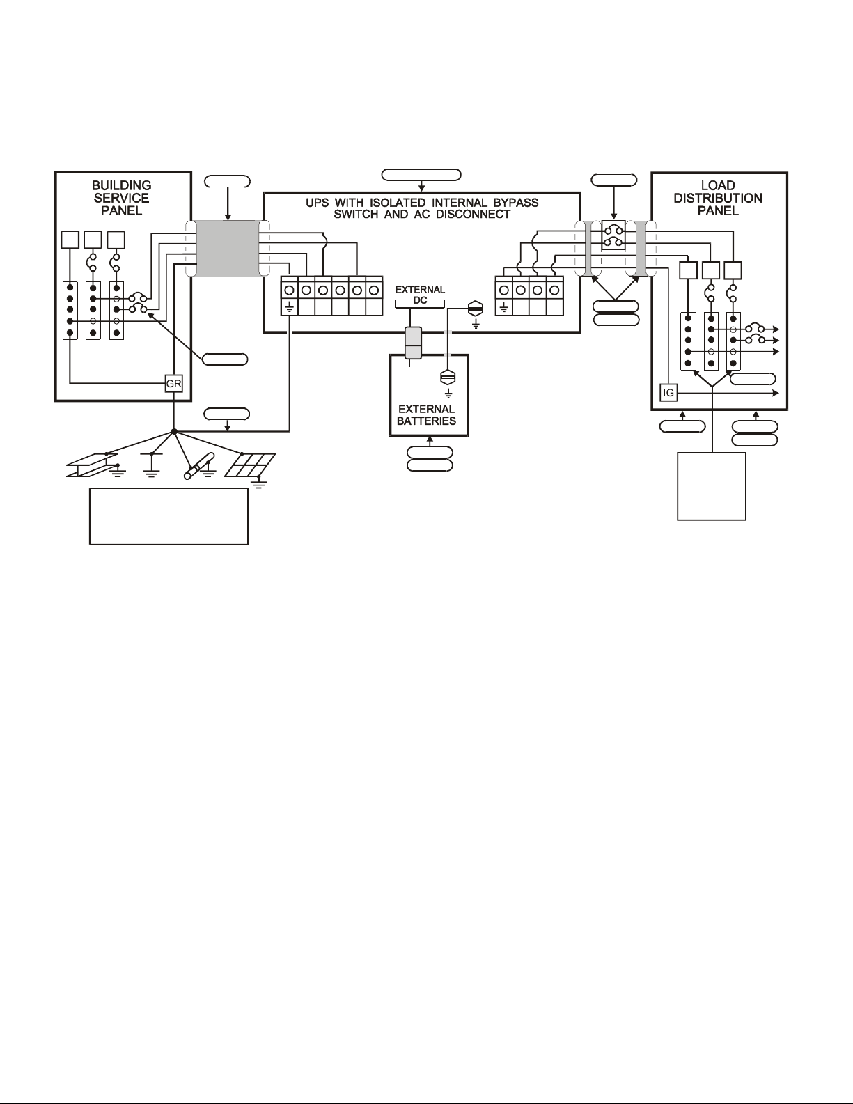
Figure 16: Installation Wiring Diagram for 2, 3, 4.5, 6, and 7.5 kVA FERRUPSModels
with Internal Bypass Switch (L1, L2, N)
• 208 Input, 120/240 Output • 208 Input, 208 Output •220 Input, 220 Output
• 60 Hz 220 Input, 220 Output (Mexico) • 230 Input, 230 Output • 240 Input, 120/240 Output
• 208 Input, 120/208 Output
L1
N
L2
BUILDING GROUNDING
ELECTRODE OR
PROTECTIVE EARTH
SYSTEM
Note 4
Note 1
Note 3
Notes 2 & 7
L2 X3X2
L1
N
AC LINE INPUT
Note 8
Note 7
X1
AC TO LOADS
Note 5
Note 9
Note 4
L1
N
Note 6 Note 9
For 208 VAC
input only. Do
not place any
loads between
L2-N. Only 88
volts available.
L2
LOADS
Note 11
Note 10
TO
NOTE 1:The customer must provide input overcurrent protection
as stated in NECSection 240-21 or local codes. Size the
protection device according to local code requirements. (See
Tables 9 and 10 on page 10.)
NOTE 2:The UPS bypass switch must be installed within sight of
the UPS. To properly install, complete the voltage and phase
check procedure in Section 500.
NOTE 3:The customer must provide and install this ground
(earth) connection per NEC Sections 250-5(d), 250-26, 250-91
and 250-92, or local code requirements. This grounding electrode
conductor must be at least #8 AWG (8.36 mm
2
) per NECtable
250-94. If the UPS input circuit conductors are larger than #8
AWG (8.36 mm2), Best Power requires the grounding electrode
conductor to be the same size (ampacity) as the largest UPS
input circuit conductor. See NEC Section 110-3(b). Conduit is not
considered an acceptable grounding electrode conductor. Best
Power does not recommend routing the grounding electrode
conductor through metallic conduit. This conductor may require
protection from physical damage according to local code
requirements.
NOTE 4:All AC circuit conductors, including the neutral and
equipment grounding conductors, must be the same size
(ampacity), have the same rating (75° C copper wire), and be
sized according to the input circuit breaker. The UPS input and
output conductors must be run through separate conduits.
NOTE 5:The customer must provide output overcurrent
protection. See NECSection 240-21 or local requirements. See
Table 12 on page 11 for maximum output overcurrent protection
device ratings.
NOTE 6:For maximum protection against electrical noise, use
isolated ground receptacles. See NECSection 250-74, Exception
#4.
NOTE 7:See Section 102 for installation and service clearances
before installing the UPS. Use flexible conduit on the UPS or the
external battery cabinet if either must be moved.
NOTE 8:External UPS battery cabinets are optional. See
Section 400 for installation instructions.
NOTE 9:UPS output circuits shall be installed in dedicated
conduit systems and not shared with other electrical circuits.
NOTE 10:The load fuse or circuit breaker should be sized to
match the load current requirements. See Table 12.
NOTE 11:All 120-volt loads must be connected between N and
L1.
22
Page 24
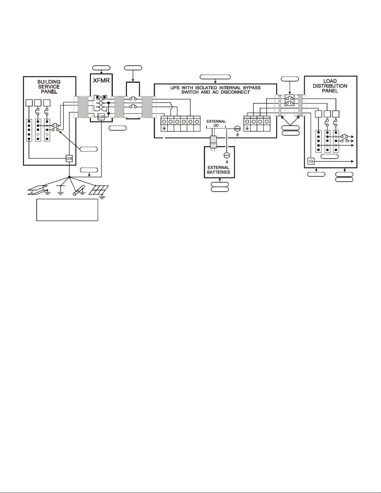
Figure 17: Installation Wiring Diagram for 2, 3, 4.5, 6, and 7.5 kVA FERRUPSModels
with Internal Bypass Switch (L1, L2, N)
60 Hz 208 or 480 VAC Source with Input Step-Up or Step-Down Isolation Transformer
240 UPS Input - 120/240 UPS Output
L1
N
L2
BUILDING GROUNDING
ELECTRODE OR
PROTECTIVE EARTH
SYSTEM
Note 9
Note 1
Note 3
Note 4
Note 1
N
L1
AC LINE INPUT AC TO LOADS
NOTE 1:The customer must provide input overcurrent protection
as stated in NECSection 240-21 or local codes. Size the
protection device according to local code requirements. (See
Tables 9 and 10 on page 10.)
Notes 2 & 7
L2
Note 8
Note 7
X1
X2
X3
Note 5
Note 10
Note 4
L1
L2
N
Note 12
Note 6 Note 10
NOTE 5:The customer must provide output overcurrent
protection. See NECSection 240-21 or local requirements. See
Table 12 on page 11 for maximum output overcurrent protection
device ratings.
TO
LOADS
Note 11
NOTE 2:The UPS bypass switch must be installed within sight of
the UPS. To properly install, complete the voltage and phase
check procedure in Section 500.
NOTE 3:The customer must provide and install this ground
(earth) connection per NEC Sections 250-5(d), 250-26, 250-91
and 250-92, or local code requirements. This grounding electrode
conductor must be at least #8 AWG (8.36 mm
2
) per NECtable
250-94. If the UPS input circuit conductors are larger than #8
AWG (8.36 mm2), Best Power requires the grounding electrode
conductor to be the same size (ampacity) as the largest UPS
input circuit conductor. See NEC Section 110-3(b). Conduit is not
considered an acceptable grounding electrode conductor. Best
Power does not recommend routing the grounding electrode
conductor through metallic conduit. This conductor may require
protection from physical damage according to local code
requirements.
NOTE 4:All AC circuit conductors, including the neutral and
equipment grounding conductors, must be the same size
(ampacity), have the same rating (75° C copper wire), and be
sized according to the input circuit breaker. The UPS input and
output conductors must be run through separate conduits.
NOTE 6:For maximum protection against electrical noise, use
isolated ground receptacles. See NECSection 250-74, Exception
#4.
NOTE 7:See Section 102 for installation and service clearances
before installing the UPS. Use flexible conduit on the UPS or the
external battery cabinet if either must be moved.
NOTE 8:External UPS battery cabinets are optional. See
Section 400 for installation instructions.
NOTE 9: For 208 VAC, use a step-up transformer. For 480 VAC,
use a step-down transformer. Use an isolation transformer with a
120/240 grounded center-tapped neutral output.
Do not use a
buck/boost transformer.
NOTE 10:UPS output circuits shall be installed in dedicated
conduit systems and not shared with other electrical circuits.
NOTE 11:The load fuse or circuit breaker should be sized to
match the load current requirements. Table 12.
NOTE 12:All 120-volt loads must be connected between N and
L1.
23
Page 25

24
400 Connecting the External Battery Cabinet(s)
401 Important Notices
If battery cabinets will be stored, connect them to the UPS every 90-120 days and run the UPS for at least 8
hours to recharge the batteries. The warranty will be voided if batteries are not recharged.
If you have ordered battery cabinet model FBT20 or FBT30, no batteries are installed in the battery cabinet, and
no cables are provided for connecting batteries to each other. When installing batteries, follow all safety
precautions for connecting and servicing batteries in Section 403 below, and follow all precautions
recommended by the battery manufacturer. Do not exceed the DC voltage rating of the UPS.
402 Tools Needed:
• Wire Cutter • 7/16-in. Nutdriver or Wrench • Personal Safety Equipment Required by Local Codes
• Phillips Screwdriver • 1/4-in. Nutdriver or Wrench
403 Safety Information
CAUTION
For Connecting Battery Cabinets:
The battery cabinet’s chassis (ground or earth) must be connected to UPS chassis (ground or earth). Ground additional
battery cabinets to each other. (See the grounding instructions in this document.) See the User Manual for UPS weights
and dimensions. Make sure you are prepared for the weights before you unload or move the UPS or battery cabinets. Do
not make connections to the RS232 communication port if the UPS is connected to a positive ground battery system.
The RS232 ground must be isolated to prevent equipment damage. For assistance, call the nearest Best Power office.
For Servicing or Replacing Batteries:
Full voltage and current are always present at the battery terminals. Keep unauthorized personnel away from
batteries. The batteries used in this system can produce dangerous voltages, extremely high currents, and a risk
of electric shock. They may cause severe injury if the terminals are shorted together or to ground (earth). Be
extremely careful to avoid contacting battery terminals during battery installation. Do not touch uninsulated
battery terminals. Tools must be insulated so that they will not short battery terminals. Do not allow a tool to short a
battery terminal to another battery terminal or to the cabinet. Do not lay tools or metal parts on top of the batteries.
Batteries contain caustic acids and toxic materials and can rupture or leak if mistreated. Released electrolyte is harmful
to the skin and eyes. It may be toxic. Wear protective clothing and eye wear. Remove rings and metal wristwatches or
other jewelry. Do not carry metal objects in your pockets; these objects could fall into the battery cabinet or UPS.
Disconnect battery cabinets from each other before servicing.
A qualified service person who is familiar with battery systems and required precautions must service the
batteries. Batteries must be replaced with Best Power battery number BAT-XXXX. Best Power ’s batteries come
with a two-year warranty; using batteries not supplied by Best Power invalidates any Best Power service
agreement. To ensure continued superior performance of your UPS and to maintain proper charger operation, replace
the batteries in the UPS or battery cabinets with the same number and type of batteries. Replacement batteries should
have the same voltage and ampere-hour rating as the original batteries. Any battery used with this UPS shall comply
with the applicable requirements for batteries in the standard for emergency lighting and power equipment, UL 924. The
installation must conform to national and local codes. For information on battery replacement, call the nearest Best
Power office. BATTERY REPLACEMENT REQUIRES SPECIAL TOOLS AND EQUIPMENT. CALL BEST
POWER BEFORE REPLACING BATTERIES.
Dispose of batteries properly. Assume that old batteries are fully charged. Use the same precautions you would use
when handling a new battery. Do not dispose of battery or batteries in a fire. The battery may explode. Batteries contain
lead. Many state and local governments have regulations for disposing of batteries.
Do You Need to Remove Ground from the Battery Terminal? If local or national code requires grounding either
battery terminal, remove the connection from the terminal to ground (earth) before servicing the batteries. If any battery
terminal is inadvertently grounded, remove the source of ground. Contacting any part of a grounded battery can cause a
risk of electric shock. Electric shock is less likely if you disconnect the ground connection before servicing batteries.
Page 26
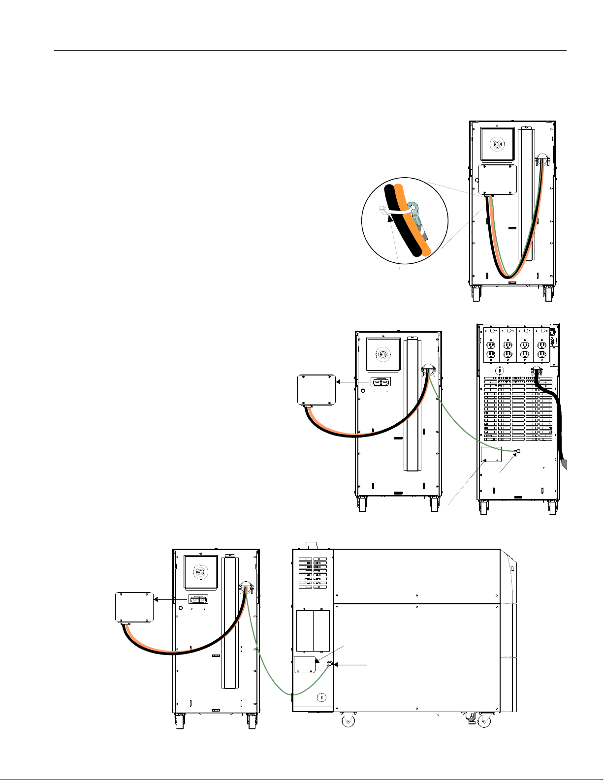
404 Connecting the Battery Cabinet(s)
Note:These steps are for connecting battery cabinets. When the batteries need replacement, you will need
special equipment and instructions. Call the nearest Best Power office for more information.
1.Make sure the UPS is shut down. If the UPS has a power cord and plug, make sure the UPS has been
plugged in to establish a ground connection. If the UPS does not have a power cord
and plug, the UPS should be installed according to the instructions in Section 300 of
this manual.
2.Place the battery cabinet(s) next to the UPS. Leave at least 12 inches
(305 mm) space behind and on the sides of the battery cabinets
for ventilation, and leave 36 inches (910 mm) space at the
front and top. Leave 12 inches (305 mm) space between the
battery cabinet and the UPS.
3.The green ground cable is tie-wrapped with the DC cables on
the back of the UPS. Use a wire cutter to cut the section of tiewrap that is threaded through the ring connector as shown in
Figure 18.DO NOT cut the cables or any of the other
tie-wraps!
4.Remove the bolt that is labeled with the
ground symbol from the back of the UPS.
Then, put this bolt into the ring connector at
Remove
the end of the battery cabinet’s green ground
cable. Use this bolt to attach the ground cable
to the UPS as shown in Figure 19 (or Figure
20 for units with attached bypass switches).
this
box.
Figure 18
CUT HERE.
5.Remove the two screws holding the metal
plate on the back of the UPS. (See Figure 19;
if your UPS has a bypass switch attached,
see Figure 20.) Keep the screws for use later.
6.Pull the DC box out of the battery pack as
shown in Figure 19 (or Figure 20 for units
with attached bypass switches). Remove the
packing material from behind the box.
Remove
this
box.
Figure 19
Remove this plate.
Connect
the ground
wire here.
Remove
this plate.
Connect the
ground wire
here.
Figure 20
25
Page 27
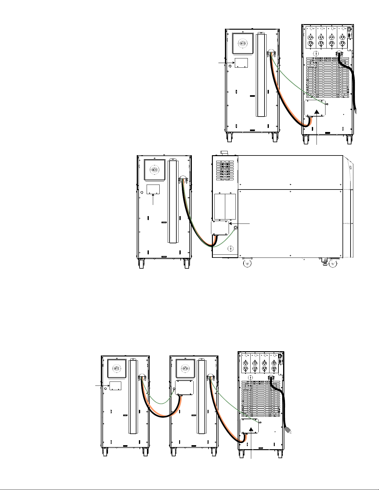
7.Insert the DC box into the back of the UPS as
shown in Figure 21, if your UPS has a bypass
switch attached, see Figure 22.
If your UPS has more than one battery cabinet,
skip step 8 below and go to step 9.
8.If your UPS has only one battery cabinet,attach
the metal plate (removed from the UPS) to the
back of the battery cabinet as shown in Figure
21 or 22. Use the two screws you removed from
the UPS in step 5. You are now finished
connecting the cables. Skip the steps below and
go to Section 405.
9.If your UPS has more than
onebattery cabinet,put the
DC box from the second
battery cabinet into the
connector on the back of
the first battery cabinet as
shown in Figure 23.
10.Put the DC box from the
Attach plate
here.
third battery cabinet into
the connector on the back
of the second battery
cabinet as shown in Figure
23.
Attach plate
here.
Figure 21
Connect box here.
Connect box here.
11.At the third battery cabinet,
attach the metal plate
Figure 22
you removed from the UPS
to the back of the battery
cabinet as shown in Figure 23.
Use the screws that attached the plate to the UPS.
You have finished connecting the battery cabinets. Now, go on to Section 405 to turn on the DC switch.
Attach plate
here.
Figure 23
Connect box here.
26
Page 28
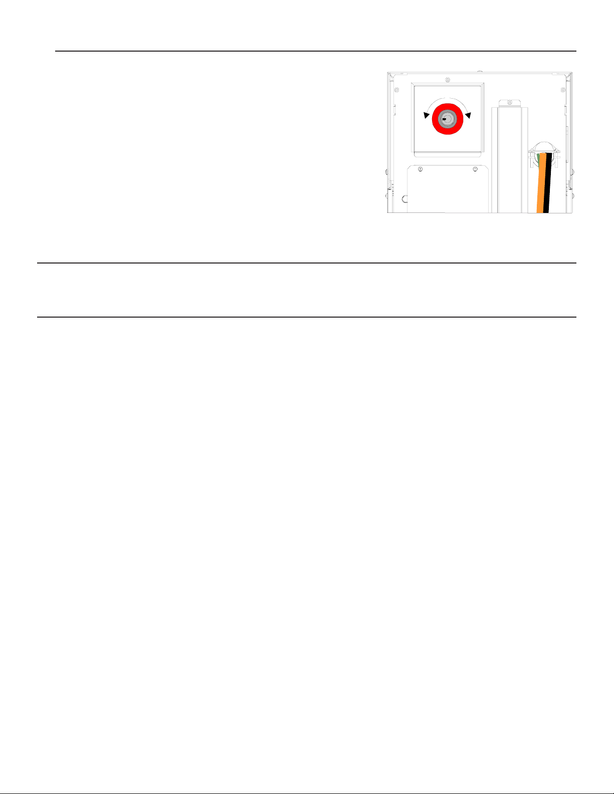
405 Turning the DC Switch On and Off
1.At the back of the battery cabinet, insert the key into the switch,
and turn the key all the way to the right (clockwise).
2.Pull the red knob out (toward you). You can then remove the
key from the switch.
When you need to turn the DC switch off, simply push the red knob
in. The key is not needed.
Important:Go to Section 500 to program the battery parameters.
If your UPS does not have a line cord and plug, you
must also perform the phase check in Section 500.
500 Parameters and Phase Check
(for Qualified Personnel Only)
Figure 24
This section explains how to start the UPS, program parameters that need to be set after installation, and perform
a voltage and phase check. (The voltage and phase check is only for units without line cords and plugs.)
Starting the UPS
1.Make sure that the main circuit breaker in the load service panel is off, or make sure the loads cannot
receive power from the UPS.
2.At the bypass switch, press the red button and turn the switch to “UPS.”
3.At the UPS AC input service panel, turn on the input power to the UPS and the bypass switch.
4.Turn on the DC switch at each battery cabinet (see Section 405 above).
5.At the UPS back panel, press and hold the On/Off switch until the UPS starts. The green light that is next to
the UPS display panel will light, after a short delay.
Parameter Settings
6.This step is only necessary if your UPS has separate battery cabinets. If not, go on to step 7.
When you connect battery cabinets to the UPS, you must change the value of some UPS parameters so the
UPS is programmed for its new battery capacity.
a.First, you must switch from the standard display (showing the UPS mode and the % load) to the menu
display. To do this, press the bottom right button (below “Menu” on the display). The display will show
“1 Enter password.”
b.You must enter the User password before programming the output voltage parameter. Press ¿. A
blinking cursor will appear in the password setting under the first digit.
c.The User password is 377; this means that you must change the display to “0377.” To do this, first press
the middle button below “–>” on the display once to scroll to the second digit. Then, press sthree
times to increase the value of this digit to “3.”
27
Page 29
28
Continue to use the <– and –> buttons to move to the digits that you need to change, and use the s and
t buttons to increase or decrease the value of each digit. When the display shows “0377,” press ¿ to
save the new setting. “User” will appear at the top of the display to show that you have entered the User
password.
d. Press t three times until the display shows “4 System ID.” Then, press ¿. The display will now show
“4 1 Model Number.” Press t five times; the display will show “4 6 Batt Amp Hours.”
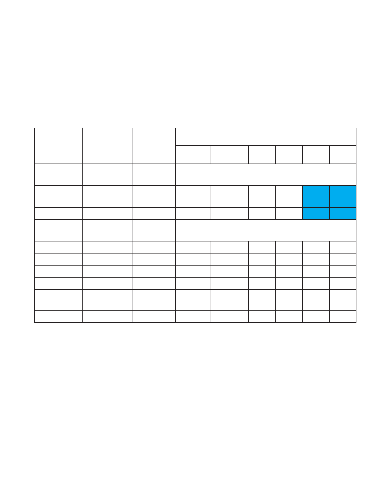
e. Now, check the information on the invoice shipped with your UPS to determine what battery cabinet and
batteries your UPS has. Then, use this information to find the correct ampere-hour rating in Table 13.
Table 13: Battery Ampere-Hour Settings
* Standard 2 kVA units have (4) BAT-0058 batteries. 2 kVA units with the internal extended runtime option have (4) BAT-0053
batteries. Your unit’s invoice should identify the batteries inside the UPS.
** FBT20 and FBT30 battery cabinets do not come with batteries installed. No cables are provided for connecting batteries to
each other.
f. Press ¿. A blinking cursor will appear under the first digit in the setting (value) of this parameter. Notice
that the bottom row of the display changes to “<– –> ESC” to show you the functions of the buttons
below the display. Use the s and t buttons to increase or decrease this digit as needed. Then, use the
button below –> to move to remaining digits, and use the s and t buttons to change the value of each
digit. When the display shows the correct battery ampere-hour rating, press ¿ to save the setting.
7. This step is only necessary if your UPS does not have an input line cord and plug. In order for the
FERRUPS to provide the desired output voltage(s), you must program the Nominal AC Volts Out parameter.
To do this, follow these steps:
a. Use Table 14 to determine the proper setting for the Nominal AC Volts Out parameter.
Battery Cabinet
Number:
Batteries in
UPS:
Batteries in
Battery
Cabinet(s)
Battery Ampere-hour Rating by UPS Model
2 kVA (ext.
runtime)
2 kVA
(standard)
3 kVA 4.5 kVA 6 kVA 7.5 kVA
FBT20
FBT21
(4) BAT-0053
or (4) BAT-0058*
(4) BAT-0053
or (4) BAT-0058*
None**
(4) BAT-0053 62
Add the ampere-hour ratings of each string in the battery cabinet and
the battery string in the UPS to determine the parameter setting.
48 62 62
FBT22 (4) BAT-0053 (8) BAT-0053 9379 93 93
FBT30
FBT31
(4) BAT-0053
(4) BAT-0053
None**
(4) BAT-0483 106
Add the ampere-hour ratings of each string in the battery cabinet and
the battery string in the UPS to determine the parameter setting.
92 106 106 150 150
FBT32 (4) BAT-0053 (8) BAT-0483 181167 181 181 225 225
FBT31 + FBT32 (4) BAT-0053 (12) BAT-0483 256242 256 256 300 300
Two FBT32 (4) BAT-0053 (16) BAT-0483 331317 331 331 375 375
FBT31 + Two
FBT32
(4) BAT-0053 (20) BAT-0483 406392 406 406 450 450
Three FBT32 (4) BAT-0053 (24) BAT-0483 481467 481 481 525 525
Page 30

Table 14: Nominal AC Volts Out Settings
If you have wired the UPS for this output voltage... ...set parameter 4 8 (Nominal AC Volts Out) to this:
220 220
230 230
120 and/or 240 240
208 or 120/208 208
127 and/or 220 254
b.If the display is showing information about the system mode and % load, press the bottom right button
(below “Menu”) to switch to the menu display. The display will show “1 Enter password.”
If the display is already showing the menus, go to step c.
c.If the word “User” is in the upper right corner of the display,the User password has already been
entered; go to step d.
If not,you must enter the User password. First, press the bottom right button (below the word “ESC”)
until there is only one number (one digit) on the top line of the display. Then, press the bottom middle
button (below the word “Top”). The display should show “1 Enter password.” The User password is
0377; this means that you must change the display to “0377.” To do this, first press the middle button
below “–>” on the display twice to scroll to the second digit. Then, press sthree times to increase the
value of this digit to “3.” Continue to use the <– and –>buttons to move to the digits that you need to
change, and use the sand tbuttons to increase or decrease the value of each digit. When the display
shows “0377,” press ¿to save the new setting. “User” will appear at the top of the display to show that
you have entered the User password.
d.If your display is already showing parameter 4 6 (Batt Amp Hours),press ttwice to scroll down to
parameter 4 8 (Nominal AC V Out).
If the display is showing “1 Enter password,”press t three times. The display should show “4 System
ID.” Press ¿; then, press tseven times. The display should now show “4 8 Nominal AC V Out.”
e.Press ¿. A blinking cursor will appear in the setting for AC volts out. Notice that the bottom row of the
display changes to “<– –> ESC” to show you the functions of the buttons below the display. Use
the <– and –>buttons to move to the digits that you need to change in the display, and use the sand t
buttons to increase or decrease the value of each digit. When the digits show the setting you need, press
¿to save the new setting.
Phase Check
If your UPS has a line cord and plug,skip the steps below, turn the FERRUPS off, and push in the DC switch at
each battery cabinet. You have finished installing the FERRUPS. See the User Manual for more information.
If your UPS does not have a line cord and plug,you must follow the steps below to complete the voltage and
phase check.
Note:If your UPS has separate battery cabinets, make sure you connect the cabinets as described in
Section 400 before you perform the voltage and phase check.
29
Page 31

CAUTION
Before you switch the bypass switch, follow the steps below to check for correct operation. To prevent
damage to the loads, make sure the main circuit breaker in the load service panel is off, or make sure the
protected equipment (loads) cannot receive power from the UPS.
8.At the bypass switch, make sure the voltage from the UPS to the loads is close to the voltage from AC line
to the bypass switch. (There may be slight differences.) At the bypass switch terminal strip, find the
measurement points listed below for your bypass switch type. Use an AC voltmeter to measure the voltage
between these points. Record your voltage measurements in the spaces provided below. The voltages in the
first column should be similar to the values in the second column. If the difference is more than a few
volts, check the connections at the terminal strip and correct any wiring problems.If you need help,
call Best Power’s Worldwide Service or the nearest Best Power office.
External Bypass Switch:
AC Line Input AC from UPS Output
L1 to L2 (11 to 12*) __________ 7 to 8* __________
N to L1 (10 to 11*) ___________ 6 to 7* __________
N to L2 (10 to 12*) ___________ 6 to 8* __________
*For some installations, there is no connection at terminals 6, 10, 8, or 12.
Internal Bypass Switch:
AC Line Input AC from UPS Output
L1 to L2 __________ X1 to X2 __________
N to L1 __________ X3 to X1 __________
N to L2 __________ X3 to X2 __________
9.If you have a Break-Before-Make (BBM) bypass switch, go to step 10.
If you have a Make-Before-Break (MBB) bypass switch, make sure the AC voltages from the UPS output
and the AC line input are in phase. To do this, measure the voltage between the following points on the
bypass switch terminal strip. These measurements must not be more than 100 VAC; if they are, call Best
Power’s Worldwide Service or the nearest Best Power office.
External Bypass Switches: 7 to 11 __________
8 to 12 __________
Internal Bypass Switches: UPS terminal L1 to Internal Bypass terminal L1 __________
UPS terminal L2 to Internal Bypass terminal L2 __________
10.Measure the AC voltage between the following points on the bypass switch terminal strip. This reading
must not be more than 1 VAC. If it is, call Best Power’s Worldwide Service or the nearest Best Power
office.
External Bypass Switches: 6 to 10 __________
30
Page 32

11.Now switch the bypass switch to “LINE.” Using the AC voltmeter, make sure that the voltage to your
protected equipment is correct; you can verify the voltage at the Load Distribution Panel or the UPSprotected receptacles for your equipment.
12.Next, switch the bypass switch to “UPS” and verify the voltage to your protected equipment once more.
13.If all of your readings in the voltage and phase check are acceptable, follow these steps:
a.Put the bypass switch cover back on and tighten the screws securely.
b.Turn the FERRUPS off.
c.Push in the DCswitch at each separate battery cabinet to turn off DC.
d.Put the top cover back on the UPS, and reattach all screws. (There are three screws on each side, and
there is one screw on the top.) After you have reattached the top cover, push the front panel back in
place.
e.Turn of the AC LINE Disconnect switch. If you will not be starting the UPS now, you can leave the
bypass switch in the “LINE” position and switch on your protected equipment. Your equipment will be
receiving direct AC input power; it will not be protected until your start the UPS and switch the bypass
switch to “UPS.”
You have finished installing the FERRUPS. To restart the UPS, see the User Manual.
Appendix A: Connections for the Emergency Power
Off (EPO) Signal
Computer rooms often have an emergency shutdown switch (or panic button) that shuts off the power to all
equipment in the computer room. If the UPS’ AC input source is connected to the switch, the switch will shut
off the FERRUPSinput power. However, the UPS will interpret this as a power outage and will continue to
provide output power to the equipment it protects until its batteries run down. To make sure the emergency
shutdown switch can shut off the UPS’ outputpower, use the unit’s remote Emergency Power Off (EPO)
feature.
Your computer room’s emergency shutdown switch must have a set of dedicated contacts between pin 1 and pin
2 of J13. Use a shielded, single twisted pair cable to connect the emergency shutdown switch to the UPS. See
Figure 26. When pin 1 is disconnected from pin 2, the FERRUPS output power is shut off. When this happens,
the FERRUPS will display an “EPO Shutdown” alarm. To restart the UPS after a shutdown, press the On/Off
switch on the UPS back panel, and press a button on the front display panel to confirm the restart.
If your unit has an external (separate) bypass switch,you must also connect wires from the bypass switch to J13
on the UPS logic board. (See Figure 26 on the next page.) It is best to make this connection at the same time
that you connect the bypass wires to J13 (see step 8 in Section 302). To make the connection, follow the steps on
the next page.
1. If the top cover has not already been removed, first pull the top front panel out slightly; the holes in the right
side of the panel can help you do this. Do not strain the ribbon cable behind this panel. If you need to
remove the front panel completely, you can disconnect the ribbon cable first, but the display will not operate
until you reconnect it. Remove the three screws on each side of the UPS and one screw on top of the UPS as
shown on the next page. Then, lift the cover off the UPS.
31
Page 33
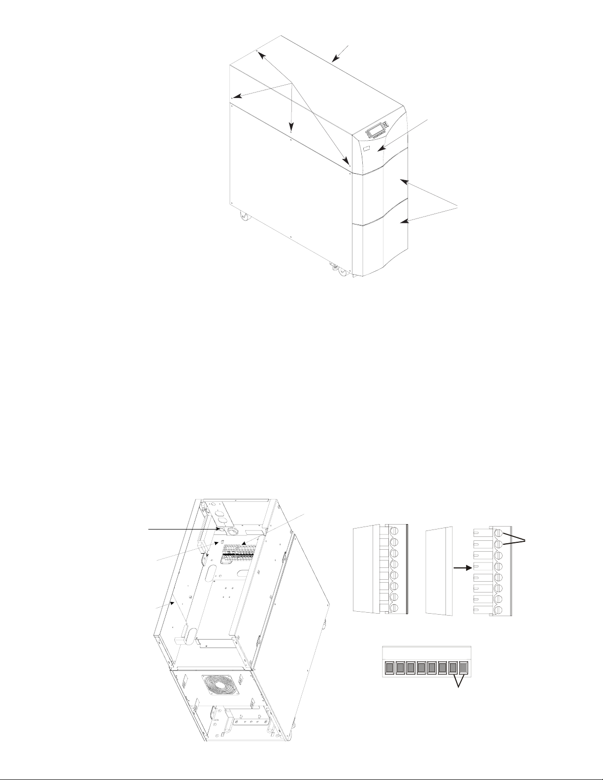
Remove three
screws on this
side.
Remove these
screws.
Pull this panel forward.
DO NOT STRAIN THE RIBBON
CABLE BEHIND THIS PANEL.
If you need to remove the panel,
disconnect the ribbon cable first.
The display will not operate with
the cable disconnected.
These panels are not
attached when you receive
the UPS. To attach them,
see the Startup section of
the
User Manual
.
Figure 25
2. Route the EPO cable through the grommet shown in Figure 26 and to connector J13 on the logic board.
3. Pull the 8-pin connector at J13 apart as shown in Figure 26. The portion you remove from the connector has 8
possible connection points.
4. Loosen the standard screws shown in Figure 26.
5. Connect the twisted pair in the EPO cable to pins 1 and 2 of connector J13. Note that pin 2 is common (signal
ground). If you are also connecting wires from the external bypass switch, go back to Section 302, step 8f.
6. Tighten the screws to secure the connections (torque specification is 2.61 inch-pounds/0.3 N-m), and reattach
the connector to J13 on the logic board.
7. Use the tie-wraps provided to secure the cable. See Figure 26.
8. Place the top cover back on the UPS, and use the screws you removed to reattach the cover. Then, push the
front panel back in place.
Terminal
Grommet for
bypass switch
and EPO wires
Tie-wrap bypass
switch and EPO
wires here
Connect bypass
switch and EPO
wires to J13
DIN Rail
Strip
J13 Connector
1
2
Loosen
these
screws.
Tighten
them after
making
connections.
Figure 26
8 7 6 5 4 3 2 1
EPO
2 = Common/Ground
32
 Loading...