

Page 1
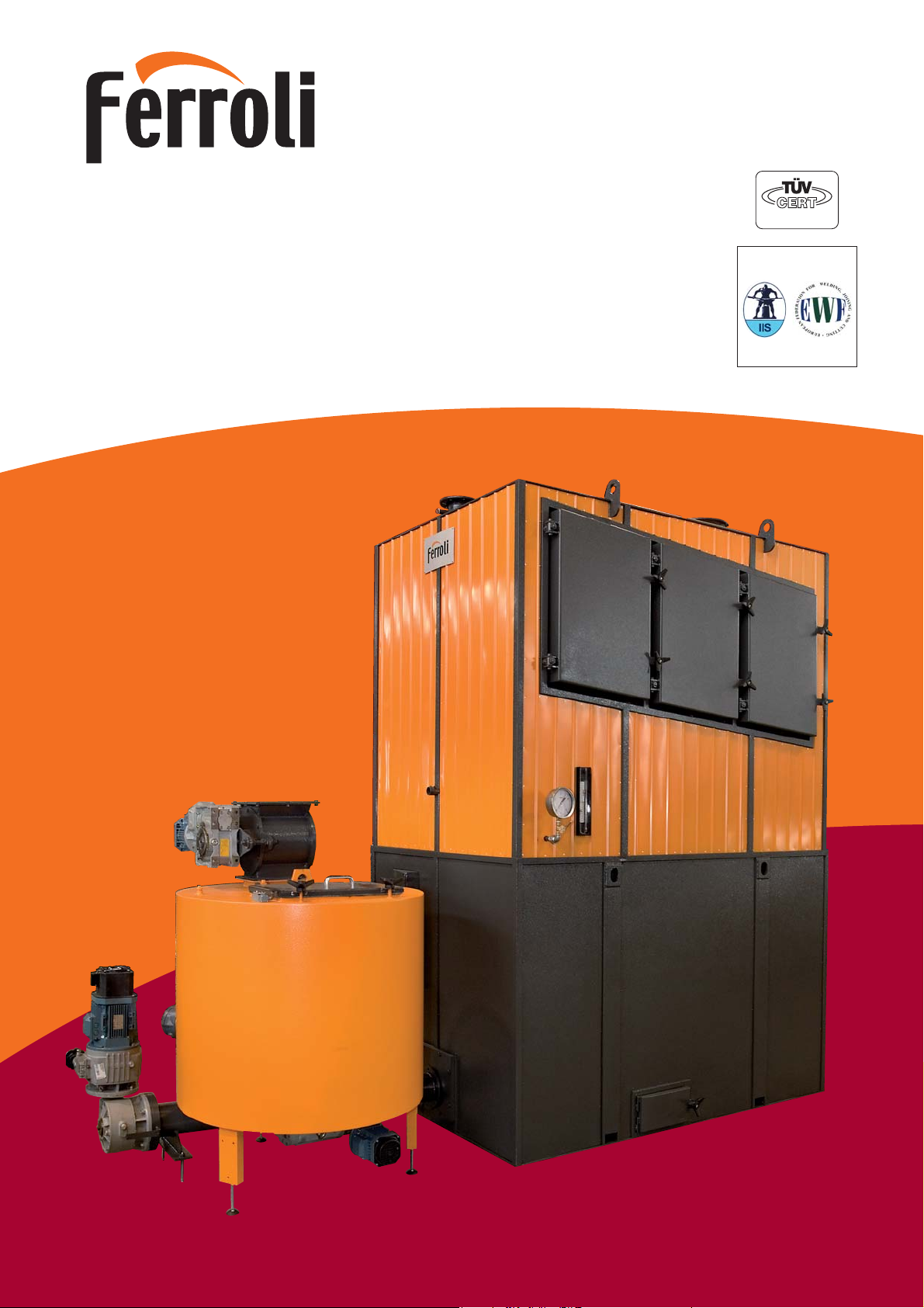
WOOD MATIC S
Caldaia per acqua calda a combustibili solidi
Solid fuel hot water boiler
DIVISIONE RISCALDAMENTO INDUSTRIALE • INDUSTRIAL HEATING DIVISION
DIN EN ISO 9001
UNI EN 729-2
Requisiti di qualità per la saldatura
certificati
Page 2

WOOD MATIC S
DESCRIZIONE GENERATORE
Il modello WOOD MATIC S è una caldaia mista a intercapedine e tubi
d'acqua, concepita appositamente per combustibili solidi, con struttura
tubiera conformata in funzione delle specifiche esigenze di pulibilità e
corretta combustione.
Le particolari soluzioni a livello di alimentazione e di griglia consentono
un apporto di combustibile dosato in continuo anche per materiale
grossolano e garantiscono il rispetto delle attuali norme in materia di
emissioni (D.P.C.M. 08/03/02 - D.L. 152/06).
I PRINCIPALI PUNTI QUALIFICANTI
POSSONO ESSERE COSI RIASSUNTI:
■ alimentazione a coclea di nostra concezione che nasce da un pro-
getto unico caldaia-focolare meccanico;
■ sottogriglia diviso in comparti stagni per una adduzione differenziata
dell’aria comburente;
■ camera di combustione molto ampia e completamente rivestita in
mattoni refrattari, dotata di volta di riverbero e percorso invertito dei
fumi per una ottimale essiccazione del combustibile umido;
■ combustione in due stadi, con gassificazione in griglia e rapporto
aria primaria/aria secondaria variabile in un ampio campo a seconda
del combustibile impiegato. Aria secondaria iniettata con sistema ad
alta turbolenza, indipendente;
■ il rivestimento refrattario, del tipo misto in gettata e in mattoni a
seconda delle diverse zone, è di elevato standard (AL2O3> 60%);
■ fascio tubiero e geometria del percorso fumi tali da garantire un
numero minimo di interventi di pulizia e accessibilità totale attraverso porte laterali;
■ il basamento che sostiene la caldaia alloggia la camera di combu-
stione ed é completamente rivestito di mattoni per una combustione
ad elevata temperatura ma è raffreddato a intercapedine d’acqua
per annullare il calore irraggiato dalle pareti esterne.
■ sistema termostatico per avanzamento automatico coclea e predi-
sposizione antincendio;
■ elevati rendimenti di combustione, normalmente superiori all’85%.
Tutto ciò viene realizzato in un unico blocco compatto, di comparativamente limitato ingombro e di rapida installazione.
La marcia di queste caldaie può essere del tipo ON-OFF, con possibilità
di tarare il sistema di combustione a potenze inferiori a quella massima,
sia con modulazione continua dal 50 al 100% della potenzialità bruciata.
DES
CRIPTION OF GENERATOR
The WOOD MATIC S is a mixed double-jacket and water-tube boiler
designed specifically for solid fuels. The tube nest is shaped in accordance with the specific requirements for ease of cleaning and correct
combustion.
The particular fuel feed and grate solutions enable a constant supply of
fuel to be delivered, even when using coarse material.
THE MAI
N ADVANTAGES OF THE BOILER ARE
SUMMED UP BELOW:
■ our specially conceived screw feed assembly, the result of a single
boiler-mechanical burner design;
■ undergrate divided into sealed compartments for differentiated com-
bustion air feed;
■ large and completely dry combustion chamber lined in refractory
bricks with rebound vault and reverse flue gas flow for optimum
drying of damp fuel;
■ two-stage combustion, with grate-level gasification and a wide
range of primary air/secondary air ratios according to the type of
fuel used. Secondary air is injected using an independent high
turbulence system;
■ high quality mixed cast and brick refractory cladding according to the
zone (AL2O3> 60%);
■ tube nest and geometry of flue gas route guarantees minimum clea-
ning operations and complete accessibility through side doors;
■ the base structure that supports the boiler houses the combustion
chamber, and is completely lined by special bricks for high-temperature combustion; it is cooled by water jacket to eliminate the heat radiated from the outer walls.
■ thermostatic system for automatic screw advance and optional fire
safety device;
■ high combustion efficiency, normally above 85%.
All this is incorporated in a single compact rapid to install unit with relatively small dimensions.
These boilers can be operated on an ON-OFF basis. The fuel system
can be calibrated for outputs lower than maximum, and also with continuous regulation from 100% down to 50% of heat input.
Page 3

WOOD MATIC S
ACCESSORI OPZIONALI
A seconda del tipo di combustibile e della potenzialità, possono essere
importanti alcuni accessori.
a) Bruciatore di accensione o pilota
Consente di operare in automatico la prima accensione del combustibile solido ed è indispensabile per materiali con elevata umidità.
Di tipo monoblocco ad una sola fiamma (~0,25 MW) può essere
alimentato da gasolio o gas metano.
Il suo inserimento in caldaia e arretramento allo spegnimento possono
essere automatizzati mediante sistema pneumatico. La logica elettrica
consente anche di avvalersi del suo supporto per abbattere ulteriormente il tenore di CO nei fumi nel caso di combustibili critici o umidi.
b) Potenza termica modulata in continuo
Permette di ridurre la potenzialità bruciata dal 100 fino al 50%, riducendo al minimo gli spegnimenti della caldaia. La sonda di temperatura dell’acqua di andata agisce sul regolatore a logica
programmabile che modifica la velocità della coclea di alimentazione
e le portate d’aria comburente mediante inverter che comandano i
motori relativi.
c) Regolatore di tiraggio
Mantiene costante, al valore impostato, il tiraggio in camera di combustione. Consta di strumento rilevatore e farfalla motorizzata sul
condotto di by-pass della batteria multiciclonica oppure inverter
sull’aspiratore fumi. Ha un ruolo importante nel contenimento delle
emissioni di polveri.
d) Analizzatore con controllo in continuo
Lettura su display di: CO - O2- temperatura fumi camino (l’analizzatore O2viene di solito integrato con un sistema di regolazione automatico dell’aria comburente). È possibile il trasferimento dati su PC
con memoria.
e) Scala e passerella per l’accesso alle porte di pulizia laterali dal
fascio tubiero.
f) Kit di bocche aspiranti per la corretta pulizia del fascio tubiero a
mezzo di aspiratore industriale (quest’ultimo escluso).
OPTIO
NAL ACCESSORIES
Depending on the type of fuel and rating of the boiler, a number of important accessories are available.
a) Ignition or pilot burner
This enables the solid fuel to be ignited automatically at start-up and
is indispensable with particularly damp fuel. This single flame monobloc device (~0.25 MW) can be fed by diesel or methane gas.
A pneumatic system can be used to automatically control its insertion
into the boiler and return on shut-down.
The electrical logic also allows this to be used for a further reduction
in the CO content of the flue gas when using critical or damp fuel.
b) Continuous heat output modulation
Allows the heat input to be reduced continuously from 100% to
50%, minimising the number of shut-downs. A programmable controller connected to the water outlet temperature probe varies the rotation speeds respectively of the fuel feed screw and the combustion
air fans using inverters that drive the corresponding motors.
c) Draught regulator
This keeps the draught in the combustion chamber constant at a
set level. It consists in a sensor device that controls a motorised
throttle on the multi-cyclone assembly by-pass duct or the inverter-driven drought fan. It has an important role to play in reducing dust emissions.
d) Constant control analyser
Display of CO - O2, Display of CO - O2, flue gas temperature (the
O2analyser is usually integrated with an automatic combustion air
control system).
The data can be transferred to a PC and saved.
e) Ladder and walkway for accessing the side cleanout doors from
the tube bundle.
f) Vacuum cleaner attachment kit for the correct cleaning of the
tube bundle using an industrial vacuum cleaner (the latter is not supplied).
Page 4

WOOD MATIC S
Legenda
1 corpo caldaia 2 basamento 3 tramoggia
4 focolare meccanico
a1 mandata a2 ritorno a3 attacco camino
a4 caricamento tramoggia a5 attacco bruciatore pilota
Key
1 boiler body 2 base 3 hopper
4 mechanical stocker
a1 flow a2 return a3 flue connection a4 hopper loading
a5 pilot burner attachment
CALDAIA A GRIGLIA FISSA ACQUA CALDA: MAX. 100°C
FIXED GRID BOILER FOR HOT WATER PRODUCTION: MAX. 100°C
PRESSIONE ESERCIZIO: 2 bar
WORKING PRESSURE: 2 bar
WOOD MATIC S 150 250 400 600 800 1000 1200 1500 2000
Potenzialità generatore / Generator rating kW 174 290 465 700 930 1163 1395 1768 2326
Potenzialità focolare / Heat input kW 205 341 547 823 1094 1368 1641 2080 2736
Contenuto d’acqua / Water content dm
3
656 864 1092 1292 1691 1786 1904 2698 2755
Superficie di scambio (totale) / Heat exchange surface (total) m
2
15,6 20,9 29,5 43,9 57,8 68,6 79,4 102,7 128,3
Volume camera combustione / Combustione chamber cap. m30,943 1,214 1,463 2,263 2,830 3,048 3,910 4,539 6,956
Δp lato fumi / Δp flue gas side mbar 0,8 1,2 1,6 2,0 2,7 3,2 3,3 3,5 4,9
Δp lato acqua / Δp water side mbar 110 150 180 250 300 350 400 400 480
Peso caldaia / Weight of the boiler kg 1330 1710 2180 2470 3280 3900 4180 4940 5890
Peso basamento / Weight of the bed kg 2430 3040 3390 4130 4970 5230 6080 6480 6840
Peso tramoggia / Weight of the hopper kg 210 210 210 210 340 340 340 340 340
Peso alimentatore / Feeder weight kg 130 130 130 210 250 250 360 360 410
a1-a2 DN 65 80 80 100 125 125 125 125 150
a3 mm 200 250 250 300 350 350 400 400 500
a4 mm 270x170 270x170 270x170 270x170 270x170 270x170 270x170 270x170 270x170
a5
lung. boccaglio / draught tube length mm 250-300 250-300 250-300 250-300 280-350 280-350 280-350 280-350 280-350
Ø boccaglio max. / draught tube max. dia. mm 130 130 130 130 155 155 155 155 155
WOOD MATIC S A B C D E F G H L M N P
150 1271 1260 1583 790 725 800 1370 3538 4798 2960 900 1267
250 1400 1260 1803 790 745 800 1370 3767 5038 2960 900 1367
400 153 0 1310 1918 79 0 745 8 00 13 70 3917 515 3 3 010 9 00 138 7
600 1659 1520 2253 820 905 800 1353 4046 5578 3220 900 1387
800 1828 1520 2473 970 900 1000 1360 4412 6243 3220 1200 1584
1000 1937 1600 2473 970 900 1000 1360 4521 6243 3300 1200 1584
120 0 2007 1600 2808 980 900 1000 1360 4644 6588 3300 1200 1637
150 0 2204 1730 2900 980 900 1000 1360 4841 6680 3430 1200 1637
2000 2420 1730 3500 990 975 1000 1388 5172 7365 3430 1200 1752
Page 5

WOOD MATIC S
CORPO CALDAIA / BOILER BODY
1.1 CAMERA A CALORE RADIANTE / RADIANT HEAT CHAMBER
1.2 VOLTO DI RINVIO FUMI / FLUE GAS REBOUND VAULT
1.3 PORTA DI PULIZIA FASCIO TUBIERO / TUBE NEST CLEANING DOOR
1.4 PORTA DI PULIZIA VOLTINO / FURNACE ARCH CLEANOUT DOOR
1.5 PORTINA ANTISCOPPIO / EXPLOSION-PROOF DOOR
1.6 FASCIO TUBIERO / TUBE NEST
1.7 SETTI DEFLETTORI FUMI / FLUE GAS DEFLECTOR BAFFLES
1.8 CONDOTTO USCITA FUMI / FLUE
1.9 MANOMETRO CON RUBINETTO DI PROVA / PRESSURE GAUGE WITH TEST COCK
1.10 DEPRIMOMETRO / VACUOMETER
1.11 CONTROLLO TEMPERATURA DI COMBUSTIONE / COMBUSTION TEMPERATURE
CONTROL
ACCESSORI OPZIONALI / OPTIONAL ACCESSORIES
1.12 REGOLATORE DI TIRAGGIO CON INVERTER SU ASP. FUMI / DRAUGHT REGULATOR
2.10 BRUCIATORE PILOTA DI ACCENSIONE / PILOT BURNER
2.11 MODULAZIONE IN CONTINUO DELLA PORTATA COMBUSTIBILE E DELL’ARIA
COMBURENTE / CONTINUOUS MODULATION OF THE FUEL AND COMBUSTION
AIR FLOW-RATE
BASAMENTO / BED
2.1 VENTILATORE ARIA COMB. PRIMARIA / PRIMARY COMBUSTION AIR FAN
2.2 VENTILATORE ARIA COMB. SECONDARIA
SECONDARY COMBUSTION AIR FAN
2.3 PORTA PULIZIA CAMERA COMBUSTIONE
COMBUSTION CHAMBER CLEANING DOOR
2.4 PORTA PULIZIA SOTTOGRIGLIA INTERNA
INTERNAL UNDERGRATE CLEANING DOOR
2.5 PORTA PULIZIA SOTTOGRIGLIA ESTERNA
EXTERNAL UNDERGRATE CLEANING DOOR
2.6 GRIGLIA INTERNA / INTERNAL GRATE
2.7 GRIGLIA ESTERNA / EXTERNAL GRATE
2.8 UGELLI ARIA SECONDARIA / SECONDARY AIR NOZZLES
2.9 SPIA CONTROLLO COMBUSTIONE / COMBUSTION INSPECTION OPENING
FOCOLARE MECCANICO / MECHANICAL FURNACE
3.1 MOTOVARIATORE / ADJUSTABLE SPEED MOTOR GEAR
3.2 ALIMENTATORE A COCLEA / FEED SCREW
3.3 TRAMOGGIA CON CONTROLLO DI LIVELLO / HOPPER WITH LEVEL CONTROL
3.4 RASCHIATORE MOTORIZZATO / MOTORISED SCRAPER
3.5 SICUREZZA ANTIRITORNO DI FIAMMA / ANTI BACK-FIRING SYSTEM
WOOD MATIC S 150 250 400 600 800 1000 1200 1500 2000
Ventilatore aria comburente primaria / Primary combustion air fan kW 0,25 0,25 0,25 0,55 0,55 1,1 1,1 2,2 2,2
Ventilatore aria comburente secondaria / Secondary combustion air fan kW 0,55 0,55 0,55 0,75 0,75 1,1 1,1 2,2 2,2
Raschiatore tramoggia / Hopper scraper kW 0,25 0,25 0,25 0,25 0,37 0,37 0,37 0,37 0,37
Motovariatore focolare meccanico / Mechanical furnace adjustable speed motor gear kW 2,2 2,2 2,2 2,2 2,2 2,2 3 3 5,5
Potenza elettrica totale / Total electrical power kW 3,25 3,25 3,25 3,75 3,87 4,77 5,57 7,77 10,27
POTENZE ELETTRICHE INSTALLATE / ELECTRICAL OUTPUTS INSTALLED
Page 6
WOOD MATIC S
COMBUSTIBILI COMPATIBILI
TIPOLOGIA
■ Rifiuti della prima e seconda lavorazione del legno e del sughero
non trattati.
■ Biomasse (Scarti vegetali di attività agricole, forestali, di prima lavo-
razione dei prodotti agroalimentari, sanse esauste, vinaccioli, farina
di vinaccioli, residui di frutta, buccette e altri residui vegetali).
■ Pellets di legno.
GRANULO
METRIA
■ - Nocciolo: 0 ÷ 30 mm
- Filamento: 0 ÷ 60 mm
come tal quale o derivante dai diversi trattamenti meccanici
(trucioli, segatura, legno sminuzzato, pellets ecc.)
DENSITÀ APPARENTE:
■ Min. 80 kg/m
3
■ Max. 500 kg/m
3
UMIDITÀ MAX.: 80% sul secco (44% sul lordo), oltre il 30% occorre
declassare la caldaia.
COMPATIBLE FUELS
TYPES
■ Waste from primary and secondary processes for working
untreated wood and cork.
■ Biomass (plant waste from agricultural and forestry activities and
from the first processing phase of agricultural and food products,
depleted residues, grape seed, grape seed flour, fruit residues,
peels and other plant residues).
■ Wood pellets.
GRAI
N SIZE
■ - Pieces: 0 ÷ 30 mm
- Filament: 0 ÷ 60 mm
as is, or deriving from various mechanical processes
(shavings, sawdust, shreddings, pellets etc.)
APPARENT DENSITY:
■ Min. 80 kg/m
3
■ Max. 500 kg/m
3
MAX. M
OISTU
RE:
80% dry weight (44% of total weight), over 30%,
the boiler must be downgraded.
20 30 40 50 60 70 80
20 25 30 35 40 45
1,00
0,92
0,85
0,78
0,72
0,66
0,60
0,56
K
% UMIDITÀ
BASE SECCO
DRY BASIS
HUMIDITY PERCENTAGE
% UMIDITÀ
BASE UMIDO
GROSS BASIS
HUMIDITY PERCENTAGE
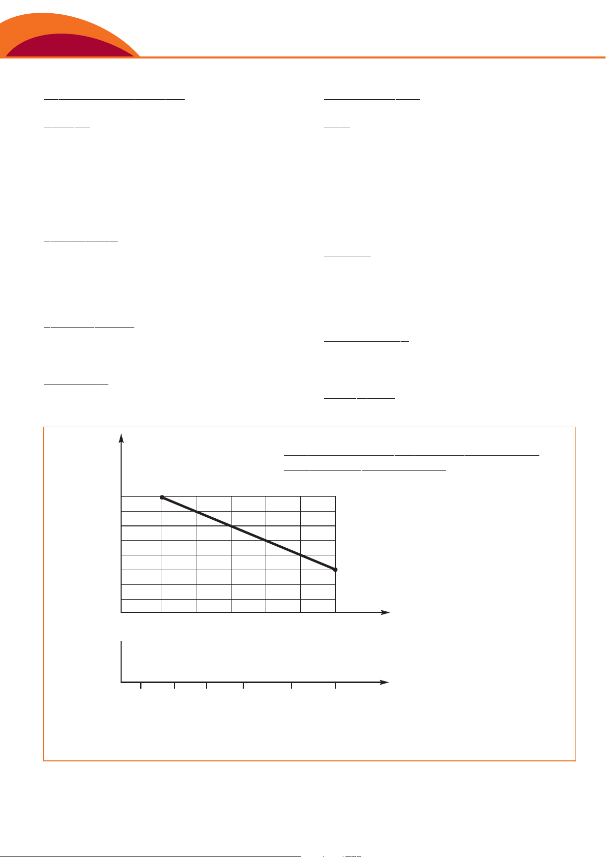
K = FATTORE DI MOLTIPLICAZIONE PER DECLASSAMENTO
K = MULTIPLICATION FACTOR FOR DOWNGRADING
DIAGRAMMA DI DECLASSAMENTO DELLA POTENZIALITÀ
OUTPUT DOWNGRADING DIAGRAM
Il diagramma illustra come, a partire dal 30% di umidità nel combustibile, sia necessario aumentare sia la superficie di scambio che la superficie
di griglia e ciò si traduce in pratica in un declassamento della caldaia.
The diagram illustrates how starting from 30% moisture in the fuel, the
surface of the grate and the exchange surface must be increased, which in practice means the downgrading of the boiler.
Page 7

WOOD MATIC S
GARANZIE SUL PROCESSO DI COMBUSTIONE
E SULLE E
M
ISSIONI AL CAMINO
In riferimento alle norme citate e nei limiti dei combustibili descritti, siamo
in grado di garantire i seguenti valori (all.to III° del D.P.C.M. 08/03/02):
COMBUSTION PROCESS
AND FL
U
E EMISSION GUARANTEES
In reference to the standards and within the limits of the fuels listed,
we are able to guarantee the following values:
Grandezza di misura Mg/Nm
3
Polveri totali
10 0
(1)
Dust
Carbonio organico totale (C.O.T.)
—
T.O.C. - Total organic carbon
Monossido di carbonio (CO)
350
(2)
Carbon monoxide
Ossidi di azoto (espressi come NO2)
500
Nitrogen oxides
Ossidi di zolfo (espressi come SO2)
200
Sulphur oxides
N.B. - I limiti riportati sono riferiti ad un tenore di O2di riferimento dell’11%.
(1)
Ottenibile con impianto filtrazione e costituito da solo multiciclone, purchè
di fornitura Ferroli.
(2)
Per umidità superiori a 30% base secco, consultare il nostro Ufficio Tecnico.
N.B. - The limits shown here refer to an oxygen level of 11%.
(1)
The value can be achieved using a filtering system made up of a multiple
centrifugal dust separator only, as long as this is supplied by Ferroli.
(2)
For moisture above 30% on dry weight, contact our Technical Department.
Page 8

Ferroli spa ¬ 37047 San Bonifacio (Verona) Italy ¬ Via Ritonda 78/A
Industrial Boilers Division ¬ 37047 Villanova di San Bonifacio (Verona) Italy ¬ Via Marco Polo, 15
Italian Sales Dept. ¬ tel. +39 045 6139915/914 ¬ fax +39 045 6103490
Export Sales Dept. ¬ tel. +39 045 6139928 ¬ fax +39 045 6139926
Web site: www.ferroli-industrialboilers.com
COD. 89FM4011 - 01.2007
Nell’ottica della ricerca del miglioramento continuo della propria gamma produttiva, al fine di aumentare il livello di soddisfazione del Cliente,
l’Azienda precisa che le caratteristiche estetiche e/o dimensionali, i dati tecnici e gli accessori possono essere soggetti a variazione.
In accordance with the constant efforts to improve its range of products and thus raise the level of customer satisfaction,
the Company stresses that the appearance and/or size, technical specifications and accessories may be subject to variation.
SISTEMA TIPO DI IMPIANTO / TYPICAL SYSTEM DIAGRAM
1 TRAMOGGIA CON CONTROLLO DI LIVELLO / HOPPER WITH LEVEL CONTROL
2 ALIMENTATORE A FOCOLARE MECCANICO / MECHANICAL FURNACE FEEDER
3 VALVOLA STELLARE / ROTARY VALVE
4 BRUCIATORE PILOTA / PILOT BURNER
5 STRUMENTO DI MISURA TEMPERATURA ACQUA E MODULAZIONE PORTATA
COMBUSTIBILE / INSTRUMENT FOR MEASURING WATER TEMPERATURE
AND FUEL FLOW-RATE MODULATION
6 CORPO CALDAIA / BOILER BODY
7 BASAMENTO / BED
8 MULTICICLONE TERMICAMENTE ISOLATO / THERMALLY INSULATED MULTIPLE
CENTRIFUGAL DUST SEPARATOR
9 ASPIRATORE FUMI / FLUE GAS EXHAUST
10 CONDOTTI FUMI TERMICAMENTE ISOLATI / THERMALLY INSULATED FLUES
11 PUNTI DI PROVA INTERMEDI SUI FUMI / INTERMEDIATE FLUE GAS TEST POINTS
12 CAMINO AUTOPORTANTE TERMICAMENTE ISOLATO
THERMALLY INSULATED SELF-SUPPORTING STACK
13 PUNTI DI PROVA FUMI AL CAMINO / FLUE GAS TEST POINTS IN THE STACK
14 SCALA E PASSERELLA DI ACCESSO AGLI ATTACCHI DI PROVA FUMI
ACCESS LADDER AND GANGWAY FOR FLUE GAS TEST POINTS
15 QUADRO ELETTRICO GENERALE / MAIN ELECTRICAL PANEL
16 VENTILATORE ARIA COMBURENTE PRIMARIA / PRIMARY COMBUSTION AIR FAN
17 VENTILATORE ARIA COMBURENTE SECONDARIA
SECUNDARY COMBUSTION AIR FAN
 Loading...