

Page 1

RMP
AIR-WATER CHILLERS AND HEAT PUMPS
FOR INDOOR INSTALLATION
TECHNICAL MANUAL
R
E
F
R
I
G
E
R
A
N
T
G
A
S
E
C
O
-
F
R
I
E
N
D
L
Y
Page 2

2
The manufacturer declines all the responsabilities regarding inaccuracies contained in this manual, if due to printing or typing mi-
stakes. The manufacturer reserves the right to apply changes and improvements to the products at any time without notice.
Page 3

3
TABLE OF CONTENTS
GENERAL FEATURES 5
Unit description . . . . . . . . . . . . . . . . . . . . . . . . . . . . . . . . . . . . . . . . . . . . . . . . . . . . . . . . . . . . . . . . . . . . . . . . . . . . . . 5
Unit identification code . . . . . . . . . . . . . . . . . . . . . . . . . . . . . . . . . . . . . . . . . . . . . . . . . . . . . . . . . . . . . . . . . . . . . . . . 5
Description of components . . . . . . . . . . . . . . . . . . . . . . . . . . . . . . . . . . . . . . . . . . . . . . . . . . . . . . . . . . . . . . . . . . . . . 6
Control system . . . . . . . . . . . . . . . . . . . . . . . . . . . . . . . . . . . . . . . . . . . . . . . . . . . . . . . . . . . . . . . . . . . . . . . . . . . . . . 7
Versions . . . . . . . . . . . . . . . . . . . . . . . . . . . . . . . . . . . . . . . . . . . . . . . . . . . . . . . . . . . . . . . . . . . . . . . . . . . . . . . . . . . 7
Options . . . . . . . . . . . . . . . . . . . . . . . . . . . . . . . . . . . . . . . . . . . . . . . . . . . . . . . . . . . . . . . . . . . . . . . . . . . . . . . . . . . . 8
Accessories . . . . . . . . . . . . . . . . . . . . . . . . . . . . . . . . . . . . . . . . . . . . . . . . . . . . . . . . . . . . . . . . . . . . . . . . . . . . . . . . 9
TECHNICAL DATA AND PERFORMANCES 10
Technical data. . . . . . . . . . . . . . . . . . . . . . . . . . . . . . . . . . . . . . . . . . . . . . . . . . . . . . . . . . . . . . . . . . . . . . . . . . . . . . . 10
NOMINAL performances - Base setting up (VB) - Standard plants . . . . . . . . . . . . . . . . . . . . . . . . . . . . . . . . . . . . . . 11
NOMINAL performances - Base setting up (VB) - Radiant plants . . . . . . . . . . . . . . . . . . . . . . . . . . . . . . . . . . . . . . . 12
NOMINAL performances - Low noise setting up (AS) - Standard plants . . . . . . . . . . . . . . . . . . . . . . . . . . . . . . . . . . 13
NOMINAL performances - Low noise setting up (AS) - Radiant plants . . . . . . . . . . . . . . . . . . . . . . . . . . . . . . . . . . . 14
COOLING performances . . . . . . . . . . . . . . . . . . . . . . . . . . . . . . . . . . . . . . . . . . . . . . . . . . . . . . . . . . . . . . . . . . . . . . 15
HEATING performances. . . . . . . . . . . . . . . . . . . . . . . . . . . . . . . . . . . . . . . . . . . . . . . . . . . . . . . . . . . . . . . . . . . . . . . 16
Plant side hydraulic performances . . . . . . . . . . . . . . . . . . . . . . . . . . . . . . . . . . . . . . . . . . . . . . . . . . . . . . . . . . . . . . . 17
Source side aeraulic performances . . . . . . . . . . . . . . . . . . . . . . . . . . . . . . . . . . . . . . . . . . . . . . . . . . . . . . . . . . . . . . 19
Operating limits. . . . . . . . . . . . . . . . . . . . . . . . . . . . . . . . . . . . . . . . . . . . . . . . . . . . . . . . . . . . . . . . . . . . . . . . . . . . . . 20
Electrical data . . . . . . . . . . . . . . . . . . . . . . . . . . . . . . . . . . . . . . . . . . . . . . . . . . . . . . . . . . . . . . . . . . . . . . . . . . . . . . . 21
Noise levels . . . . . . . . . . . . . . . . . . . . . . . . . . . . . . . . . . . . . . . . . . . . . . . . . . . . . . . . . . . . . . . . . . . . . . . . . . . . . . . . 21
Weights. . . . . . . . . . . . . . . . . . . . . . . . . . . . . . . . . . . . . . . . . . . . . . . . . . . . . . . . . . . . . . . . . . . . . . . . . . . . . . . . . . . . 22
Overall dimensions . . . . . . . . . . . . . . . . . . . . . . . . . . . . . . . . . . . . . . . . . . . . . . . . . . . . . . . . . . . . . . . . . . . . . . . . . . . 23
Minimum operating area . . . . . . . . . . . . . . . . . . . . . . . . . . . . . . . . . . . . . . . . . . . . . . . . . . . . . . . . . . . . . . . . . . . . . . . 23
Page 4

4
Page 5

5
IP 261 VB AB 0M5
GENERAL FEATURES
Unit description
This series of air-water chillers and heat pumps satises the cooling and heating requirements of residential plants of small and
medium size.
All the units are suitable for indoor installation and can be applied to fan coil plants, radiant oor plants and high efciency
radiators plants.
The refrigerant circuit, contained in a compartment protected
from the air ow to simplify the maintenance operations, is
equipped with scroll compressor mounted on damper supports,
brazed plate heat exchanger, thermostatic expansion valve, reverse cycle valve, centrifugal fans (plug fan), nned coil made of
copper pipes and aluminium louvered ns. The circuit is protected by high and low pressure switches and differential pressure
switch on the plate heat exchanger.
The plate heat exchanger and all the hydraulic pipes are thermally insulated in order to avoid condensate generation and to
reduce thermal losses.
All the units are equipped with variable speed fans control that
allows the units to operate with low outdoor temperatures in cooling and high outdoor temperature in heating and permits to
reduce noise emissions in such operating conditions.
The low noise acoustic setting up (AS) is obtained, starting from
the base setting up (AB), reducing the rotational speed of the
fans and mounting sound jackets on the compressors.
All the units are supplied with an outdoor temperature sensor, already installed on the unit, in order to realize the climatic control.
All the units are provided with a phase presence and correct
sequence controller device.
All the units are accurately built and individually tested in the
factory. Only electric and hydraulic connections are required for
installation.
Unit identification code
The codes that identify the units and the meaning of the letters used are described below.
Unit type
IR - Unit suitable for hydronic plant installation operating as chiller
IP - Unit suitable for hydronic plant installation operating as reversible heat
pump
BR - Unit suitable for hydronic plant installation with brine solutions operating
as chiller
BP - Unit suitable for hydronic plant installation with brine solutions operating
as reversible heat pump
Power supply
5 - 400 V - 3N - 50 Hz
Operating range
M - Medium temperature.
The unit is suitable to be installed in temperate climates.
Refrigerant type
0 - R410A
Acoustic setting up
AB - Base setting up
AS - Low noise setting up
Unit version
VB - Base version
VP - Pump version
VA - Tank version
N° compressors
Unit model
RMP
Page 6

6
GENERAL FEATURES
Description of components
External structure. Basement, supporting structure and lateral
panels are made of galvanized and painted sheet-steel (colour
RAL 7035) to guarantee good resistance to atmospheric agents.
Accessibility to internal parts is possible removing the frontal
panel. For extraordinary manteinances also the rear panel can
be removed.
Refrigerant circuit. It is contained inside a compartment
separated from the air flow to simplify maintenance and control
operations.
The hermetic scroll compressor (1) is mounted on damper
supports and is protected against overtemperatures and
overcurrents. It is equipped with an electrcal heater, that is
activated when the compressor turns off, to keep the compressor
crankcase oil temperature high enough to prevent migration of
the refrigerant during winter stops and to evaporate any liquid
present in the crankcase, in order to prevent possible liquid
rushes on starting (only heat pump models).
The plant side heat exchanger (2) is a brazed stainless steel
plate heat exchanger, properly insulated to avoid condensate
generation and to minimize thermal losses, and protected by a
differential pressure switch that detects whatever water flow lack.
It is moreover protected against freeze danger by an antifreeze
electrical heater.
The source side heat exchanger (3) is a finned coil realized with
grooved copper pipes and aluminium fins with notched profile to
increase the heat exchange coefficient. A tray is obtained in the
basement to collect the condensate generated in heating mode.
The expansion device (4), a thermostatic expansion valve with
external equalizer, allows the unit to adjust itself to the different
operating conditions keeping steady the set superheating.
The refrigerant circuit of each unit contains moreover solid
core hermetic filter dryer (5) to restrain impurity and moisture
residuals that could be present in the circuit, high and low
pressure switches in order to assure the compressor to
operate inside the permitted limits, 4 way reverse cycle valve
(6) to allow operating mode change reversing the refrigerant flow
(only heat pump models), liquid receiver (7) to compensate the
different refrigerant charge required in heating and in cooling
mode (only heat pump models) and pressure connections
SAE 5/16” - UNF 1/2” - 20 equipped with pin, gasket and
blind nut, as required for the use of R410A refrigerant (they
allow the complete check of the refrigerant circuit: compressor
inlet pressure, compressor outlet pressure and thermostatic
expansion valve upstream pressure).
The fans (8) are plug fan type fans equipped with EC direct
current motor and embedded inverter. The fans rotational speed
is modulated continuosly to control the condensation pressure
(in cooling) and the evaporation pressure (in heating) in order to
optimize the operating conditions of the unit and to reduce noise
emissions. The maximum rotational speed can be modified by
parameter in order to set the available static head of the fan to
the plant requirements.
Hydraulic circuit. All the pipes are thermally insulated to avoid
condensate generation and minimize thermal losses. The circuit
can be equipped with different kind of circulation pump (option).
In that case the circuit is also equipped with expansion vessel
and air vents. It is also possible to integrate inside the unit a buffer
tank arranged as buffer on the flow towards the plant (option). In
that case the circuit is equipped not only with expansion vessel
and air vents, but also with safety valve, automatic air vent and
drain cock.
Electrical panel. It contains all the power, control and security
components necessary to guarantee the unit to work properly.
The unit is managed by a microprocessor controller to which all
the electrical loads and the control devices are connected. The
user interface, placed on the frontal panel, allows to view and to
modify, if necessary, all the parameters of the unit.
All the units are supplied with an outdoor temperature sensor,
already installed on the unit, in order to realize the climatic
control.
3
7
2
6
4
5
1
8
3
7
2
6
4
5
1
8
Page 7

7
GENERAL FEATURES
Control system
The unit is managed by a microprocessor controller to which,
through a wiring board, all the electrical loads and the control
devices are connected. The user interface is realized by a
display and four buttons that allow to view and, if necessary,
modify all the operating parameters of the unit. It's available, as
an accessory, a remote control that reports all the functionalities
of the user interface placed on the unit.
The main functions available are :
- water temperature management (through set point
adjustment)
- adaptive function
- climatic control in heating and in cooling mode (automatic set
point adjustment according to outdoor air temperature)
- dynamic defrost cycle management according to outdoor air
temperature
- alarm memory management and diagnostic
- fans management by means of continuous rotational speed
control
- pump management
- integrative electrical heaters management in heating mode
(2 step logic)
- compressor and pump operating hours recording
- serial communication through Modbus protocol
- remote stand by
- remote cooling-heating
- general alarm digital output
Versions
Each model can be supplied in three different versions to satisfy the application requirements of the plants. The unit is always
supplied assembled, wired and factory tested.
The version is automatically identified by the option "Storing and pumping module" selected.
Base Version - VB
The unit does not contain neither
circulating pump nor tank. Therefore
a proper water flow through the plate
heat exchanger must be guaranteed to
prevent internal safety devices activation.
In any case the pump, if properly sized,
can be connected to the electrical panel
of the unit and managed by the controller
of the unit.
Pump Version - VP
The unit contains a circulating pump, air
vents, expansion vessel and drain cock.
Tank Version - VA
The unit contains a tank (arranged as
buffer on the flow towards the plant),
safety valve, circulating pump, air vents,
expansion vessel and drain cock.
The tank is also arranged for the
installation of antifreeze or integrative
electrical heaters.
°C
1
2
1 2
mode
disp
Page 8

8
GENERAL FEATURES
Options
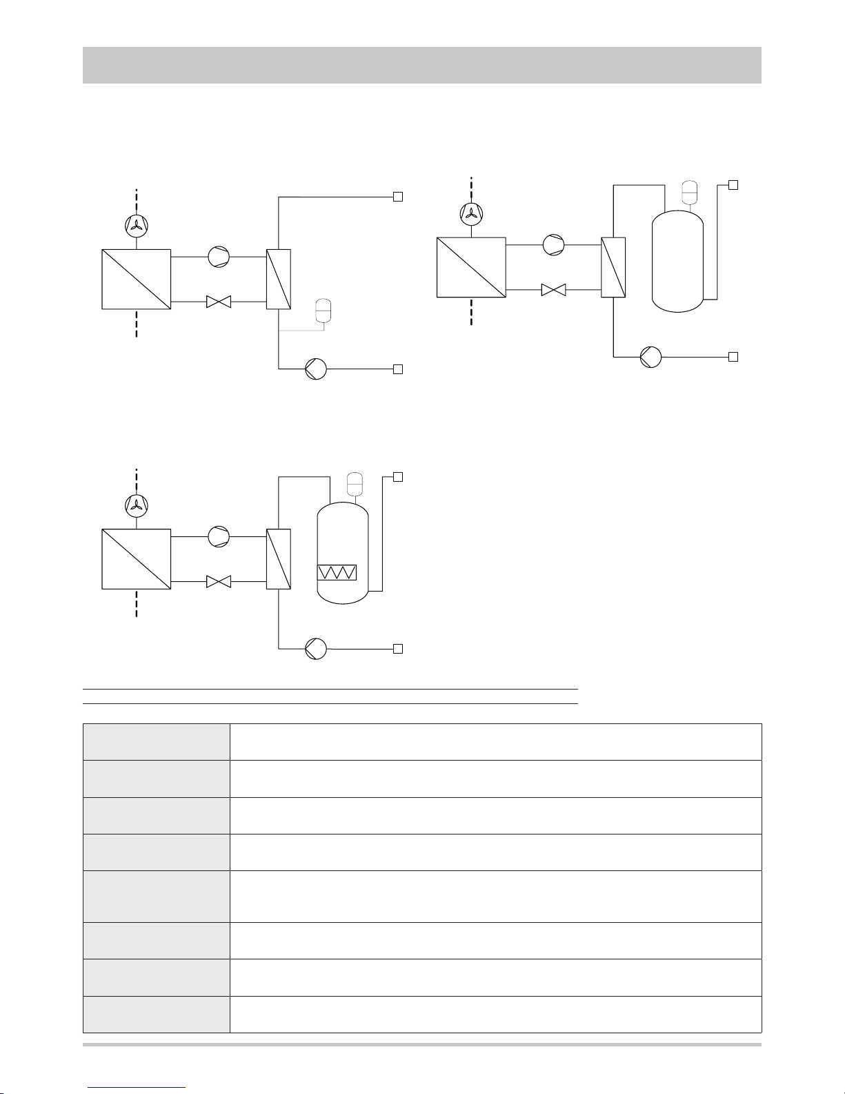
Storing
and pumping
module
Standard pump Allows the circulation of the water on the plant side.
High head pump
Allows the circulation of the water on the plant side and guarantees a higher available static head, suitable for high pressure drop plants.
Modulating pump
Allows the circulation of the water on the plant side with the possibility to set the
rotational speed of the pump in order to get the requested flow rate without the
necessity to install other setting devices.
Tank and
standard pump
Allows the circulation of the water on the plant side.
The thermal inertia of the buffer tank allows to reduce the number of compressor
starts and to guarantee a more stable flow temperature.
Tank and
high head pump
Allows the circulation of the water on the plant side and guarantees a higher available static head, suitable for high pressure drop plants.
The thermal inertia of the buffer tank allows to reduce the number of compressor
starts and to guarantee a more stable flow temperature.
Tank and
modulating pump
Allows the circulation of the water on the plant side with the possibility to set the
rotational speed of the pump in order to get the requested flow rate without the
necessity to install other setting devices.
The thermal inertia of the buffer tank allows to reduce the number of compressor
starts and to guarantee a more stable flow temperature.
Integrative
electrical
heaters
Standard in the tank
Integrate or replace the heating power supplied by the heat pump and are managed
by the unit controller with a 2 step logic.
They are also activated as antifreeze electrical heaters.
Available only for the VA version.
Soft starter Reduces the compressor start current.
Compressor power factor correction
Allows to reduce the phase shift between the absorbed current and the power supply voltage keeping it above the value of 0,9.
Electrical loads
protection
Fuses Allows to protect the electrical loads with fuses.
Thermal magnetic
circuit breakers
Allows to protect the electrical loads with thermal magnetic circuit breakers simplifying the maintenance operations.
Chiller (IR) without options (VB) Heat pump (IP) without options (VB)
Page 9
9
GENERAL FEATURES
Rubber vibration dampers
Allow to reduce the transmission to the unit support plane of the mechanical vibrations generated by the compressor
and by the fans in their normal operating mode.
Coil protection grille Protects the external surface of the finned coil..
Tank antifreeze
electrical heater
Activated together with the antifreeze electrical heater of the plate heat exchanger, it has the task to keep the water
in the buffer tank at a temperature high enough to avoid ice generation during winter.
Remote control
It is suitable for wall mounting and reports all the control and visualization functions available on the user interface
placed on the unit. It therefore allows the complete remote control of the unit.
Modbus serial interface
on RS485
It allows to communicate with the unit controller and to view the operating conditions of the unit through Modbus
communication protocol. The RS485 serial line ensures the signal quality up to distances of about 1200 meters (that
can be extended by means of proper repeaters).
Programmer clock
It allows the unit to be turned on and off according to a set program, through the digital input available on the unit
wiring board (remote stand by).
Phase sequence and
voltage controller
It checks not only the presence and correct order of the power supply phases but also the voltage level on each
phase and avoid the unit to operate with voltage levels outside the permitted limits.
Water flow switch
Allows to detect the water flow lack through the plate heat exchanger and operates as an integration of the protecion
offered by the differential pressure switch (standard).
Accessories
Option "Storing and pumping module"
Standard, high head or modulating pump
(VP version)
Option "Integrative electrical heaters"
Tank and standard, high head or modulating pump
(VA version)
Standard in the tank
(only for VA version)
Page 10
10
TECHNICAL DATA AND PERFORMANCES
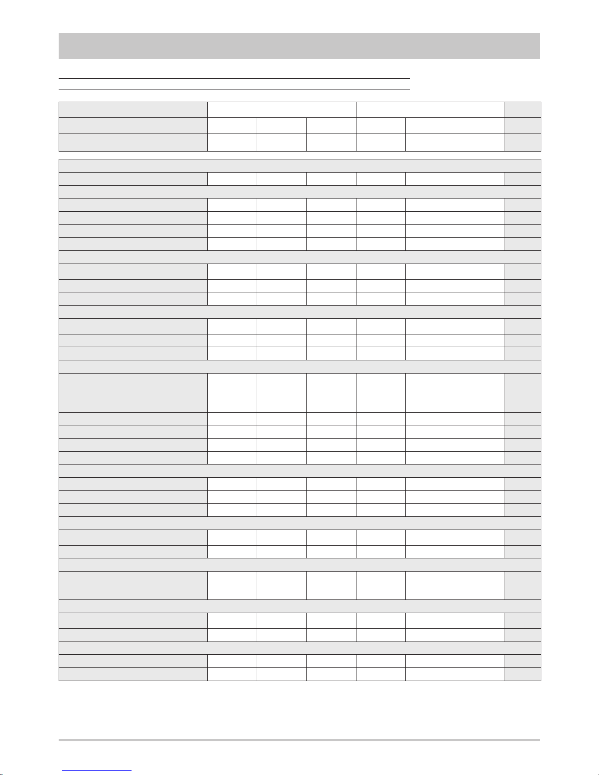
Frame
1 2
Model
191 221 261 301 351 401
U.M.
Power supply
400 - 3N - 50 400 - 3N - 50 400 - 3N - 50 400 - 3N - 50 400 - 3N - 50 400 - 3N - 50 V-ph-Hz
Technical data
Refrigerant
Type
R410A R410A R410A R410A R410A R410A -
Compressor
Type
scroll scroll scroll scroll scroll scroll -
Quantity
1 1 1 1 1 1 n°
Power steps
0 - 100 0 - 100 0 - 100 0 - 100 0 - 100 0 - 100 %
Oil charge
2,51 3,25 3,25 3,25 3,25 3,25 kg
Plant side heat exchanger
Type
stainless steel
brazed plates
stainless steel
brazed plates
stainless steel
brazed plates
stainless steel
brazed plates
stainless steel
brazed plates
stainless steel
brazed plates
-
Quantity
1 1 1 1 1 1 n°
Water volume
1,90 1,90 2,56 2,56 3,33 3,33 l
Source side heat exchanger
Type
finned
coil
finned
coil
finned
coil
finned
coil
finned
coil
finned
coil
-
Quantity
1 1 1 1 1 1 n°
Frontal surface
1,45 1,45 1,45 1,75 1,75 1,75 m
2
Fans
Type
plug fan
with EC motor
and embedded
inverter
plug fan
with EC motor
and embedded
inverter
plug fan
with EC motor
and embedded
inverter
plug fan
with EC motor
and embedded
inverter
plug fan
with EC motor
and embedded
inverter
plug fan
with EC motor
and embedded
inverter
-
Quantity
1 1 1 1 1 1 n°
Diameter
630 630 630 630 630 630 mm
Maximum rotational speed
1200 1200 1200 1200 1200 1200 rpm
Total installed power
2,8 2,8 2,8 2,8 2,8 2,8 kW
Plant side hydraulic circuit
Expansion vessel volume
10 10 10 10 10 10 l
Tank volume - VA
85 85 85 85 85 85 l
Safety valve set - VA
6 6 6 6 6 6 bar
Standard pump (option)
Type
centrifugal
pump
centrifugal
pump
centrifugal
pump
centrifugal
pump
centrifugal
pump
centrifugal
pump
-
Installed power
0,7 0,7 0,7 0,7 1,0 1,0 kW
High head pump (option)
Type
centrifugal
pump
centrifugal
pump
centrifugal
pump
centrifugal
pump
centrifugal
pump
centrifugal
pump
-
Installed power
1,2 1,2 1,2 1,2 1,6 1,6 kW
Modulating pump (option)
Type
centrifugal pump
with inverter
centrifugal pump
with inverter
centrifugal pump
with inverter
centrifugal pump
with inverter
centrifugal pump
with inverter
centrifugal pump
with inverter
-
Installed power
0,7 0,7 0,7 0,7 1,0 1,0 kW
Integrative electrical heaters in the tank (option)
Installed power
6,6 6,6 6,6 6,6 6,6 6,6 kW
Power steps
2 2 2 2 2 2 n°
Page 11
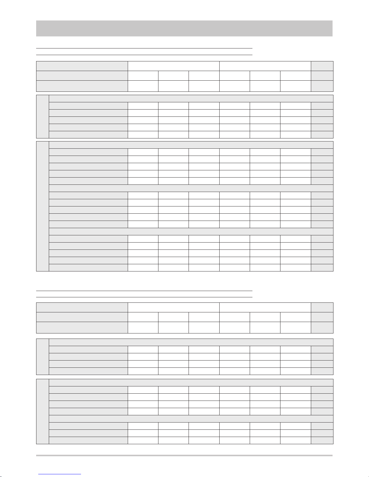
IR
Cooling A35W7 ( source : air in 35°C d.b. / plant : water in 12°C out 7°C )
Cooling capacity 19,9 22,1 25,8 30,8 35,6 40,2
kW
Power input 6,82 7,50 8,76 10,8 12,3 13,9
kW
EER 2,92 2,95 2,95 2,85 2,89 2,89
-
Water flow rate plant side 3432 3809 4444 5319 6143 6932
l/h
Pressure drops plant side 26 31 26 36 31 38
kPa
IP
Cooling A35W7 ( source : air in 35°C d.b. / plant : water in 12°C out 7°C )
Cooling capacity 19,5 21,7 25,3 30,2 34,9 39,4
kW
Power input 6,75 7,42 8,66 10,7 12,2 13,8
kW
EER 2,89 2,92 2,92 2,82 2,86 2,86
-
Water flow rate plant side 3363 3741 4358 5216 6023 6795
l/h
Pressure drops plant side 25 30 25 35 29 37
kPa
Heating A7W45 ( source : air in 7°C d.b. 6°C w.b. / plant : water in 40°C out 45°C )
Heating capacity 21,0 23,3 27,1 32,5 37,6 42,4
kW
Power input 6,49 7,14 8,33 10,3 11,7 13,4
kW
COP 3,24 3,26 3,25 3,16 3,21 3,16
-
Water flow rate plant side 3568 3961 4610 5515 6386 7188
l/h
Pressure drops plant side 27 33 27 38 33 41
kPa
Heating A2W45 ( source : air in 2°C d.b. 1°C w.b. / plant : water in 40°C out 45°C )
Heating capacity 17,4 19,3 22,5 26,8 31,0 35,0
kW
Power input 6,40 7,03 8,21 10,1 11,5 13,2
kW
COP 2,72 2,75 2,74 2,65 2,70 2,65
-
Water flow rate plant side 2954 3278 3825 4559 5276 5942
l/h
Pressure drops plant side 19 23 19 27 23 28
kPa
IR
Cooling A35W7 ( source : air in 35°C d.b. / plant : water in 12°C out 7°C )
Cooling capacity 20,0 22,2 25,9 31,0 35,8 40,4
kW
EER 2,97 3,00 2,99 2,92 2,96 2,95
-
Pressure drops plant side 26 31 25 36 30 38
kPa
ESEER 3,36 3,39 3,38 3,30 3,34 3,33
-
IP
Cooling A35W7 ( source : air in 35°C d.b. / plant : water in 12°C out 7°C )
Cooling capacity 19,6 21,8 25,4 30,4 35,1 39,6
kW
EER 2,94 2,98 2,97 2,90 2,93 2,91
-
Pressure drops plant side 25 30 25 34 29 37
kPa
ESEER 3,32 3,37 3,36 3,28 3,31 3,29
-
Heating A7W45 (air 7 °C bs - 6 °C bu / water 40 - 45 °C )
Heating capacity 20,9 23,2 27,0 32,3 37,4 42,1
kW
COP 3,27 3,30 3,29 3,20 3,25 3,21
-
Pressure drops plant side 28 34 27 39 33 41
kPa
11
TECHNICAL DATA AND PERFORMANCES
Frame
1 2
Model
191 221 261 301 351 401
U.M.
Power supply
400 - 3N - 50 400 - 3N - 50 400 - 3N - 50 400 - 3N - 50 400 - 3N - 50 400 - 3N - 50 V-ph-Hz
NOMINAL performances - Base setting up (VB) - Standard plants
Frame
1 2
Model
191 221 261 301 351 401
U.M.
Power supply
400 - 3N - 50 400 - 3N - 50 400 - 3N - 50 400 - 3N - 50 400 - 3N - 50 400 - 3N - 50 V-ph-Hz
NOMINAL performances - Base setting up (VB) - Standard plants - EUROVENT certified data
Data declared according to EN 14511. The values are referred to units without options and accessories.
Performances referred to an available static head of the fan equal to 150 Pa.
Performances referred to an available static head of the fan equal to 150 Pa.
Page 12
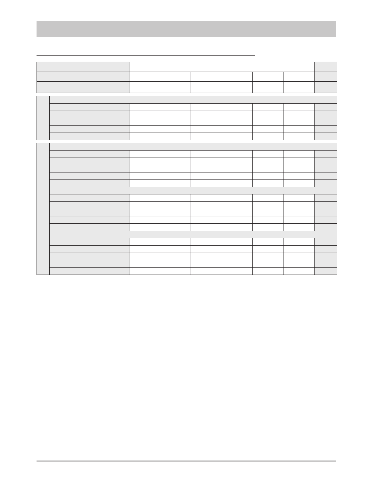
IR
Cooling A35W18 ( source : air in 35°C d.b. / plant : water in 23°C out 18°C )
Cooling capacity 24,6 27,3 31,9 38,1 44,1 49,6
kW
Power input 7,09 7,81 9,11 11,2 12,8 14,6
kW
EER 3,47 3,50 3,50 3,40 3,45 3,40
-
Water flow rate plant side 4259 4723 5513 6595 7625 8604
l/h
Pressure drops plant side 39 47 38 54 46 58
kPa
IP
Cooling A35W18 ( source : air in 35°C d.b. / plant : water in 23°C out 18°C )
Cooling capacity 24,2 26,8 31,3 37,4 43,2 48,7
kW
Power input 7,01 7,73 9,01 11,1 12,7 14,4
kW
EER 3,45 3,47 3,47 3,37 3,40 3,38
-
Water flow rate plant side 4173 4637 5410 6475 7471 8432
l/h
Pressure drops plant side 37 45 37 52 44 56
kPa
Heating A7W35 ( source : air in 7°C d.b. 6°C w.b. / plant : water in 30°C out 35°C )
Heating capacity 21,4 23,8 27,7 33,2 38,4 43,3
kW
Power input 5,48 6,03 7,03 8,71 9,91 11,3
kW
COP 3,91 3,95 3,94 3,81 3,87 3,83
-
Water flow rate plant side 3651 4063 4731 5657 6549 7371
l/h
Pressure drops plant side 29 35 29 40 34 43
kPa
Heating A2W35 ( source : air in 2°C d.b. 1°C w.b. / plant : water in 30°C out 35°C )
Heating capacity 17,8 19,8 23,0 27,5 31,8 35,9
kW
Power input 5,39 5,92 6,90 8,54 9,72 11,1
kW
COP 3,30 3,34 3,33 3,22 3,27 3,23
-
Water flow rate plant side 3034 3377 3926 4697 5434 6120
l/h
Pressure drops plant side 20 25 20 28 24 30
kPa
12
TECHNICAL DATA AND PERFORMANCES
Frame
1 2
Model
191 221 261 301 351 401
U.M.
Power supply
400 - 3N - 50 400 - 3N - 50 400 - 3N - 50 400 - 3N - 50 400 - 3N - 50 400 - 3N - 50 V-ph-Hz
NOMINAL performances - Base setting up (VB) - Radiant plants
Data declared according to EN 14511. The values are referred to units without options and accessories.
Performances referred to an available static head of the fan equal to 150 Pa.
Page 13
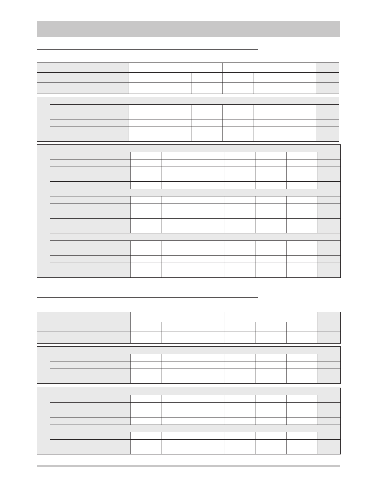
IR
Cooling A35W7 ( source : air in 35°C d.b. / plant : water in 12°C out 7°C )
Cooling capacity 19,1 21,2 24,8 29,6 34,2 38,6
kW
Power input 7,34 8,09 9,42 11,6 13,3 15,0
kW
EER 2,60 2,62 2,63 2,55 2,57 2,57
-
Water flow rate plant side 3295 3655 4273 5113 5903 6658
l/h
Pressure drops plant side 24 29 24 33 28 36
kPa
IP
Cooling A35W7 ( source : air in 35°C d.b. / plant : water in 12°C out 7°C )
Cooling capacity 18,7 20,8 24,3 29,1 33,6 37,8
kW
Power input 7,27 8,00 9,33 11,4 13,1 14,9
kW
EER 2,57 2,60 2,60 2,55 2,56 2,54
-
Water flow rate plant side 3226 3586 4187 5010 5783 6520
l/h
Pressure drops plant side 23 28 23 32 27 34
kPa
Heating A7W45 ( source : air in 7°C d.b. 6°C w.b. / plant : water in 40°C out 45°C )
Heating capacity 19,9 22,2 25,8 31,0 35,8 40,3
kW
Power input 6,22 6,85 7,98 9,88 11,3 12,8
kW
COP 3,20 3,24 3,23 3,14 3,17 3,15
-
Water flow rate plant side 3381 3773 4388 5259 6078 6847
l/h
Pressure drops plant side 25 30 25 35 30 37
kPa
Heating A2W45 ( source : air in 2°C d.b. 1°C w.b. / plant : water in 40°C out 45°C )
Heating capacity 16,4 18,3 21,3 25,5 29,5 33,2
kW
Power input 6,13 6,74 7,87 9,73 11,1 12,6
kW
COP 2,68 2,72 2,71 2,62 2,66 2,63
-
Water flow rate plant side 2800 3107 3620 4337 5020 5651
l/h
Pressure drops plant side 17 21 17 24 21 26
kPa
Frame
1 2
Model
191 221 261 301 351 401
U.M.
Power supply
400 - 3N - 50 400 - 3N - 50 400 - 3N - 50 400 - 3N - 50 400 - 3N - 50 400 - 3N - 50 V-ph-Hz
IR
Cooling A35W7 ( source : air in 35°C d.b. / plant : water in 12°C out 7°C )
Cooling capacity 19,2 21,3 24,9 29,8 34,4 38,8
kW
EER 2,64 2,67 2,67 2,61 2,63 2,62
-
Pressure drops plant side 24 29 24 33 28 35
kPa
ESEER 2,98 3,02 3,02 2,95 2,97 2,96
-
IP
Cooling A35W7 ( source : air in 35°C d.b. / plant : water in 12°C out 7°C )
Cooling capacity 18,8 20,9 24,4 29,2 33,7 38,0
kW
EER 2,61 2,64 2,64 2,58 2,59 2,59
-
Pressure drops plant side 23 28 23 32 27 34
kPa
ESEER 2,95 2,98 2,98 2,92 2,93 2,93
-
Heating A7W45 (air 7 °C bs - 6 °C bu / water 40 - 45 °C )
Heating capacity 19,8 22,1 25,7 30,8 35,6 40,1
kW
COP 3,22 3,28 3,26 3,17 3,21 3,18
-
Pressure drops plant side 25 31 25 35 30 38
kPa
13
TECHNICAL DATA AND PERFORMANCES
Frame
1 2
Model
191 221 261 301 351 401
U.M.
Power supply
400 - 3N - 50 400 - 3N - 50 400 - 3N - 50 400 - 3N - 50 400 - 3N - 50 400 - 3N - 50 V-ph-Hz
NOMINAL performances - Low noise setting up (AS) - Standard plants
NOMINAL performances - Low noise setting up (AS) - Standard plants - EUROVENT certified data
Data declared according to EN 14511. The values are referred to units without options and accessories.
Performances referred to an available static head of the fan equal to 150 Pa.
Performances referred to an available static head of the fan equal to 150 Pa.
Page 14
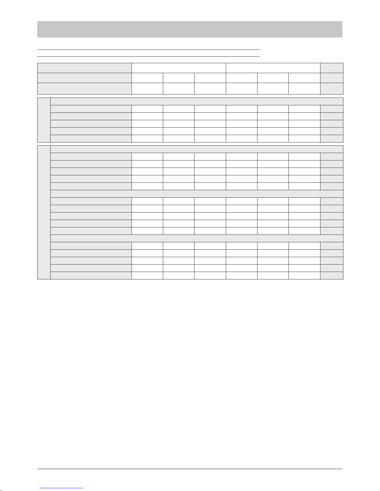
IR
Cooling A35W18 ( source : air in 35°C d.b. / plant : water in 23°C out 18°C )
Cooling capacity 23,7 26,2 30,7 36,7 42,4 47,7
kW
Power input 7,62 8,41 9,79 12,0 13,8 15,6
kW
EER 3,11 3,12 3,14 3,06 3,07 3,06
-
Water flow rate plant side 4087 4534 5307 6354 7333 8261
l/h
Pressure drops plant side 36 43 36 50 43 54
kPa
IP
Cooling A35W18 ( source : air in 35°C d.b. / plant : water in 23°C out 18°C )
Cooling capacity 23,2 25,7 30,1 35,9 41,5 46,7
kW
Power input 7,55 8,32 9,69 11,9 13,7 15,5
kW
EER 3,07 3,09 3,11 3,02 3,03 3,01
-
Water flow rate plant side 4002 4448 5204 6217 7179 8089
l/h
Pressure drops plant side 34 42 34 48 41 51
kPa
Heating A7W35 ( source : air in 7°C d.b. 6°C w.b. / plant : water in 30°C out 35°C )
Heating capacity 20,3 22,6 26,3 31,6 36,5 41,2
kW
Power input 5,24 5,77 6,73 8,34 9,49 10,9
kW
COP 3,87 3,92 3,91 3,79 3,85 3,78
-
Water flow rate plant side 3463 3857 4491 5383 6223 7011
l/h
Pressure drops plant side 26 32 26 37 31 39
kPa
Heating A2W35 ( source : air in 2°C d.b. 1°C w.b. / plant : water in 30°C out 35°C )
Heating capacity 16,8 18,8 21,8 26,2 30,2 34,0
kW
Power input 5,16 5,67 6,61 8,19 9,32 10,6
kW
COP 3,26 3,32 3,30 3,20 3,24 3,21
-
Water flow rate plant side 2880 3206 3720 4474 5160 5811
l/h
Pressure drops plant side 18 22 18 26 22 27
kPa
14
TECHNICAL DATA AND PERFORMANCES
Frame
1 2
Model
191 221 261 301 351 401
U.M.
Power supply
400 - 3N - 50 400 - 3N - 50 400 - 3N - 50 400 - 3N - 50 400 - 3N - 50 400 - 3N - 50 V-ph-Hz
NOMINAL performances - Low noise setting up (AS) - Radiant plants
Data declared according to EN 14511. The values are referred to units without options and accessories.
Performances referred to an available static head of the fan equal to 150 Pa.
Page 15
15
0.4
0.6
0.8
1.0
1.2
1.4
1.6
1.8
2.0
15 20 25 30 35 40 45 50
0.5
0.6
0.7
0.8
0.9
1.0
1.1
1.2
1.3
1.4
1.5
15 20 25 30 35 40 45 50
0.5
0.6
0.7
0.8
0.9
1.0
1.1
1.2
1.3
1.4
1.5
15 20 25 30 35 40 45 50
TECHNICAL DATA AND PERFORMANCES
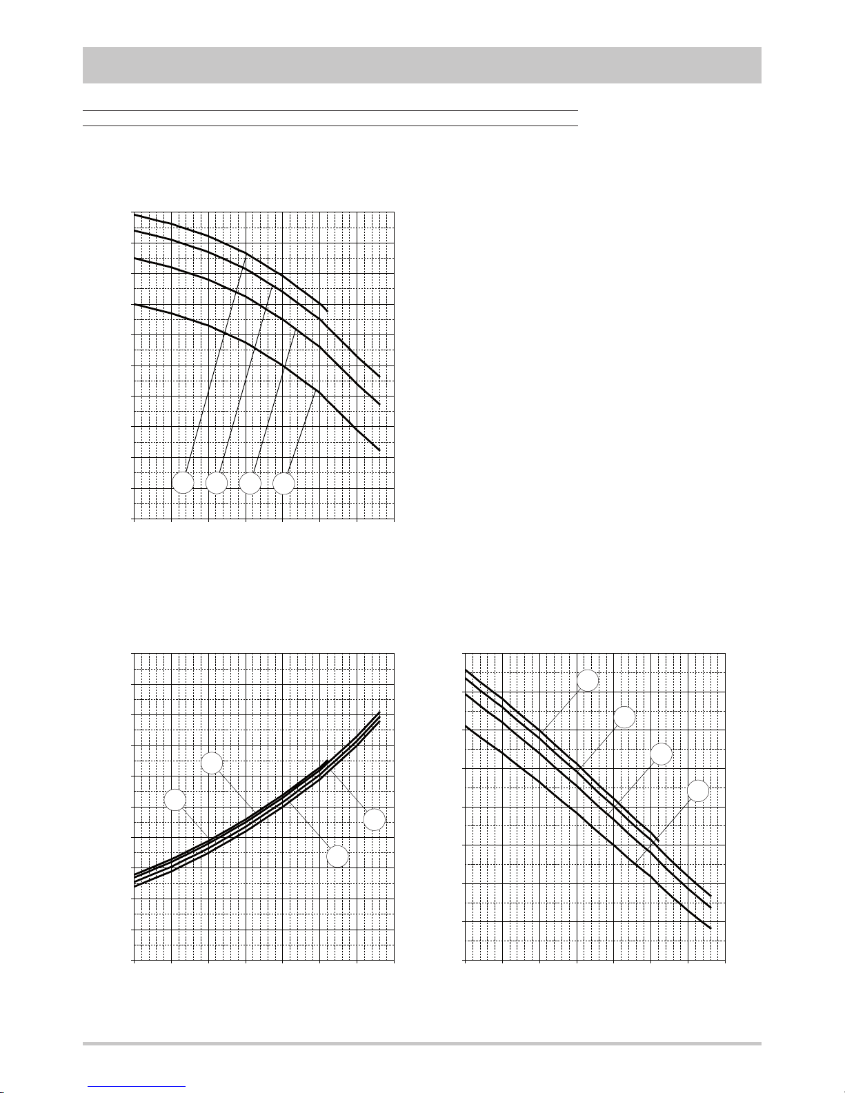
COOLING performances
The graphs allow to get the corrective factors to
be applied to the nominal performances in order
to obtain the real performances in the selected
operating conditions.
The reference nominal condition is :
A35W7
source : air in 35°C d.b.
plant : water in 12°C out 7°C
Outlet temperature
plant side :
A = 24°C
B = 18°C
C = 12°C
D = 7°C
Cooling capacity
Inlet air temperature d.b. [°C]
Inlet air temperature d.b. [°C] Inlet air temperature d.b. [°C]
Power input EER
A
B
C
D
A
B
C
D
A
B
C
D
Page 16
16
0.4
0.6
0.8
1.0
1.2
1.4
1.6
1.8
2.0
-15 -10 -5 0 5 10 15 20
0.5
0.6
0.7
0.8
0.9
1.0
1.1
1.2
1.3
1.4
1.5
-15 -10 -5 0 5 10 15 20
0,5
0,6
0,7
0,8
0,9
1,0
1,1
1,2
1,3
1,4
1,5
-15 -10 -5 0 5 10 15 20
TECHNICAL DATA AND PERFORMANCES
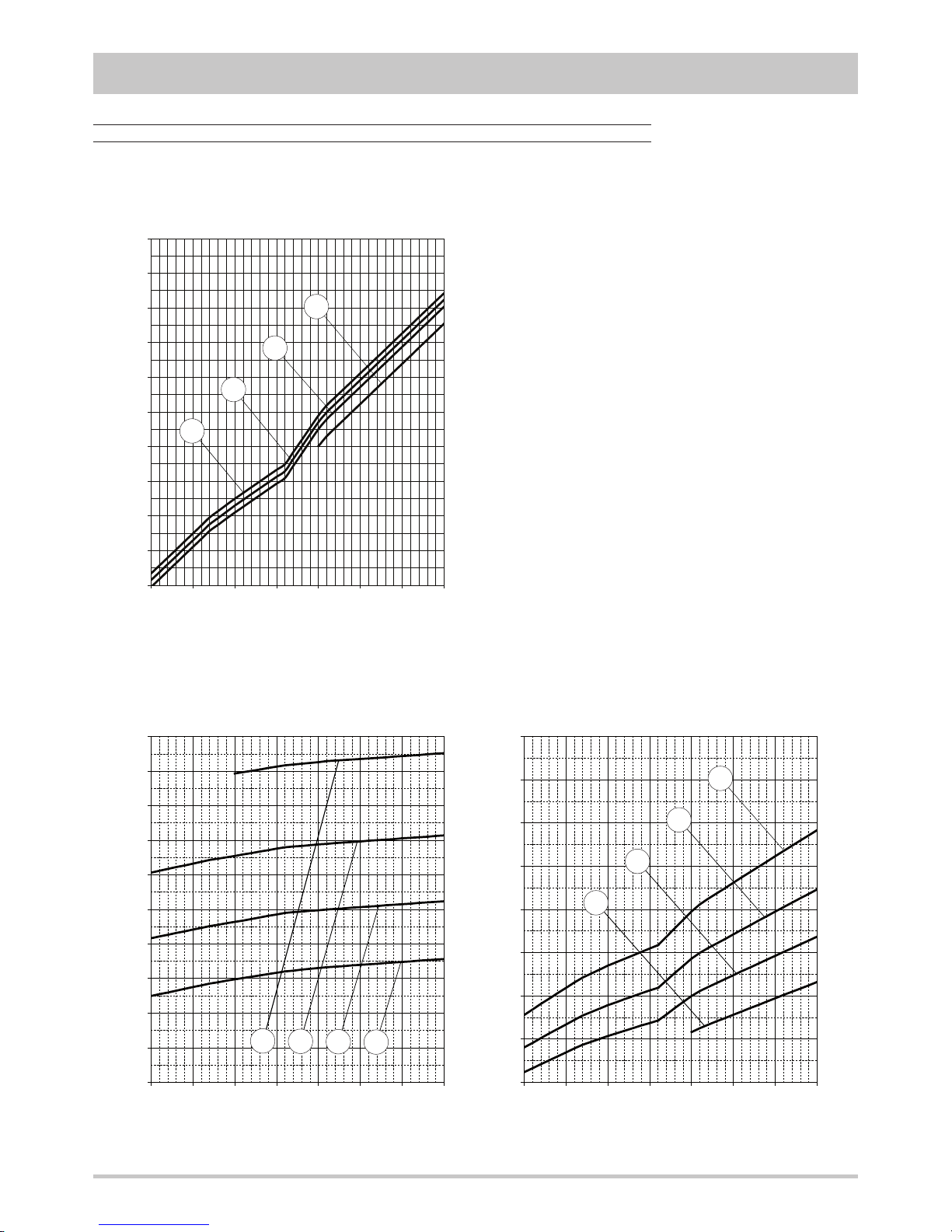
HEATING performances
The graphs allow to get the corrective factors to
be applied to the nominal performances in order
to obtain the real performances in the selected
operating conditions.
The reference nominal condition is :
A7W35
source : air in 7°C d.b. 6°C w.b.
plant : water in 30°C out 35°C
Outlet temperature
plant side :
A = 55°C
B = 45°C
C = 35°C
D = 25°C
Heating capacity
Inlet air temperature w.b. [°C]
Inlet air temperature w.b. [°C] Inlet air temperature w.b. [°C]
Power input COP
D
C
B
A
A
B
C
D
A
B
C
D
Page 17
17
0
10
20
30
40
50
60
0 1000 2000 3000 4000 5000 6000 7000 8000 9000
TECHNICAL DATA AND PERFORMANCES
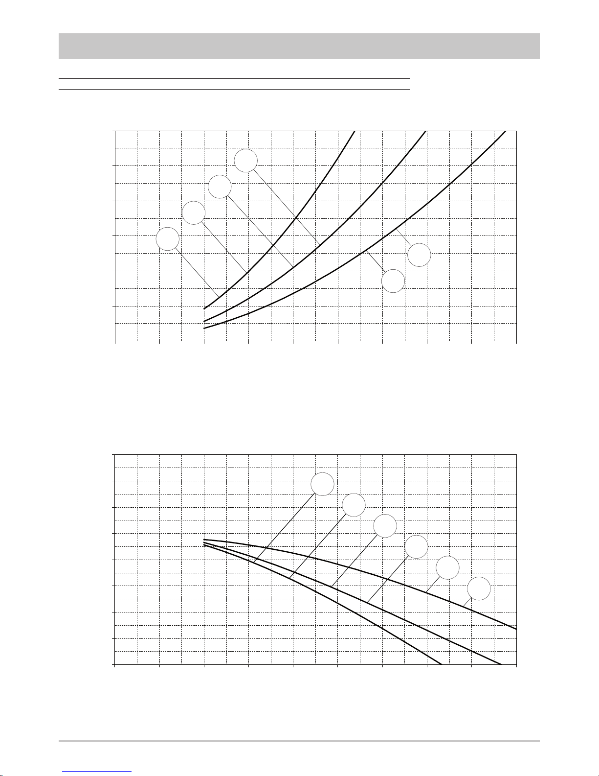
Plant side hydraulic performances
Pressure drops - unit without options
The graphs are referred to units operating with water at the temperature of 10°C (density 1000 kg/m3).
Flow rate [ l/h ]
Pressure drops [ kPa ]
0
40
80
120
160
200
240
280
320
0 1000 2000 3000 4000 5000 6000 7000 8000 9000
Available static head - unit with option “Storing and pumping module” :
“Standard pump” or "Tank and standard pump"
Flow rate [ l/h ]
Available static head [ kPa ]
19.1
22.1
26.1
30.1
35.1
40.1
19.1
22.1
26.1
30.1
35.1
40.1
Page 18
18
TECHNICAL DATA AND PERFORMANCES
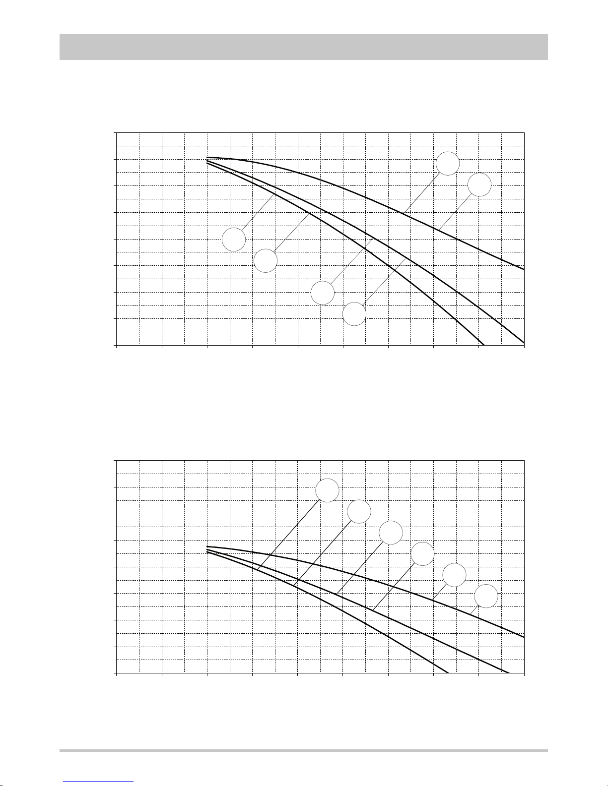
Available static head - unit with option “Storing and pumping module” :
“High head pump” or "Tank and high head pump"
Flow rate [ l/h ]
Available static head [ kPa ]
0
40
80
120
160
200
240
280
320
0 1000 2000 3000 4000 5000 6000 7000 8000 9000
Available static head - unit with option “Storing and pumping module” :
“Modulating pump” or "Tank and modulating pump"
The graphs are referred to units operating with water at the temperature of 10°C (density 1000 kg/m3).
Flow rate [ l/h ]
Available static head [ kPa ]
19.1
22.1
26.1
30.1
35.1
40.1
0
40
80
120
160
200
240
280
320
0 1000 2000 3000 4000 5000 6000 7000 8000 9000
26.1
30.1
35.1
40.1
19.1
22.1
Page 19
19
TECHNICAL DATA AND PERFORMANCES
0
20
40
60
80
100
120
140
160
180
200
4000 6000 8000 10000 12000 14000 16000 18000 20000 22000
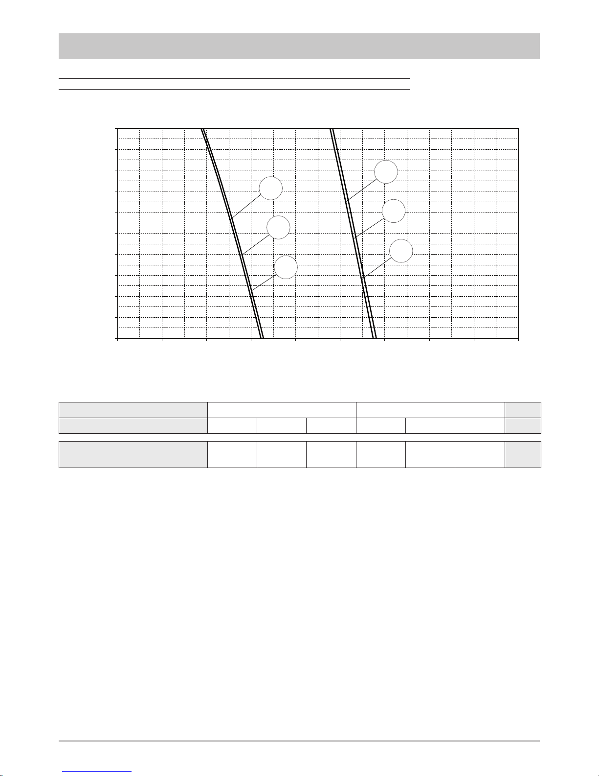
In case of ducted installation the total pressure drops in the inlet and outlet ducts can not exceed the maximum available static head.
The minimum duct section must guarantee that the medium air velocity does not exceed 2,5 m/s in order to avoid noise problems and
to keep the pressure drops lower as possible.
Source side aeraulic performances
Available static head
Flow rate [ m3/h ]
Available static head [ Pa ]
Frame
1 2
Model
191 221 261 301 351 401
U.M.
Maximum available static head
200 200 200 200 200 200 Pa
The graphs are referred to units operating with air at the temperature of 15°C (density 1,2 kg/m3).
35.1
30.1
40.1
22.1
19.1
26.1
Page 20
20
TECHNICAL DATA AND PERFORMANCES
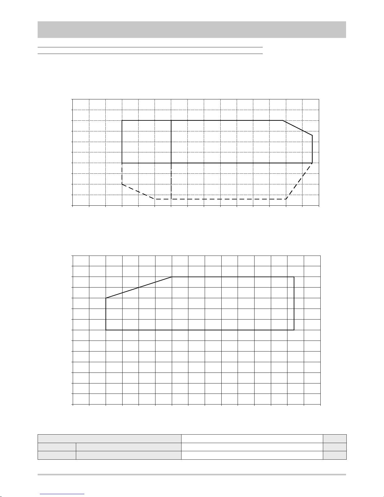
Operating limits
-15
-10
-5
0
5
10
15
20
25
30
35
-25 -20 -15 -10 -5 0 5 10 15 20 25 30 35 40 45 50
COOLING
Inlet air temperature d.b. [°C]
Outlet temperature - plant side [°C]
-5
0
5
10
15
20
25
30
35
40
45
50
55
60
65
-25 -20 -15 -10 -5 0 5 10 15 20 25 30 35 40 45 50
HEATING
Inlet air temperature d.b. [°C]
Outlet temperature - plant side [°C]
The graphs reported below show the operating area inside which the correct working of the unit is guaranteed.
Temperature difference between unit inlet and outlet Plant side
DT max Maximum value 8
°C
DT min Minimum value 3
°C
BRINE units (BR and BP)
Modulating fans
control
(condensation
control)
Page 21
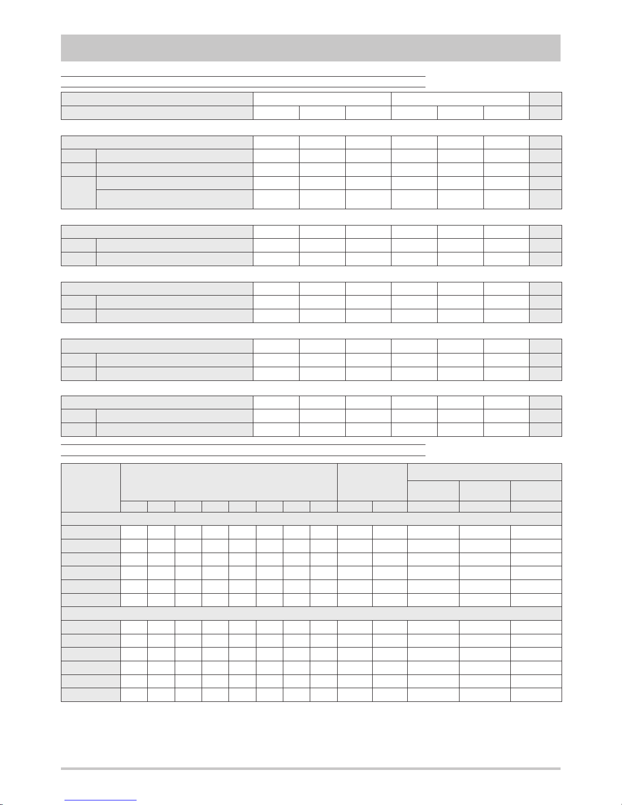
21
Electrical data
Frame
1 2
Model
191 221 261 301 351 401
U.M.
Power supply 400-3N-50 400-3N-50 400-3N-50 400-3N-50 400-3N-50 400-3N-50
V-ph-Hz
F.L.A. Maximum total current input 28,9 30,9 33,0 28,0 32,0 36,1
A
F.L.I. Maximum total power input 13,0 14,3 15,6 16,8 19,4 22,0
kW
M.I.C.
Maximum total start current 108 124 131 131 146 180
A
Maximum total start current
with soft starter (option)
65 74 78 75 84 104
A
Unit
Power supply 230-1-50 230-1-50 230-1-50 230-1-50 230-1-50 230-1-50
V-ph-Hz
F.L.A. Maximum total current input 3,6 3,6 3,6 3,6 5,1 5,1
A
F.L.I. Maximum total power input 0,7 0,7 0,7 0,7 1,0 1,0
kW
Standard pump (option)
Power supply 230-1-50 230-1-50 230-1-50 230-1-50 230-1-50 230-1-50
V-ph-Hz
F.L.A. Maximum total current input 6,1 6,1 6,1 6,1 8,2 8,2
A
F.L.I. Maximum total power input 1,2 1,2 1,2 1,2 1,6 1,6
kW
High head pump (option)
Power supply 400-3N-50 400-3N-50 400-3N-50 400-3N-50 400-3N-50 400-3N-50
V-ph-Hz
F.L.A. Maximum total current input 3,6 3,6 3,6 3,6 5,1 5,1
A
F.L.I. Maximum total power input 0,7 0,7 0,7 0,7 1,0 1,0
kW
Modulating pump (option)
Power supply 400-3N-50 400-3N-50 400-3N-50 400-3N-50 400-3N-50 400-3N-50
V-ph-Hz
F.L.A. Maximum total current input 9,5 9,5 9,5 9,5 9,5 9,5
A
F.L.I. Maximum total power input 6,6 6,6 6,6 6,6 6,6 6,6
kW
Integrative electrical heaters standard in the tank (option)
TECHNICAL DATA AND PERFORMANCES
Noise levels
Model
Sound power levels [dB]
by octave bands [Hz]
Sound power
level
Sound pressure level
at 1 metre at 5 metres at 10 metres
63 125 250 500 1000 2000 4000 8000 [dB] [dB(A)] [dB(A)] [dB(A)] [dB(A)]
Base setting up (AB)
191
85,1 79,4 74,3 73,2 71,3 68,4 62,6 57,6 87 76 60 50 45
221
85,3 79,6 74,5 73,4 71,5 68,6 62,8 57,8 87 76 60 50 45
261
86,3 80,6 75,5 74,4 72,5 69,6 63,8 58,8 88 77 61 51 46
301
89,3 83,6 78,5 77,4 75,5 72,6 66,8 61,8 91 80 64 54 49
351
89,8 84,1 79,0 77,9 76,0 73,1 67,3 62,3 92 81 65 55 49
401
90,3 84,6 79,5 78,4 76,5 73,6 67,8 62,8 92 81 65 55 50
Low noise setting up (AS)
191
83,1 77,4 72,3 71,2 69,3 66,4 60,6 55,6 85 74 58 48 43
221
83,3 77,6 72,5 71,4 69,5 66,6 60,8 55,8 85 74 58 48 43
261
84,3 78,6 73,5 72,4 70,5 67,6 61,8 56,8 86 75 59 49 44
301
87,3 81,6 76,5 75,4 73,5 70,6 64,8 59,8 89 78 62 52 47
351
87,8 82,1 77,0 75,9 74,0 71,1 65,3 60,3 90 79 63 53 47
401
88,3 82,6 77,5 76,4 74,5 71,6 65,8 60,8 90 79 63 53 48
Reference conditions
Performances referred to units operating in cooling mode at nominal conditions A35W7.
Unit placed in free field on reflecting surface (directional factor equal to 2).
Unit ducted on the sunction and on the flow side for 2 meters.
The sound power level is measured according to ISO 3744 standard.
The sound pressure level is calculated according to ISO 3744 and is referred to a distance of 1/5/10 metres from the external surface of the unit.
Page 22
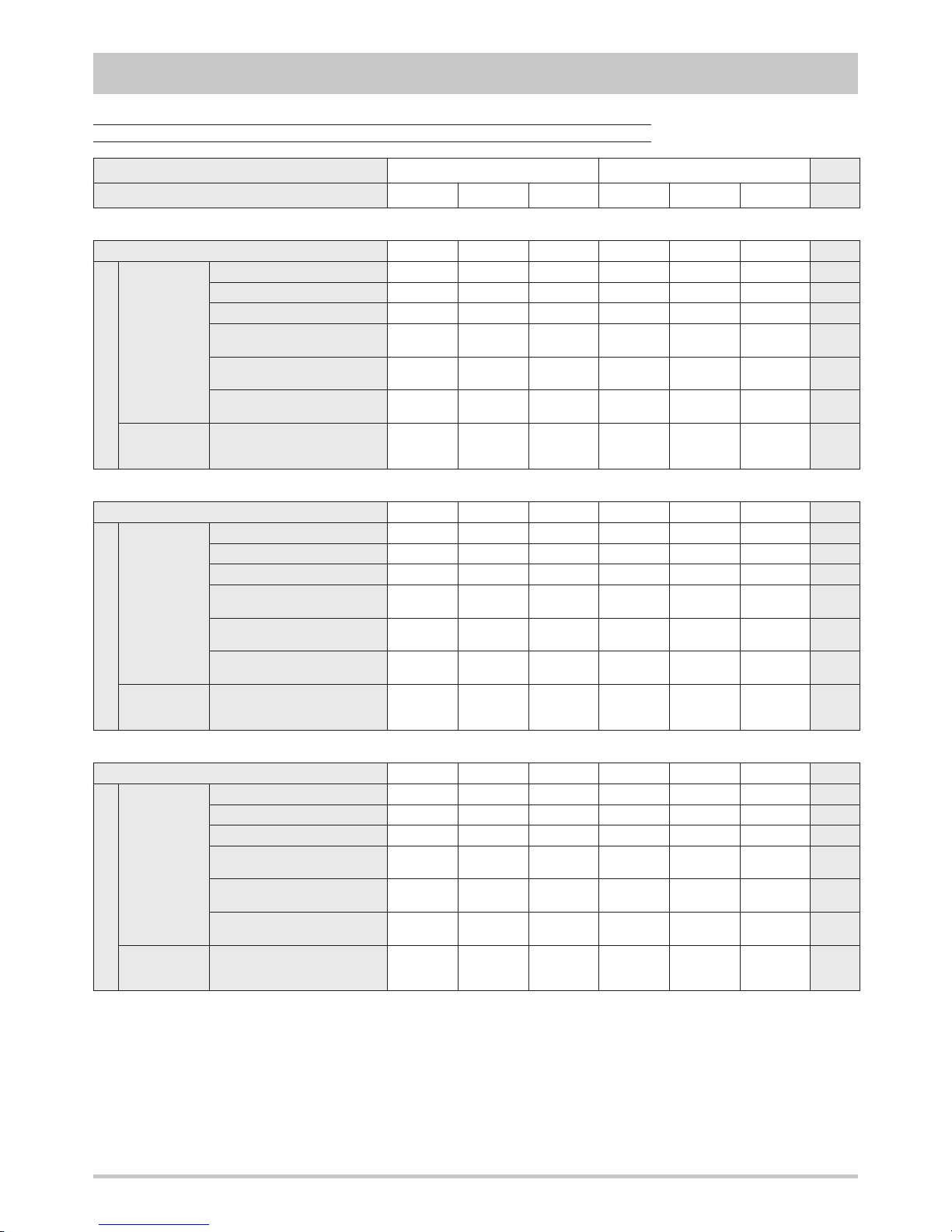
Unit without options 255 258 276 276 299 301
kg
Options
Storing
and
pumping
module
Standard pump 9 9 9 9 11 11
kg
High head pump 12 12 12 12 13 13
kg
Modulating pump 12 12 12 14 16 16
kg
Tank and
standard pump
31 31 31 31 33 33
kg
Tank and
high head pump
34 34 34 34 35 35
kg
Tank and
modulating pump
34 34 34 36 38 38
kg
Integrative
electrical
heaters
Standard in the tank 5 5 5 5 5 5
kg
Components weights
Unità senza opzioni 271 274 292 296 319 321
kg
Options
Storing
and
pumping
module
Standard pump 9 9 9 9 11 11
kg
High head pump 12 12 12 12 13 13
kg
Modulating pump 12 12 12 14 16 16
kg
Tank and
standard pump
31 31 31 31 33 33
kg
Tank and
high head pump
34 34 34 34 35 35
kg
Tank and
modulating pump
34 34 34 36 38 38
kg
Integrative
electrical
heaters
Standard in the tank 5 5 5 5 5 5
kg
Transport weights
Unità senza opzioni 259 262 281 281 305 307
kg
Options
Storing
and
pumping
module
Standard pump 10 10 10 10 12 12
kg
High head pump 13 13 13 13 14 14
kg
Modulating pump 13 13 13 15 17 17
kg
Tank and
standard pump
117 117 117 117 119 119
kg
Tank and
high head pump
120 120 120 120 121 121
kg
Tank and
modulating pump
120 120 120 122 124 124
kg
Integrative
electrical
heaters
Standard in the tank 5 5 5 5 5 5
kg
Operating weights
22
TECHNICAL DATA AND PERFORMANCES
Frame
1 2
Model
191 221 261 301 351 401
U.M.
Weights
Page 23
23
TECHNICAL DATA AND PERFORMANCES
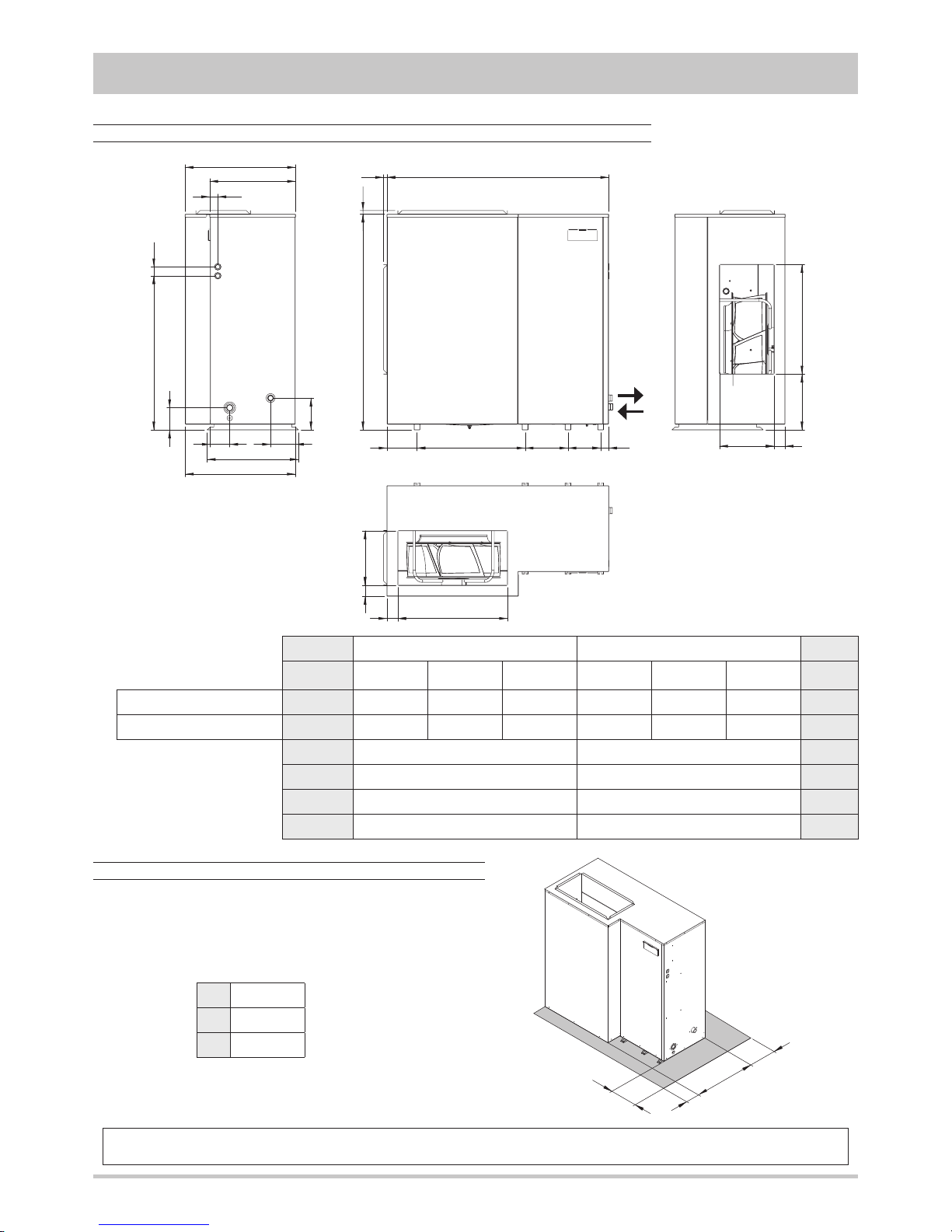
Overall dimensions
Minimum operating area
Respect the free area around the unit as shown in the
figure in order to guarantee a good accessibility and
facilitate maintenance and control operations.
A 400 mm
B 450 mm
C 200 mm
744
150
1038 60
167
741
202 E 288 220 53
D
1453 24
53
576
131
614
215
G F
73368
74 F
73 368
24
1
2
1
2
B
C
A
Plant return
Plant flow
Frame
1 2
Model
191 221 261 301 351 401
1 1"1/4 F 1"1/4 F 1"1/4 F 1"1/4 F 1"1/4 F 1"1/4 F
-
2
1"1/4 M 1"1/4 M 1"1/4 M 1"1/4 M 1"1/4 M 1"1/4 M
-
D 1494 1704
mm
E 728 938
mm
F
738 948
mm
G
376 271
mm
The manufacturer declines all responsibility for any inaccuracies in this manual due to printing or typing errors.
The reserves the right to modify the products contents in this catalogue without previous notice.
Page 24

Cod. 3QE29590
 Loading...