

Ferroli Optimax HE 31 C, OPTIMAX HE 38 C, Optimax HE Plus 38 C Instructions For Installation, Use And Maintenance Manual
Page 1
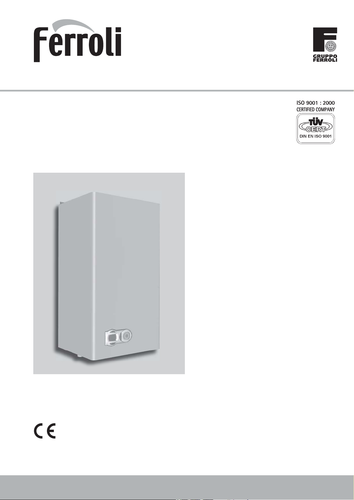
OPTIMAX HE 31 C
wall-mounted gas fired,
pre-mix
condensing combination boiler
cod. 3540E64/1 - 11/2006
INSTRUCTIONS FOR USE INSTALLATION AND MAINTENANCE
FOR THE UNITED KINGDOM AND EIRE
G.C. n° 47-267-42
Page 2
OPTIMAX HE 31 C
IMPORTANT
• Your "benchmark" Installation, Commissioning and Service Record Log Book is enclosed in the
last pages of this manual. “This record must be completed and left with the end user”.
Ferroli is a member of the Benchmark initiative and fully supports the aims of the programme.
Benchmark has been introduced to improve the standards of installation and commissioning of
central heating systems in the UK and to encourage the regular servicing of all central heating
systems to ensure safety and efficiency. Please see installation and servicing guidelines.
For EIRE ( Southern Ireland ) it is necessary to complete a “Declaration of Conformity “ to indicate
compliance to I.S. 813. An example of this is given in the current edition of I.S. 813. In addition
it is necessary to complete the “Benchmark” logbook.
• "Ferroli declare that no substances harmful to health are contained in the appliance or used
during the appliance manufacture”.
This symbol indicates “Caution” and is placed next to all safety information.
Strictly follow these instructions in order to avoid danger and damage to persons,
or property.
This symbol calls attention to a note or important information, please read thoroughly.
• Read the warnings given in this manual thoroughly.
They provide important information for safe installation, use and maintenance
• By law the instruction manual must be left with the
end user.
• If the appliance is sold or transferred to another
owner or if the owner moves, leaving the appliance
behind, always ensure that the manual is kept with
the appliance for consultation by the new owner
and /or installer.
• Incorrect installation or poor maintenance absolves
the manufacturer from all liability for damage to
people or property.
• Installation and maintenance must be carried out
in conformity with current legislation, according
to the manufacturer’s instructions and by qualified
personnel.
• Before service or maintenance work is, carried out
isolate the appliance from the mains electricity
supply.
• In the event of malfunction or faulty operation, isolate the appliance. Do not attempt to repair or carry
out any other operation on the appliance directly.
Contact qualified personnel only.
• Repairs or the replacement of components must be
carried out exclusively by qualified personnel using
original spare parts only. Failure to respect the above
may compromise the safety of the appliance.
• To guarantee efficient operation, the appliance must
be serviced once a year by a corgi registered engineer.
• The appliance may not be used for purposes other
than those for which it was explicitly designed. Any
other use is considered improper and therefore dangerous.
• Incorrect installation and use or failure to follow the
instructions provided by the manufacturer absolve
the manufacturer from all liability for damage.
• After unpacking, check that the contents are complete
and undamaged.
• Keep the packaging out of reach of children as it is
potentially hazardous.
• To clean external parts, use a damp cloth moistened
with soapy water if necessary. Avoid using abrasive
cleaning products and solvents.
2
Page 3
OPTIMAX HE 31 C
1. OPERATING INSTRUCTIONS .................................................................4
1.1 Introduction ............................................................................................................4
1.2 Control panel ..........................................................................................................5
1.3 Turning ON and OFF ..............................................................................................6
1.4 Adjustments ............................................................................................................8
1.5 Maintenance ..........................................................................................................11
1.6 Faults .....................................................................................................................11
2. INSTALLATION .....................................................................................12
2.1 General Instructions ..............................................................................................12
2.2 Boiler location .......................................................................................................13
2.3 Boiler water connections ......................................................................................14
2.4 Connection to the gas system ..............................................................................16
2.5 Electrical Connections ..........................................................................................16
2.6 Flue system ...........................................................................................................18
2.7 Condensate outlet connection .............................................................................24
3. SERVICE AND MAINTENANCE ............................................................26
3.1 Adjustments ..........................................................................................................26
3.2 System start-up .....................................................................................................27
3.3 Maintenance ..........................................................................................................28
3.4 Troubleshooting ....................................................................................................30
4. TECHNICAL CHARACTERISTICS AND DATA ..........................................................32
4.1 Dimensions and connections ................................................................................32
4.2 General view and main components ....................................................................33
4.3 Hydraulic diagram .................................................................................................34
4.4 Technical data table ..............................................................................................35
4.5 Diagrams ...............................................................................................................36
4.6 Wiring diagram .....................................................................................................37
cod. 3540E64/1
BENCHMARK ...........................................................................................38
3
Page 4
OPTIMAX HE 31 C
1. OPERATING INSTRUCTIONS
1.1 Introduction
Dear Customer,
Thank you for choosing the OPTIMAX HE 31 C, a FERROLI wall-mounted boiler of the latest generation,
featuring advanced design and cutting-edge technology.
OPTIMAX HE 31 C is a high-efficiency condensing pre-mix appliance for heating and hot water pro-
duction with extremely low emissions, running on natural gas or LPG.
The boiler consists of an aluminium laminar heat exchanger providing effective condensation of the
water vapour contained in the flue gases, permitting extremely high efficiency.
Above the heat exchanger, in the boiler, there is a pre-mix burner, with a large ceramic surface, equip-
ped with electronic ignition and ionization flame control, which achieves extremely low emissions while
ensuring high reliability and long life operation.
The boiler is totally room sealed from the installation room: the air needed for combustion is drawn from
outside. The boiler also includes a modulating speed fan, modulating gas valve, pump, expansion vessel,
safety valve, flow sensor, temperature sensors, a safety thermostat and a low water pressure switch.
Thanks to the twin microprocessor control and adjustment system with advanced self-diagnosis, unit
operation is for the most part automatic. The power for heating is automatically governed by the control
system.
The user only has to set the temperature desired inside the home by means of a room thermostat and
appliance temperature control. The adjustment and control system will provide optimum operation
throughout the year.
The display continuously provides information on the unit’s operating status and it is easily possible
to obtain additional information on the sensor temperatures, set-points, etc. or configure them. Any
operating problems associated with the boiler or system is immediately signalled by the display and, if
possible, corrected automatically.
4
Page 5
OPTIMAX HE 31 C
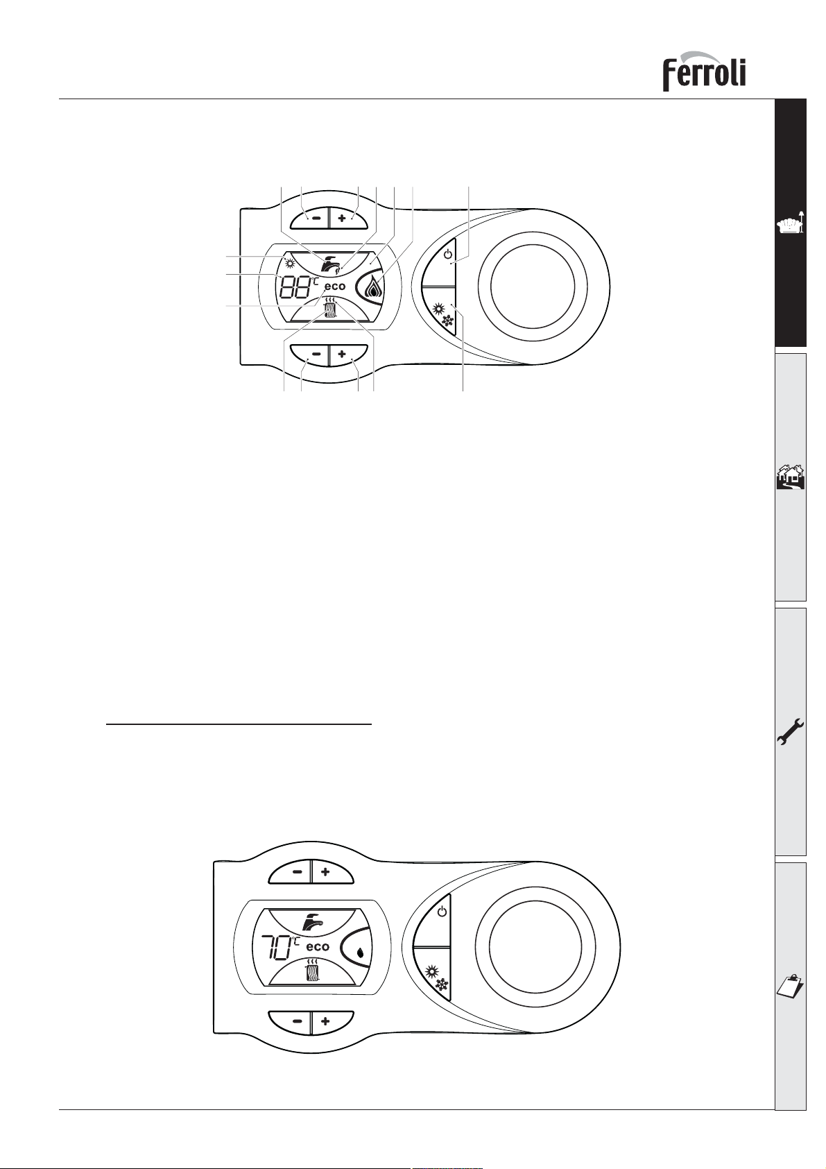
1.2 Control panel
89
10
11
12
21
436
15
comfort
1314
fig. 1
75
eco
reset
1 = Domestic Hot Water temperature setpoint decreasing push button
2 = Domestic Hot Water temperature setpoint increasing push button
3 = Central Heating water temperature setpoint decreasing push button
4 = Central Heating water temperature setpoint increasing push button
5 = Display LCD
6 = Reset / Summer-Winter / OTC push button
7 = Economy-Comfort / On-Off push button
8 = Domestic Hot Water symbol
9 = Domestic Hot Water mode operation
10 = Summer symbol
11 = Multi-function indication
12 = Economy symbol
13 = Central Heating mode operation
14 = Central Heating symbol
15 = Burner on and actual load indication
Indication during boiler operation
Central Heating mode
The Central Heating heat demand (generated by the OpenTherm Remote Control, the Room Thermostat
or the Clock) is indicated by the flashing of the Hot Air symbol over the radiator (part. 13 and 14 – fig.
1). The display indicates the actual Central Heating water temperature (part. 11 – fig. 1).
fig. 2
eco
comfort
reset
5
Page 6
OPTIMAX HE 31 C
Domestic Hot Water mode
The Domestic Hot Water heat demand (generated by the DHW flow sensor or due to a Comfort request)
is indicated by the flashing of the Hot Water symbol under the tap (part. 8 and 9 – fig. 1). The display
indicates the actual Domestic Hot Water temperature (part. 11 – fig. 1).
eco
comfort
reset
fig. 3
1.3 Turning ON and OFF
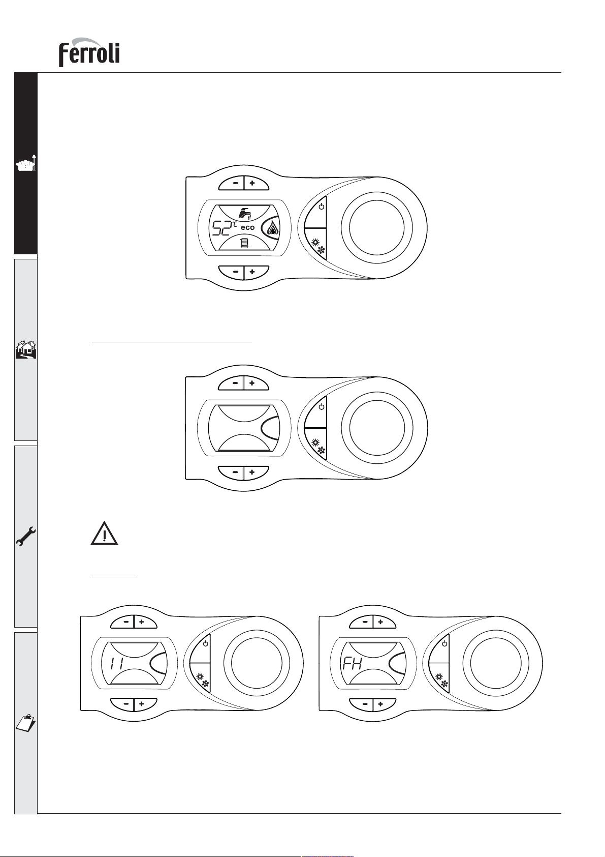
Without main power supply
fig. 4 - Boiler without main power supply
To avoid damage caused by freezing during long shutdowns in winter, it is advisable to drain all
water from the system.
Ignition
Ensure the power is on to the appliance.
eco
comfort
reset
eco
comfort
reset
eco
comfort
reset
fig. 5 Ignition
For the firsts 120 seconds, the display shows FH that identifies the Air purge function.
•
During the first 5 seconds, the display shows the software version of the pcb.
•
Open the gas cock on the boiler and purge the air from the pipework upstream of the gas valve.
•
When the FH disappears, the boiler is ready to function automatically whenever the external controls
•
are calling for heat.
6
Page 7
OPTIMAX HE 31 C
Turning off
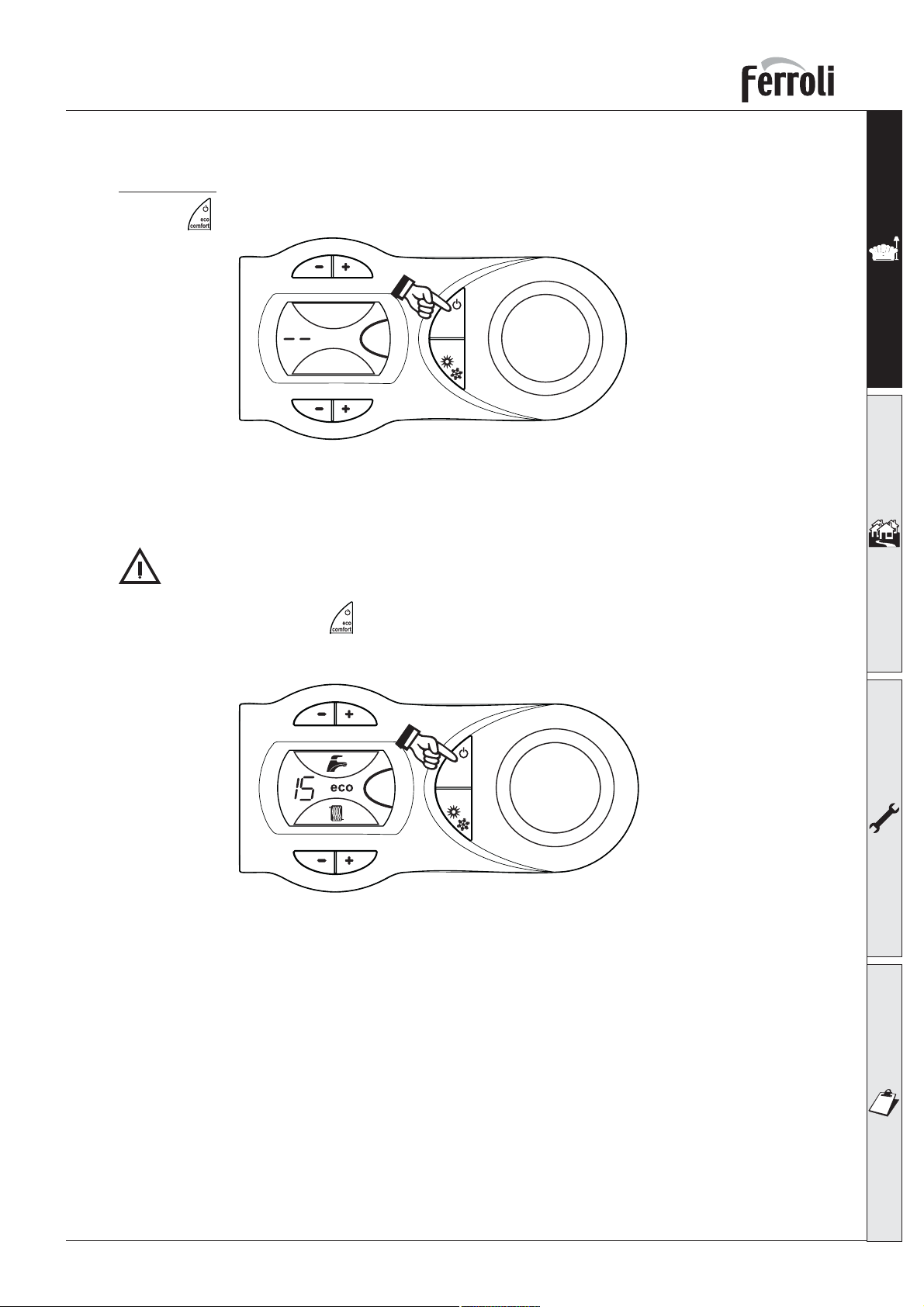
Press the (part. 7 - fig. 1) for 5 seconds.
When the boiler is turned off with this key, the p.c.b is still powered, heating operation is disabled and
the display is off however the frost protection will still be active.
To totally isolate close the gas cock ahead of the boiler and disconnect electrical power.
To avoid damage caused by freezing during long shutdowns in winter, it is advisable to drain all
water from the system.
eco
comfort
reset
fig. 6 - Turning off
To turn boiler on again, press (part.7 - fig.1) for 5 seconds.
eco
comfort
reset
fig. 7
If there is no heat demand, the display shows the actual water pressure (bar/10).
The boiler is ready to function automatically whenever the external controls are calling for heat.
7
Page 8
1.4 Adjustments
Summer/Winter selection
OPTIMAX HE 31 C
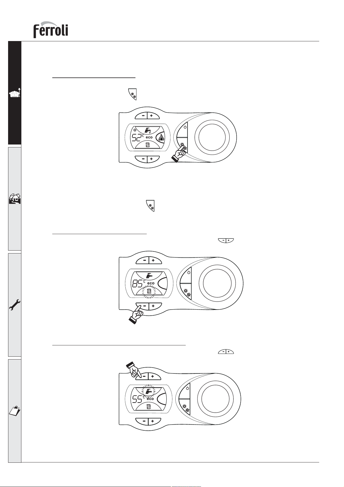
To select Summer, press the
reset
(Part. 6 – fig. 1) for 1 second when the boiler is in Winter mode.
eco
comfort
reset
fig. 8
The display will show the Summer icon (Part 10 – fig. 1): the boiler can still produce domestic hot water
whenever there is a demand. The frost protection remains active.
To select Winter mode, press the
reset
(Part. 6 – fig. 1) for 1 second when the boiler is in Summer
mode.
Heating temperature setting
To set the system flow temperature, use the CH push buttons (Part. 3 and 4 – fig. 1). It can be
varied from a minimum of 20°C to a maximum of 90°C.
eco
comfort
reset
fig. 9
Domestic hot water temperature setting
To set the hot water temperature, use the DHW push buttons (Part. 1 and 2 – fig. 1). It can be
varied from a minimum of 40°C to a maximum of 55°C.
eco
comfort
reset
fig. 10
8
Page 9
OPTIMAX HE 31 C
Room temperature adjustment (using a room thermostat )
Using the room thermostat, set the temperature desired. Controlled by the room thermostat, the boiler
lights and heats the system water to the system delivery setpoint temperature. The burner shuts down
when the desired temperature in the room is reached.
A room thermostat and programmer are a mandatory requirement (Building regulations Doc ‘L’
2002).
Room temperature adjustment (using an optional Remote Control)
Using the remote control, set the temperature desired. The flow temperature will be controlled by the
remote control. For settings and other informations, see the relative manual.
Economy/Comfort selection
The unit is equipped with a special internal device that ensures a high hot-water delivery speed and
excellent user comfort. When comfort mode is active the water in the boiler is maintained at a pre-determined temperature, which means that hot water is available at the boiler outlet as soon as a tap is
opened, ie with no waiting.
The user can turn the device off (ECO mode) by pressing (part.7 - fig.1). In ECO mode the display
shows the relevant symbol (part. 12 - fig. 1). To turn on COMFORT mode, press (part.7 - fig.1) again,
the ECO symbol will vanish from the display.
Outside temperature compensation
When the (optional) external sensor kit is fitted to the appliance, the system can work in Outside temperature compensation mode. In O.T.C. mode the temperature of the heating system is controlled
according to the external climate conditions, this will guarantee a high degree of comfort and energy
saving all year round.
By the CH push buttons (Part. 3 and 4 – fig. 1) is possible to set the maximum flow temperature
for the installation.
O.T.C. setting
reset
To enter the OTC mode, press
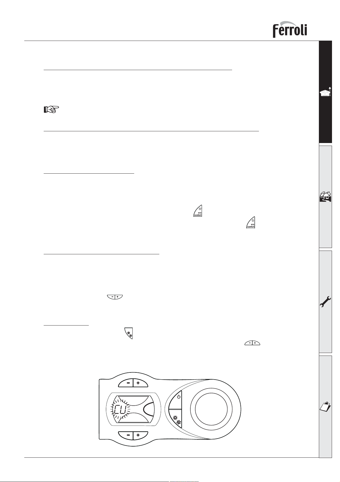
The display shows CU flashing (fig. 11); to set Curve, use the DHW push buttons (Part. 1 and 2 – fig.
1). It can be varied from 1 to 10, in accordance with the chart (fig. 13). O means no O.T.C. mode.
It is recommended a start point of 20 - 30°C and a flow temperature of 85°C is required for the UK
(Curve 9 or 10).
(Part. 6 – fig. 1) for 5 seconds.
eco
comfort
reset
fig. 11
9
Page 10
OPTIMAX HE 31 C
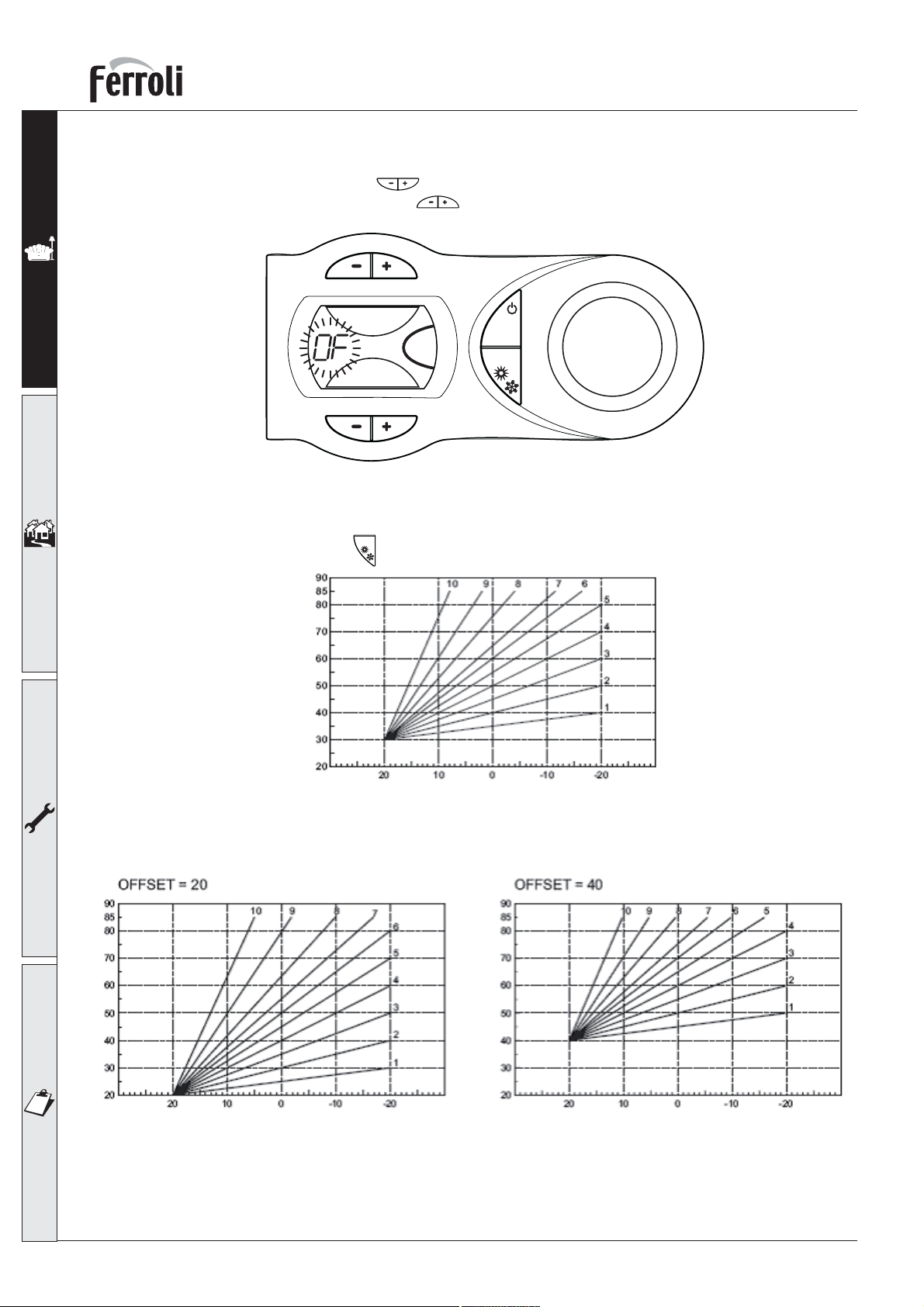
By pressing the CH push buttons (Part. 3 e 4 – fig. 1), the display shows OF flashing (fig. 12); to
set Offset, use the DHW push buttons (Part. 1 and 2 – fig. 1). It can be varied from 20 to 40, in
accordance with the chart (fig. 14).
eco
comfort
reset
fig. 12
To exit the OTC mode, press
Maximum boiler flow temperature
reset
(Part. 6 – fig. 1) for 5 seconds.
Outside temperature
fig. 13
Maximum boiler flow temperature
10
Outside temperature
Maximum boiler flow temperature
Outside temperature
fig. 14
Page 11
OPTIMAX HE 31 C
1.5 Maintenance
It is strongly recommended to carry out annual maintenance of the boiler and heating system. Please
refer to the “maintenance” section in this manual.
The casing, the control panel and the aesthetic parts of the boiler can be cleaned using a soft and damp
cloth, do not use abrasives or solvents.
1.6 Faults
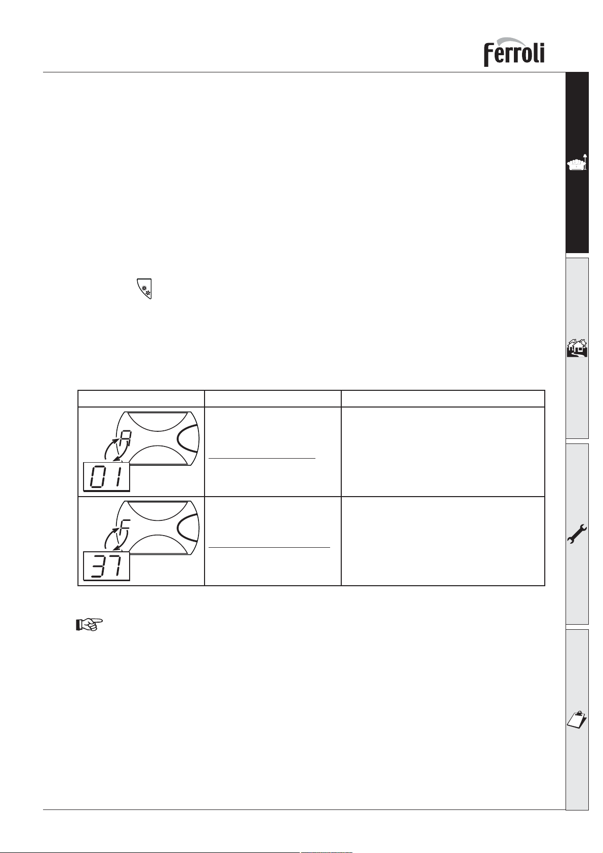
In the unlikely event of an operating problem, or component failure, the display flashes and a fault
identification code appears.
The boiler is equipped with an advanced self-diagnosis system that signals any faults on the display.
Some faults (“A“ indication) cause a boiler shutdown. In this case, operation must be reset manually by
pressing the
Other faults (“F“ indication) cause temporary shutdowns that are automatically reset as soon as the
value causing the fault comes back within the boiler’s normal working range.
Listed below are some anomalies that can be caused by simple, user-solvable problems.
If the problem remains after two attempts at resetting, contact the Ferroli Service Centre.
For other faults, refer to section 3.4 “Troubleshooting”.
reset
(Part. 6 – fig. 1) for 1 second.
Fault Cure
Make sure that the gas cocks ahead of the boiler
and on the meter are open.
No burner ignition
Low system pressure
Before calling a Ferroli service engineer, check that the problem is not due to there being no
gas or electricity, or low system pressure.
Press the RESET button (for 1 second).
In case of repeated shutdowns, contact the Ferroli
Service centre.
Fill the ‘system to 1-1.5 bar.
11
Page 12
2. INSTALLATION
2.1 General Instructions
This device must only be used for the purpose for which it is specially designed. This unit is
designed to heat water to a temperature below boiling point and must be connected to a heating system and/or a water supply system for domestic use, compatible with its performance,
characteristics and its heating capacity. Any other use is considered improper.
BOILER INSTALLATION MUST ONLY BE PERFORMED BY QUALIFIED PERSONNEL, IN ACCORDANCE
WITH ALL THE INSTRUCTIONS GIVEN IN THIS TECHNICAL MANUAL, THE PROVISIONS OF CURRENT
LAW, THE RECOMENDATION OF BS STANDARDS, ANY LOCAL REGULATIONS AND THE RULES OF
COMPETENT WORKMANSHIP.
IN IE, THE INSTALLATION MUST BE CARRIED OUT BY A COMPETENT PERSON IN ACCORDANCE
WITH THE CURRENT EDITION OF I.S. 813 “DOMESTIC GAS INSTALLATIONS”, THE CURRENT BUILDING REGULATIONS AND REFERENCE SHOULD BE MADE TO THE CURRENT ETCI RULES FOR
ELECTRICAL INSTALLATIONS.
Incorrect installation can cause damage or physical injury for which the manufacturer declines any
responsibility.
OPTIMAX HE 31 C
This appliance must be installed strictly in accordance with these instructions and
regulations:
The Gas Safety Regulations (Installations & Use).
The Local Building Regulations.
The Building Regulations (Part L).
The Buildings Standards (Scotland - Consolidated) Regulations.
British Standards Codes of Practice:
B.S. 5440 Part 1 Flues
B.S. 5440 Part 2 Air supply
B.S. 5449 FORCED CIRCULATION HOT WATER SYSTEMS
B.S. 6798 INSTALLATION OF GAS FIRED HOT WATER BOILERS
B.S. 6891 GAS INSTALLATIONS
B.S. 7671 IEE WIRING REGULATIONS
B.S. 4814 SPECIFICATION FOR EXPANSION VESSELS
B.S. 5482 INSTALLATION OF LPG
B.S. 7593 TREATMENT OF WATER IN DOMESTIC HOT WATER CENTRAL HEATING SYSTEMS
B.S. 5546 INSTALLATION OF HOT WATER SUPPLIES FOR DOMESTIC PURPOSES
I.S. 813 DOMESTIC GAS INSTALLATIONS (EIRE ONLY)
Model Water Bye Laws
B.S. 5955-8 PLASTIC PIPEWORK INSTALLATION
12
For Northern Ireland the rules in force apply
Page 13
OPTIMAX HE 31 C
2.2 Boiler location
The unit’s combustion circuit is sealed off from
the installation room and therefore requires no
compartment ventilation.
The installation room must be sufficiently well
ventilated to prevent any dangerous conditions from forming in the event of even slight
gas leakage. This safety standard is required
by the EEC Directive no. 90/396 for all gas
units, including those with a so-called sealed
chamber.
Therefore the place of installation must be
free of dust, flammable materials or objects
or corrosive gases. The room must be dry and
not subject to freezing.
The boiler is designed to be installed on a solid
wall. The wall fixing must ensure a stable and
effective support for the appliance, using the
bracket and fixings supplied.
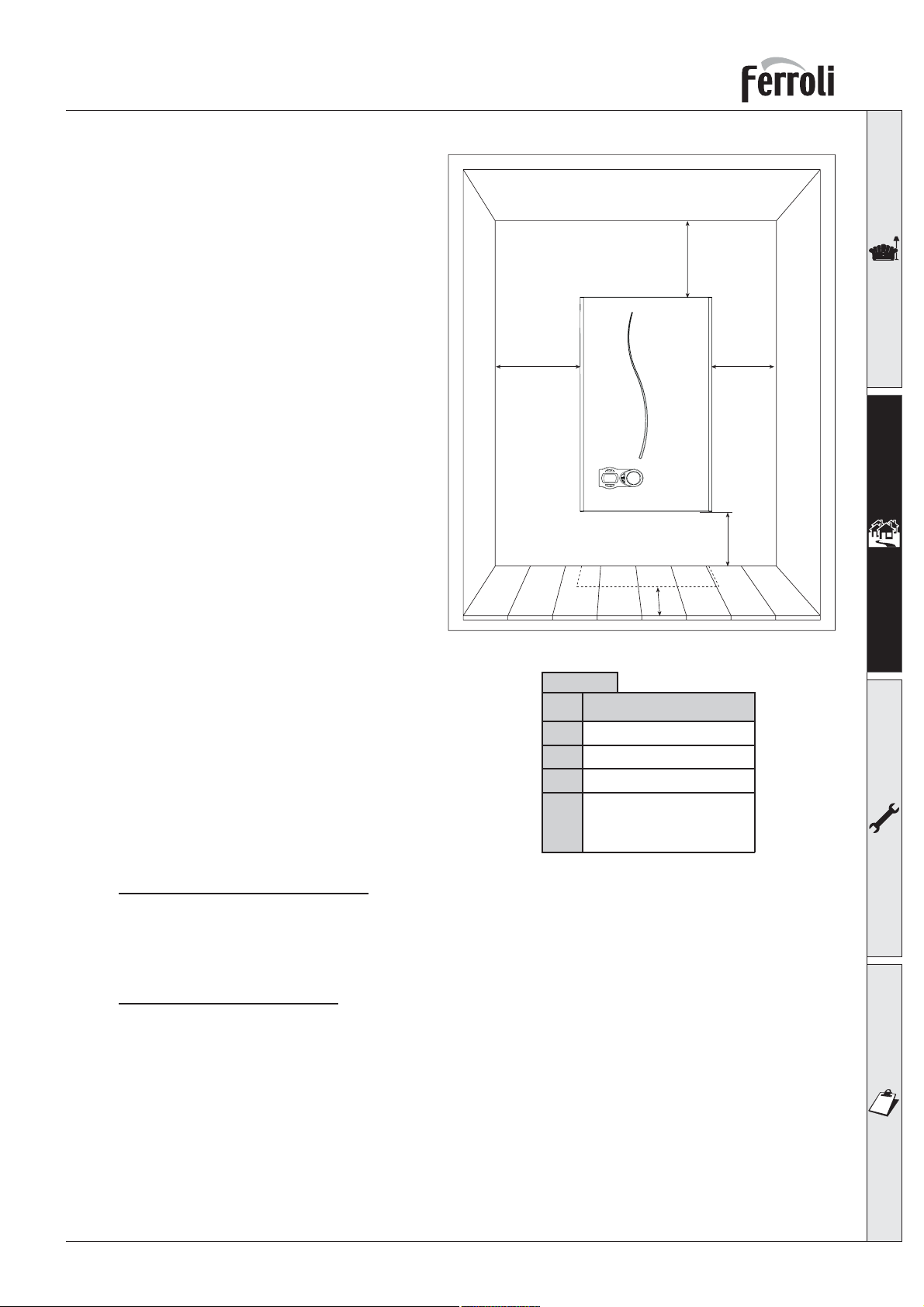
If the unit is enclosed in a cupboard or mounted alongside, there must be space for normal
maintenance work. Fig. 15 and tab. 1 gives the
minimum clearances to leave around the unit.
C
A A
B
D
fig. 15
Table 1
Minimum
A
2,5 cm
B
20 cm
C 30 cm
60 cm
D
(via an openable panel)
Safe Handling of Substances
Care should be taken when handling the boiler
insulation panels, which can cause irritation to the skin. No asbestos, mercury or CFCs are included in
any part of the boiler.
Product Handling Advise
When handling or lifting always use safe techniques - keep your back straight, bend your knees, don’t
twist - move your feet, avoid bending forwards and sideways and keep the load as close to your body
as possible.
Where possible transport the boiler using a sack truck or other suitable trolley.
Always grip the boiler firmly, and before lifting feel where the weight is concentrated to establish the
centre of gravity, repositioning yourself as necessary.
13
Page 14
OPTIMAX HE 31 C
2.3 Boiler water connections
The heating capacity of the unit should be previously established by calculating the building’s heat requirement according to current regulations. For good operation and long life of the boiler, the plumbing
system must be well proportioned and always complete with all those accessories that guarantee regular
operation and running, room thermostat, trv’s etc. The flow and return must be a minimum diameter of
22 mm for the first 3 metres from the appliance.
If the flow and return pipes follow a path where air pockets could form in certain places, it is essential to
install vent valves at these points. Also, install type “A” drain cocks at the lowest points in the system
to allow complete draining.
The temperature differential between the flow manifold and the return to the boiler should not exceed
20° C.
A minimum flow of 6 litres/min is required through the heat exchanger. An automatic by-pass is fitted
to the boiler which will provide this flow rate in most circumstances.
Do not use the water system pipes to earth electrical
appliances.
Before installation, carefully flush all the pipes of the heating
system to remove residues or impurities that could affect the
unit’s operation (BS 7593 Building regs Doc L).
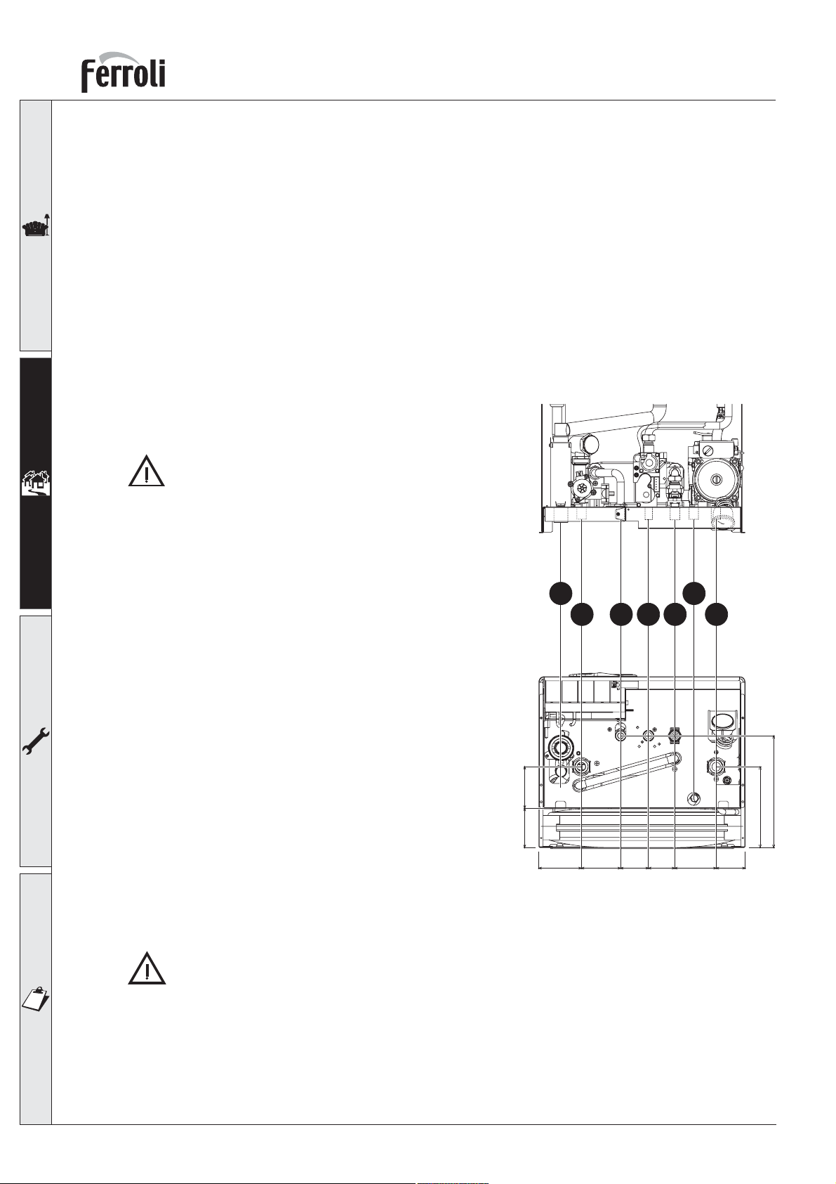
Make the connections to the appliance as shown in fig. 16
Key
1 System flow (22 mm with isolation valve fitted)
2 DHW outlet (15 mm )
3 Gas inlet (22 mm with isolation valve fitted)
4 Cold main inlet (15 mm with isolation valve fitted)
5 System return - 22 mm with isolation valve fitted (c/w filter)
6 Pressure Relief Valve
7 Condense outlet
It is essential to install the isolation valves supplied between the boiler and heating system, allowing the
boiler to be isolated from the system if necessary.
The safety valve outlet must be connected to a 15mm diameter copper pipe, with a continual
fall from the boiler to allow system water out onto the ground in the event of over-pressure in
the heating circuit. If this is not done, and the drain valve trips and floods the room, the boiler
manufacturer is not to be held responsible. The outlet should face back against the outer brickwork or building face to prevent harm or injury from hot water discharging in the event of an
over-pressurised system.
Make the boiler connection in such a way that its internal pipes are free of stress. If a check valve is
installed on the tap water circuit (where applicable), it is necessary to mount a safety valve between the
boiler and this circuit (check valve minimum 3 metres from boiler) or a domestic expansion vessel.
7 6
1 2 3 5
76,2 80,5
82,5 76 54 51 80,5 56
fig. 16
4
216,7
156,7
14
Page 15
OPTIMAX HE 31 C
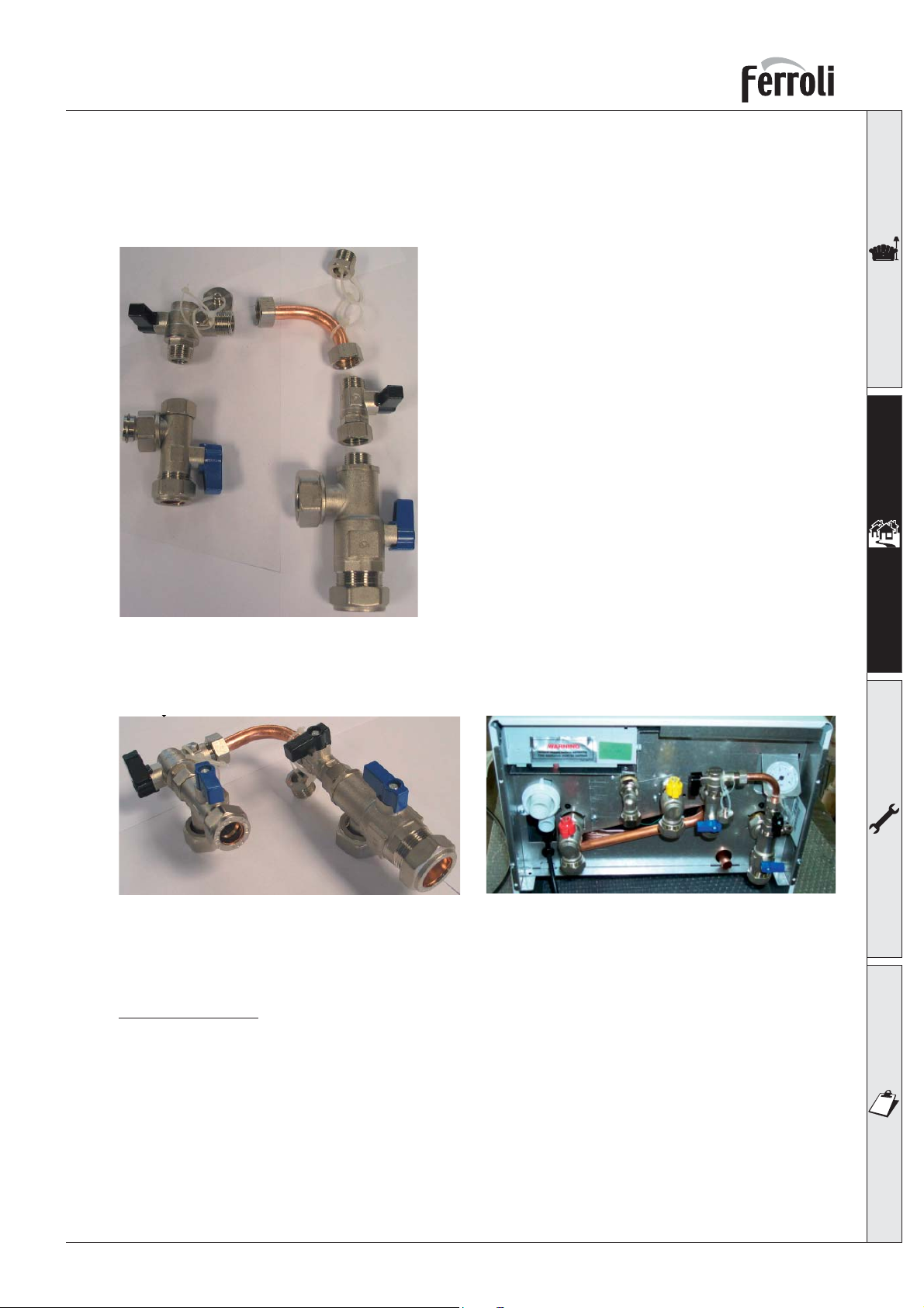
The isolation valves and filling kit shown in Fig. 17 is supplied as standard.
1 - The kit consist of the following items shown in fig 17.
&&&&
((((
''''
%%%%
$$$$
))))
Key
A Cold water inlet valve
B Double check valve
C Blanking cap
D Removable connection
E Blanking plug
F Isolation valve
G C/H return valve & filter
****
fig. 17
2 - Connect the items together as shown in fig. 18. 3 - .....and then connect the completed assembly
to the boiler as shown in fig. 19.
fig. 18 fig. 19
Make Up Water
Provision must be made for replacing water lost from the sealed system. Reference should be made
to BS6798, for methods of filling and making up sealed systems. There must be no direct connection
between the boiler's central heating system and the mains water supply. The use of mains water to
charge and pressurise the system directly, is conditional upon the Local Water Byelaws. Again any such
connection must be disconnected after use.
A filling connection is supplied with the valve set in the boiler box.
Attention - is drawn to the Model Water Byelaws.
15
Page 16
OPTIMAX HE 31 C
Water treatment
If treatment is used ferroli limited recommanded only the use of Fernox or Sentinel water treatment
products, which must be used in accordance with the manufacturers instructions. for further information
contact:
Fernox Manufacturing Co. LTD. Sentinel Performance Solutions Ltd
Cookson Electronics, Forsyth Road The Heath Business & Technical Park
Sheerwater, Woking, surrey, GU21 5RZ Runcorn, Cheshire WA7 4QX
Tel: 0870 8700362 Tel: 0151 424 5351
Note - If the boiler is installed in an existing system any unsuitable additives must be removed by thorough cleansing. All systems should be cleansed according to B.S. 7593.
Note - In hard water areas treatment to prevent lime scale may be necessary.
Note - It is important that the correct concentration of the water treatment product is maintained in
accordance with the manufacturers instructions.
2.4 Connection to the gas system
If necessary the local Gas supplier should be consulted, at the installation planning stage, in order to
establish the availability of an adequate supply of gas.
An existing service pipe must not be used without prior consultation with the local Gas supplier.
A gas meter can only be connected by the Local Gas supplier, or by a Local Gas suppliers Contractor.
Installation pipes should be fitted in accordance with BS6891.
Appliance inlet working pressure must be 20mbar MINIMUM, for NG and 37 mbar minimum for LPG.
Do not use pipes of a smaller size than the combination boiler inlet gas connection (22 mm).
The complete installation must be tested for gas soundness and purged as described in BS689. All
pipework must be adquately supported. An isolating gas valve is provided and should be fitted on
the boiler gas inlet. Please wait 10 minutes when lighting from cold before checking. Gas pressures
should be checked after the boiler has operated for 10 minutes to reach thermal equilibrium. This
appliance has no facility to check the burner pressure, however if the inlet pressure and the gas
rate are correct the boiler should be set correctly, the gas valve is set and sealed at the factory
and should not be adjusted without authorisation from Ferroli Personnel. A combustion test can
be carried out to ensure correct air/gas mix (see page 29 combustion analyser testing).
The isolation kit shown in Fig. 17 is supplied as standard.
2.5 Electrical Connections
The unit must be installed in conformity with current national and local regulations.
Connection to the electrical supply
The boiler must be connected to a single-phase, 230 Volt-50 Hz electric supply.
The unit’s electrical safety is only guaranteed when correctly connected to an efficient earthing
system installed according to current safety standards. Have the efficiency and suitability of the
earthing system checked by professionally qualified personnel. The manufacturer is not responsible
for any damage caused by failure to earth the system. Also make sure that the electrical system
is adequate for the maximum power absorbed by the unit, as specified on the boiler dataplate,
in particular ensuring that the cross sectional area of the system’s cables is suitable for the power
absorbed by the unit.
The boiler is prewired and provided with a cable and fitted with a 3 amp fused plug for connection to
the electricity supply. It is important to respect the polarities (LIVE: brown wire / NEUTRAL: blue wire
/ EARTH: yellow-green wire) in making connections to the electrical supply.
16
Page 17
OPTIMAX HE 31 C
The user must never change the unit’s power cable. If the cable gets damaged, switch off the unit
and have it changed only by professionally qualified personnel. If changing the electric power cable,
use only “HAR H05 VV-F” 3x0.75 mm2 cable with a maximum outside diameter of 8 mm.
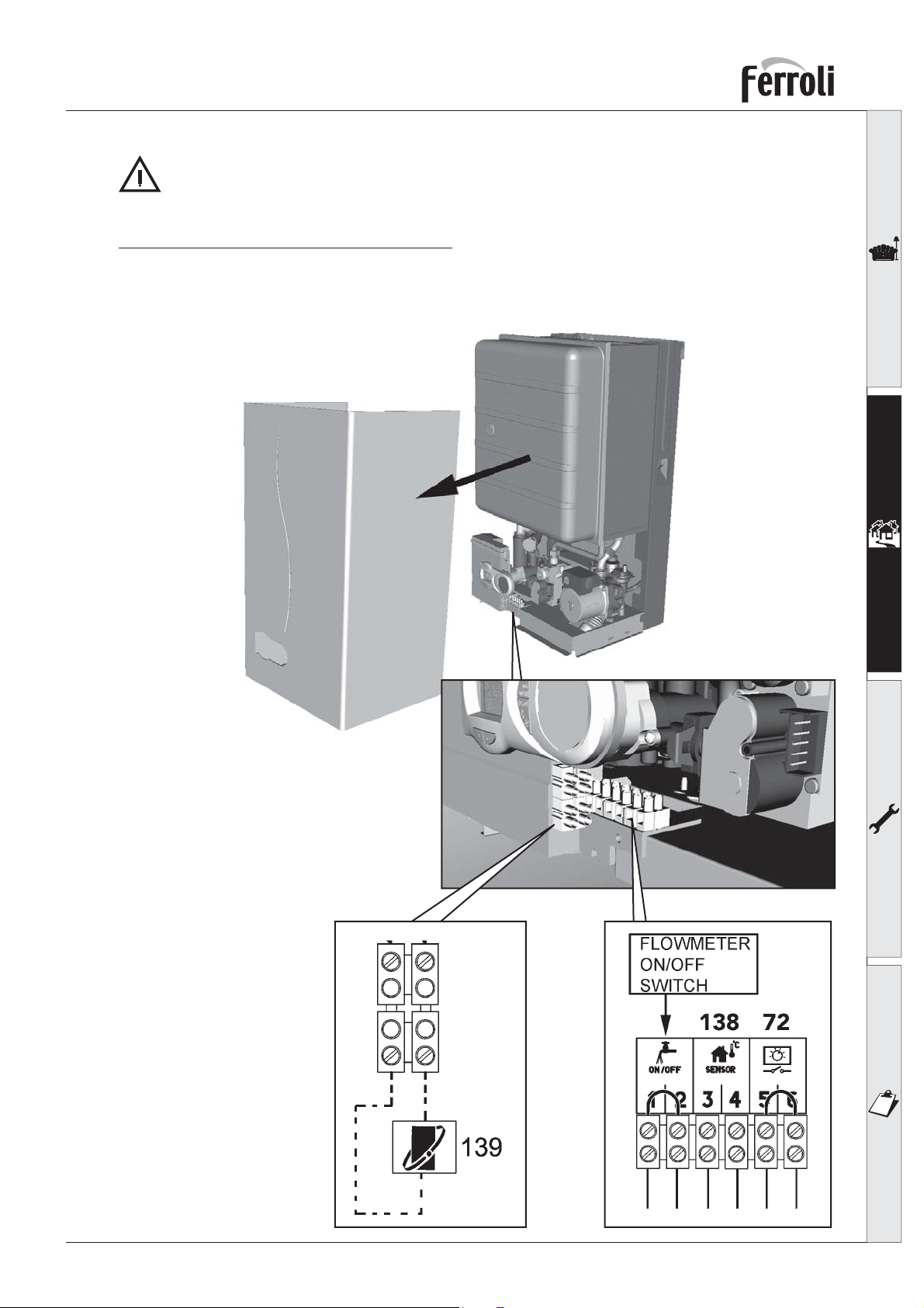
Access to the electrical terminal block
Follow the instructions given in fig. 20 to access the electrical connection terminal board. The layout of
the terminals for the various connections is given in the wiring diagram in the Technical Data chapter.
Key
72 Room thermostat (Volt Free)
138 Outside temperature sensor
139 Room unit (OpenTherm)
fig. 20
fig. 21
17
Page 18
OPTIMAX HE 31 C
Room thermostat
CAUTION: THE ROOM THERMOSTAT MUST HAVE VOLTAGE FREE CONTACTS. CONNECTING
230 V. TO THE TERMINALS OF THE TIME CLOCK AND ROOM THERMOSTAT WILL IRREPARA-
BLY DAMAGE THE P.C.B.
2.6 Flue system
The unit is “type C” with a sealed chamber and forced draught, the air inlet and flue outlet must be
connected to one of the following flue systems. With the aid of the tables and methods of calculation indicated, before commencing installation, it is first necessary to check that the flue system does not exceed
the maximum permissible length. The current standards and local regulations must be observed.
It should be noted that only Ferroli flue system and accessories should be used on this appliance,
as per BS 5440 2000 and C.E. test certification.
18
Page 19
OPTIMAX HE 31 C
Connection with concentric flue system
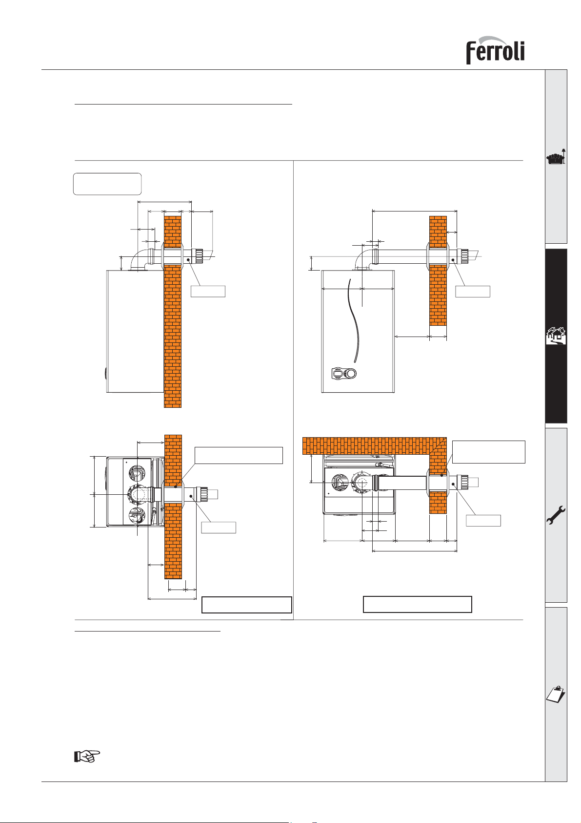
The unit can be connected to a concentric air/flue duct with a horizontal or vertical outlet as shown on
the following drawings. Numerous accessories are available on request to meet the various installation
requirements. Please refer to our “flue manual” or the price list.
Standard concentric flue installation
Standard 1KWMA53A
Flue kit
80
Rear Outlet
Side view
P
96
S
95
30
View from above
156
50*
125
* = between
10 e 60 mm
Install level
Drill the wall 10÷20 mm
more than the pipe diameter
80
156
30
95
215 185
View from above
Side Outlet
Front view
L
DS
50*
* = between
10 e 60 mm
Install level
Drill the wall 10÷20 mm
more than the
pipe diameter
185215
fig. 22a
110
S 50*
P
Install level
P = S + 146 mm
fig. 22b
30
95
215 185
L = S + D + 170 mm
DS50*
L
Install level
Horizontal flue installation
1. Define the position for installing the unit.
2. If using standard flue (1KWMA53A) this must be installed level, for non-standard flue lengths over
1mtr a fall of 3 mm back to the boiler per metre should be incorporated.
3. Make a hole of diameter 10 - 20 mm greater than the nominal diameter of the concentric pipe
used.
4. If necessary, cut the terminal length to size, ensuring that the external pipe protrudes from the wall
by between 10 and 60 mm (fig. 22a and 22b). Remove the cutting burrs.
5. Connect the flue to the boiler, positioning the seals correctly. Seal the flue into the wall with silicone
or sand + cement and cover with wall seals provided.
Flue seals should be lubricated with a silicone type grease to prevent damage (grease not supplied)
19
Page 20
OPTIMAX HE 31 C
Vertical Outlet
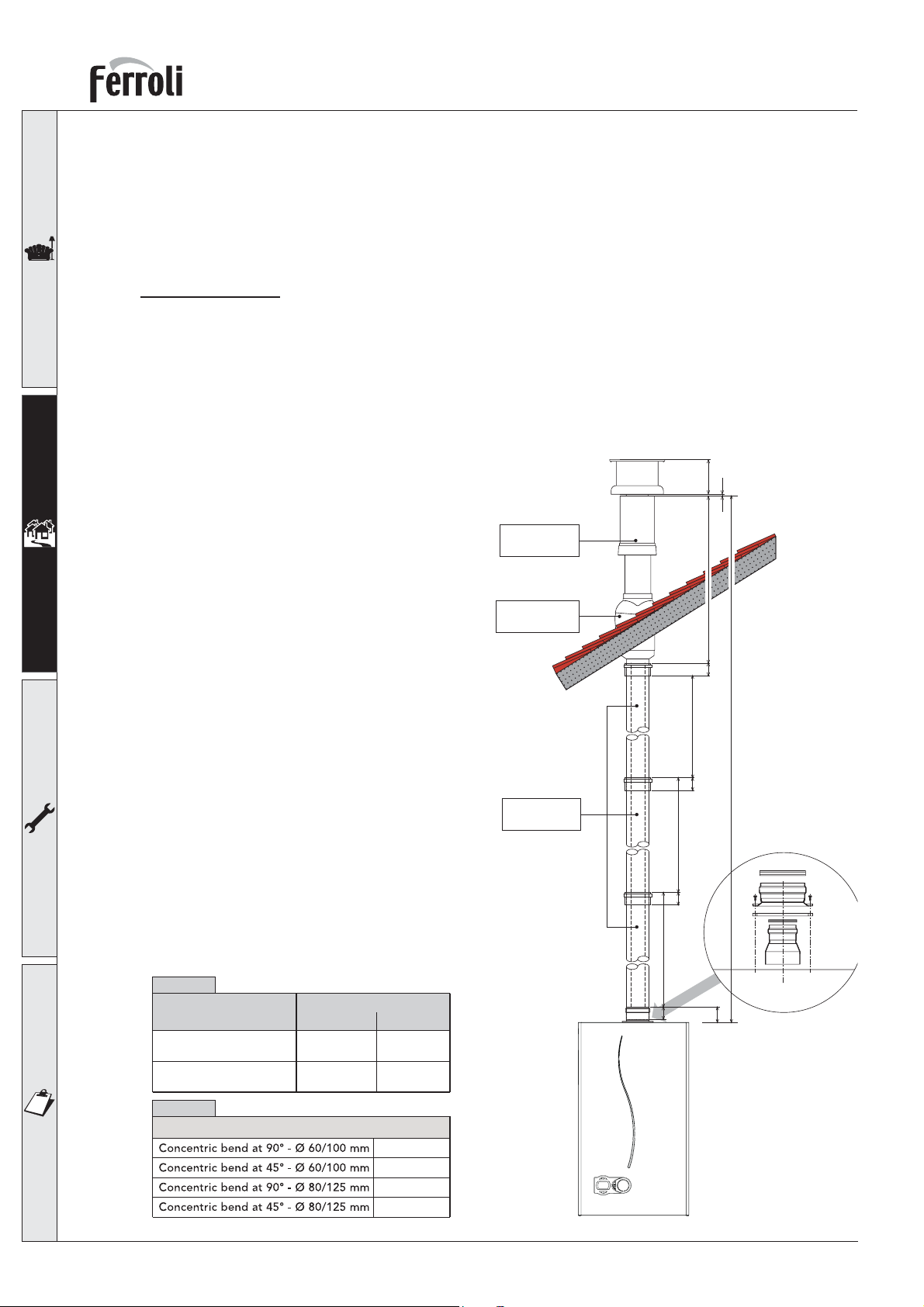
The total length in equivalent metres of the concentric flue must not exceed the maximum lengths stated
in the following table, note that each bend gives rise to the stated reduction. For example, a duct = 60/100
composed of 1 bend of 90° +1 horizontal metre + 2 bends of 45° + 1 horizontal metre has a total equivalent
length of 4 metres.
Vertical flueing
The installation of a concentric vertical flue can be carried out as follows,
Install the appliance as previously mentioned in this manual.
1. Connect onto the flue assembly at the top of the appliance a concentric vertical adaptor part number
1KWMA71W,
2. Use the required amount of 1mtr flue extensions (part number 1KWMA56U) inserting them spigot
down ensuring the seals are well lubricated with silicone grease (not supplied) and correctly located
into the sockets.
3. If required 45° bends (Part number1KWMA64A)
may be used with a resistance value of 0.5mtrs
1000 125
50
950
50
10
max. 6 mt 60/100
max. 16 mt 80/125
each, the flue should be routed in such away
to avoid any unnecessary deviation and thus
minimise the amount of bends required.
4. The termination should be made through our
concentric flue outlet (part number 1KWMA83U)
in conjunction with a roof slate pitched (part
number 1KWMA82U) or flat roof (part number
1KWMA81U) The storm collar must be fixed on
using the three screws provided and sealed with
an external grade silicone (not supplied).
5. For longer flue lengths a 125mm concentric flue
system is available.
6. All flue installations must comply with BS5440
part 1 and must only be of Fèrroli manufacture.
The vertical flue must continually rise and be
supported throughout its length. The flue must
be inspected whilst commissioning the appliance
to ensure it is sound throughout its length.
Vertical Terminal
1KWMA83U
Pitched roof slate
1KWMA82U
1KWMA56U
20
This information is for guidance purposes and Fèrroli will in no way be held responsible for incorrect
installation following this guide.
Table 2a
Maximum permissible
duct length (Horizontal)
Maximum permissible
duct length (Vertical)
Table 2b
Reduction factors for bends
Ø mm
60/100
5 m 15 m
6 m 16 m
Ø mm
80/125
1 m
0,5 m
0,5 m
0,25 m
1KWMA71W
50 950
95050
68
fig. 22c
Page 21
OPTIMAX HE 31 C
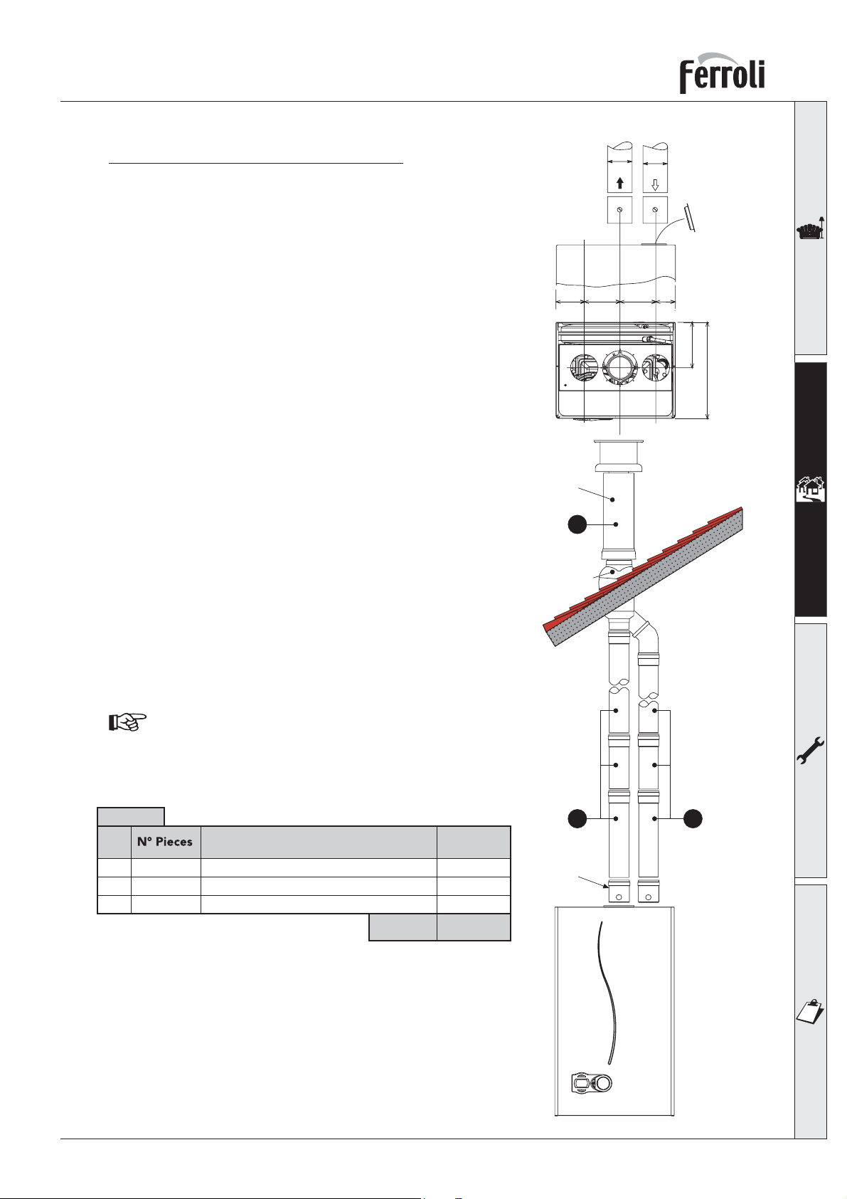
Connection with 80 mm pipe system
The unit can be connected to a system of separate air/flue
pipes for a horizontal or vertical outlet as shown fig 23 - 24
. Numerous accessories are available on request to meet
the various installation requirements. The components
used most frequently are stated in tables 4 - 5. Please
refer to the flue manual or the price list for additional
components.
To check you do not exceed the maximum permissible
flue length, it is necessary to make a simple calculation
before installation:
1KWMR54A
95
120
Ø80
FLUE
120
Ø80
AIR
Remove
the closing
cap
65
156
1. For each component, tables 4 - 5 provide an “equivalent loss in linear metres”, depending on the position
of installation of the component (with air intake or flue
extraction, vertical or horizontal).
The loss is called “equivalent length” since it is compared
to the loss of one metre of flue (defined as equal to 1).
For example, a bend at 90° of Ø80 in flue extraction has
an equivalent loss of 2 linear metres, i.e. it has a loss
equal to that of 2 linear metres of flue length.
2. After completely defining the layout of the system of twin
flues, add up the losses in equivalent metres, depending
on the installation position, of all the components and
accessories in the system.
3. Check that the total calculated loss is less than or equal
to 75 equivalent metres, i.e. the maximum permissible
for this model of boiler.
For complete flue options please contact ferroli or
check our comprehensive flue manual.
330
fig. 23
1KWMA84U
5
1KWMA82U
Table 3
Ref.
2
4
5
23
23
1KWMA83W
4
Description
Vertical air pipe Ø80
Vertical flue pipe Ø80
1
80 Ø vertical flue Kit
Total
Equivalent
loss
23,0 m
36,8 m
12,0 m
71,8 m
1KWMR54A
2
fig. 24
21
Page 22
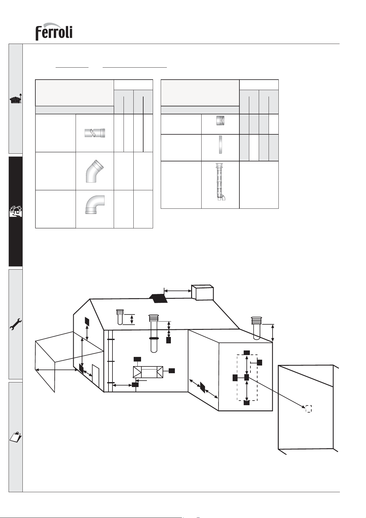
Table of Ø80 flue and accessory
Table 4 Table 5
Equivalent losses in
metres (linear)
Accessories Ø 80 Accessories Ø 80
Air Flue
OPTIMAX HE 31 C
Equivalent losses in
metres (linear)
Air Flue
Description
Pipe Ø 80
male-female
1KWMA83W 1,00 m
Bend 45° Ø 80 mm
male - female
Bend 90° Ø 80 mm
male - female
Terminal Position
1KWMA65W
1KWMA01W
Vertical
Horizontal
Vertical
1 1 1.6 2
1.2 1.8
1.5 2.0
Horizontal
terminal
Description
1KWMA86A
1KWMA85A
1KWMA84U
Vertical
Horizontal
Vertical
Horizontal
5
2
12
Horizontal
Horizontal
flue terminal
air terminal
Vertical flue
The stated loss values refer to genuine Ferroli flue accessories.
P
Q
l
Q
D, E
Q
F
J
L
B
G
C
A
H
N
MM
N
H
K
fig. 25
22
Page 23
OPTIMAX HE 31 C
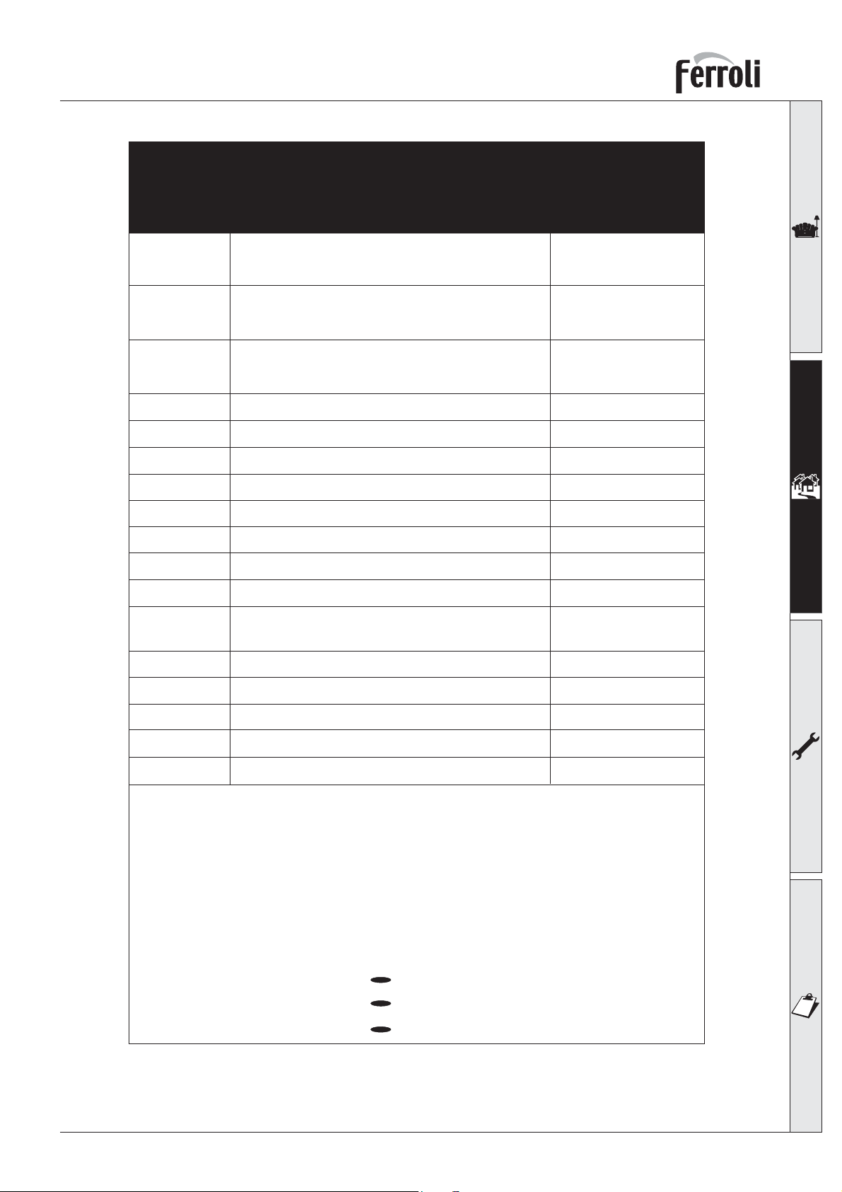
Minimum Dimensions of Flue Terminal Positions
A
B
C
D
E
F
G
H
I
J
K
L
Directly below an opening, air brick,
opening windows, etc.
Above an opening, air brick,
opening windows, etc.
Horizontally to an opening, air brick,
opening windows, etc.
Below gutters, soil pipes or drain pipes
Below eaves
Below balconies or car port roof
From a vertical drain pipe or soil pipe
From an internal or external corner
Above ground roof or balcony level
From a surface facing the terminal
From a terminal facing the terminal
From an opening in the car port (e.g. door,
window) into the dwelling
300mm
300mm
300mm
75mm
200mm
200mm
150mm
100mm
300mm
600mm
1200mm
1200mm
M
N
O
P
Q
NOTE
N/A = Not applicable
In addition, the terminal should not be nearer than 150mm (fanned draught)
to an opening in the building fabric formed for the purpose
of accommodating a built-in element such as a window frame.
Condensing Terminal Positions: If the flue is to be terminated at low level, then the
potential effect of the plume must be considered.
Plume management kits are available from Ferroli.
The plume should not be directed:
Vertically from a terminal on the same wall
Horizontally from a terminal on the same wall
From the wall on which the terminal is mounted
From a vertical structure on the roof
Above intersection with roof
across a frequently used access route
towards a window or door
across a neighbouring property
1500mm
300mm
N/A
150mm
300mm
23
Page 24
OPTIMAX HE 31 C
Connection to collective flues or single flues with natural draught
If you are then going to connect the OPTIMAX HE 31 C boiler to a collective flue or a single flue with
natural draught, the flue must be expressly designed by professionally qualified technical personnel in
conformity with the standards and rules in force.
In particular, flues must have the following characteristics:
• Be sized according to the method of calculation stated in the standard
• Be airtight to the products of combustion, resistant to the fumes and heat and waterproof for the
condensate
• Have a circular or square cross-section (some hydraulically equivalent sections are permissible), with
a vertical progression and with no constrictions
• Have the flue conveying the hot fumes adequately distanced or isolated from combustible materials
• Be connected to just one unit per floor, for at most 6 units in all (8 if there is a compensation duct or
opening)
• Have no mechanical suction devices in the main ducts
• Be at a lower pressure, all along their length, under conditions of stationary operation
• Have at their base a collection chamber for solid materials or condensation of at least 0.5 m, equipped
with a metal door with an airtight closure.
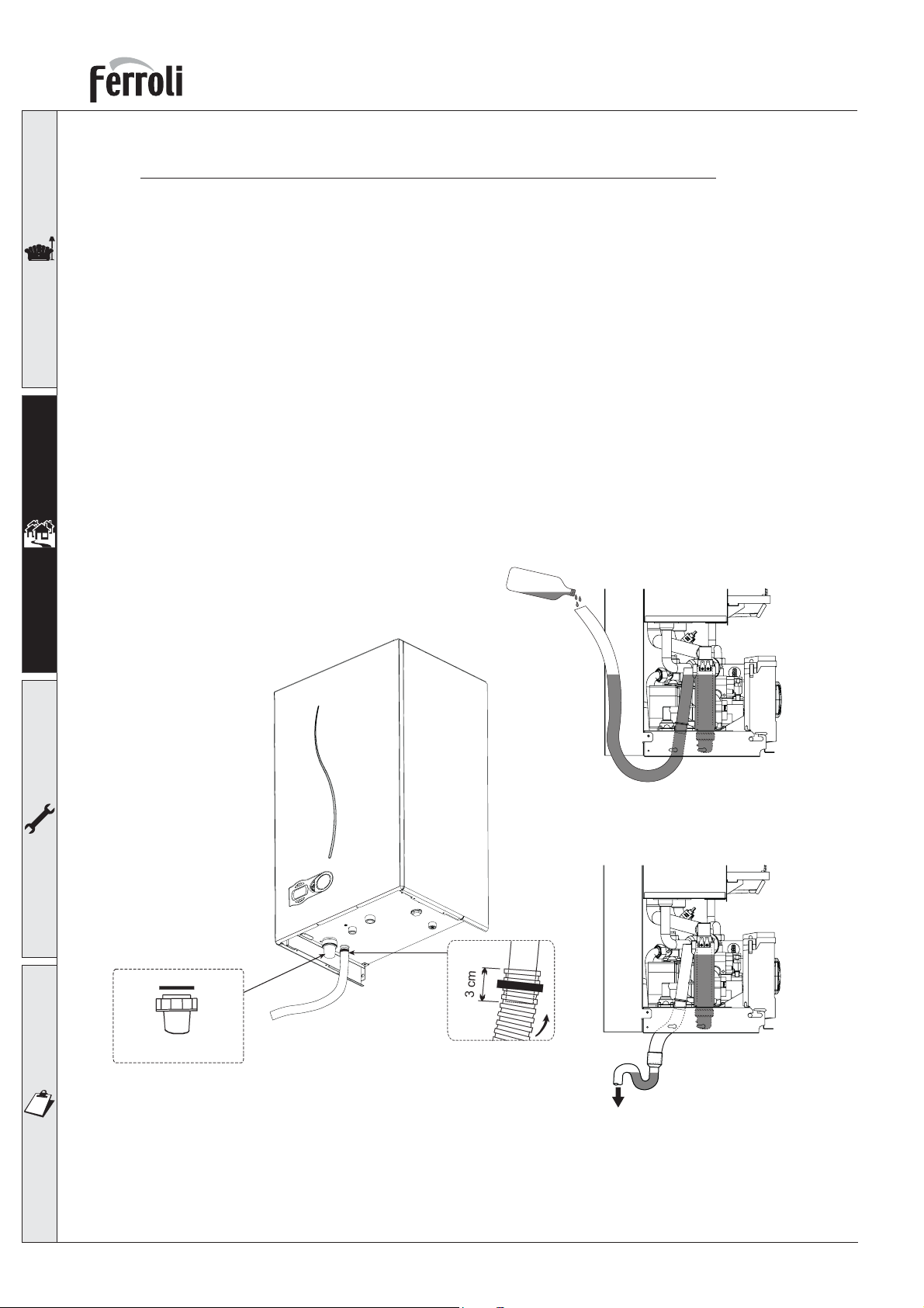
2.7 Condensate outlet connection
B
A
0,5 lt.
24
fig. 26
The boiler is equipped with an internal air-trap to drain off the condensate. Fit the inspection coupling
A and the hose B, pushing it on for approximately 3 cm and securing it with a clamp.
Fill the air-trap with approximately 0.5 ltrs of water and connect the hose to the waste system, or
soakaway.
Page 25
OPTIMAX HE 31 C
Condensate discharge
Where possible the condensate should discharge into an internal soil pipe or waste system. The minimum
pipe diameter required is 22 mm, a trap has already been fitted to the appliance with a flexible tail to
facilitate the connection to the condensate discharge pipe.
The pipe should be a solvent weld plastic, not copper, as the condensate has a ph value of 4 (slightly
acidic).
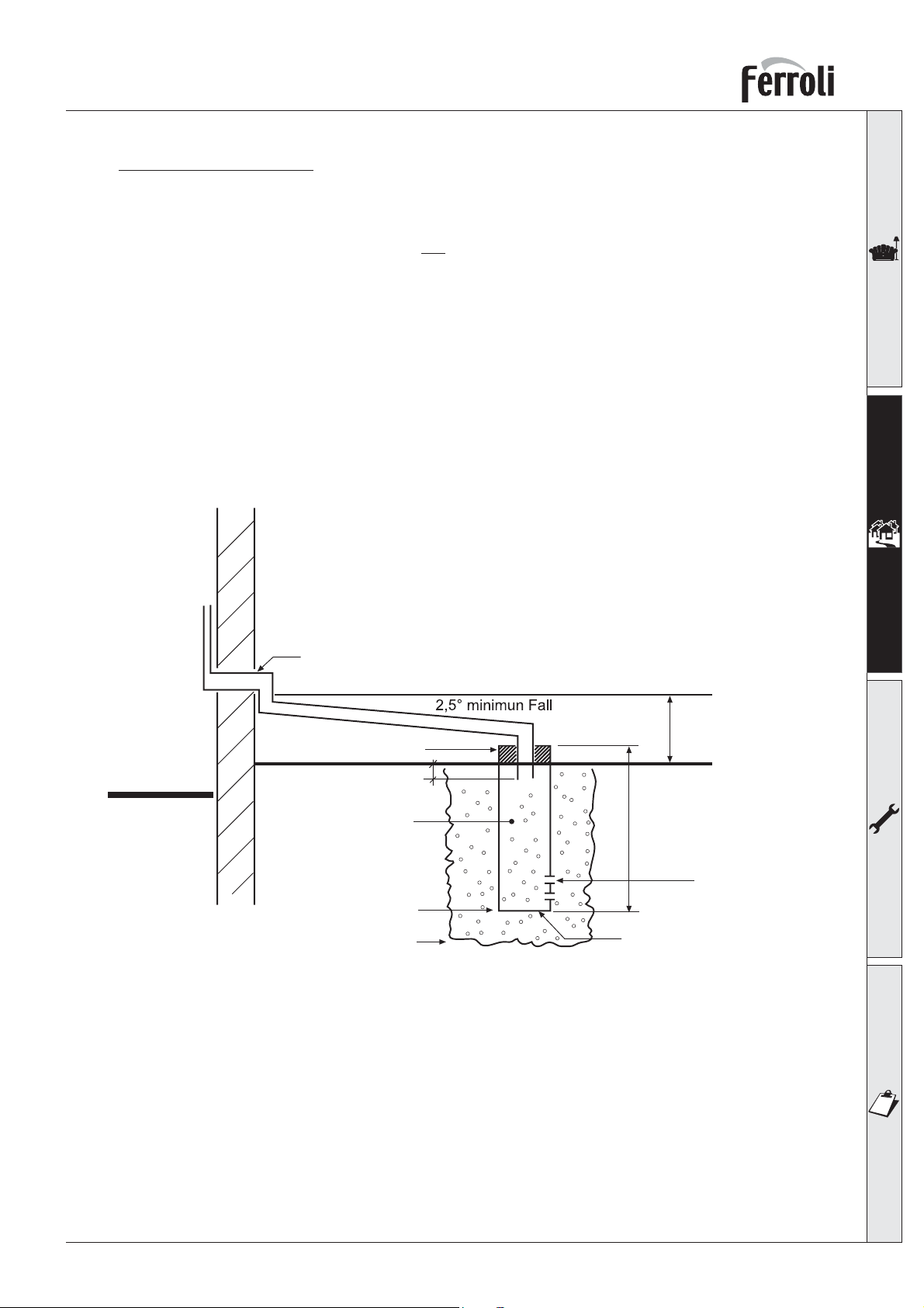
Where it is not possible to terminate internally, the condensate discharge pipe may be run outside (see
below drawing).
Any external run is subject to freezing, in severe weather conditions. To avoid this the pipework should
be installed to dispose of the condensate quickly, with as much as possible run internally, before passing
through the wall.
Pipework external to the building should be increased in diameter to 32 or 40 mm solvent weld. It should
be run to a external drain or soakaway, with a maximum length of 3 metres.
When a soakaway (condensate absorption point) is used, it should be constructed as shown below, or
use a specifically designed unit, for example Mc Alpine SOAK1GR available from most plumbing and
heating stockists.
Internal
External
32/40mm Solvent weld pipework 2.5 * Minimum Fall see below
Cement seal
25mm
100mm Dia tube
Lime stone chippings
Hole depth 400mm
Ground level (either/Or)
-300mm
2 Rows of
3x12 mm Holes
Bottom sealed
fig. 27
25
Page 26
OPTIMAX HE 31 C
3. SERVICE AND MAINTENANCE
3.1 Adjustments
All adjustment and conversion operations must be carried out by Qualified Personnel such as ferroli
Technical Service.
FERROLI declines any responsibility for damage or physical injury caused by unqualified and unauthorized
persons tampering with the device.
Gas supply conversion
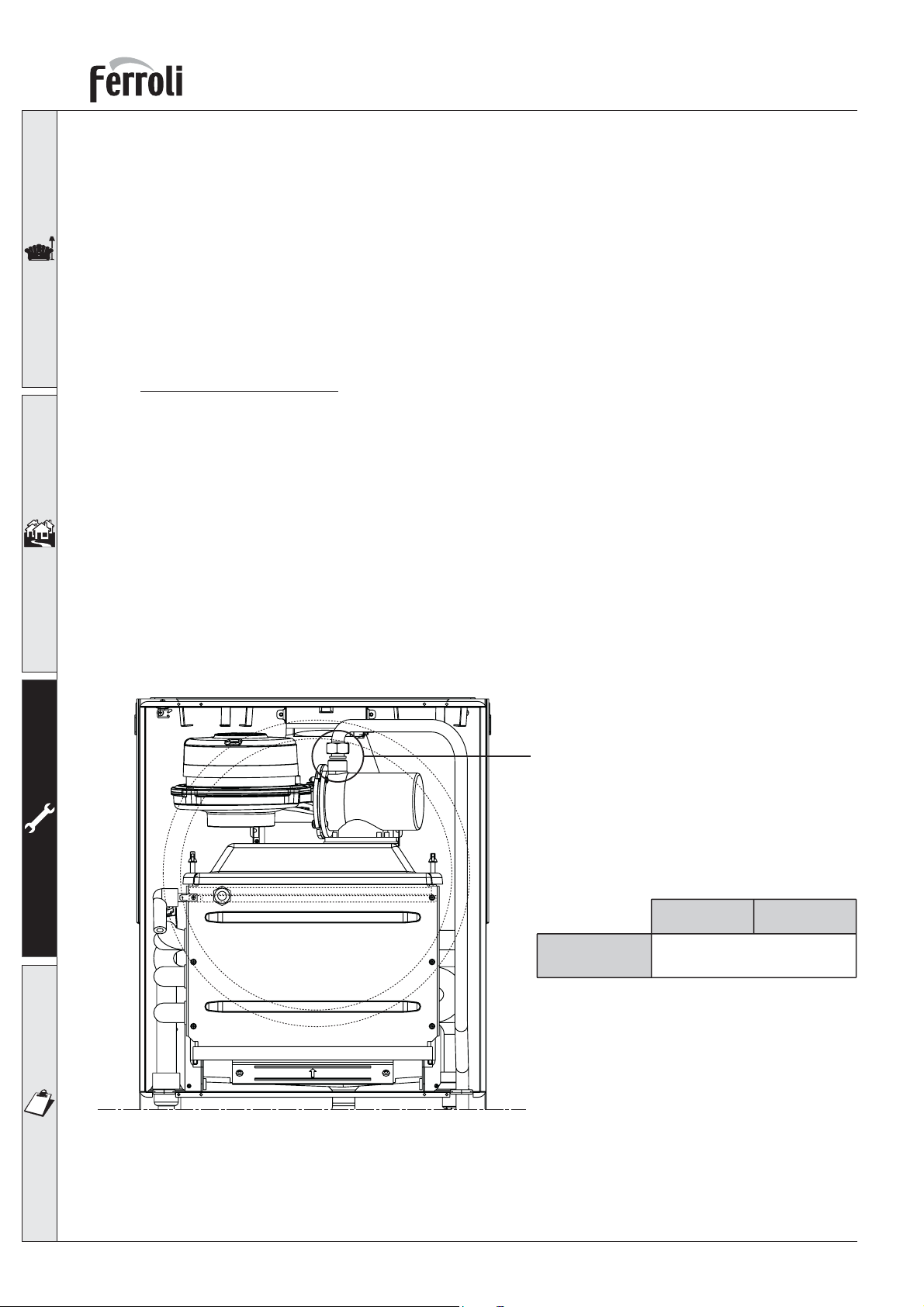
The unit can function with either Natural Gas or LPG and is factory-set for use with one of the two gases,
as clearly shown on the packing and on the unit’s dataplate. Whenever a different gas to that for which
the unit is preset has to be used, a conversion kit will be required, proceeding as follows:
1 Remove the casing.
2 Open the airtight chamber.
3 Unscrew the gas coupling A on the air/gas mixer.
4 Replace the injector in the mixer with the one contained in the conversion kit.
5 Refit the coupling A and check the connection is gastight.
6 Apply the sticker, contained in the conversion kit, near the dataplate.
7 Fit the airtight chamber and casing back on.
8 Check working pressure.
9 Check CO2 mixture as detailed (page 29 combustion analyser testing).
fig. 28
A
Injector Ø
Natural gas LPG
See technical data table
26
Page 27
OPTIMAX HE 31 C
3.2 System start-up
Commissioning must be performed by Qualified Personnel.
Checks to be made at first ignition, and after all maintenance operations that involved disconnecting from the systems or an intervention of a safety device.
Before lighting the boiler:
• Open any isolation valves between the boiler and the system.
• Check the tightness of the gas system, proceeding with caution and use gas leak detection fluid to
detect any leaks in connections.
• Fill the water system and make sure that all air contained in the boiler and the system has been vented
by opening the air vent valve on the boiler and any vent valves on the system.
• Make sure there are no water leaks in the system, hot water circuits, connections or boiler.
• Make sure the electrical system is properly connected.
• Make sure that the unit is connected to a good earthing system.
• Make sure there are no flammable liquids or materials in the immediate vicinity of the boiler.
• Vent and spin the pump.
• Ensure the flue system is correctly fitted, including terminal locations.
Ignition
• Open the gas valve upstream of the boiler.
• Purge the air from the installation pipework to the appliance.
• Switch on the boiler electrical supply.
• Press the key on the boiler for 5 seconds (part. 7 - fig. 1).
• The boiler is now ready to function automatically whenever there is a demand on the boiler.
In case of an electrical power failure while the boiler is working, the burner will go out. When
power returns, the boiler will run the self-test cycle again, after which the burner will automatically
re-ignite (if there is still a demand).
Checks during operation
• Check the tightness of the gas circuit and water systems.
• Check the efficiency of the flue and air-flue ducts while the boiler is working.
• Check that the water is circulating properly between the boiler and the system.
• Make sure that the gas valve modulates correctly.
• Check the proper ignition of the boiler by performing various tests, turning it on and off with the
room thermostat or remote control.
• Make sure that the gas rate indicated on the meter corresponds to that given in the technical data
table in section 4.4 page 35
Turning off
Press the key for 5 seconds (
part. 7 - fig. 1
).
27
Page 28
OPTIMAX HE 31 C
3.3 Maintenance
The following operations are strictly reserved for Qualified Personnel, such as corgi registered
engineers or Ferroli engineers.
Seasonal inspection of the boiler and flue
It is advisable to carry out the following checks at least once a year:
• The control and safety devices (gas valve, flow meter, thermostats, etc.) must function correctly.
• The flue terminal and ducts must be free of obstructions and leaks.
• The gas and water systems must be sound.
• The burner and exchanger must be clean.
• The electrodes must be free of deposits and correctly positioned.
• The system pressure when cold must be approx 1 bar; otherwise, bring it to that value.
• The expansion vessel must be filled to 1 bar cold with zero system pressure.
• The gas flow and pressure must correspond to that given in table 10 section 4.4 page 35.
• The circulating pump must be vented and free of debris.
• The return filter cleaned.
• The condensate trap inspection bowl should be cleaned and free of debris.
28
Page 29
OPTIMAX HE 31 C
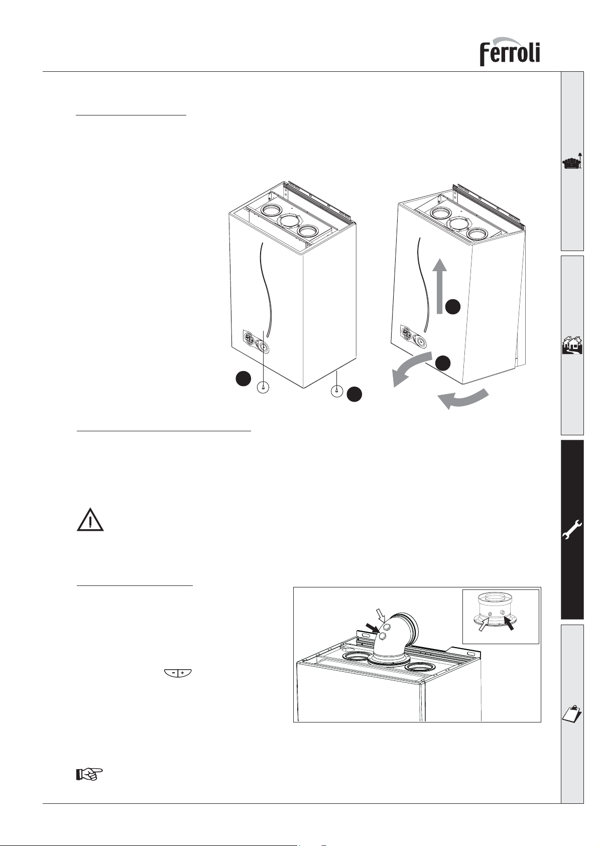
Opening the casing
To open the boiler casing, you need to follow the sequence given below
and the instructions of fig. 29.
1 Using a screwdriver, fully unscrew and remove the 2 screws “A ”
2 Open by lowering the panel “B ”
3 Lift and take off the casing “C ”
C
e
c
c
o
o
m
f
o
r
reset
t
2
1
0
e
c
c
o
o
m
f
o
r
res
t
et
2
1
0
3
B
A
R
4
3
B
A
R
4
B
fig. 29
A
A
Cleaning the boiler and burner
The body and burner must not be cleaned with chemical products or wire brushes. Special care must
be taken over all the sealing systems pertaining to the sealed chamber (gaskets, cable clamps, etc.). In
addition, it is necessary to pay attention after performing all these operations to check and carry out all
the phases of ignition and thermostat operation, the gas valve and circulation pump.
After these checks, make sure there are no gas leaks.
Combustion analysis
It is possible to analyse the combustion through
the air and flue sampling points shown in fig.
16.
To make the measurement, it is necessary to:
1) Open the flue sampling point
2) Insert the probe;
3) Press CH button (part. 3, 4 - fig. 1) for
5 seconds to turn on TEST mode;
4) Wait 10 minutes for the boiler to stabilize
5) Take the measurement.
Flue Gas
Air
Air
Flue Gas
NAT GAS; CO2 reading should be 8.7 to 9.0%
L.P.G; CO2 reading should be 9.5 to 10%
Readings taken with an unstabilized boiler will cause measurement errors.
fig. 30
29
Page 30
OPTIMAX HE 31 C
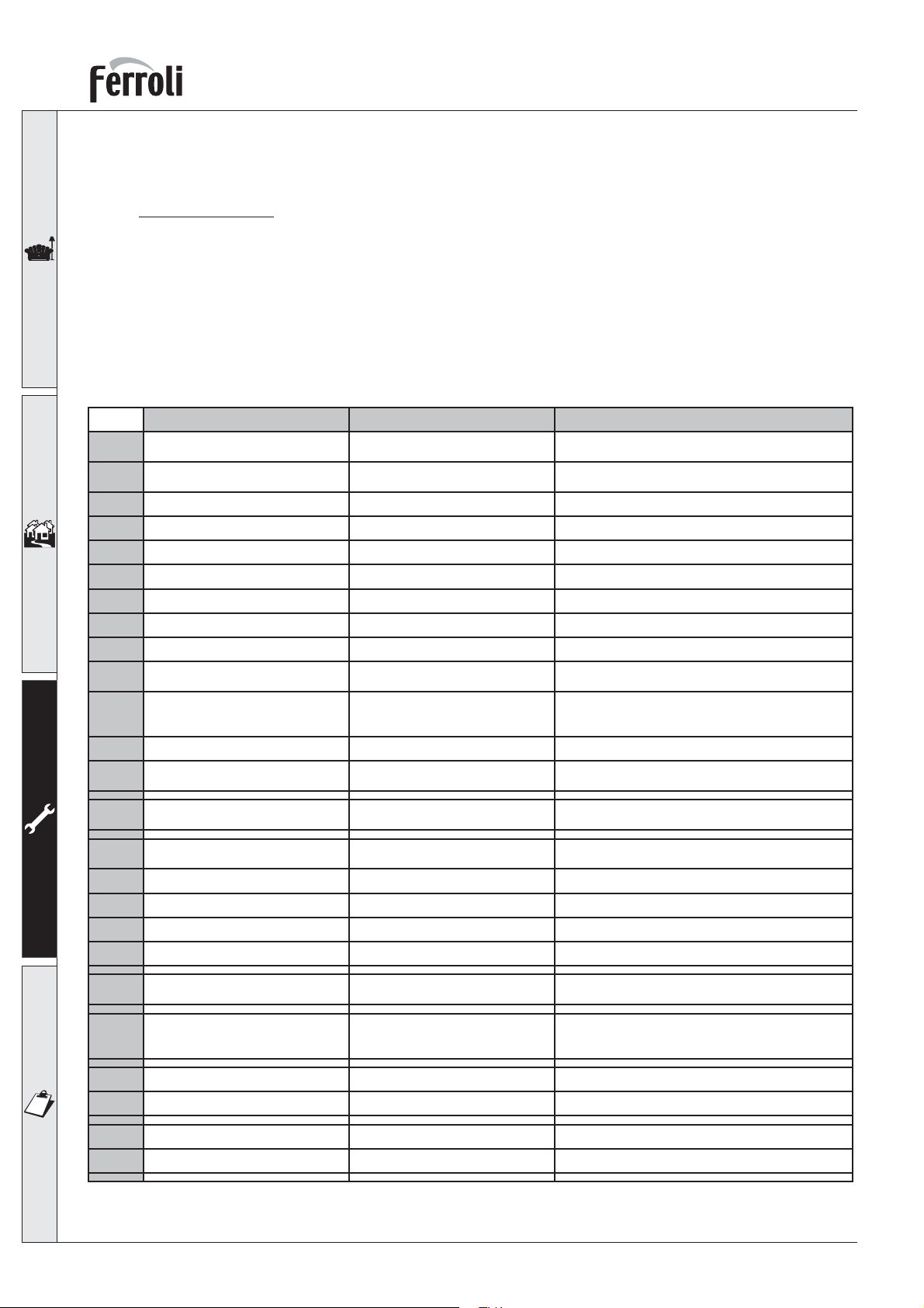
3.4 Troubleshooting
Fault Diagnosis
In the event of operating problems or trouble, the display will flash and a fault identification code
appears.
There are faults that in order to restore operation the RESET button must be pressed (ref.6 - fig. 1); or
if the boiler fails to start, it will be necessary to repair the fault (code nos. F1 to F24). Other faults cause
temporary shutdowns that are automatically reset as soon as the value comes back within the boiler’s
normal working range (codes from 25 to 47).
When the boiler starts functioning normally again, the display stops flashing and the fault code disappears.
Fault Possible cause Cure
No burner ignition No gas Check the regular gas fl ow to the boiler and the air
A01
Detection or ignition electrode fault Check that the electrodes are correctly positioned
Defective gas valve Check and change the gas valve
Incorrect inlet gas pressure Check inlet gas pressure
Siphon obstructed Check and if necessary change the siphon
has been purged from the pipes.
and free of any deposits
Flame detected with the burner off Ionisation electrode defective Check the ionizing electrode wiring
A02
High limit protection Flow temperature sensor not active
A03
Flue gas fault Fault F07 happened 3 times in the
A04
Fan problem Tachometer signal interrupted for 1
A05
No fl ame after the ignition phase (6
A06
times in 4 min.)
Flow sensor disconnected Sensor disconnected Check the correct position and operation of the fl ow
A41
Flue gas fault The exhaust gases temperature
F07
Flow sensor fault Sensor damaged or short circuited Check the wiring or change the sensor
F10
Main board defective Check the PCB
or correctly located
No system circulation Check the pump and radiator valves present in the
last 24 hours
hour or longer
Detection electrode fault Check that the electrode is correct positioned and if
Flame unstable Check the burner
Incorrect valve gas Offset Check Offset at the minimum power
Flue gas circuit obstructed Check if fl ue gas circuit is free
Siphon obstructed Check and if necessary change the siphon
becomes higher than 95°C for 2
minutes.
Sensor damaged or wiring broken Check the wiring or change the sensor
Check the correct positioning and operation of the
fl ow sensor
system
Check operation of the internal by-pass
Check the fl ue
Check the wiring and the fan
necessary change it
sensor
Check the fl ue
30
Return sensor fault Sensor damaged or wiring shorted Check the wiring or change the sensor
F11
Sensor damaged or wiring broken Check the wiring or change the sensor
Page 31
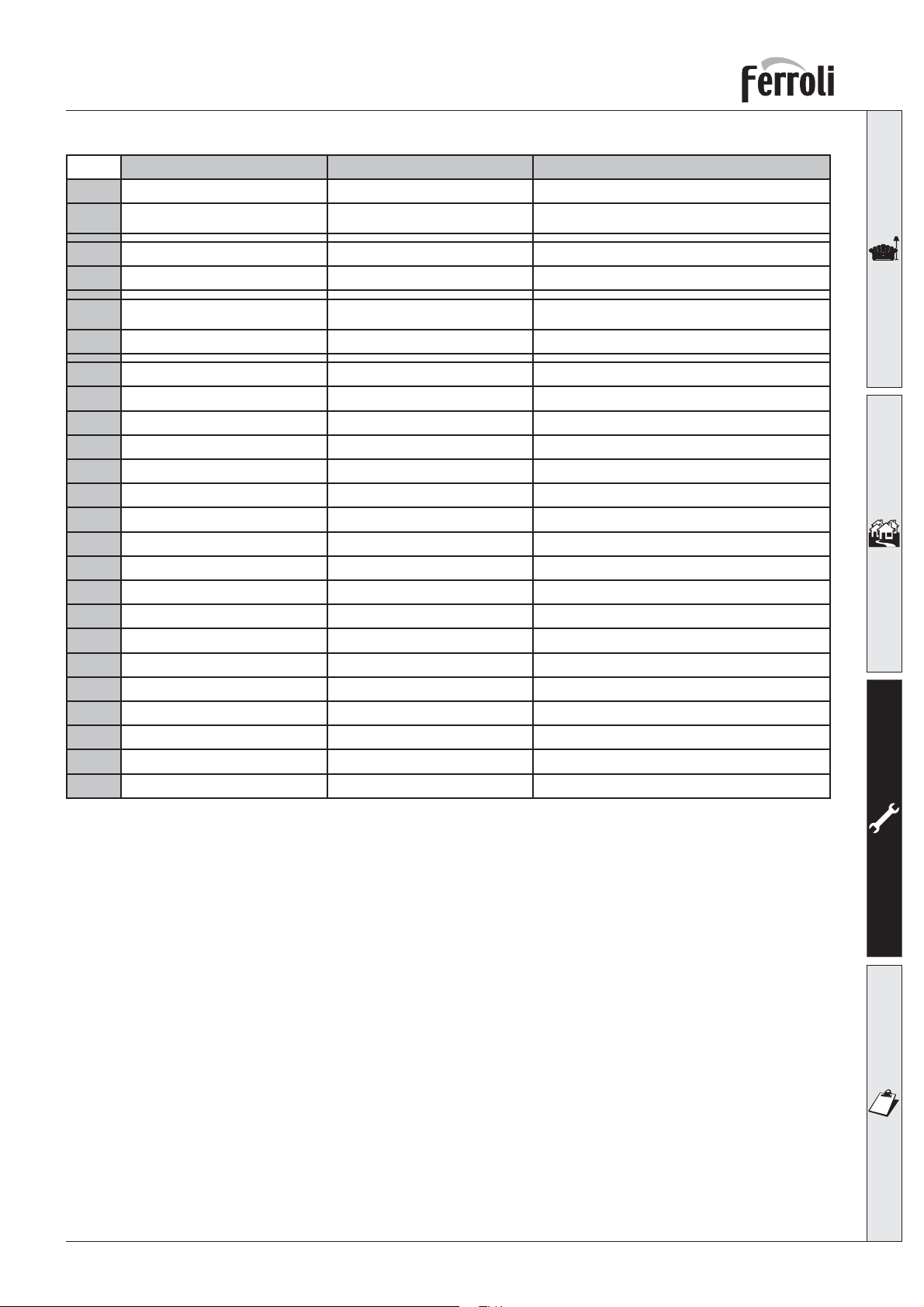
OPTIMAX HE 31 C
Fault Possible cause Cure
Flue sensor fault Sensor damaged or wiring shorted Check the wiring or change the sensor
F13
Flow sensor fault Sensor damaged or short circuited Check the wiring or change the sensor
F14
Sensor damaged or wiring broken Check the wiring or change the
sensor
Sensor damaged or wiring broken Check the wiring or change the sensor
Fan problem Tachometer signal interrupted, fan
F15
Supply voltage under 180V. Electric supply problem Check the electrical system
F34
Irregular mains frequency Electric supply problem Check the electrical system
F35
Incorrect system water pressure Pressure too low Fill the system
F37
External probe fault Sensor damaged or short-circuited Check the wiring or change the sensor
F39
Incorrect system water pressure Pressure too high above 3 - 5 bar Check the fi ll loop not passing
F40
Flow sensor fault Sensor damaged Change the sensor
F42
connection
Fan damaged, debris in fan Check the fan, clean debris
Sensor damaged Check the sensor
Check the wiring and fan
Check the wiring and sensor
Check the safety valve
Check the expansion vessel
N/A for UK market Wiring interrupted Check the wiring
F47
Sensor damaged Replace the sensor
31
Page 32
OPTIMAX HE 31 C
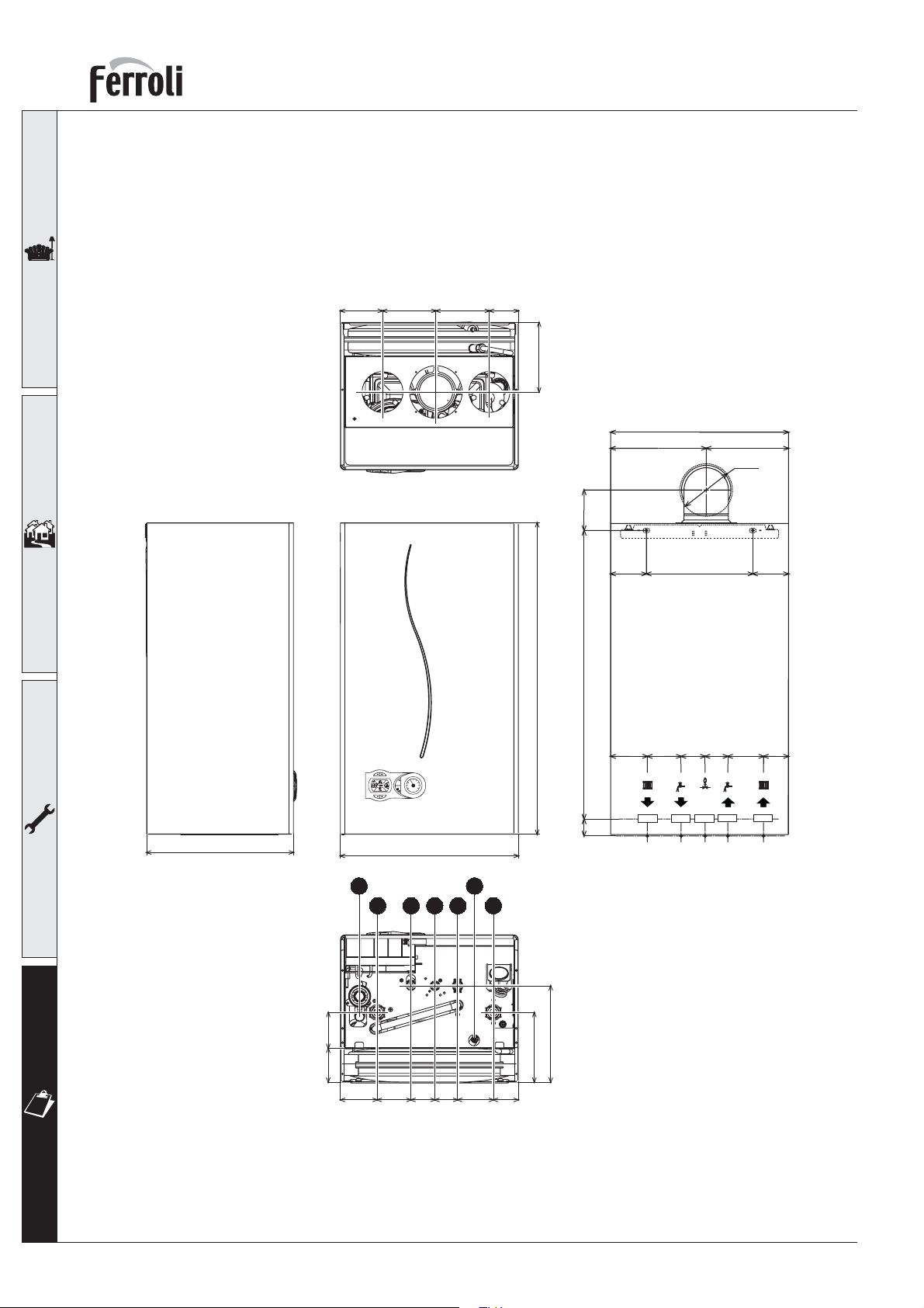
4. TECHNICAL CHARACTERISTICS AND
DATA
4.1 Dimensions and connections
94,7
120
120
65,3
156,2
400
215
91
185
Ø118
330
2
eco
1
3
comfort
reset
0
4
BAR
400
7
1 2 3 465
700
649
38
80
82,5
Ø3/4"
Ø1/2"
80,5
80
56
Ø3/4"
240
Ø1/2"
51
54
Ø1/2"
76
80,5
76,2
82,5
54
75
Key
1 System flow (22 mm with isolation valve fitted)
2 DHW outlet (15 mm)
3 Gas inlet (22 mm with isolation valve fitted)
4 Cold main inlet (15 mm with isolation valve fitted)
32
216,7
156,7
51
80,5
56
fig. 31
5 System return - 22 mm with isolation valve
fitted (c/w filter)
6 Pressure Relief Valve
7 Condense outlet
Page 33
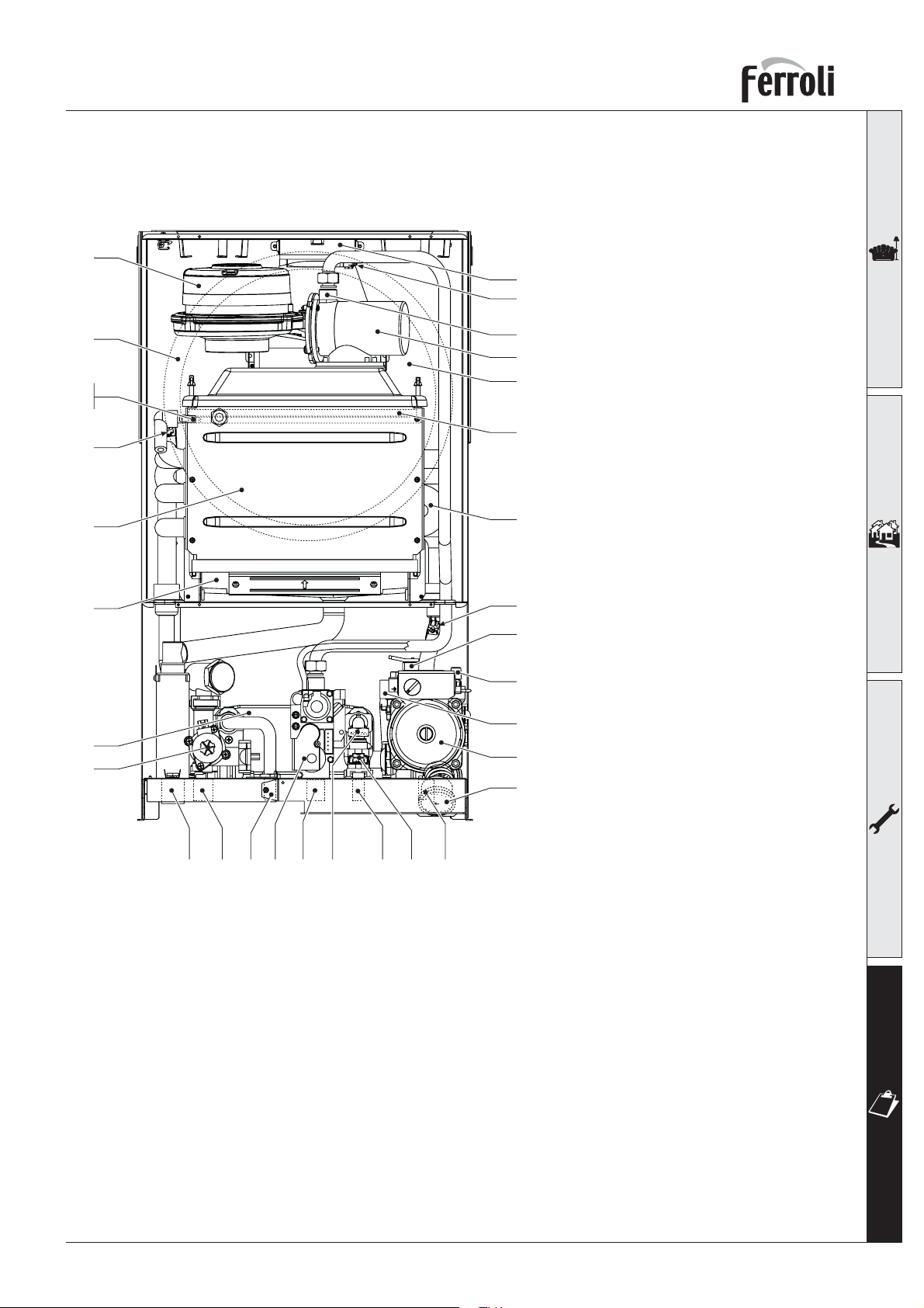
OPTIMAX HE 31 C
4.2 General view and main components
16
56
82
188
278
19
196
194
95
5 Room sealed compartment
7 Gas inlet
8 DHW outlet
29
9 Cold main inlet
191
10 CH flow
11 CH return
21
14 Heating safety valve
16 Premix fan assembly
201
19 Combustion-compartment
5
21 Main injector
22 Main burner
29 Internal flue collar
22
32 Heating pump
36 Automatic air vent
37 Cold water inlet filter
39 Cold water flow limiter
44 Gas valve
161
56 Expansion vessel
82 Ionisation electrode
95 Motorised Diverting valve
136 Flow meter
145 C.h. pressure gauge
154 Condensate outlet pipe
186
161 Heat exchanger
14
186 Return temperature sensor
188 Spark Electrode
191 Flue temperature sensor
36
194 Domestic plate Heat exchanger
196 Condensate collector
201 Fan Venturi
246
246 System pressure sensor
278 Double sensor (Safety + Heating
32
145
flow)
154
10 8 44 7 39 9 1363711
fig. 32
33
Page 34
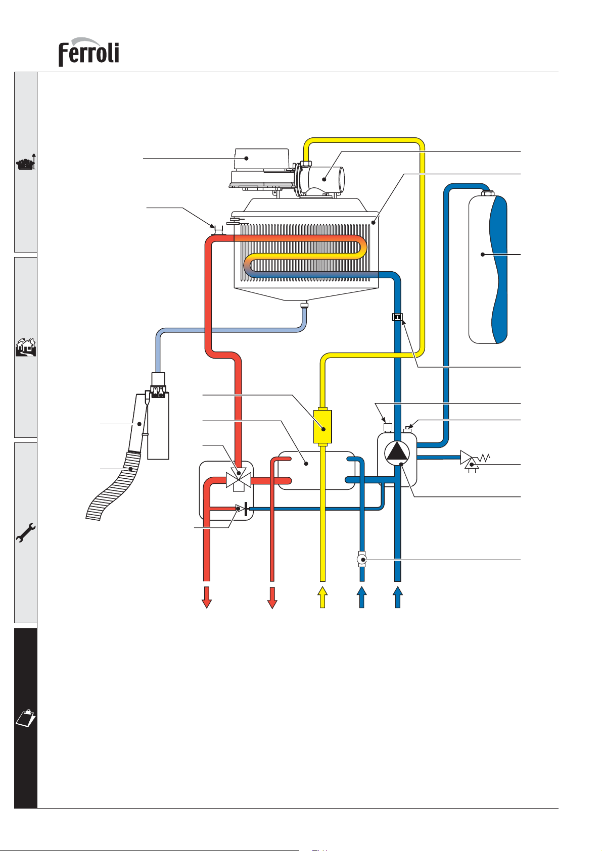
4.3 Hydraulic diagram
OPTIMAX HE 31 C
193
16
278
44
194
201
161
56
186
246
36
95
154
241
Key
7 Gas inlet
8 DHW outlet
9 Cold main inlet
10 CH flow
11 CH return
14 Heating Pressure Relief safety valve
16 Premix fan assembly
32 Heating pump
36 Automatic air vent
44 Gas valve
56 Expansion vessel
9
fig. 33
95 Motorised Diverting valve
136 Flow meter
154 Condensate outlet pipe
161 Heat exchanger
186 Return temperature sensor
193 Siphon
194 Domestic plate Heat exchanger
201 Fan Venturi
241 Automatic by-pass valve
246 System pressure sensor
278 Double sensor (Safety + Heating)
1110 78
14
32
136
34
Page 35
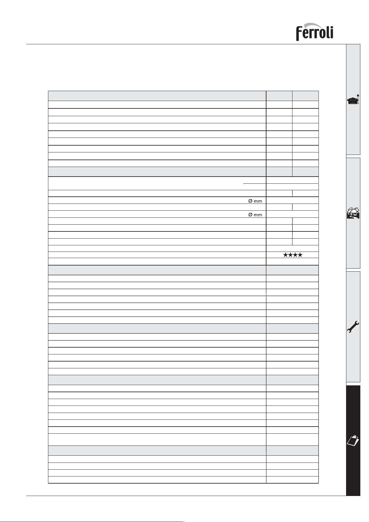
OPTIMAX HE 31 C
4.4 Technical data table
Table 10
Powers
Hi Heating power
Hi DHW power
Useful Heating Power 80° C - 60° C
Useful Heating Power 50° C - 30° C
Useful DHW Power
Natural Gas delivery (G20)
Natural Gas supply pressure (G20)
LPG flow rate (G31)
LPG supply pressure (G31)
Combustion
Seasonal Efficiency (SEDBUK)
Pmax Pmin
kW 25,2 5,3
kW 31,5 5,3
kW 24,6 5,2
kW 26,6 5,7
kW 30,8 5,2
3
m
/h 3,33 0,56
mbar 20 20
kg/h 2,47 0,41
mbar 37 37
Pmax
Pmin
CO2 (G20 - Natural Gas) %
Gas nozzle (G20 - Natural Gas)
CO2 (G31 - Propane) %
Gas nozzle (G31 - Propane)
Flue temperature 80°C - 60°C °C
Flue temperature 50°C - 30°C °C
Flue flow rate kg/h
Quantity of condensate kg/h
pH of condensation water pH
Energy marking (92/42 EEC directive)
NOx emission class
Heating
Heating temperature adjustment range °C
Maximum working temperature in heating °C
Heating circuit PMS safety valve (preset) bar
Minimum working pressure in heating bar
Expansion vessel capacity litres
Expansion vessel pre-filling pressure bar
Total boiler water content litres
Hot water
Hot tap water supply Dt 25° C l/min
Hot tap water supply Dt 30° C l/min
Hot tap water supply Dt 35° C l/min
Tap water temperature adjustment range °C
Maximum working pressure in hot water production bar
Minimum working pressure in hot water production bar
Dimensions, weights connections
Height mm
Width mm
Depth mm
Weight empty kg
Gas system connection (with isolation valve fitted) mm
Heating system connections (with isolation valve fitted) mm
Hot water circuit connections (with isolation valve fitted) mm
Maximum length of separate flues D=80*
(*Measurement given in equivalent linear metres cfr FERROLI calculation system)
m
Electrical power supply
Max electrical power absorbed
Electric power drawn by the circulator (Speed I-II-III) W
Electrical protection rating IP
Power voltage/frequency V/Hz
W
9,0
10
65
46
43
3,3
eq
60-65-70
8,7
5,6
9,5
4,2
60
31
13
1,4
4,1
5
20 - 90
95
3
0.8
7
1
1,5
17,6
14,7
12,6
40 - 55
9
0.25
700
400
330
39
Ø22
Ø22
Ø15
75
135
X5D
230/50
35
Page 36
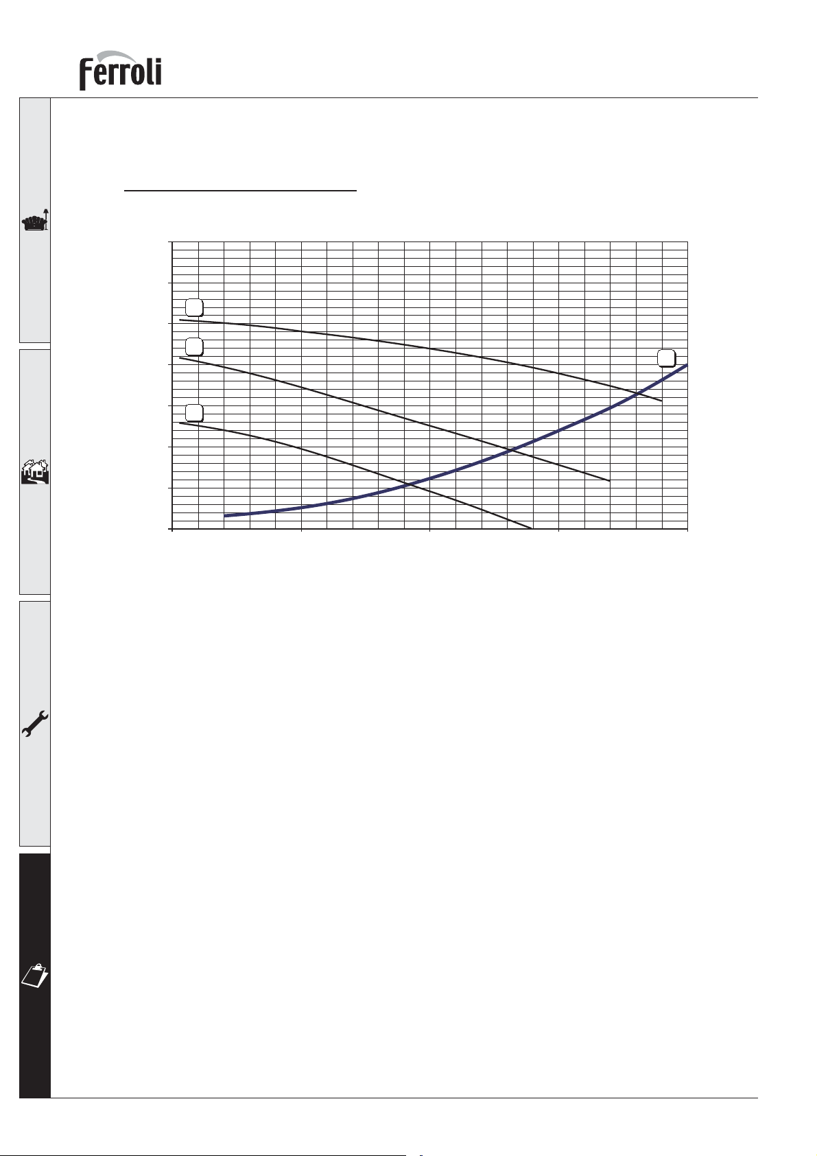
4.5 Diagrams
0
1
2
3
4
5
6
7
0 500 1.000 1.500 2.000
Q [l/h]
H [m H
2
O]
A
3
2
1
Head available for the system
OPTIMAX HE 31 C
fig. 34
Key
1 - 2 - 3 = Pump selector positions
(In order to obtain maximum hot water output the pump must be left in position 3).
A = Boiler losses of head
36
Page 37
OPTIMAX HE 31 C
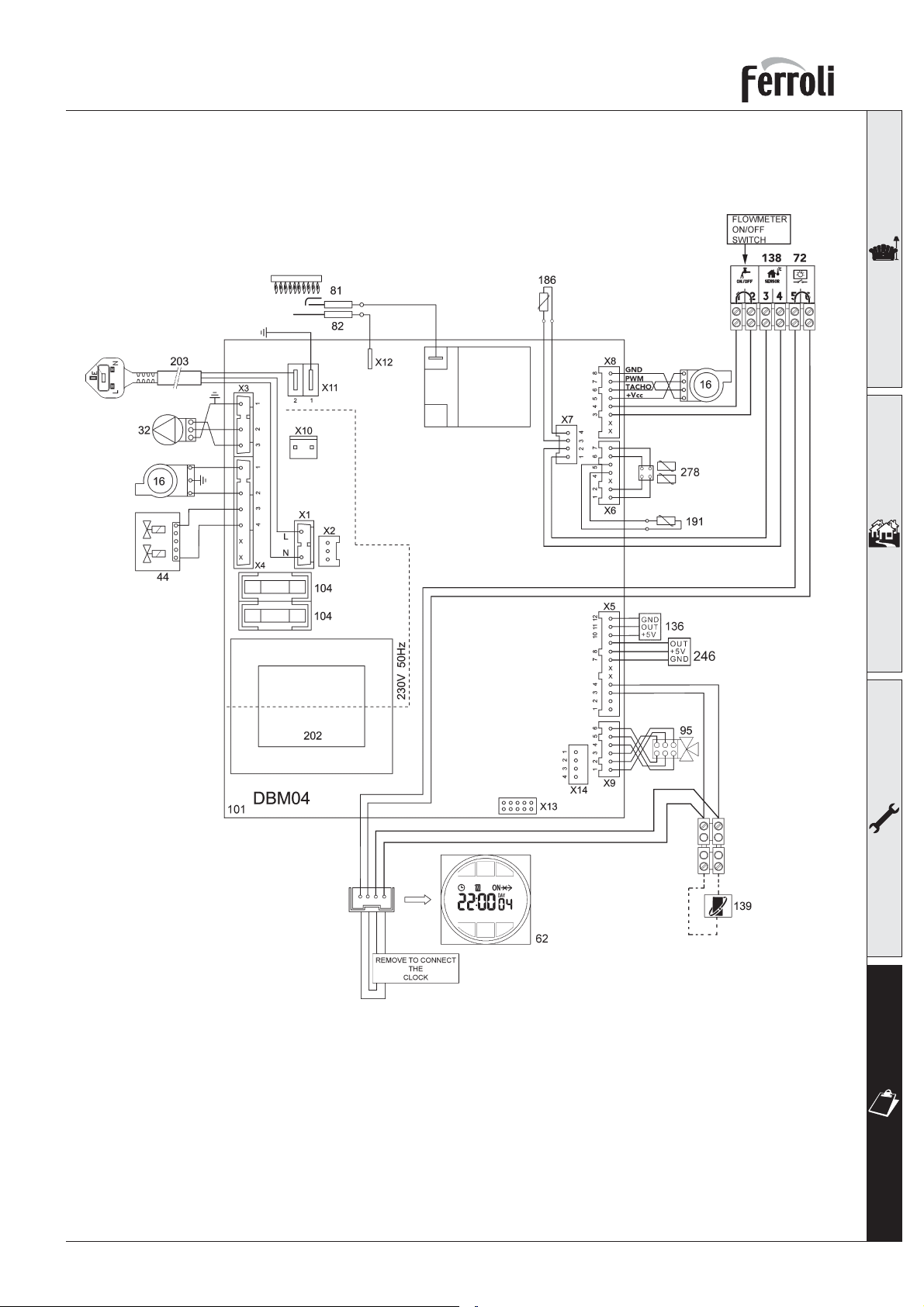
4.6 Wiring diagram
fig. 35
Key
16 Fan
32 Central heating pump
44 Combination gas valve
62 Time clock (optional)
72 Room thermostat
81 Spark Electrode
82 Ionisation electrode
95 Diverting valve
101 Main p.c.b.
104 Fuse
136 Flowmeter
138 Outside temperature sensor
139 Room unit
186 Return temperature sensor
191 Flue temperature sensor
202 Transformer 230V-24V
203 230v A/C switched supply
246 System pressure sensor
278 Double sensor (Safety + Heating)
37
Page 38
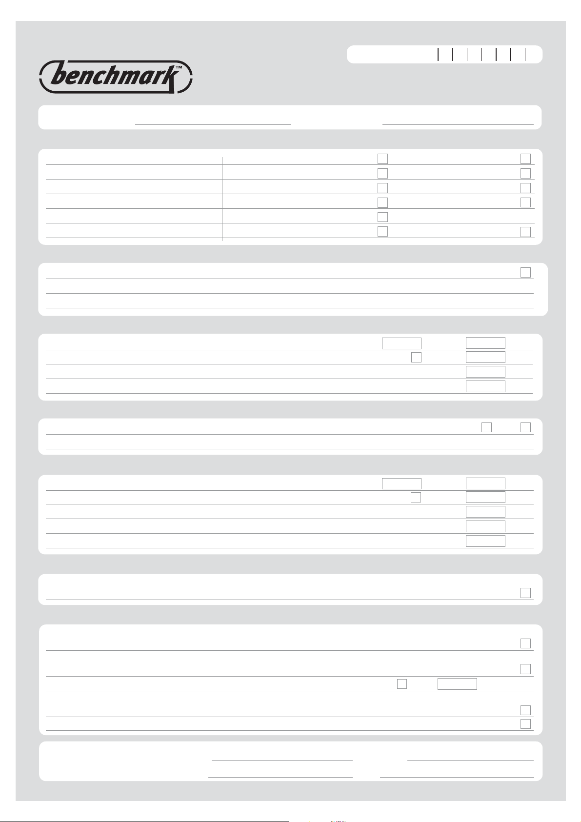
BENCHMARK
BENCHMARK No.
Please add the first 4 digits of the Boiler serial No to complete the BENCHMARK No.
267
COLLECTIVE MARK
GAS BOILER COMMISSIONING CHECKLIST
BOILER SERIAL No. NOTIFICATION No.
CONTROLS To comply with the Building Regulations, each section must have a tick in one or other of the boxes
TIME & TEMPERATURE CONTROL TO HEATING ROOM T/STAT & PROGRAMMER/TIMER PROGRAMMABLE ROOMSTAT
TIME & TEMPERATURE CONTROL TO HOT WATER CYLINDER T/STAT & PROGRAMMER/TIMER
HEATING ZONE VALVES FITTED NOT REQUIRED
HOT WATER ZONE VALVES FITTED NOT REQUIRED
THERMOSTATIC RADIATOR VALVES FITTED
AUTOMATIC BYPASS TO SYSTEM FITTED NOT REQUIRED
COMBI BOILER
FOR ALL BOILERS CONFIRM THE FOLLOWING
THE SYSTEM HAS BEEN FLUSHED IN ACCORDANCE WITH THE BOILER MANUFACTURER’S INSTRUCTIONS?
THE SYSTEM CLEANER USED
THE INHIBITOR USED
FOR THE CENTRAL HEATING MODE, MEASURE & RECORD
GAS RATE ft3/hr
BURNER OPERATING PRESSURE (IF APPLICABLE) mbar
CENTRAL HEATING FLOW TEMPERATURE °C
CENTRAL HEATING RETURN TEMPERATURE °C
m3/hr
N/A
FOR COMBINATION BOILERS ONLY
HAS A WATER SCALE REDUCER BEEN FITTED? YES NO
WHAT TYPE OF SCALE REDUCER HAS BEEN FITTED?
FOR THE DOMESTIC HOT WATER MODE, MEASURE & RECORD
GAS RATE ft3/hr
MAXIMUM BURNER OPERATING PRESSURE (IF APPLICABLE) mbar
COLD WATER INLET TEMPERA
HOT WATER OUTLET TEMPERATURE °C
WATER FLOW RATE
TURE °C
m
N/A
3
/hr
FOR CONDENSING BOILERS ONLY CONFIRM THE FOLLOWING
THE CONDENSATE DRAIN HAS BEEN INSTALLED IN ACCORDANCE WITH
THE MANUFACTURER’S INSTRUCTIONS? YES
FOR ALL INSTALLATIONS CONFIRM THE FOLLOWING
THE HEATING AND HOT WATER SYSTEM COMPLIES
WITH CURRENT BUILDING REGULATIONS
THE APPLIANCE AND ASSOCIATED EQUIPMENT HAS BEEN INSTALLED AND COMMISSIONED
IN ACCORDANCE WITH THE MANUFACTURER’S INSTRUCTIONS
IF REQUIRED BY THE MANUFACTURER, HAVE YOU RECORDED A CO/CO2 RATIO READING? N/A YES CO/CO2 RATIO
THE OPERATION OF THE APPLIANCE AND SYSTEM
CONTROLS HAVE BEEN DEMONSTRATED TO THE CUSTOMER
THE MANUFACTURER’S LITERATURE HAS BEEN LEFT WITH THE CUSTOMER
lts/min
COMMISSIONING ENG’S NAME PRINT CORGI ID No.
SIGN DATE
Page 39
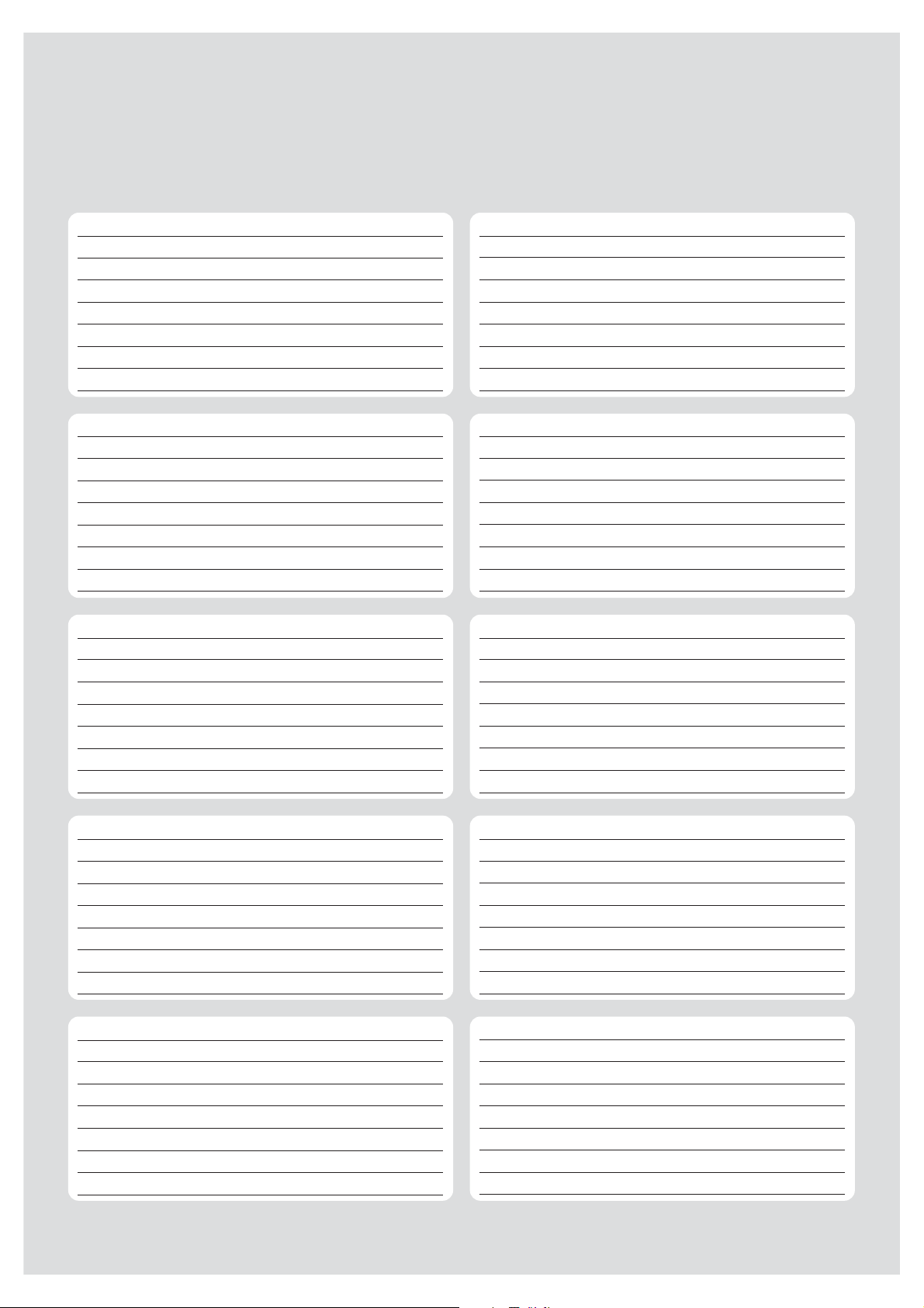
SERVICE INTERVAL RECORD
It is recommended that your heating system is serviced regularly
and that you complete the appropriate Service Interval Record Below.
Service Provider. Before completing the appropriate Service Interval Record below, please ensure you have carried out the service
as described in the boiler manufacturer’s instructions. Always use the manufacturer’s specified spare part when replacing all controls
SERVICE 1
ENGINEER NAME
COMPANY NAME
TEL No.
CORGI ID CARD SERIAL No.
COMMENTS
SIGNATURE
SERVICE 3
ENGINEER NAME
COMPANY NAME
TEL No.
CORGI ID CARD SERIAL No.
COMMENTS
SIGNATURE
SERVICE 5
ENGINEER NAME
COMPANY NAME
TEL No.
CORGI ID CARD SERIAL No.
COMMENTS
DATE
DATE
DATE
SERVICE 2
ENGINEER NAME
COMPANY NAME
TEL No.
CORGI ID CARD SERIAL No.
COMMENTS
SIGNATURE
SERVICE 4
ENGINEER NAME
COMPANY NAME
TEL No.
CORGI ID CARD SERIAL No.
COMMENTS
SIGNATURE
SERVICE 6
ENGINEER NAME
COMPANY NAME
TEL No.
CORGI ID CARD SERIAL No.
COMMENTS
DATE
DATE
DATE
SIGNATURE
SERVICE 7
ENGINEER NAME
COMPANY NAME
TEL No.
CORGI ID CARD SERIAL No.
COMMENTS
SIGNATURE
SERVICE 9
ENGINEER NAME
ANY NAME
COMP
No.
TEL
CORGI ID CARD SERIAL No.
COMMENTS
SIGNATURE
DATE
TE
DA
SIGNATURE
SERVICE 8
ENGINEER NAME
COMPANY NAME
TEL No.
CORGI ID CARD SERIAL No.
COMMENTS
TURE
SIGNA
SERVICE 10
ENGINEER NAME
COMPANY NAME
TEL No.
CORGI ID CARD SERIAL No.
COMMENTS
SIGNATURE
DATE
DATE
FERROLI TECHNICAL HELPLINE - 08707 282 885
Page 40

Should you require any assistance during the installation
Should you require a service engineer to visit
Phone numbers:
Installer
Service Engineer
call our Technical Service Helpline on
08707 282 885 option 1
call our service centre on
08707 282 885 option 2
(For U.K. and Northern Ireland)
For EIRE only call HEATOVENT on
014508166
BECAUSE OF OUR CONSTANT ENDEAVOUR FOR IMPROVEMENT DETAILS
MAY VARY SLIGHTLY FROM THOSE QUOTED IN THESE INSTRUCTIONS.
ALL SPECIFICATIONS SUBJECT TO CHANGE
Please note - to avoid incurring unnecessary expense, in the event of a boiler shut down, check
this is not caused by lack of electricity supply, gas supply or low water pressure before calling our
Customer Service Helpline.
Lichfield Road, Branston Industrial Estate, Burton Upon Trent, Staffordshire DE14 3HD
Tel. 08707 282 885 - Fax 08707 282 886
EIRE only:
HEATOVENT Greenhills Industrial Estate,
Greenhills Road, Walkinstown, Dublin 12, IRELAND
Tel 014508166 - Fax 014508501
 Loading...