

Page 1
201
WALL MOUNTED,
GAS COMBINATION BOILER
INSTALLATION
INSTRUCTIONS
W.R.C. No. 9207075
LEAVE THESE INSTRUCTIONS
ADJACENT TO THE GAS METER
Appr. Nr. B94.05T CE 0063AQ2150
Phone numbers:
Installer
Service Engineer
Serial No.
FERROLI HELPLINE
FOR SERVICE INFORMATION OR
HELP TELEPHONE: 08707 282 885
ALWAYS QUOTE YOUR SERIAL NUMBER
FOR IMMEDIATE ASSISTANCE
ALL SPECIFICATIONS SUBJECT TO CHANGE
Lichfield Road, Branston Industrial Estate, Burton Upon Trent, Staffordshire DE14 3HD
Tel. 08707 282 885 - Fax 08707 282 886
Page 2

page INDEX
3 General Description
3 Related Documents
4 Technical Data
5 Appliance Dimensions
6 Boiler Flow Diagram
8 Installation Details
8 1. Location of Boiler
8 2. Air Supply
8 3. Flue System
10 4. Gas Supply
11 5. Water System
12 Central Heating Pump
13 Sizing of expansion vessel
15 Installation of Boiler
15 1. Unpacking
15 2. Mounting the Boiler Jig
on the Wall
16 3. Connecting the Boiler
17 4. Electrical Installation
18 Time clock
19 Removal of clock
20 5. Commissioning & Testing
20 5.1Filling the Central Heating System
20 5.2Filling the Domestic Hot Water System
20 5.3Electricity Supply
20 5.4The Gas Installation
21 5.5To Light the Boiler
22 5.6To Range Rate the Boiler C.H.
23 Gas pressure adjustment with Honeywell
VR 4600 N 4002 valve
24 5.7D.H.W. Burner Pressure
24 6. System operation
24 7. Handing Over to the User
25 General Wiring Diagram
26 Electrical Functional Flow Wiring Diagram
27 Domestic Hot Water
Performance + Modureg
28 Spare parts list
201
For "Fast" Fault Finding see separate instructions inside the electrical control box or page 59
2
Page 3

201
General Description
The Ferroli 201 is a wall mounted combination boiler for Central Heating (C.H.) and domestic Hot
Water (D.H.W.).
The boiler is of light weight construction and the heat exchanger provides Central Heating and Domestic
Hot Water from an integrally designed unit. The boiler contains its own expansion vessel for sealed systems.
The wall mounting jig contains all the isolating cocks for the water and gas supplies which can be fitted to
the wall and provided with all the necessary gas and water connections prior to the boiler being attached.
The Central Heating and the Domestic Hot Water temperature is controlled by the Honeywell Modureg valve
in conjunction with the P.C.B. There is a limit thermostat on the central heating circuit which operates at 88°C.
There is also an overheat cut-off thermostat which will shut the boiler down completely and this thermostat
operates at 100°C. The boiler is fited with its own Central Heating pump. The pump is switched ON/OFF
by the time clock and/or a 24 Volt room thermostat. The pump circuit also has a 6 minute over-run time. There
is a Domestic Hot Water flow switch fitted and when there is a demand for Domestic Hot Water (flow
of more than 0.5 gallon/minute, 2.5 litre/minute) the Central Heating pump is switched off making available
the maximum output of the gas burner for Domestic Hot Water. On the P.C.B. the maximum output for Central
Heating can be set. This does not influence the maximum output for domestic hot water.
At the factory the central heating output is pre-set to maximum. The appliance is not suitable for external
installation.
Related Documents
This appliance must be installed strictly in accordance with these instructions:
The Gas Safety Regulations (Installations & Use) 1994.
The Local Building Regulations.
The Building Regulations.
The Buildings Standards (Scotland - Consolidated) Regulations.
British Standards Codes of Practice:
B.S. 7593 1993 TREATMENT OF WATER IN DOMESTIC HOT WATER CENTRAL HEATING SYSTEMS
B.S. 5546 1990 INSTALLATION OF HOT WATER SUPPLIES FOR DOMESTIC PURPOSES
B.S. 5440 PART 1 FLUES
B.S. 5440 PART 2 AIR SUPPLY
B.S. 5449 1990 FORCED CIRCULATION HOT WATER SYSTEMS
B.S. 6798 1987 INSTALLATION OF GAS FIRED HOT WATER BOILERS
B.S. 6891 1989 GAS INSTALLATIONS
B.S. 7671 1992 IEE WIRING REGULATIONS
B.S. 4841 1990 SPECIFICATION FOR EXPANSION VESSALS
Model Water Bye Laws.
3
Page 4

201
Technical Data G20 G31
Nominal Heat Input D.H.W. & C.H. (gross) 28.6 kW 28.0 kW
Minimum Heat Input D.H.W. & C.H. (gross) 12.8 kW 12.5 kW
Nominal Heat Input D.H.W. & C.H. (net) 25.8 kW 25.8 kW
Minimum Heat Input D.H.W. & C.H. (net) 11.5 kW 11.5 kW
Nominal Heat Output D.H.W. & C.H. 23.3 kW 23.3 kW
Minimum Heat Output D.H.W. & C.H. 9.7 kW 9.7 kW
(See section 8.6 for range setting of Central Heating - D.H.W. is preset and not adjustable)
Maximum Gas Rate 2.72 m
Maximum Burner Pressure 14.5 mbar 36.0 mbar
Minimum Burner Pressure 2.7 mbar 7.9 mbar
Injector Marking (Main Burners) 210
Injector Size (4 off) 2.10 mm
Pilot Injector Marking 38/33A
Dimensions (overall):
Height 1020 mm
Width 480 mm
Depth 360 mm
Weight (nett) 51 kg
Weight (gross) 53 kg
Electricity supply: 230 V ~ 50 Hz
External fuse 3 A
Internal fuses on P.C.B. F2A to BS4265 - (2 Amp. Fast)
Electrical Input 150 W
Central Heating:
Max. Flow Temperature 85°C
Temperature Rise Across Boiler 20°C
Domestic Hot Water Flow:
30°C Rise 11.1 litres/min.
32°C Rise 10.4 litres/min.
35°C Rise 9.5 litres/min.
40°C Rise 8.3 litres/min.
Minimum Domestic Hot Water Flow 2.5 litres/min.
Maximum Domestic Cold Water Inlet pressure 10 bar
Minimum Heating Circuit Pressure 0.8 bar
Maximum Heating Circuit Pressure 3.0 bar
Boiler Water Capacity: Heating 2.0 litres
Domestic Hot Water 0.5 litres
Connections:
Gas 22 mm
Domestic Hot Water Outlet 15 mm
Domestic Cold Water Inlet 15 mm
Pressure Relief Valve Drain 15 mm
Central Heating Flow 22 mm
Central Heating Return 22 mm
Minimum Installation Clearances:
Sides -Left hand 5 mm*
Right hand 5 mm*
Front 50 mm**
Minimum Clearance below 200 mm
Minimum Clearance above 100 mm
3
/h 2.66 m3/h
Notes:
* If using a side outlet flue then the
minimum clearance on the flue outlet
side of the appliance must be increased
to 75 mm (3 in).
** Access to the front of the boiler must be
available for maintenance (min. 600 mm)
4
Page 5
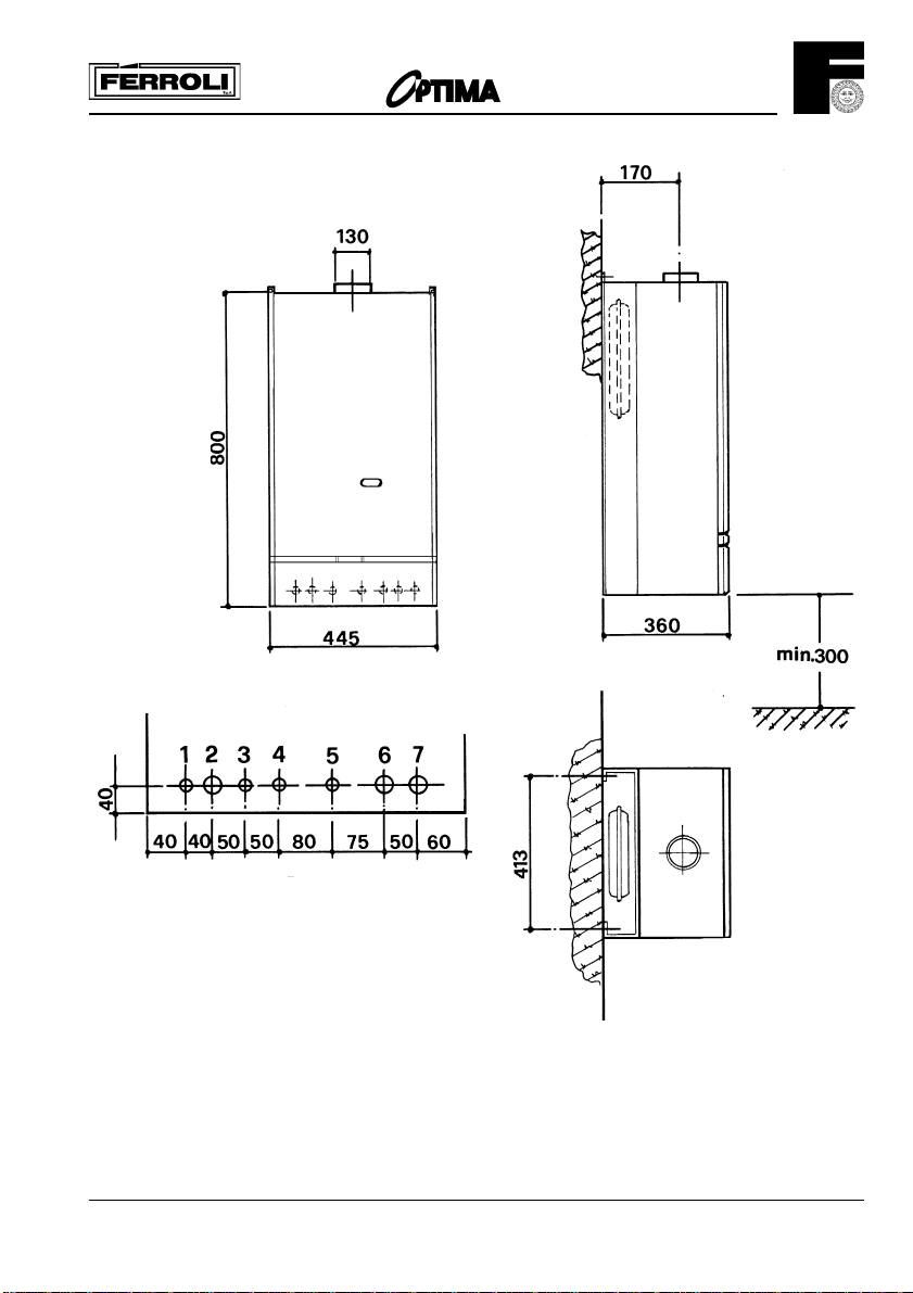
Appliance Dimensions
201
Key
1. Electricity cable entry
2. Gas supply
3. Domestic Hot Water outlet
4. Domestic Cold Water inlet
5. Central Heating Pressure relief valve
6. Central Heating Flow outlet
7. Central Heating Return inlet
Fig. 1
5
Page 6
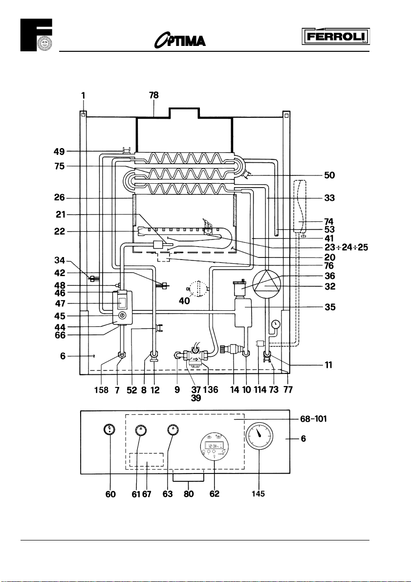
Boiler Flow Diagram
201
Fig. 2
6
Page 7

Key
1. Fixing point
6. Control panel
7. Gas inlet
8. Domestic hot water outlet
9. Cold water inlet
10. Central heating flow outlet
11. Central heating return inlet
12. D.H.W. draining point
14. Central heating safety valve
20. Burner assembly
21. Main injector (4)
22. Burner (4)
23. Thermocouple
24. Spark electrode
25. Pilot
26. Combustion chamber insulation
32. Central heating pump
33. C.H. waterway of the heat exchanger
34. C.H. flow temperature sensor
35. Air separator
36. Automatic air vent
37. Cold water inlet filter
39. Cold water flow limiter
40. Domestic hot water expansion vessel (optional)
41. D.H.W. waterway of the heat exchanger
201
42. D.H.W. temperature sensor
44. Combination gas valve
45. Knob gas valve
46. Operator gas valve
47. Modulating regulator (Modureg) gas valve
48. Burner pressure test point
49. Overheat cut-off thermostat
50. Central heating limit thermostat
52. D.H.W. limit thermostat
53. Heat exchanger venting point
60. Extended control knob to gas valve
61. C.H. selector switch
62. Time clock
63. C.H. boiler thermostat
66. Microswitch combination gas valve
67. Ignition transformer
68. Control box with P.C.B.
72. Room thermostat (not fitted)
73. Frost thermostat (not fitted)
74. Expansion vessel
76. Air filter
80. 240 V + 24 V roomstat terminal blocks
101. P.C.B. (printed circuit board)
114. Water pressure switch
136. Flowmeter
145. C.H. pressure gauges
158. Gas inlet pressure test point
Gas Safety (Installation & Use) Regulations: 1994
In the interest of safety, it is the law that all gas appliances are installed by a competent person in accordance
with the above Regulations, Building Regulations/Building Standards Scotland, Codes of Practice, current
I.E.E. Regulations and the byelaws of the Local Water Undertaking. Failure to comply with the Regulations
may lead to prosecution; it is in your interest and that of safety to ensure that the law is complied with.
Important - If the boiler is to be fitted in a timber framed buiding it should be fitted in accordance
with the British Gas publication; Guide for Gas Installation in Timber Frame Housing: Reference DM2.
If in doubt advice must be sought from the Local Gas Region of British Gas Plc.
7
Page 8

201
Installation Details
Location of Boiler
The installation of the
provide an adequate fixing for the boiler mounting bracket assembly. A satisfactory flue with a minimum of
600 mm (2 ft.) rising vertically above the draught diverter must also be provided, terminating in a British Gas
Approved cowl.
The location must also provide adequate room for servicing.
The location must also be provided with an adequate air supply for combustion purposes. The boiler must
not be installed in a room containing a bath or shower, or in a bedroom or bed-sitting room. In installations
of an unusual location, special procedures are necessary and BS 6798 gives detailed guidance on this
aspect. The location should be as centralised as possible with the water piping system and in an area not
subjected to frost conditions.
Flue system
Detailed recommendations for flue are given in BS 5440 Part. 1. The following notes are intended for general
guidance. The cross sectional area of flue serving the boiler must not be less than the area of the flue outlet
of the appliance.
The flue should terminate in accordance with BS 5440 Part 1. The boiler has a flue spigot designed for
aluminium or stainless steel flue pipe. If double walled flue pipe is used, it should be of a type accepted by
British Gas. Always use a split flue clip or flanged joint above the flue diverter to allow the removal of the boiler.
A vertically rising flue above the diverter for a minimum length of 600 mm (2 ft.) is required before any bend
is fitted, which should not be a 90° pattern. The flue pipe must be adequately supported and not be in contact
with any inflammable material.
If any existing chimney is to be used, it should be lined with a stainless steel flexible liner or any other liner
acceptable to British Gas. (Chimneys lined with salt glazed earthenware pipes are acceptable if the pipes
conform to BS 65.). The number of metal flue liner joints should be kept to the minimum for connecting the
boiler to an existing flue, the flue must be clean of any soot or loose material. Dampers must be removed.
The flue should be, as far as is practical, vertically rising with the avoidance of horizontal runs. The metal flue
pipe listed above should form the initial connection from the boiler to the existing chimney (and liner). Refer
to page 12 if an extraction fan is fitted in the area.
201 must be on a suitable non-combustible load bearing wall which will
Air supply
Detailed recommendations are given in BS 5440 Part. 2. The following notes are intended to give guidance.
Room or internal air space supply:
The
or to an adjacent room which must itself have a permanent air vent of the same size, direct to outside air. The
minimum size of this air vent must be: 94 cm2 free a (14 in2). A proprietry air vent may be marked with its
effective free area, if not, this infor-mation can usually be supplied by the maker. The vent should be designed
to diffuse the air in windy conditions and should be sited to reduce room draughts, i.e. at top level. The
aperture in the vent should not pass preferably, a 10 mm (318 in.) ball but allow the entry of a 5 mm (3116
in.) ball. (Additional gauzes or screens should not be used).
Existing air vents should be taken into account when assessing air vent requirements. An air vent in an
internal wall should not communicate with a bedroom, toilet, bathroom or kitchen and should not be more than
450 mm (18 in.) above floor level in order to reduce the spread of smoke in the event of a fire. An air vent
direct to outside air must not be loca-ted less than 600 mm (2 ft.) away from any part of an open flued terminal.
8
201 requires a permanent air vent for combustion air either from the room direct to outside air
Page 9
201
Cupboard or compartment air supply:
If the appliance is to be installed in a compartment or cupboard if existing, it should be of sufficient size. This
compart-ment or cupboard must have permanent air vents for combustion air, flue dilution and cooling
purpose!s, the vents being positioned at high and low level. The following minimum size of air vents (free area)
are required:
Position of Air vent Air from room or internal space Air direct from outside
High 252 cm
Low 504 cm
2
(38 in2) 126 cm2 (19 in2)
2
(76 in2) 252 cm2 (38 in2)
NOTE
Both air vents must communicate with the same room or must be on the same outside wall to outside air.
Where cupboard compartment air vents are open to a room, the room itself must have a permanent air vent(s)
as previously specified.
IMPORTANT
If the boiler is installed in hair dressers premises, ventilation must not be from areas in which aerosol hair
spray is being used. Any spray or materials emitting volatile vapours can be a source of ignition from the
perrnanent pilot of the boiler. Propellants of aerosol srays and fumes of volatile compounds in addition to
being highly flammable in many cases, will also change to corrosive hydrochloric acid when exposed to the
products of combustion of the boiler. The results may be hazardous, causing service problems and produce
failure.
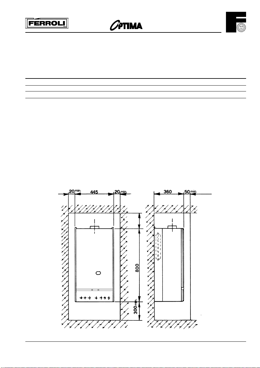
Minimum clearances
200
Fig. 3
9
Page 10
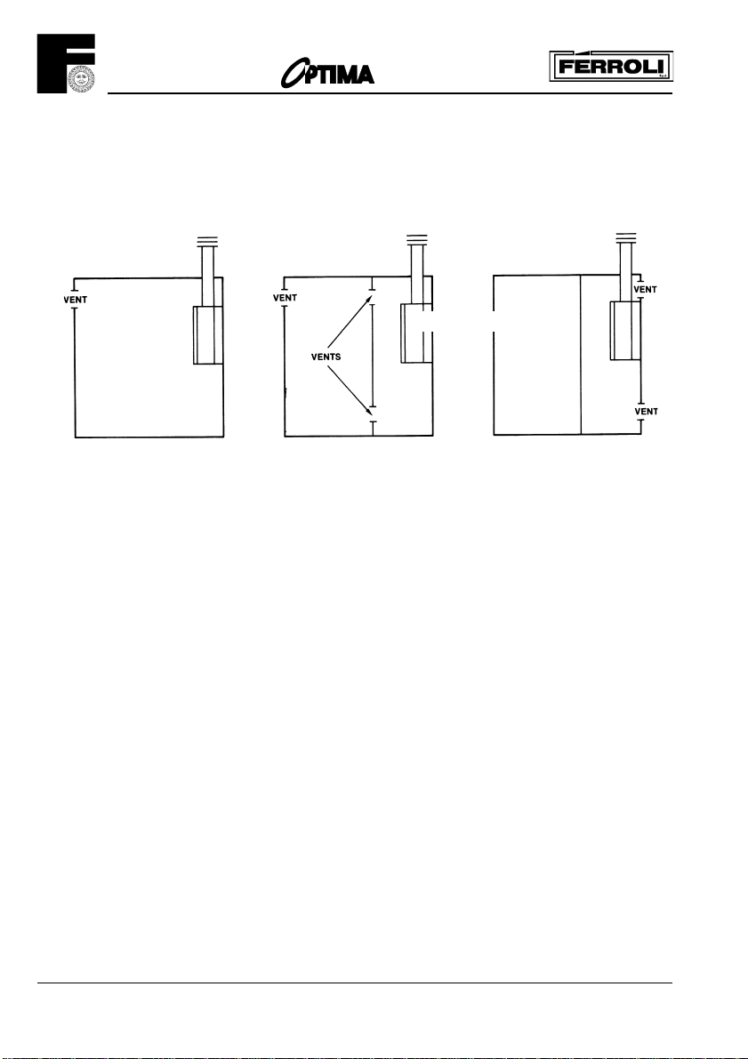
Cupboard or compartment installation
201
1. Boiler in a room
2. Boiler in a cupboard
Vented to a room
3. Boiler in a cupboard
Vented to outside
Fig. 4
Effect of an extract fan
If there is type of extract fan fitted in the premises, there is the possibility with open flued appliances, that if inadequate
fresh air vents are not provided, spillage of products from the flue diverter could take place, when the fan is in operation.
Where such installations are found, a test for spillage must be carried out as described in Part. 1 of BS 5440, and the
necessary action taken.
Gas Supply
If necessary the local Gas Region should be consulted, at the installation planning stage, in order to establish the
availability of an adequate supply of gas.
An existing service pipe must not be used without prior consultation with the Local Gas Region.
A gas meter can only be connected by the Local Gas Region, or by a Local Gas Region's Contractor.
Installation pipes should be fitted in accordance with BS6891-1988.
Pipework from the meter to the combination boiler must be of an adequate size.
The boiler requires 2.72 m
WE REQUIRE 22 mm PIPE FROM THE METER TO THE BOILER.
The complete installation must be tested for gas soundness and purged as described in BS6891-1988. All pipework must be
adequately supported. An isolating gas valve is provided and should be fitted on manifold assembly.
3
/h of natural gas.
Water System
10
Page 11
201
Central Heating
It must be a sealed system. Detailed recommendations are given in BS6798, BS5449, BS6700 and CP342 Part. 2. Pipework
not forming part of the useful heating surface should be insulated to prevent any heat losses or possible freezing (i.e. in roof
spaces or ventilated underfloor spaces). Drain taps should be positioned at the lowest point of the system in accessible
locations to permit the whole system to be drained down. The drain taps should be in accordance with BS2879. Copper tubing
to BS2871, Part. 1 is recommended for water carrying pipework. Pipework in horizontal runs should have a gradient where
possible to facilitate the removal of air. It should be ensured that the boiler heat exchanger is not a natural point for collecting
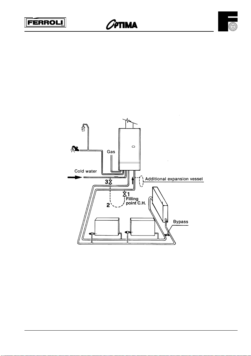
air. A typical heating system with domestic hot water circuit is illustrated in fig. 5.
Important - A bypass must be fitted as far as possible from the boiler if thermostatic radiator valves are fitted throughout.
Key
1. Filling point C.H.
2. Temporary connection
3. Cold water supply
Make up Water
Fig. 6
11
Page 12
201
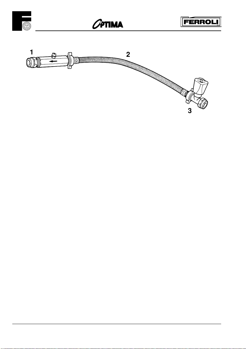
1. Filling point C.H.
2. Temporary connection
3. Cold water supply
Provision must be made for replacing water lost from sealed system. Reference should be made to BS6798, for methods of
filling and making up sealed systems. There must be no direct connection between the boiler's central heating system and the
mains water supply. The use of mains water to charge and pressurise the system directly, is conditional upon the Local Water
Byelaw. Again any such connection must be disconnected after use.
Domestic Hot Water
Always fit a water softener or descaler in «hard water areas». A 15 mm copper connection point on the boiler jig bracket for
attaching to the main supply is provided. The maximum domestic water pressure for the inlet supply is 10 bar (145 P.S.I.). If the
cold mains supply exceeds 5 bar, a water governor or pressure reducing valve must be fitted by the installer into the mains supply
in an inconspicuous but accessible position.
Such a valve must be approved by the Water Research Council.
Attention - Is drawn to the Model Water Byelaws.
Fittings manufactured from duplex (alpha-beta) brass are not acceptable for underground use and certain water
undertakers will not accept their use above ground.
Fig. 6
Key
Built-in Central Heating Water Circulating Pump
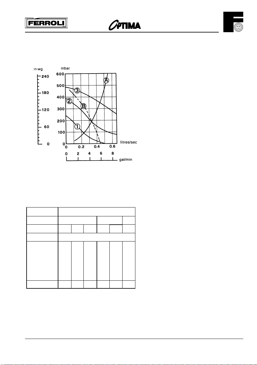
The pump head available for circulating the water is given in fig. 7.
N.B. - The pump is factory set at position 3. The pump is a Grundfos type 15-50 UPS series.
Grunfos Pump performance graph
1 2 3 Speed settings
A Boiler pressure drop
B Max. available pump head C.H.
Note - Minimum flow through boiler heat exchanger at any time should not fall below 6 litres per minute.
If required an additional expansion vessel may be fitted to the central heating return inlet.
If the total volume of water in the system exceeds 40 litres an additional expansion vessel must be fitted to
the central heating return inlet.
Pump performance curve Grundfos UPS 15-50
12
Page 13
Installation of boiler
SIZING OF ADDITIONAL EXPANSION VESSELS:
Deduct from the value given in the table the 7 litre vessel supplied.
SAFETY VALVE
SETTING (bar)
VESSEL CHARGE
PRESSURE (bar)
INITIAL SYSTEM
PRESSURE (bar)
TOTAL WATER
CONTENT of SYSTEM
LITRES
25 3.5 6.5 13.7 4.7 10.3 8.3
50 7.0 12.9 27.5 9.5 20.6 16.5
75 10.5 19.4 41.3 14.2 30.9 24.8
100 14.0 25.9 55.1 19.0 41.2 33.1
125 17.5 32.4 68.9 23.7 51.5 41.3
150 21.0 38.8 82.6 28.5 61.8 49.6
175 24.5 45.3 96.4 33.2 72.1 57.9
200 28.0 51.8 110.2 38.0 82.4 66.2
For syst. volumes other than
those given above, mult. the syst.
volume by the factor across
0.5 1.0 1.5
1.0 1.5 2.0 1.5 2.0 2.0
EXPANSION VESSEL VOLUME (litres)
0.140 0.259 0.551 0.190 0.412 0.33
3.0
201
1 2 3 Speed settings
A Boiler pressure drop
B Max. available pump head C.H.
Fig. 7
Note
1. Fill C.H. installation to min. 1.5 bar.
2. Select by preference the expansion vessel for increased
system pressure of 2.0 bar
3. Expansion vessel must be fitted to Central Heating Return
Inlet
4. The standard 7 litres expansion vessel is charged to 1 bar
Fig. 8
13
Page 14
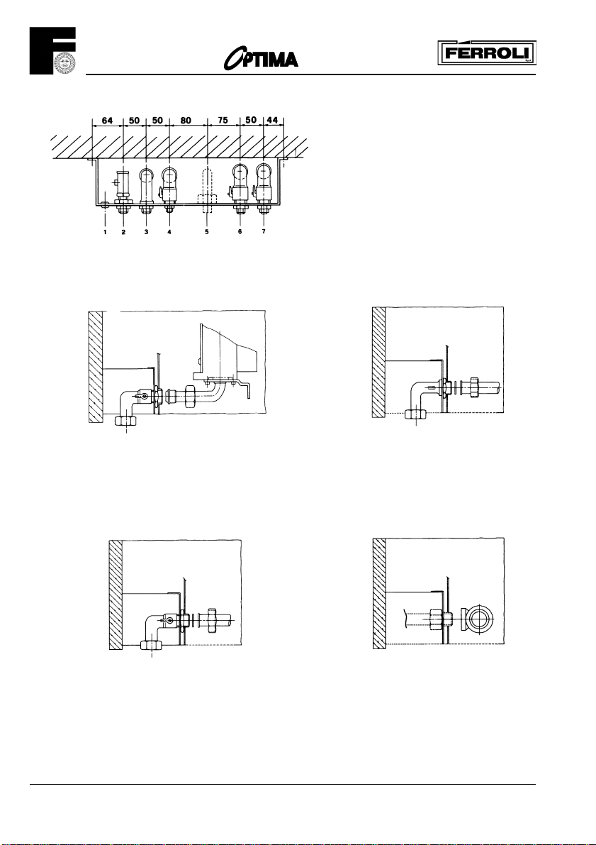
201
1 = Electrical cable entry
2 = Gas supply
3 = Domestic Hot Water outlet
4 = Domestic Cold Water Inlet
5 = Outlet Central Heating safety valve
6 = Central Heating flow outlet
7 = Central Heating return inlet
3 Domestic hot Water outlet 15 mm2 Gas
22 mm gas supply must be within 3 m of boiler. Final connetion only in 15 mm.
4 Domestic cold Water inlet 15 mm
6 Central Heating flow outlet 22 mm
7 Central Heating return inlet 22 mm
Fig. 9
5 Outlet central heating safety valve 15 mm
Important Note - Always use two spanners to prevent twisting of soft copper pipework.
Note - The central heating safety valve (5) should be piped 15 mm to discharge safely outside the property.
14
Page 15

201
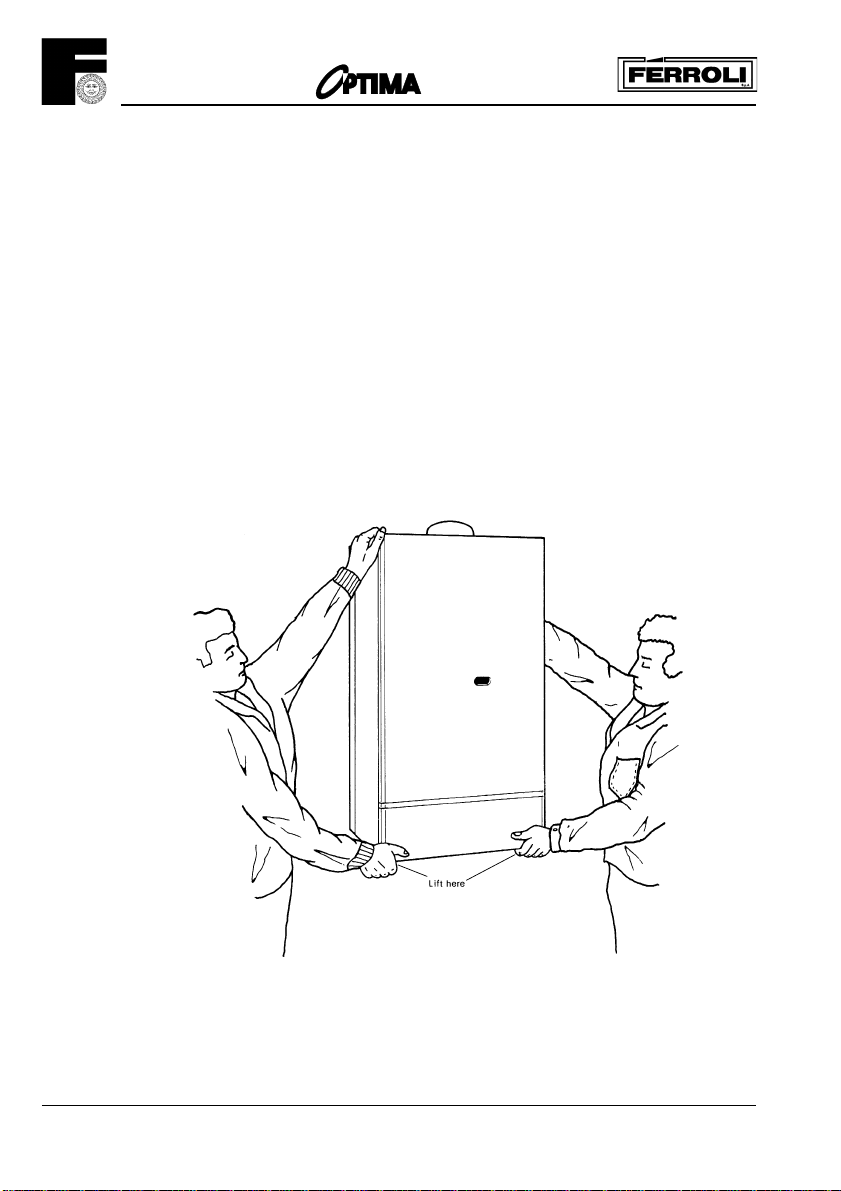
Note - To mount the boiler on the wall, a two person lift will be needed.
1.0 UNPACKING
The appliance is delivered in two cartons.
1.1 The large carton contains the boiler, and the Installation/Servicing and Users Instruction.
1.2 One carton contains the mounting jig assembly, complete with isolating valves, the assembly fixing
screws and wall plugs (x4), the boiler mounting nuts and washers (x2) and drilling template.
When the cartons are unpacked examine for any signs of damage in transit.
All protective plastic should be left in place until installation is complete.
2.0 FIXING THE MOUNTING JIG ON THE WALL
2.1 Select the boiler location carefully ensuring that alla requirements given in previous text are satisfied.
Fig. 3 will also give guidance to fixing dimensions.
2.2 Locate template on wall, mark the positions of the four jig bracket fixing holes.
2.3 Using a 10 mm drill, drill 70 mm deep holes to accept the wall plugs, and insert wall plugs.
2.4 Fit the mounting jig assembly using the four fixing screws provided
(Ensure that all the service cocks are in the OFF position).
2.5 With the exception of the connection to the pressure relief valve, make all the water and gas
connections to the jig bracket valves. Fully tighten (fig. 9). Before the gas inlet to the boiler there must
be at least 100 mm of straight before any bends, to allow access to the union nut.
Important Note - Always use two spanners to prevent twisting of soft copper pipework on the boiler.
Flush out the water system.
Note - The maximum inlet cold water pressure must not exceed 10 bar (145 P.S.I.) and a water
governor or a pressure reducing valve will be required if the pressure is in excess of 5 bar (72 P.S.I.).
Ensure all pipework is adequately supported.
15
Page 16
201
5.0 CONNECTING THE BOILER
5.1 Place the boiler on its back.
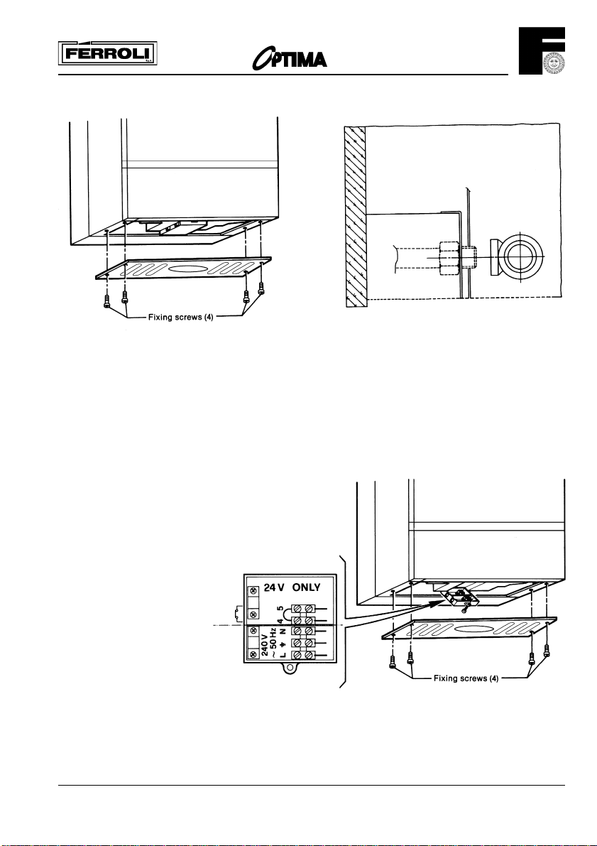
5.2 Remove the boiler base plate, four screws (fig. 11). Remove the plugs fitted to the boiler water
connections.
Remove the bag of sealing washers from the boiler pipework. Remove the front panel by gripping
on both sides and pulling away from the main boiler.
5.3 Lift boiler as shown in fig. 10 onto the top studs and fit supplied nuts and washers hand tight.
5.4 Lift at bottom to engage the water and gas connections. Tighten central heating flow and return,
and the domestic hot water inlet and outlet, using appropriate sealing washers. Tighten the gas union.
5.5 Connect the pressure relief valve discharge pipe (15 mm) to the outside of the building, where possible
over a drain. The discharge must be such that it will not be hazardous to occupants or passers-by or
cause damage to external electric components or wiring. The pipe should be directed towards the wall.
It must not discharge above an entrance or window, or any type of public access. The installer must
consider that the overflow could discharge boiling water.
16
Fig. 10
Page 17
201
Fig. 11
Fig. 12
4.0 ELECTRICAL INSTALLATION
Electrical installation must be carried out by a competent electrician. The appliance is to be connected
to a 240 V ~ 50 Hz supply (see fig. 13). The supply fuse rating is 3A. The terminals are accessible
after removing the boiler base plate and single screw securing the terminal cover (see fig. 13).
External controls: room stat or
remote time clock in the place of
loop terminals 4 and 5. Please
note 24 V only.
Fig. 13
17
Page 18
201
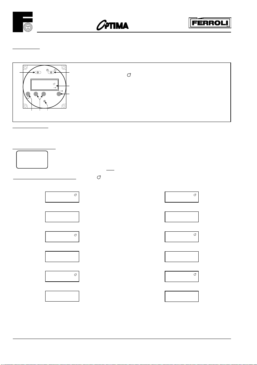
Time Clock
A 24 hour time clock is fitted to the boiler to control the central heating, this will come into operation when the selector
switch is turned to the position marked “heating timed and hot water”.
AUTO
AUTO
P
12:31
+
P
Display
Display
Display
Display
Display
Display
OI
-
R
RDP
4
x
x
OVER RIDE
-
adjust until the correct time is shown on display (B).
6:30
8:30
12:00
12:00
16:30
22:30
F
To set time of day
1. Slide switch (A) to left position
2. Using button + and
Pre Set Programmes. The timer is pre programmed with 3 ON and 3 OFF times.
6:30 - 8:30
12:00 - 12:00
16:30 : 23:30
To Set Own ON and OFF times. Symbol in Display = ON time
1. Slide switch (A) to right position (P)
2. Press button (P)
3. Press button (P)
4. Press button (P)
5. Press button (P)
6. Press button (P)
7. The timer can be programmed with up to 8 ON and
8 OFF times by repeating the above procedure.
A Slide switch: set clock - auto - set programme
A
B Display. Symbol in Display = Timer ON
P Select programme ON/OFF 1.....8
B
D Push buttons Time + Time
E
E Override: Boiler will switch ON if boiler is OFF;
and OFF if is ON
F I=Heating continuous - AUTO=Heating timed - O=Heating disabled
R Reset (with pencil) only with switch A in set clock position
If these are suitable no programming is required and the slide switch (A) can be
moved to the Auto position and the central heating will be ON for these periods.
(12:00 - 12:00 will not switch on the boiler)
1
2 9:00
3
4
5
6
-
1.1 Use buttons + and - to set 1st ON time eg. 6:00
Display
2.1 Use buttons + and - to set OFF time, eg. 9:00
Display
3.1 Use button + and - to set 2nd ON time, eg. 12:30
Display
4.1 Use button + and - to set 2nd OFF time eg. 14:00
Display
5.1 Use button + and - to set 3rd ON time, eg. 16:00
Display
6.1 Use button + and - to set 3rd OFF time eg. 23:30
Display
8. On completion of programming slide switch (A) to Auto
position, the time of day will be displayed and the central heating will switch ON and OFF according to the
programme set.
6:00
12:30
14:00
16:00
23:30
1
2
3
4
5
6
18
Page 19
201
Over ride
By pressing the over ride button (E) the timer programme is over ridden ie, if programme is in OFF
time it will come ON and if in ON time will go OFF.
The timer will revert back to it set programme on reaching the next ON or OFF time.
When the programme is on over ride the sign will be shown in the display window (B).
Reset Button
By the use of a pencil the reset button can be pushed (R). This will clear all programmes apart from
those factory pre set.
Reset is only possible with switch (A) in set Clock position!
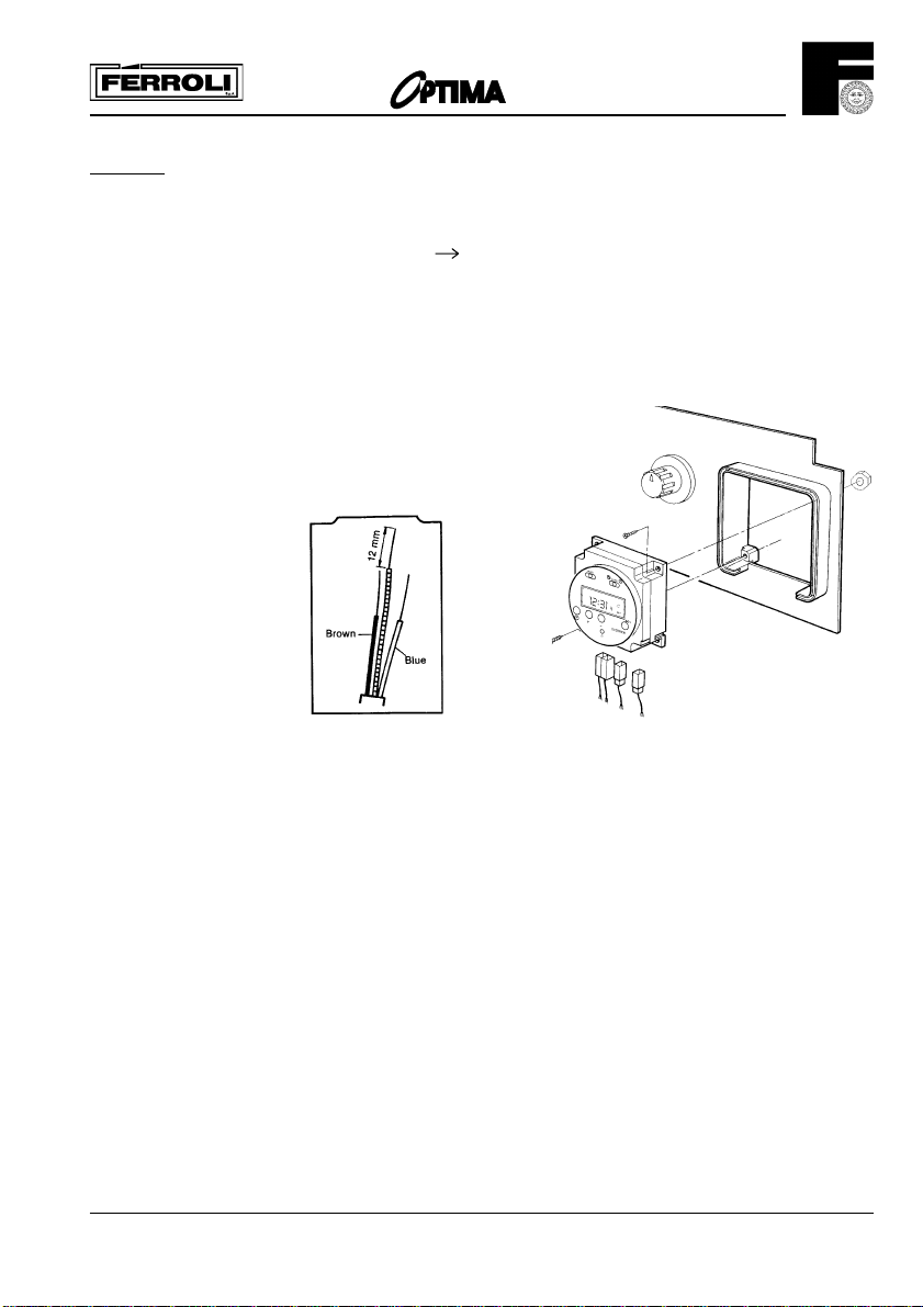
12.0 REMOVAL OF THE CLOCK
a) Refer to section 1, items a, c, d, f and j.
b) Disconnect the electrical connections to the time clock.
c) Remove the time clock from the control panel (fig. 43).
d) Re-assemble in reverse order (refer to fig. 43 for replacement of
the time clock).
Fig. 14
4.1 Procedure
4.1.1 The supply cable must not be no less than 0.75 mm (24x0.2
mm) to BS6500 table 16.
4.1.2 The earth conductor must be cut longer than the live and neutral (fig. 14).
Connect the Supply Cable to the terminal block marked 240 V ~ 50 Hz, L, N, the supply cable is to be connected
as follows:
i) Connect the brown wire to the L (live) terminal).
ii) The blue wire to the N (neutral) terminal.
iii) The green/yellow wire to the (earth) terminal.
4.1.3 Secure the cable with the cable clamp.
The supply cable can be connect to the mains supply by the use of an unswitched shuttered socket-outlet in
conjunction with the 3A fused 3 pin plug both in accordance with BS 1363. This provides complete isolation.
Alternatively, a fused double pole switch having a contact separation of at least 3 mm, in all poles and provided
just for the boiler and its external controls can be used.
A wiring diagram is provided on the appliance, attached to the rear of the front panel. In addition, there is
one in this manual (fig. 20b).
Attention is drawn to the requirements of the current I.E.E. Regulation and in Scotland, the electrical provisions
of the Building regulations.
4.2 Room Thermostat (fig. 18) (or remote time clock connection)
4.2.1 Please note that the room thermostat, clock switch connection is 24 V.
To connect mains voltage to these terminals will seriously damage the printed circuit board.
The room thermostat and clock switch connector block is situated within the connector box. Twin core cable
should be used for this connection (terminals 4 and 5).
4.2.2 If using a remote 240 Volt time clock ensure that the motor and switch connections are totally separate in
the clock and that the switch connections are independent for the 24 Volt terminals (4 and 5) on the boiler.
x
19
Page 20
8.0 COMMISSIONING AND TESTING
201
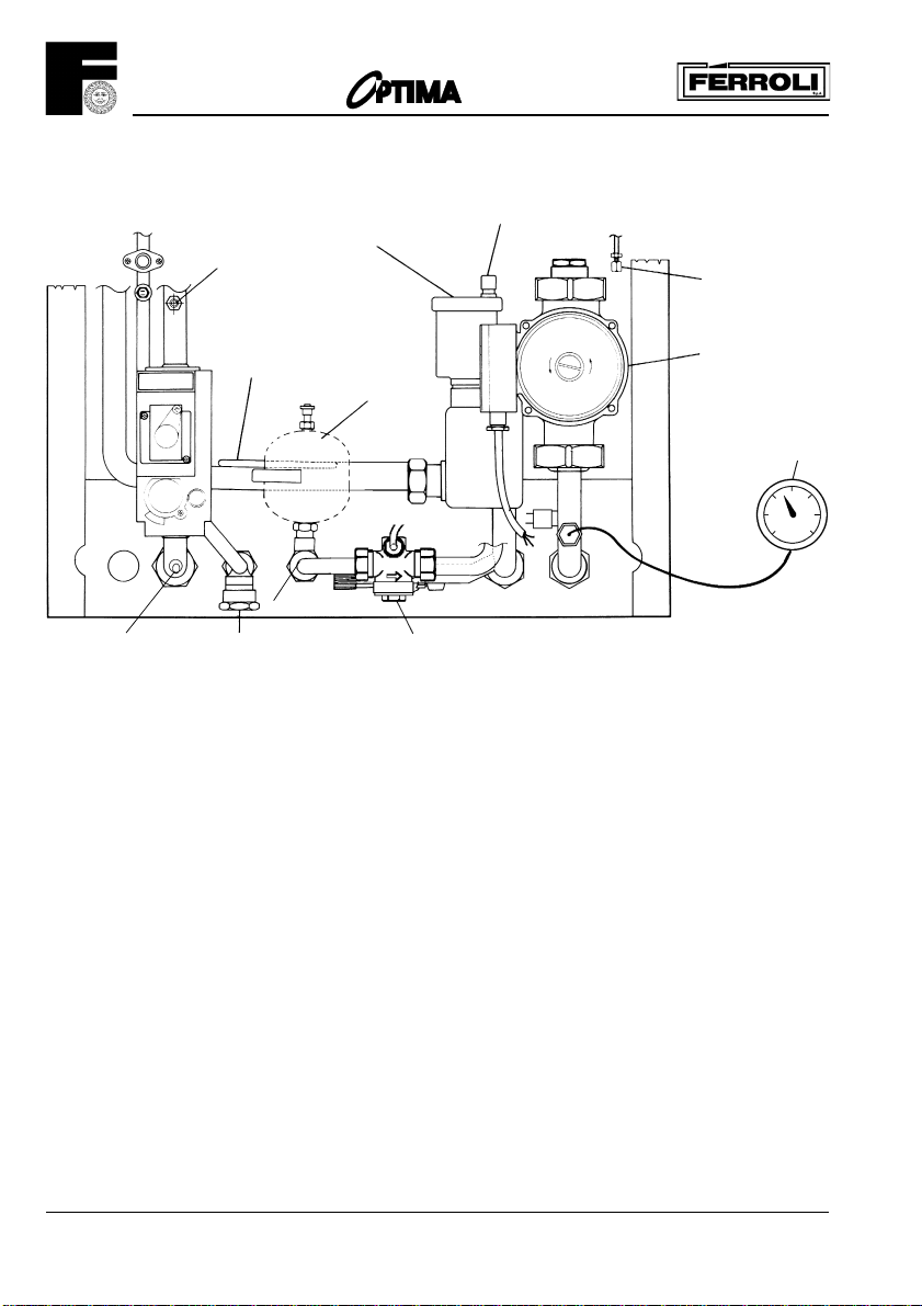
8.1 Filling the Central Heating System
Automatic air vent
D.H.W. expansion
vessel (optional)
Gas inlet pressure
test point
Burner pressure
test point
C.H. temperature sensor
phial and shim
D.H.W. drain point
C.H. pressure relief valve
(at the rear of cold
water flow switch)
Plastic cap
Heat exchanger vent
Pump
Remove the top front panel by gripping both sides and pulling forward away from main boiler assembly.
Loosen the cap of the automatic air vent (fig. 15) and leave it loose.
Open the central heating flow and return cocks (fig. 9).
Gradually fill the system as detailed in Make up Water.
While filling, vent the heat exchanger at venting point by loosening cap (fig. 15) on the right hand side
and vent each radiator. Tighten cap on heat exchanger air vent, but be sure to leave loose the plastic
cap on the automatic air vent.
Ensure the working pressure, when filled, is between 1 an 1.5 bar on the pressure gauge (see technical
data).
Check the system for leaks.
Flush system in accordance with B.S. 7593.
8.2 Filling the Domestic Hot Water System
Close all hot water draw off points. Open main cold water stop cock and ensure the cold water inlet
cock is open at the boiler jig bracket (fig. 9). Slowly open each hot tap in turn until clean water, free from
air pockets, is seen.
Check system for leaks.
8.3 Electricity Supply
Carry out preliminary checks (i.e. earth continuity, polarily short circuit and resistance to earth
using a suitable multimeter).
8.4 The Gas Installation
The whole of the gas installation including the meter, should be inspected and tested for soundness,
and purged in accordance with the recommendations of BS6891-1988.
Pressure gauge
Fig. 14
20
Page 21
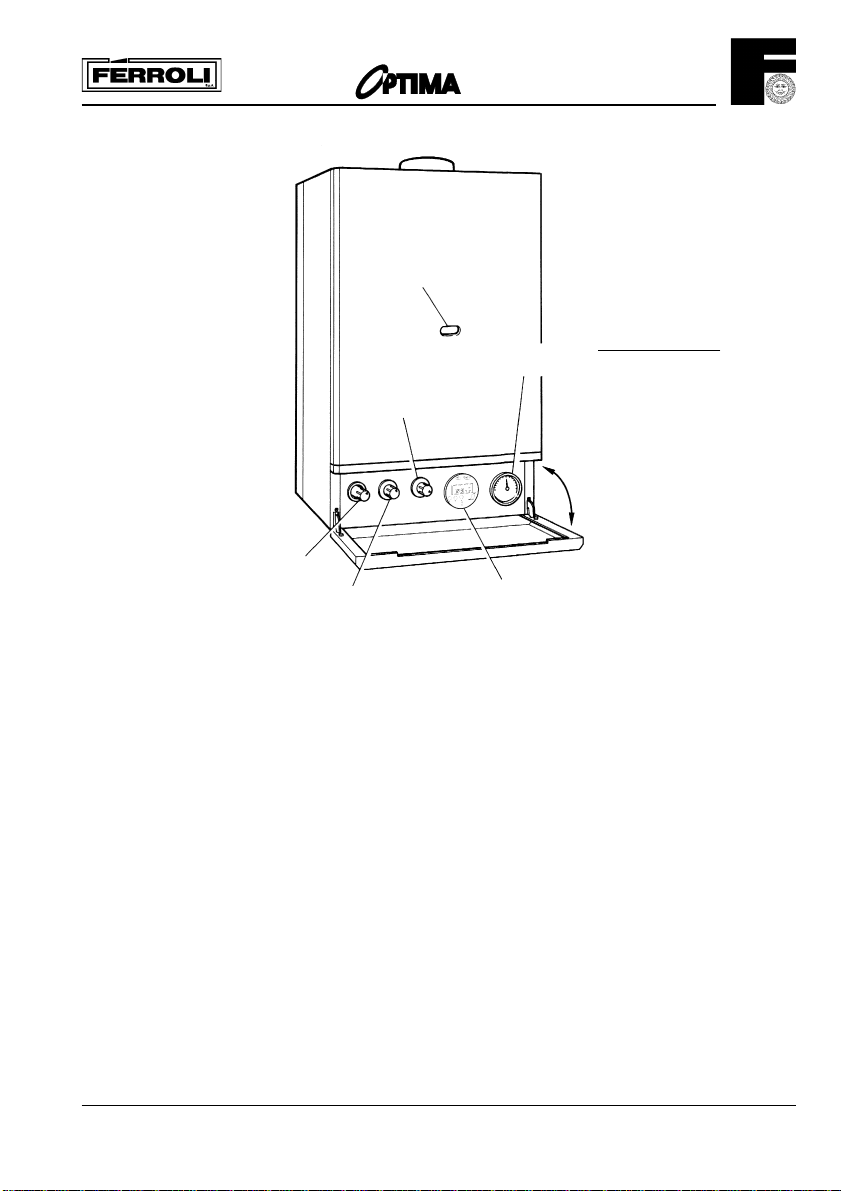
C.H. valve
control knob
5.5 To Light the Boiler (fig. 16)
Pilot viewing
opening
C.H. boiler
thermostat
C.H./D.H.W. selector switch
Fig. 16
201
C.H. pressure gauge
Time clock
Important note If the burner stops for C.H.
only after a waiting time
of 3 minutes the boiler will
light again!
1. Open controls panel door by pulling at either side.
2. Ensure that the C.H./D.H.W. selector switch is set for heating continuous and Hot Water.
3. Ensure that the electricity supply is turned on.
4. Ensure that the heating system is filled with water and has not been drained down.
(pressure gauge should read 1.0 bar minimum).
5. Adjust room thermostat (if fitted) to a high setting.
6. Adjust the boiler thermostat to its maximum setting, wait 3 minutes before continuing.
7. Depress the gas control knob fully (this should operate the electronic ignitor). When the pilot
flame is seen to light through the pilot viewing window, keep the control knob fully depressed for a
further 15 seconds, then release.
Should the pilot fail to remain alight (or go out for any reason), then wait a full 3 minutes before
attempting to relight
the pilot. Should the pilot still fail to remain alight, turn the boiler off and contact your installer.
8. With the pilot burner established, observe that the main burners cross-light smoothly.
9. Set the time clock, room thermostat (if fitted) and the boiler thermostat to their desired settings.
Note 1 - The main burner will light whenever a hot tap is turned on.
Note 2 - If the electricity supply is switched off for any reason, ensure that the pilot burner has remained
alight. if the boiler has gone out, follow "The boiler lighting instructions" for relighting it.
21
Page 22
201
P2P1
MIN
MAX
MIN
MAX
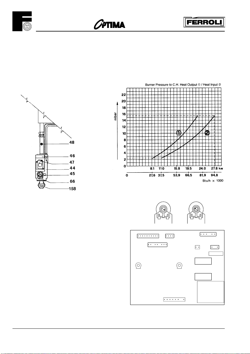
5.6 To Range Rate the Boiler C.H. (not required on standard installation)
The boiler can be range rated for an output up to 23.3 kW. When the boiler is supplied it is factory set
at an output 23,3 kW.
Procedure
a. Release the control panel fixing screws (fig. 23) and lower panel.
b. Loosen the screw in the burner pressure test point (fig. 17) and attach a gauge.
c. Ensure C.H./D.H.W. selector switch is set for heating continuous and hot water.
d. Adjust room thermostat to maximum (if fitted).
e. Turn boiler thermostat to maximum.
Fig. 18
Fig. 17
Key
44 Combination gas valve
45 Knob gas valve
46 operator gas valve
47 Modulating regulator (Modureg) gas valve
48 Burner pressure test point
66 Microswitch
158 Gas inlet pressure test point
Note 1 - Modulation is available on central heating, so the
procedures must be carried out while the system is relatively
cold. Recheck boiler thermostat is set to maximum.
d. Adjust the potentiometer P1 on the PCB (fig. 19) in the
control panel until the required burner pressure is obtained
(Anticlockwise to reduce the pressure).
P1 =C.H. range rating to be set on site
P2 =D.H.W. temperature (factory set, not to be adjusted)
P1 Adjust with screwdriver!
Fig. 19
12 1
11 10
9876543
X1
13
P1
234
X2
76512 910
X3
P2
X4
2
X7
RY1
12
6 5
1
341
230V
50Hz
X6
2AT
F1
Note 2 - The range of inputs with corresponding burner
pressure is given on the Data badge which is situated
behind the top front panel. Further informations is on (fig.
18).
e. With the pressure set, turn off the electrical supply and
mark the set input on the Data badge (with sticker supplied).
Burner Pressure C.H. and D.H.W.
22
RY2
X8
TR1
Page 23
201
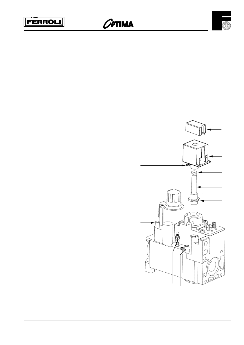
Honeywell VR 4600 N 4002 valve
with V7335A4014 Modureg
Gas pressure Adjustment
1 - With the burner lit:
2 - Connect suitable pressure gauge to burner test point "B", and then:
3 - Disconnect the wires from coil "C" of the Modureg;
4 - Remove protective cover "D";
5 - Remove coil "C" by opening the coupling spring "I";
6 - Screw the minimum adjustment screw "E" up tightly. (clockwise)
7 - Unscrew lock nut "F" on sleeve "G";
8 - Adjust maximum pressure by rotating sleeve "G"
clockwise to increase pressure and anticlockwise
to reduce pressure;
9 - Tighten sleeve lock but "F" then check that the
pressure is still at the required value;
10 - Adjust minimum pressure by rotating screw "E"
anticlockwise until the required value is reached;
11 - Fit coil "C" by sliding it into the sleeve, pushing and
rotating it lightly until the coupling spring "I" clicks
into place;
12 - Shut down and ignite the burner, checking that the
minimum pressure value is stable;
13 - Reconnect the wires to coil "C" of the Modureg;
14 - Replace protective cover "D";
15 - Turn burner off, remove pressure gauge, close and
test, test point;
I
D
C
E
G
F
Key
A - Test point inlet pressure
B - Burner test point
C - Coil
D - Protective cover
E - Minimum adjustment screw
F - Lock nut
G - Sleeve
I - Coupling spring
L - Adapter (for only G.L.P. version)
A
L
B
23
Page 24

201
f. Switch on the electricity supply to relight the main burner.
5.7 D.H.W. Burner Pressure
The domestic hot water burner pressure in not range rateable and not adjustable but the maximum and
minimum burner pressure should be checked as follows:
a. Check electricity supply is still off.
b. Open a D.H.W. tap at high flow until the water runs cool and leave running.
c. Switch on the electricity supply.
d. The pressure should be 14.5 mbar -/+ 0.5 mbar.
e. Disconnect one of the wires from the «Modureg» (fig. 17), this will reduce the burner to minimum
which should read 2.7 mbar +/- 0.5 mbar. If the burner pressure is not as stated check the inlet
working pressure (fig. 17) which should be minimum 20 mbar. If that is correct, consult Ferroli
SERVICE DEPARTMENT. No attempt should be made to alter D.H.W. burner pressure.
f. Switch off electrical supply and close hot tap.
g. Reconnect the wire to the «Modureg». Remove pressure gauge, tighten the test screws.
h. Replace control panel (2 screws).
i. Turn on electricity supply, open a hot tap to full flow and when the burner lights, test for gas soundness
with a leak detection fluid around the gas valve and connections indluding the pressure test point
screws.
Note - The cutting of the electricity supply may result in the pilot being extinguished - re-light if need be,
after waiting three minutes at least.
6.0 SYSTEM OPERATION
Let the boiler operate normally on central heating for about 30 minutes.
I) Vent radiators.
II) Vent heat exchanger.
III) Examine all pipework for leakage.
IV) Turn on a D.H.W. tap and check that the C.H. pump stops running.
V) As the D.H.W. temperature reaches 60°C check the burner for modulation.
VI) Carry out a spillage test in accordance with BS5440 Part 1.
Turn the gas valve «off», (twist the plastic knob 1/12th turn clockwise and release), and isolate electricity
supply.
Drain down the central heating system fully, when hot to flush out flux, etc. Refill the system as previously
instructed. Repeat the venting. Examine the system's water pressure and topo up as necessary.
Replace the casing front panel and close the control panel cover.
7.0 HANDING OVER TO THE USER
After completion of installation and commissioning of the system:
a. Hand over the User's Instructions' to the Householder and explain His/Her responsability under the Gas
safety (Installation and Use) Regulations 1984.
b. Explain and demonstrate the lighting and shutting down procedure.
c. Explain the operation of the boiler including the use and adjustment of ALL system controls.
Advise the User of the precautions necessary to prevent damage to the system and to the building,
in the event of the system remaining inoperative during frost conditions.
d. Stress the importance of regular servicing by a qualified Heating Engineer and that a comprehensive
service should be carried out at LEAST ONCE A YEAR.
24
Page 25
201
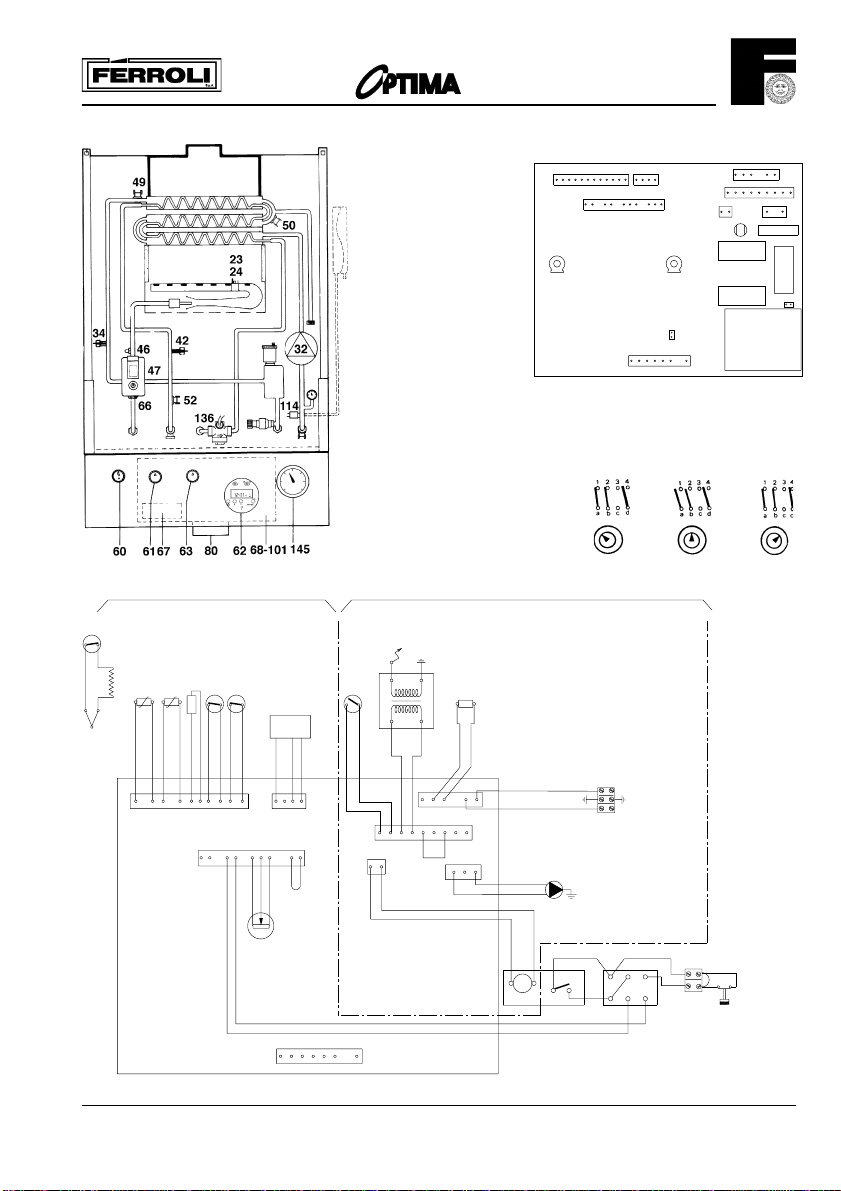
Key
23 Thermocouple
24 spark electrode
32 Central heating pump
34 C.H. flow temperature sensor
42 D.H.W. temperature sensor
46 Operator gas valve
47 Modulating regulator
(Modureg) gas valve
49 Overheat cut-off thermostat
50 Heat exchan. limit thermostat
52 D.H.W. limit thermostat
60. Extended control kob to gas valve
61 C.H. selector switch
62 Time clock
63 C.H. boiler thermostat
66 Microswitch combination
gas valve
67 Ignition transformer
68. Control box with P.C.B.
72 Room thermostat (not fitted)
80 240V + 24V roomstat terminal blocks
101 P.C.B.
114 Water pressure switch
136 Flowmeter
145 C.H. pressure switch
61. C.H. selector switch
Heating timed and hot water
12 1
11 10
987654321
X1
P1
7263512 910
13
X8
P1 = C.H. max. output
(to be set on site)
P2 = D.H.W. temperature
(factory set)
J1 Jumper links on P.C.B.
JP1 Must is not required
6 5
12
234
X2
1
X3
P2
X4
X5
2
X7
L7
RY1
RY2
JP1
TR1
230V
50Hz
123456789
341
1
X6
2AT
F1
RY4
JP4
24 V
220V ~ 50 Hz.
Hot water only
Heating
continuous and hot water
49
24
47
114
34
42
50
136
+
23
X1
12
10
1
10 9 5 362713
OUT
X2
34825-6791
34
1
812
X3
21
66
L
X5
9
X7
21
46
N
67
X4
6
4125
678
31245
80
L
220V
N
X6
213
32
63
4
M
1 5
2
3
X8
VMF7
2
1
4
d
b
a
24V
5
80
72
25
Page 26
201
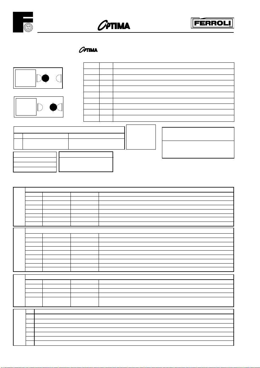
General Notes - For use on the
201 fitted with VMF7 Printed Circuit Board
*The central heating pump (32) will run to disperse heat if the temperature at the heat exchanger limit thermostat (50) is too high
RL not energised
RL energised
Jumpers J1 - J2
Fitted Not fitted
J1 Prepurge time before Prepurge time before
ignition = 0 second ignition = 20 second
RELAYS
RL1 central heating pump
RL2
RL3 ignition
NOTE
If RL1 is not energised the
Central Heating pump will
run
LED n° colour signification:
1 green Mains on/low voltage on
2 yellow Domestic hot water flow switch (38) on
3 yellow Central heating room thermostat (72) / clock (62) calling for heat
4 green Sensor (34) or (42) calling for heat
5 red Central Heating waiting time, a max. 3 minutes delay following
6 yellow Demand for heat. Relays RL2/RLX energised.
7 green Demand for heat
8 yellow Gas valve (46) energised
shut off Boilerstat (63), Clock (62), Roomstat (72) or use of Hot Water
J1 should
be fitted
REsistance of Central Heating
or Hot Water sensors
10° C 890 ohm
25° C 1000 ohm
60° C 1300 ohm
(34) + (42)
Check operation using LED's as a fault finding guide. First check section A, then B, then C, then D.
0 = LED off 1 = LED on x = LED either on/off is not important
Domestic Hot water tap open (Flow rate greater than 2,5 l/min)
LED OK FAULT POSSIBLE CAUSE OF FAULT
1 1 0 No mains electricity/switches off/fuse blown.
2 1 0 D.H.W. flow switch (38) not operating.
3 X X Not required for D.H.W.
A
4 1 0 - D.H.W. sensor (42) not connected or D.H.W. temperature too high
5 0 1 - Waiting time operating: replace P.C.B.
6 1 0 Short circuit on D.H.W. sensor (42) or resistance lower than 500 Ohm
CENTRAL HEATING ON Room stat (72) at Max, HW tap closed
LED OK FAULT POSSIBLE CAUSE OF FAULT
1 1 0 No main electricity/switches off, fuse blown.
2 0 1 Hot water tap open - D.H.W. flow switch (38) contact closed
3 1 0 Roomstat (72) or clock (62) not calling for heat
4 1 0 - Central heating sensor (34) not connected or
B
5 0 1 Waiting time still operating (max. 3 minutes)
6 1 0 - C.H. sensor (34) short circuit or resistance lower than 500 ohm
GENERAL TEST FOR D.H.W. AND CENTRAL HEATING (First check A and B above)
RL2/RLX energised not energised Wiring defect: check wiring on (66-67-68)
LED 7 1 0 Wiring defect: check wiring on (66-67-68)
C
LED 8 1 0 - CH limit thermostat (50) open circuit (pump will run)
1 Check first A, B and C above
2 Check if Jumper J1 is fitted
3 Push ignition button (60) fully in
D
4 Microwitch (66) will close
5 Relay RL3 will energise
6 Ignition transformer (67) will energise
7 Check spark and position of spark electrode (24)
OK FAULT POSSIBLE CAUSE OF FAULT
IGNITION OF PILOT
- boiler temperature too high or
- boiler thermostat (63) below CH temperature
- DHW limit thermostat (52) open circuit
26
Page 27
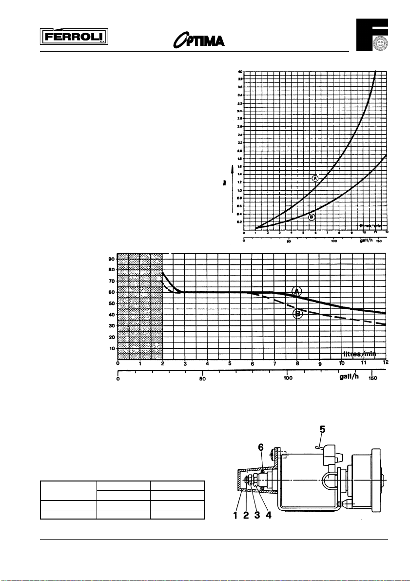
Domestic Hot Water Performance
Fig. 1 - D.H.W. Pressure Drop VS. flow
A=Standard with col water Flow Restricter
B=Cold Water Flow Restricter Removed
Fig. 2 - D.H.W.
temperature VS. flow
A=Cold Water 15°C
B=Cold Water 5°C
201
Fig. 1
Modulating regulator (Modureg) of gas valve
1. Cap (with tube 71)
2. Shaft
3. Adjustment screw for max. pressure setting
4. Adjustment screw for min. pressure setting
5. 6,3 mm APM terminals
6. «O» ring
If necessary replace complete MODUREG
Pressure Minimum Maximum
settings mbar mbar
Natural Gas 2.7 14.5
L.P.G. 7.9 36.0
Fig. 2
27
Page 28
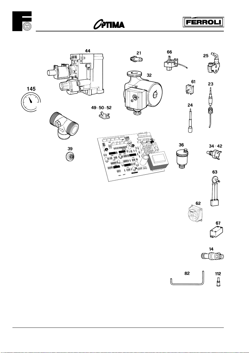
201
136
101
Spare Parts List
Item No.G.C. Part No.Makers Part No No. Off DESCRIPTION
14 386816 800130 1 C.H. safety valve
21 372176 815850 4 Main injector (Natural Gas)
21 - 815870 4 Main injector (L.P.G.)
23 390210 801170 1 Thermocouple
24 386575 801890 1 Spark electrode
25 386586 801900 1 Pilot
32 386814 800620 1 Central heating pump
34 386818 800310 2 Temperature sensor
36 394246 801160 1 Automatic air vent
39 386829 801220 1 Cold water flow limiter
42 386818 800310 2 Temperature sensor
44 386544 803450 1 Combination gas valve
49 386815 801240 1 Overheat cut-off thermostat
50 386577 800160 1 Heat exchanger limit thermostat
52 386576 801000 1 D.H.W. limit thermostat
61 372225 801230 1 C.H.selector switch
62 - 803830 1 Time clock
63 372224 801260 1 C.H. boiler thermostat
66 372320 801370 1 Microswitch combination gas valve
67 372309 801150 1 Ignition transformer
101 372306 803410 1 P.C.B. VMF7
112 386573 810570 1 Pilot injector (Natural Gas)
112 - 810660 1 Pilot injector (L.P.G.)
136 - 803430 1 Flowmeter
145 - 803890 1 C.H. pressure gauge
28
Page 29

201
29
Page 30

Page 31

Page 32

Phone numbers:
Installer
Service Engineer
BECAUSE OF OUR CONSTANT ENDEAVOUR FOR IMPROVEMENT DETAILS
MAY VARY SLIGHTLY FROM THOSE QUOTED IN THESE INSTRUCTIONS.
ALL SPECIFICATIONS SUBJECT TO CHANGE
Lichfield Road, Branston Industrial Estate, Burton Upon Trent, Staffordshire DE14 3HD
Tel. 08707 282 885 - Fax 08707 282 886
cod. 3540256/1 - 01/01
 Loading...