

Ferroli OMNIA H 04E, OMNIA H 06E, OMNIA-UE 04, OMNIA HI3 04E, OMNIA-UI H 08 Installation, Maintenance And User Manual
...
1
R
E
F
R
I
G
E
R
A
N
T
G
A
S
E
C
O
-
F
R
I
E
N
D
L
Y
OMNIA H
REVERSIBLE HEAT PUMP
FOR SPLIT INSTALLATION
INSTALLATION, MAINTENANCE AND USER MANUAL
EN

2
• Read the warnings in this instruction booklet carefully
since they provide important information on safe installation, use and maintenance.
• This instruction booklet is an integral and essential part
of the product and must be kept with care by the user
for future reference.
• If the unit is sold or transferred to another owner or if
it is to be moved, always make sure the booklet stays
with the boiler so that it can be consulted by the new
owner and/or installer.
• Installation and maintenance must be carried out by
professionally qualified personnel, according to current
regulations and the manufacturer's instructions.
• Incorrect installation or inadequate maintenance can
result in damage or injury. The manufacturer declines
any liability for damage caused by errors in installation
and use or by failure to follow the instructions provided.
• Before carrying out any cleaning or maintenance ope-
ration, disconnect the unit from the power supply using
the system switch and/or the special cut-off devices.
• In case of a fault and/or poor operation, deactivate
the unit and do not try to repair it or directly intervene.
Contact professionally qualified personnel. Any repair/
replacement of the products must only be carried out
by qualified personnel using genuine parts. Failure to
comply with the above cancompromise the safety of
the unit.
• Periodic maintenance performed by qualified person-
nel is essential in order to ensure proper operation of
the unit.
• This unit must only be used for its intended purpose.
Any other use is deemed improper and therefore hazardous.
• After unpacking, check the good condition of the con-
tents. The packing materials are potentially hazardous
and must not be left within the reach of children.
• The unit can be used by children aged at least 8 ye-
ars and by persons with reduced physical, sensory or
mental capabilities, or lacking experience or the necessary knowledge, only if under supervision or they have
received instructions on its safe use and the related
risks. Children must not play with the unit. Cleaning
and maintenance intended to be done by the user can
be carried out by children aged at least 8 years only if
under supervision.
• In case of doubt, do not use the unit. Contact the sup-
plier.
• The unit and its accessories must be appropriately di-
sposed of in compliance with current regulations.
• The images given in this manual are a simplified re-
presentation of the product. In this representation there
may be slight and insignificant differences with respect
to the product supplied.
The CE marking certifi es that the products meet the essential requirements of the relevant directi-
ves in force.
The declaration of conformity may be requested from the manufacturer.
This symbol indicates "Caution" and is placed next to all safety warnings. Strictly follow these instructions
in order to avoid danger and damage to persons, animals and things.
☞
This symbols calls attention to a note or important notice.
This symbol, which is used on the product, packaging or documents, means that at the end of its useful
life, this product must Mnot be collected, recycled or disposed of together with domestic waste.
Improper management of electric or electronic waste can lead to the leakage of hazardous substances
contained in the product. For the purpose of preventing damage to health or the environment, users are
kindly asked to separate this equipment from other types of waste and to ask for it to be dealt with by
the municipal waste service or dealer under the conditions and according to the methods set down in
national and international laws transposing the Directive 2012/19/EU.
Separate waste collection and recycling of unused equipment helps to save natural resources and to
guarantee that this waste is processed in a manner that is safe for health and the environment. For
more information about how to collect electric and electronic equipment and appliances, please contact
your local Council or Public Authority competent to issue the relevant permits.
Proper uses
This series of heat pumps is designed to produce cold or hot water for use in hydronic systems for conditioning/heating
purposes and the production of domestic hot water in an indirect way through a storage tank and a heat exchanger.
Any use differing from this proper use or beyond the operating limits indicated in this manual is forbidden unless previously
agreed with the manufacturer.

3
THIS MANUAL IS DIVIDED INTO SECTIONS. THEIR NAMES APPEAR IN THE HEADING OF EACH PAGE.
SUMMARY
The manufacturer declines all responsibility for any inaccuracies in this manual due to printing or typing errors.
The manufacturer reserves the right to modify the products contents in this catalogue without previous notice.
GENERAL FEATURES . . . . . . . . . . . . . . . . . . . . . . . . . . . . . 4
European Directives . . . . . . . . . . . . . . . . . . . . . . . . . . . . . 4
Identification plate of the Units . . . . . . . . . . . . . . . . . . . . . 4
Presentation of the system . . . . . . . . . . . . . . . . . . . . . . . . 5
Unit identification code . . . . . . . . . . . . . . . . . . . . . . . . . . . 5
Abbinamenti unità esterna con unità interna . . . . . . . . . . 5
Components supplied with the indoor unit . . . . . . . . . . . . 6
The control system . . . . . . . . . . . . . . . . . . . . . . . . . . . . . . 6
Components supplied with the outdoor unit . . . . . . . . . . . 6
TECHNICAL DATA AN PERFORMANCE . . . . . . . . . . . . . . . 7
System technical data. . . . . . . . . . . . . . . . . . . . . . . . . . . . 7
DIMENSIONAL AND PHYSICAL DATA . . . . . . . . . . . . . . . . 8
Available static pressure. . . . . . . . . . . . . . . . . . . . . . . . . . 8
Operating limits. . . . . . . . . . . . . . . . . . . . . . . . . . . . . . . . . 8
Overall dimensions indoor unit . . . . . . . . . . . . . . . . . . . . . 9
INSTALLATION . . . . . . . . . . . . . . . . . . . . . . . . . . . . . . . . . . . 11
Inspections on arrival . . . . . . . . . . . . . . . . . . . . . . . . . . . . 11
Packing and storing . . . . . . . . . . . . . . . . . . . . . . . . . . . . . 11
Cooling connections indoor unit . . . . . . . . . . . . . . . . . . . . 14
Tips for a successful installation . . . . . . . . . . . . . . . . . . . . 17
Water filter. . . . . . . . . . . . . . . . . . . . . . . . . . . . . . . . . . . . . 17
Water component for corrosion limit . . . . . . . . . . . . . . . . . 17
Water pipework. . . . . . . . . . . . . . . . . . . . . . . . . . . . . . . . . 17
Protecting the water circuit against freezing . . . . . . . . . . 18
Filling with water . . . . . . . . . . . . . . . . . . . . . . . . . . . . . . . . 19
Piping insulation . . . . . . . . . . . . . . . . . . . . . . . . . . . . . . . . 19
Electrical conections indoor unit . . . . . . . . . . . . . . . . . . . . 20
Electrical conections outdoor unit . . . . . . . . . . . . . . . . . . . 21
Electrical connections . . . . . . . . . . . . . . . . . . . . . . . . . . . . 22
Connessioni tra morsettiera unità interna e componenti
d'impianto . . . . . . . . . . . . . . . . . . . . . . . . . . . . . . . . . . . . . . . . 23
How to go to FOR SERVICEMAN . . . . . . . . . . . . . . . . . . 25
"FOR SEVICEMAN" menu . . . . . . . . . . . . . . . . . . . . . . . . 26
DHW mode setting . . . . . . . . . . . . . . . . . . . . . . . . . . . . . . 30
Tank heater (electrical heater for DHW tank) . . . . . . . . . . 31
Disinfect . . . . . . . . . . . . . . . . . . . . . . . . . . . . . . . . . . . . . . 31
DHW priority . . . . . . . . . . . . . . . . . . . . . . . . . . . . . . . . . . . 32
DHW pump ricircolo . . . . . . . . . . . . . . . . . . . . . . . . . . . . . 32
COOL mode setting . . . . . . . . . . . . . . . . . . . . . . . . . . . . . 33
HEAT mode setting . . . . . . . . . . . . . . . . . . . . . . . . . . . . . . 34
AUTO mode setting . . . . . . . . . . . . . . . . . . . . . . . . . . . . . 35
Temp. Type setting (to activate the internal temperature probe
of the controller as room thermostat) . . . . . . . . . . . . . . . . . . . 35
Room thermostat (ON/OFF - HEAT/COOL by digital input) . 36
Other heating source . . . . . . . . . . . . . . . . . . . . . . . . . . . . 37
Backup heater (electrical booster) . . . . . . . . . . . . . . . . . . 37
AHS (Additional Heating Source, gas bolier) . . . . . . . . . . 38
Indoor unit DIP switch settings . . . . . . . . . . . . . . . . . . . . . 39
Holiday away setting. . . . . . . . . . . . . . . . . . . . . . . . . . . . . 40
Service call . . . . . . . . . . . . . . . . . . . . . . . . . . . . . . . . . . . . 40
Restore factory settings . . . . . . . . . . . . . . . . . . . . . . . . . . 40
Special function . . . . . . . . . . . . . . . . . . . . . . . . . . . . . . . . 41
Auto restart . . . . . . . . . . . . . . . . . . . . . . . . . . . . . . . . . . . . 42
Parameters list . . . . . . . . . . . . . . . . . . . . . . . . . . . . . . . . . 43
MESSA IN FUNZIONE. . . . . . . . . . . . . . . . . . . . . . . . . . . . . . 44
Starting up for the first time. . . . . . . . . . . . . . . . . . . . . . . . 44
Preliminary checks on the electrical part . . . . . . . . . . . . . 44
Preliminary checks on the cooling part . . . . . . . . . . . . . . . 44
Pre-operation checks . . . . . . . . . . . . . . . . . . . . . . . . . . . . 44
Final check . . . . . . . . . . . . . . . . . . . . . . . . . . . . . . . . . . . . 44
Powering up the unit . . . . . . . . . . . . . . . . . . . . . . . . . . . . . 44
CONTROL SYSTEM . . . . . . . . . . . . . . . . . . . . . . . . . . . . . . . 45
The appearance of the wire control device. . . . . . . . . . . . 45
The overview pages available user . . . . . . . . . . . . . . . . . 46
Home page . . . . . . . . . . . . . . . . . . . . . . . . . . . . . . . . . . . . 49
Screen Unlock . . . . . . . . . . . . . . . . . . . . . . . . . . . . . . . . . 50
Turning ON/OFF controls . . . . . . . . . . . . . . . . . . . . . . . . . 50
Adjusting the temperature . . . . . . . . . . . . . . . . . . . . . . . . 51
Adjusting space operation mode (heat/cool) . . . . . . . . . . 52
About the menu structure . . . . . . . . . . . . . . . . . . . . . . . . . 52
To go to the menu structure . . . . . . . . . . . . . . . . . . . . . . . 52
Operation Mode . . . . . . . . . . . . . . . . . . . . . . . . . . . . . . . . 53
Preset temperature . . . . . . . . . . . . . . . . . . . . . . . . . . . . . 53
Domestic Hot Water (DHW) . . . . . . . . . . . . . . . . . . . . . . . 55
Schedule. . . . . . . . . . . . . . . . . . . . . . . . . . . . . . . . . . . . . . 57
Options . . . . . . . . . . . . . . . . . . . . . . . . . . . . . . . . . . . . . . . 59
Child lock . . . . . . . . . . . . . . . . . . . . . . . . . . . . . . . . . . . . . 61
Service information . . . . . . . . . . . . . . . . . . . . . . . . . . . . . . 62
Operation Parameter . . . . . . . . . . . . . . . . . . . . . . . . . . . . 63
For Serviceman . . . . . . . . . . . . . . . . . . . . . . . . . . . . . . . . 63
Weather temperature set for cool mode . . . . . . . . . . . . . . 64
Weather temperature set for heat mode. . . . . . . . . . . . . . 64
ERROR CODE AND TROUBLESHOOTING. . . . . . . . . . . . . 65
SAFETY AND MAINTENANCE. . . . . . . . . . . . . . . . . . . . . . . 69
General Rules for Maintanance . . . . . . . . . . . . . . . . . . . . 70
Routine maintenance . . . . . . . . . . . . . . . . . . . . . . . . . . . . 70
Disconnection and disposal . . . . . . . . . . . . . . . . . . . . . . . 71

4
Identification plate of the Units
The figure on the left depicts the identification plate of the unit, affixed to the outer left-hand side of the Electric Panel. A description of the data is given below:
European Directives
The company hereby declares that the machine in question complies with the matters prescribed by the following Directives:
• Low voltage directive 2014/35/EU
• Electromagnetic Compatibility directive 2014/30/EU
• ERP directive 2009/125/EC (EU) No 811/2013 (EU) No 813/2013
• Energy labelling directive 2010/30/UE
• WEE directive 2002/96/EC
• RoHS directive 2011/65/EU
• REACH (EC) European regulation No 1907/2006
Any other Directives have to be considered not applicable.
GENERAL FEATURES
Unità interna Unità esterna
A - Trademark
B - Model
B1 - Code
C - Serial number
D - Cooling Capacity
A35W18 = source : air in 35°C d.b. / plant : water in 23°C out 18°C
E - Heating Capacity (heat pump)
A7W35 = source : air in 7°C d.b. 6°C w.b. / plant : water in 30°C out 35°C
F - Power input in COOLING mode
A35W18 = source : air in 35°C d.b. / plant : water in 23°C out 18°C
G - Power input in HEATING mode (heat pump)
A7W35 = source : air in 7°C d.b. 6°C w.b. / plant : water in 30°C out 35°C
H - Reference standard
I - Electric power supply
L - Maximum load current
M - Type of refrigerant and charge
N - CO2 equivalent
O - Shipping weight of the unit
P - Sound pressure level at 1m
Q - IP Level Protection
R - Maximum pressure - High Side
S - Maximum pressure - Low Side
T - Maximum temperature - High Side
U - Maximum temperature - Low Side
V - PED certification authority
CASO 1 CASO 2
C
fi g. 1
Codice
Code
Matricola
Serial N°
Rev.
Grado di protezione
Level protection
Pressione
Pressure
( Max )
°C
CO2 equivalente
CO
2 equivalent
Caldo
Heating
Freddo
Cooling
Modello
Model
ton
Costruito da:
Manufactured by:
Alimentazione
Power supply
( V / Ph / Hz )
Potenza ass.
Power input
Temperatura
Temperature
( Min / Max )
FERROLI s.p.a.
Via Ritonda 78/A
San Bonifacio (VR)
MADE IN ITALY
Lato Bassa
Low Side
IP
dB(A)
kg
kg
Lato Alta
High Side
MPa
fi g. 1
Codice
Code
Matricola
Serial N°
Rev.
Grado di protezione
Level protection
Pressione
Pressure
( Max )
°C
CO2 equivalente
CO
2 equivalent
Caldo
Heating
Freddo
Cooling
A
B
B1
C
D
F
H
I
L
MM
N
O
P
Q
S
U
V
R
T
E
G
Modello
Model
ton
Costruito da:
Manufactured by:
Alimentazione
Power supply
( V / Ph / Hz )
Potenza ass.
Power input
Temperatura
Temperature
( Min / Max )
FERROLI s.p.a.
Via Ritonda 78/A
San Bonifacio (VR)
MADE IN ITALY
Lato Bassa
Low Side
IP
dB(A)
kg
kg
Lato Alta
High Side
MPa
-

5
> GENERAL CHARACTERISTICS:
• The OMNIA range of heat pumps meets the requirements of
space heating, space cooling and the production of domestic
hot water for small and medium-sized residential and commercial plants.
• It consists of an inverter external unit available of different capacities associated with a hydronic indoor unit proposed in two variants
with or without 3kW electrical integration two-stage (1.5 + 1.5), both
equipped as standard with integrated three-way valve for the production of domestic hot water through an external boiler.
• The system is very versatile and can work at outdoor air temperatures down to -20 °C and produce hot water up to 60 °C with
the aid of electrical integration.
• Particularly suitable for use in radiant systems, fan coil units, radiators and for indirect production of domestic hot water (DHW)
via an external boiler (not supplied).
• Split refrigerant circuit to avoid risks of freezing in particularly for
rigid outdoor applications.
• The user interface consists of a digital remote controller (wired
max 50m from the indoor unit) equipped with a large display and
simple setting commands.
> EXTERNAL UNIT CHARACTERISTICS OMNIA H-UE:
• Reduced starting current thanks to Inverter technology
• Compressor with twin rotary DC INVERTER motor positioned
on rubber anti-vibration mounts and wrapped by a double layer
of sound-absorbing material to reduce vibrations and noise
• The compressor is also equipped with crankcase oil heater
• Bi-fl ow electronic expansion valve
• 4-way valve
• Axial fans with DC brushless motor complete with safety protection grilles
• Finned coil consisting of copper pipes and aluminum fi ns
• External air temperature probe already installed on the unit
• DHW tank water temperature sensor supplied as standard (installed by the installer)
> INTERNAL UNIT CHARACTERISTICS OMNIA H-UI:
• Available with 3kw electrical integration (OMNIA HI-UI) or without integration (OMNIA H-UI)
• Hydraulic unit with 3-way diverter valve for DHW production
supplied as standard
• Brazed stainless steel water / gas plate heat exchanger
• Low consumption system circulator with DC brushless motor
• Automatic air vent
• Water differential pressure switch
• Water pressure gauge
• Expansion vessel
• Safety valve
• Y-shaped water fi lter supplied as standard (installed by the in-
staller)
GENERAL FEATURES
Presentation of the system
Unit identification code
The codes that identify the units and the meaning of the letters used are described below.
Indoor unit Outdoor unit
Model
Model
Power supply
Power supply
Name
Name
Type
Indoor
unit
Outdoor
unit
- - 230 V - 1 - 50 Hz
T - 400 V - 3N - 50 Hz
- - 230 V - 1 - 50 Hz
T - 400 V - 3N - 50 Hz
08
16
H - without booster
HI - with booster
OMNIA-UI_HI_16T
OMNIA-UE_16T
04
06
08
10
12
14
16
12T
14T
16T
Matching between outdoor units and indoor units
MOD.
SYSTEM INDOOR UNIT
OUTDOOR UNIT
WITHOUT BOOSTER WITH BOOSTER WITHOUT BOOSTER WITH BOOSTER
4 OMNIA H 04E OMNIA HI3 04E OMNIA-UI H 08 OMNIA-UI HI3 08 OMNIA-UE 04
6 OMNIA H 06E OMNIA HI3 06E OMNIA-UI H 08 OMNIA-UI HI3 08 OMNIA-UE 06
8 OMNIA H 08E OMNIA HI3 08E OMNIA-UI H 08 OMNIA-UI HI3 08 OMNIA-UE 08
10 OMNIA H 10E OMNIA HI3 10E OMNIA-UI H 16 OMNIA-UI HI3 16 OMNIA-UE 10
12 OMNIA H 12E OMNIA HI3 12E OMNIA-UI H 16 OMNIA-UI HI3 16 OMNIA-UE 12
14 OMNIA H 14E OMNIA HI3 14E OMNIA-UI H 16 OMNIA-UI HI3 16 OMNIA-UE 14
16 OMNIA H 16E OMNIA HI3 16E OMNIA-UI H 16 OMNIA-UI HI3 16 OMNIA-UE 16
12T OMNIA H 12TE OMNIA HI6 12TE OMNIA-UI H 16 OMNIA-UI HI6 16T OMNIA-UE 12T
14T OMNIA H 14TE OMNIA HI6 14TE OMNIA-UI H 16 OMNIA-UI HI6 16T OMNIA-UE 14T
16T OMNIA H 16TE OMNIA HI6 16TE OMNIA-UI H 16 OMNIA-UI HI6 16T OMNIA-UE 16T

6
GENERAL FEATURES
The user interface consists of a wired remote controller (up to 50 m from the unit) which allows
the management of:
- HEATING AND COOLING SYSTEM, where the heat pump is the sole energy source. The
unit, if activated in heat or cool mode, works by modulating the frequency of the compressor
to maintain the temperature of the produced water to the setpoint value set by the controller.
Through parameter you can use the remote controller (eg. For single-zone systems) as a room
thermostat.
- DOMESTIC HOT WATER PRODUCTION (DHW). The unit is activated in a heatt mode to
keep the temperature of a DHW tank (not supplied) to the setpoint value. It requires a 3-way
diverter valve (not supplied) and a temperature sensor (T5 probe, L = 10m, provided) to be
inserted into one well of the DHW tank.
- ADDITIONAL SOURCES OF ENERGY (boiler or electrical heater). Depending on the
parameters set, these sources can be activated in integration or replacement of the heat pump
when the system is used for space heating or for DHW production.
The controller also activate additional energy sources in case the heat pump is not working.
- ELECTRIC HEATER OF THE DHW TANK. The controller can manage the activation of an electric heater inserted in the DHW tank as
a heat integration to the heat pump, for disinfecting function, or as a source of energy reserve for DHW production in case the heat pump
is not working.
FAST DHW. This function can be activated manually and it allows you to give priority to DHW production by activating all energy sources
(heat pumps, electric heaters, boiler) available for DHW heating to bring in the shortest time possible the DHW tank to the setpoint required.
- DISINFECT FUNCTION. You can set from the controller weekly cycles for disinfecting the water in the Dhw tank. In order to successfully
execute these cycles, the heat pump must be integrated with DHW electric heater or boiler.
- SILENT MODE. If active it allows a reduction of the maximum frequency of the compressor and of the fan speed in order to reduce the
noise emitted and the power absorbed by the unit. There are 2 levels of silencing. Through time programming, you can defi ne for 2 daily
time bands the desired silent level (eg. during the night).
- ON / OFF using an external contact. The unit can be turned on and off (eg. thermostat / remote switch) via an external contact: in this case
the unit will operate in the mode set by the controller keyboard.
- HEAT / COOL via external contacts. The unit can be activated in heat or cool mode via two external contacts (eg. thermostat that manages
the heat and cool demand / remote switch).
- ECO MODE. Possibility to defi ne in heat mode a time band within which the heat pump works with a sliding setpoint defi ned by the
chosen climatic curve. 8 climatic curves are available for low temperature systems (radiant fl oor) and 8 climatic curves for fan coil or radiator
systems)
- WEEKLY SCHEDULING. It allows a schedulation of 6 time bands for each day of the week: for each time band it is possible to defi ne the
mode (COOL / HEAT / DHW) and the required setpoint.
- Detailed alarms diagnostics with alarms history.
- Display of all operating parameters.
The control system
Components supplied with the indoor unit
DESCRIPTION SHAPE Q.ty
Installation, maintenance and
user manual (this manual)
1
Water filter (Y-shape)
1
T5: temperature probe for the
domestic hot water tank
1
Components supplied with the outdoor unit
DESCRIPTION SHAPE Q.ty
Condensate water drain to
be installed under the unit
basement
1
Inductance (only model 1012-14-16 single phase)
1
Energy label
Y
IJA
IE IA
RVL-I PLUS 5
A
63
dB
7
5
kW
5
5
5
kW
5
811/20132015
B
C
D
E
F
G
A
35°C
A
A
++
+
+
55°C
+A++
-
dB
1

7
TECHNICAL DATA AN PERFORMANCE
System technical data
NOTA: Declared according to European regulation 811/2013. The values are referred to units without options and accessories.
Effi ciency class in heating mode - Average climate
Model 4 6 8 10 12 14 16 12T 14T 16T
Effi ciency capacity - medium temperature (water 55°C)
A++ A++ A++ A++ A++ A++ A++ A++ A++ A++
Season effi ciency - medium temperature (water 55°C) 127 130 125 127 127 128 128 128 130 130
Effi ciency capacity - low temperature (water 35°C)
A++ A++ A++ A++ A++ A++ A++ A++ A++ A++
Season effi ciency - low temperature (water 35°C) 183 185 170 177 175 168 158 184 179 172
OUTDOOR UNIT TECHNICAL DATA 4 6 8 10 12 14 16 12T 14T 16T
Refrigerant R410A Tipo
Refrigerant charge
2.5 2.5 2.8 3.9 3.9 3.9 3.9 4.2 4.2 4.2 kg
Power supply
220-240V ~ 50 Hz 380-415V - 3N ~ 50 Hz -
Compressor type
Twin rotary -
N° compressors / N° refrigerant circuits
1 / 1 n°
Source side heat exchanger type
Finned coil -
Fans type
Brushless DC -
N° fans
12n°
Liquid connections diameter
Ø 9.52
-
Gas connections diameter
Ø 15.88
-
SWL - Sound power level**
62 66 69 67 69 71 72 70 72 72 dB(A)
INDOOR UNIT TECHNICAL DATA 8 16 16T
Power supply
220-240V ~ 50 Hz 220-240V ~ 50 Hz 380-415V - 3N ~ 50 Hz -
Plant side heat exchanger type
Brazed stainless steel plate Pump type Electronic circulator Expansion tank volume
10 l
Water safety valve set
3 bar
Hydraulic ttings
- plant 1”M -
Hydraulic ttings
- domestic hot water 3/4”M -
Liquid connections diameter
Ø 9.52
-
Gas connections diameter
Ø 15.88
Integrative electrical heaters (2-stages) * 3 (1.5 + 1.5) 6 (4 + 2) kW
SWL - Sound power level**
43 45 dB(A)
* = Optional for mod. 8 e 16, as standard mod. 16T. The firt digit indicate the total power, between brackets the power for stage 1 and stage 2
** SWL = Sound power levels, with reference to 1x10
-12
W.
The Total sound power level in dB(A) measured in compliance with ISO 9614 standards. The Total Sound Power in db(A) the only binding acoustic specification.
The values are referred to units without options and accessories.
Data declared according to EN 14511:
EER (Energy Efficiency Ratio) = ratio of the total cooling capacity to the effective power input of the unit
COP (Coefficient Of Performance) = ratio of the total heating capacity to the effective power input of the unit
A35W7 = source : air in 35°C d.b. / plant : water in 12°C out 7°C
A35W18 = source : air in 35°C d.b. / plant : water in 23°C out 18°C
A7W45 = source : air in 7°C d.b. 6°C w.b. / plant : water in 40°C out 45°C
A7W35 = source : air in 7°C d.b. 6°C w.b. / plant : water in 30°C out 35°C
Performances data
- Models 4 6 8 10 12 14 16 12T 14T 16T UM
A7W35
Heating capacity 4.10 6.10 8.00 10.00 12.10 14.00 15.50 12.00 14.00 15.50 kW
Power input 0.82 1.29 1.73 2.17 2.74 3.39 3.82 2.66 3.26 3.79 kW
COP 5.00 4.73 4.62 4.61 4.42 4.13 4.06 4.51 4.29 4.09 W/W
Water ow rate 705 1049 1376 1720 2081 2408 2666 2064 2408 2666 l/h
Avaialble static pressure 79 68 53 42 21 0 0 22 0 0 kPa
A7W45
Heating capacity 4.01 5.96 7.34 10.12 11.85 14.05 16.05 11.97 13.93 15.48 kW
Power input 1.13 1.68 2.13 2.93 3.48 4.41 5.03 3.5 4.21 4.87 kW
COP 3.55 3.55 3.45 3.45 3.41 3.19 3.19 3.42 3.31 3.18 W/W
Water ow rate 690 1025 1262 1741 2038 2417 2761 2059 2396 2663 l/h
Avaialble static pressure 79 69 58 41 24 0 0 23 1 0 kPa
A35W18
Cooling capacity 4.10 6.20 8.00 10.50 11.70 13.10 13.80 12.00 13.50 14.50 kW
Power input 0.84 1.43 1.93 2.30 2.79 3.48 3.77 2.8 3.45 3.94 kW
EER 4.88 4.34 4.15 4.57 4.19 3.76 3.66 4.29 3.91 3.68 W/W
Water ow rate 705 1066 1376 1806 2012 2253 2374 2064 2322 2494 l/h
Avaialble static pressure 79 67 53 37 26 11 3 22 6 0 kPa
A35W7
Cooling capacity 4.12 6.15 6.44 9.39 11.02 12.49 12.85 11.7 12.53 12.91
kW
Power input 1.30 2.08 2.24 3.26 4.17 5.07 5.39 4.65 5.21 5.52
kW
EER 3.17 2.96 2.88 2.88 2.64 2.46 2.38 2.52 2.40 2.34
W/W
Water ow rate 709 1058 1108 1615 1895 2148 2210 2012 2155 2221 l/h
Avaialble static pressure 79 67 65 47 32 17 13 26 17 13 kPa

8
DIMENSIONAL AND PHYSICAL DATA
Operating limits
35
-2
-20
5
40 60
30
55
30
43
-2
-20
5
5040 60
Leaving water temperature °C
Leaving water temperature °C
With electrical heaters
or bolier
With electrical heaters
or bolier
Outside temperature °C
Outside temperature °C
DHW MODEHEATING MODE
Leaving water temperature °C
Outside temperature °C
20
46
-5
510 25
10
COOLING MODE
NOTE FOR DHW MODE: leaving water temperature is the temperature of the water produced by the unit and not the DHW temperature available to the user; the DHW
temperature is in fact a function of this parameter and of the coil surface of the DHW boiler.
Available static pressure
Watel ow rate [l/h]
Available static pressure [kPa]
0
5
10
15
20
25
30
35
40
45
50
55
60
65
70
75
80
85
90
0 100 200 300 400 500 600 700 800 900 1000 1100 1200 1300 1400 1500 1600 1700 1800 1900 2000 2100 2200 2300 2400 2500
Mod. 16
Mod. 08

9
DIMENSIONAL AND PHYSICAL DATA
Overall dimensions indoor unit
420
700
320
257
144
117
166
51 60 115 60
11
21010 209
270
271
14
10
G
L
210
11
209
50
LG
Mod. 8 16 16T UM
Net weight base unit
31,5 33,5 -
kg
Net weight unit with
booster
33 35 36
kg
ID Descriptions
10 Plant delivery
11 Plant return
14 Safety valve drain / drain cock
209 DHW boiler delivery
210 DHW boiler return
G Gas line
L Liquid line
270 Cable gland for power cables
271
Cable gland for communication
cables and T5 and T1b probes
240
250
50 5057,5
67,5
57,5
Ø8Ø8Ø8 Ø8
Ø3,5Ø3,5
20
38,5
12
Mounting bracket
fi g. 1
fi g. 2
10
DIMENSIONAL AND PHYSICAL DATA
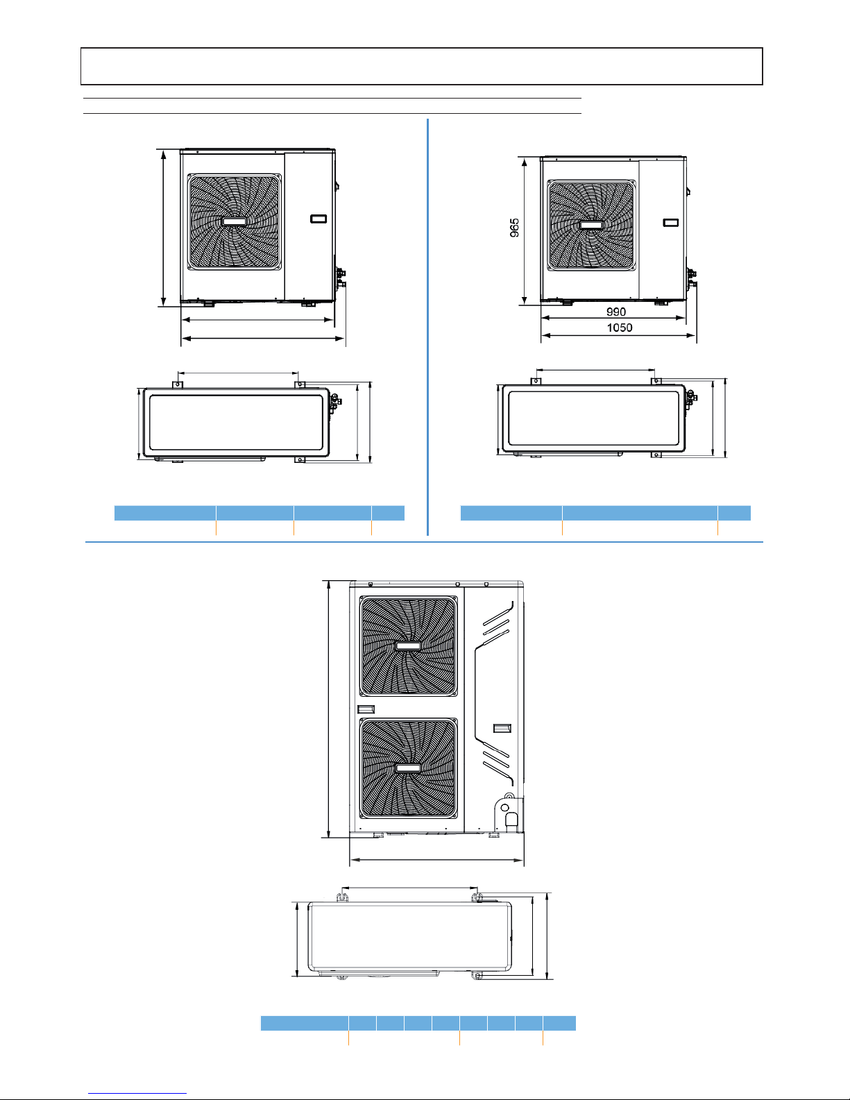
Overall diemnsions
Mod. 10 - 12 - 14 - 16 - 12T - 14T - 16T
Mod. 4 - 6
Mod. 8
860
333
350
355
895
960
590
1327
348
360
400
900
600
390
360
395
625
Models 10 12 14 16 12T 14T 16T
Weight net
99 115
kg
Models 4 6
Weight net
60 60
kg
Models 8
Weight net
76
kg
fi g. 1 fi g. 2
fi g. 3

11
INSTALLATION
Inspections on arrival
Al momento del ricevimento dell'unità è indispensabile controllare di aver ricevuto tutto il materiale indicato sul documento d'accompagnamento, ed inoltre che la stessa non abbia subito danni durante il trasporto. In caso affermativo, far costatare allo spedizioniere
l'entità del danno subito, avvertendo nel frattempo il nostro uffi cio gestione clienti. Soltanto agendo in questo modo e tempestiva-
mente sarà possibile avere il materiale mancante o il risarcimento dei danni.
Packing and storing
All machines are packed in cardboard boxes specific for each unit.
The indications required to correctly handle the appliance while storing and installing it are written
on the packing.
The storage temperature must be between -25°C and 55°C.
NOTA: Do not dispose of the packaging in the environment.
Do not dispose of, leave or leave within the reach of children the packaging material as it
may be a potential source of danger.
Once the place in which the unit is to be installed has been chosen (see the relative sections)
proceed as follows to unpack the two units.
The place of installation must be free of powders, fl ammable objects or mate-
rials or corrosive gases.
The unit is designed for wall hanging installation and is equipped as standard
with a hooking bracket. The fi xing to the wall must guarantee a stable and
effective support.
For the dismantling of the paneling and for normal maintenance
activities the minimum operating spaces must be respected.
Select an installation location where the following conditions are met:
- Place that allows to respect the maximum lengths allowed for pipes, connections to the unit of temperature probes, remote control etc ..
- Do not place objects or equipment on top of the unit.
- Make sure that all the precautions and prescriptions foreseen by local laws
and regulations regarding possible refrigerant leaks are correctly applied.
- It is advisable to place the boiler for domestic hot water production as close
as possible to the indoor unit.
Selecting the installation site and minimum operating area indoor unit
☞
☞
150
150
317
500 500
fi g. 1
fi g. 2
fi g. 3

12
INSTALLATION
Select an installation site where the following conditions are satisfi ed and one that meets with your customer's approval.
• Places that are well-ventilated.
• Places where the unit does not disturb next-door neighbors.
• Safe places which can bear the unit's weight and vibration and where the unit can be installed at an even level.
• Places where there is no possibility of fl ammable gas or product leak.
• The equipment is not intended for use in a potentially explosive atmosphere.
• Places where servicing space can be well ensured.
• Places where the units' piping and wiring lengths come within the allowable ranges.
• Places where water leaking from the unit cannot cause damage to the location (e.g. in case of a blocked drain pipe).
• Places where rain can be avoided as much as possible.
• Do not install the unit in places often used as a work space. In case of construction work (e.g. grinding etc.) where a lot of dust
is created, the unit must be covered.
• Do not place any objects or equipment on top of the unit (top plate)
• Do not climb, sit or stand on top of the unit.
• Be sure that suffi cient precautions are taken in case of refrigerant leakage according to relevant local laws and regulations.
Selecting the installation site and minimum operating area outdoor unit
Be sure to provide for adequate measures in order to prevent that the unit be used as a shelter by small animals. Small animals making
contact with electrical parts can cause malfunctions, smoke or fi re. Please instruct the customer to keep the area around the unit clean.
WARNING
>300
>300
>2000
>600
(Wall or obstacle)
Maintain
channel
Air outlet
Air inlet
A
ir inlet
air outlet
air inlet
wall / obstacle
Single installation
air inlet
Multiple installation in parallel between 2 or more units (front / back)
>2000 >500 >3000 >3000 >300
Multiple installation in parallel between 2 or more units (lateral)
>600
>2000
>300
Water Outlet
condensation drain
Mod. 4 - 6 - 8
Fix with bolt
>600mm
fasten with
bolts
fi g. 1
fi g. 2
fi g. 3
fi g. 4
fi g. 5
fi g. 6
Reserve water outlet
Reserve water outlet Water Outlet
(Need to knock open)
condensation drain
condensation drain reserve
(rubber stopper)
(semi-sheared)
(semi-sheared)
condensation drain reserve
input of power cables and refrigerant pipes
Mod. 10 - 12 - 12T - 14 - 14T - 16 - 16T

13
fi g. 7 fi g. 8
INSTALLATION
Installation diagrams
The indoor unit may be installed on top of the outdoor one and vice versa.
Outdoor unit positioned at the bottom and indoor unit at the top (fig. 1).
In this case a trap (6) must be made on the intake piping (3) to halt the downflow of
refrigerant and to avoid liquid returning to the compressor. The relative connection
pipes
must be insulated.
Key:
1. Outdoor unit
2. Indoor unit
3. Piping on gas side (larger diameter)
4. Piping on liquid side
5. Trap
Outdoor unit positioned at the top and indoor unit at the bottom (fig. 2).
In this case, traps (6) must be installed on the suction piping (3), every three meters
of difference in level. These traps will allow the oil to return to the compressor. The
relative connection pipes must be insulated.
Key:
1. Outdoor unit
2. Indoor unit
3. Piping on gas side (larger diameter)
4. Piping on liquid side
5. Trap
Note: The maximum difference in level between the indoor unit and outdoor
unit must not exceed the values given in the "LIMITS TO THE LENGTH AND
HEIGHT DIFFERENCE OF REFRIGERANT PIPES" section.
☞
fi g. 9
fi g. 10
Make sure there is enough room to do the installation
■ Prepare a water drainage channel around the foundation, to drain waste water from
around the unit.
■ If water does not easily drain from the unit, mount the unit on a foundation of concrete
blocks, etc. (the height of the foundation should be about 100 mm.
■ If you install the unit on a frame, please install a waterproof plate (about 100 mm) on the
underside of the unit to prevent water from coming in from the low side.
■ When installing the unit in a place frequently exposed to snow, pay special attention to
elevate the foundation as high as possible.
■ In heavy snowfall areas it is very important to select an installation site where the snow
will not affect the unit. If lateral snowfall is possible, make sure that the heat exchanger
coil is not affected by the snow (if necessary construct a lateral canopy).
■ As the outdoor temperature is measured via the outdoor unit air thermistor, make sure
to install the outdoor unit in the shade, or a canopy should be constracted to avoid direct sunlight, so that it is not influenced by the
sun’s heat, otherwise protection may be possible to the unit.
■ Check the strength and level of the installation ground so that the unit will not cause any operating vibration or noise after installation.
■ In accordance with the foundation drawing in the figure, fix the unit securely by means of the foundation bolts. (Prepare four sets
each of Ø10 Expansion bolts, nuts and washers which are readily available on the market.)
■ It is best to screw in the foundation bolts until their length is 20 mm from the foundation surface.
When installing the unit in a place exposed to strong wind, pay special attention to the following.
Set the outlet side at a right angle to the direction of the wind.
Strong winds of >5 m/s or more blowing against the unit's air outlet causes a short circuit (suction of discharge air), and this may
have the following consequences:
- Deterioration of the operational capacity.
- Frequent frost acceleration in heating operation.
- Disruption of operation due to rise of high pressure.
- When a strong wind blows continuously on the front of the unit, the fan can start rotating very fast until it breaks.

14
Cooling connections outdoor unit
Mod. 4 - 6 - 8
LIQUID
CONNECTION
GAS
CONNECTION
fi g. 1
Cooling connections indoor unit
Comply with the following indications when connecting the cooling pipes:
• Match the ends of the previously flared pipe with those of the connections on the indoor units or on the cocks of the outdoor units.
• Tighten the union by hand and then torque it with the aid of an adequate wrench (it is advisable to use a fox wedge to prevent
tensions from being created on the pipes).
INSTALLATION
Limits to the length and height difference of refrigerant pipes
The length of the refrigerant pipes between the indoor and outdoor units must be as short as possible and is in any case limited by
compliance with the maximum height difference values between the units.
Diminution of the difference in height between the units (H1,H2) and of the pipe lengths (L) will limit the load losses, consequently
increasing the overall efficiency of the machine.
Comply with the limits given in the following tables.
Contact our technical department for the required modifications if the units must operate beyond the specifications given
above.
MOD. OUTDOOR UNIT
4-6 8 10-12-14-16 12T-14T-16T
MOD. INDOOR UNIT
8 16 16T
Connections LIQUID line " 3/8
Connections GAS line " 5/8
Length with standard charge m 10
Cooling line maximum length m 20 30 50 50
Maximum diff.in height Outdoor unit low (H1) m 8 15 25 25
Maximum diff.in height Outdoor unit high (H2) m 10 20 30 30
Refrigerant charge
Type
R410A
Quantity of additional refrigerant per meter g/m 54

15
Front out pipe
Back out pipe
Side out pipe
Undersurface out pipe
Fat pipe
1
2
gas
liqulid
Mod. 10 - 12 - 12T - 14 - 14T - 16 - 16T
Front out pipe
Side out pipe
Back out pipe
Undersurface out pipe
Fat pipe
fi g. 2
LIQUID
CONNECTION
GAS
CONNECTION
fi g. 3
Refrigerant pipe insulation
To ensure system efficiency and its correct operation it is necessary to use pre-insulated
cooling connection lines easily available on the market. Pay also attention to the
connection points according to what described.
Use thermal insulating tape to tie the hoses, from the area connecting the outdoor unit
cocks to the upper end of the hose in correspondence of the wall entry point. (side
figure) .
Pipe fittings tightening
Make sure that the connecting zone is free from dust and dirt.
• Make sure that the flare and connection are perfectly aligned.
• Tighten the union first by hand and then with an adequate torque wrench.
Leaks could occur if the parts are insufficiently tightened, while the flare could be damaged if it is tightened too strongly.
The table below lists the torques recommended for the various pipe diameters
Nominal
Diameter
(“)
External
Diameter (mm) Ø
Tightening
torque
Nxm
3/8 9.52 30-40
5/8 15.88 60-65
INSTALLATION
16
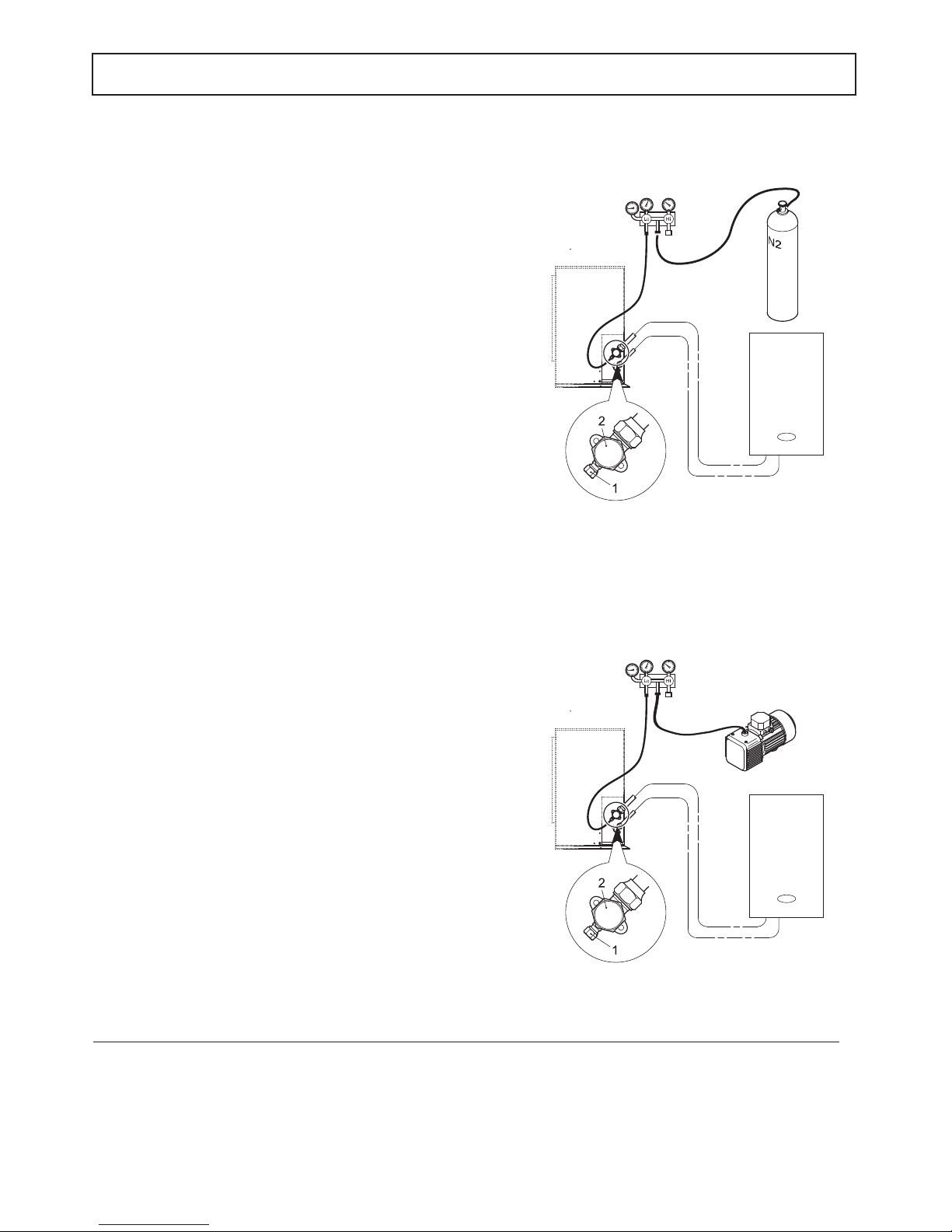
TIGHTNESS CHECK (RECOMMENDED OPERATION)
Before setting the system in a vacuum, it is advisable to make sure
that the cooling circuit is tight, including the connecting joints between
the pipes and the indoor unit. Proceed in the following way:
• With the service valves of the outdoor unit completely shut, remove
the cap from the service tap (1- side figure) of the gas connection
(the larger one)
• Connect the service valve to a monometric unit plus nitrogen bottle
(N2).
• Pressurize the system to a maximum 30 bar using the nitrogen in
the bottle.
• Use liquid soap to check that the joints are tight.
Keep the bottle vertical during the pressurizing operation to prevent
liquid nitrogen from infiltrating into the system!
• Check all the connection joints on both the outdoor and indoor
units to make sure that they are tight. Bubbles will form if leaks are
present. If bubbles appear, make sure that the unions have been
tightened and that the flares are the right shape.
• Wipe off the liquid soap with a rag.
• Reduce the pressure of the nitrogen in the circuit by loosening the
charge pipe from the bottle.
• Having reduced the pressure, disconnect the nitrogen bottle.
VACUUM OPERATION (OBLIGATORY)
Air and humidity in the cooling circuit impair the operation of the unit
with effects such as:
• Increased pressure.
• Reduced efficiency.
• Formation of ice on the capillary and subsequent blockage of the
same.
• Corrosion in the circuit.
This is why a vacuum must be created in the connection pipes and
indoor unit. Proceed in the following way:
• Connect the previously described charging pipe to the vacuum
pump.
• Turn on the relative knob on the monometric unit to allow the pump
to access the cooling circuit.
• Wait until the pressure level measured by the pressure gauge is
around 3 mm Hg (400 Pa)
• As soon as the required vacuum value is reached, shut the
connection cock and stop the vacuum pump.
fi g. 1
fi g. 2
■ To activate the system it is necessary to open both the liquid and gas shut-off valves of the outdoor unit: remove the caps from both
valves, and then open the valves with an Allen wrench.
■ It is advisable to open the valves when the installation of the system is complete from an electric and hydraulic point of view and it
is therefore possible to proceed with the fi rst start-up.
NOTA
☞
GAS
CONNECTIONS
U.I.
U.I.
U.E.
U.E.
GAS
CONNECTIONS
INSTALLATION

17
☞
The safety valve outlet must be connected to a funnel or collection pipe to prevent water spurting onto the fl oor in case of overpressure in the
heating circuit. Otherwise, if the discharge valve cuts in and fl oods the room, the boiler manufacturer cannot be held liable.
Before installation, fl ush all the pipes of the system thoroughly to remove any residuals or impurities that could affect proper operation of the
unit.
For that purpose only use suitable guaranteed products for heating systems (see next section), that do not harm metals, plastics or rubber.
The manufacturer declines any liability for damage caused to the generator by failure to properly clean the system.
AVVERTIMENTO
Tips for a successful installation
For a correct design and installation of the hydraulic plant comply the local laws governing safety matters and sound.
The following information is suggestion for a correct installation of the unit:
• Before connecting the unit to the system wash adequately the pipes using clean water, filling and emptying and cleaning the filters.
Only after that proceed connecting the unit to the system; this operation is crucial to ensure proper start-up without the need to have
repeated stops to clean the filter, with the possible risk of damage to heat exchangers and other components.
• Check by qualified personnel the quality of the water or of the mixture used; avoid the presence of inorganic salts, biological load
(seaweeds, etc.) suspended solids, dissolved oxygen and the pH. Water with inadequate characteristics can cause a pressure drop
increase due to a rapid fouling of the filter, energy efficiency decrease and corrosive symptom increase that can damage the unit.
• The pipes must have the least possible number of bends to minimize load losses and must be adequately supported in order to
prevent the connections of the unait from being excessively stressed.
• Install on-off valves near components that need to be serviced to isolate them when maintenance work needs to be done and to
allow them to be replaced without having to discharge the system.
• Before isolating the pipes and charging the system, carry out preliminary inspections to make sure that there are no leaks.
• Isolate all the chilled water pipes to prevent condensation from forming along the pipes themselves. Make sure that the material
used is the steam barrier type, failing this, cover the insulation with an appropriate protection. Also make sure that the air venting
valves can be accessed through the insulation.
• The circuit can be maintained under pressure using an expansion vessel (present in the unit) and a pressure reducer. A system filling
device can be used that automatically, under a pressure value, provides for the loading and maintenance of the desired pressure.
• Check that all plant components are able to withstand the maximum static pressure (depending on the height of the building to be
served).
Water component for corrosion limit
Water filter
pH 7.5 ÷ 9.0 SO4 -- < 100 ppm
HCO3 -/ SO4 -- >1.0
Total hardness 8.0 ÷ 15.2 °F
Cl- < 50 ppm
PO4 3- < 2.0 ppm
NH3 < 0.5 ppm
Free Chlorine < 0.5 ppm
Fe3+ < 0.5 ppm
Mn++ < 0.05 ppm
CO2 < 50 ppm
H2S < 50 ppb
Temperature < 65 °C
Oxygen content < 0.1 ppm
To avoid corrosion problems in water exchangers make sure that the water used in the plant meets the requirements listed in the table.
It is mandatory to install at the inlet of the unit the Y-shape water filter (supplied with the unit).
Water pipework
Requirements
For temperature probes (eg T5 or T1b) the maximum permitted cable length is 20m. This is the maximum allowed distance between the domestic
hot water tank and the unit (only for installations with a domestic hot water tank). To optimize efficiency, we recommend installing the domestic hot
water tank as close as possible to the unit
■ If the installation is equipped with a domestic hot water tank (optional), please refer to the domestic hot water tank Installation &
Owner's Manual.
■ If there is no glycol in the system (antifreeze) or if the unit is not able to remain electrically powered for possible blackouts, in order
to avoid possible icing problems, empty the water during winter.
NOTE
INSTALLATION

18
INSTALLATION
■ Be careful not to deform the unit’s piping by using excessive force when connecting the piping. Deforming the piping
can cause the unit to malfunction.
■ The unit is only to be used in a closed water system. Application in an open water circuit can lead to excessive corrosion of the
water piping.
■ Water connections must be made in accordance with the outlook diagram delivered with the unit, with respect to the water intake
and water outlet (refer to section "DIMENSIONAL AND PHYSICAL DATA").
If air, moisture or dust gets in the water circuit, problems may occur. Therefore, always take into account the following when connecting
the water circuit:
■ Use clean pipes only.
■ Hold the pipe end downwards when removing burrs
■ Cover the pipe end when inserting it through a wall so that no dust and dirt enter.
■ Use a good thread sealant for sealing the connections. The sealing must be able to withstand the pressures and temperatures of
the system.
■ When using non-brass metallic piping,make sure to insulate both materials from each other to prevent galvanic corrosion. Never
use Zn-coated parts in the water circuit. Excessive corrosion of these parts may occur as copper piping is used in the unit's internal
water circuit.
Correction factor for the use of glycol in heating mode
ETHYLENE GLYCOL with water produced between 30 ÷ 55 º C.
PROPYLENE GLYCOL with water produced between 30 ÷ 55ºC.
Percentage Of glycol in mass / volume 0 / 0 10 / 8,9 20 / 18,1 30 / 27,7 40 / 37,5
Freezing point [°C] 0 -3,2 -8 -14 -22
CCPT - Heating capacity 1,000 0,995 0,985 0,975 0,970
CCPA - Power input 1,000 1,010 1,015 1,020 1,030
CCQA - Water flow rate 1,000 1,038 1,062 1,091 1,127
CCDP - Water pressure drop 1,000 1,026 1,051 1,077 1,103
Percentage Of glycol in mass / volume 0 / 0 10 / 9,6 20 / 19,4 30 / 29,4 40 / 39,6
Freezing point [°C] 0 -3,3 -7 -13 -21
CCPT - Heating capacity 1,000 0,990 0,975 0,965 0,955
CCPA - Power input 1,000 1,010 1,020 1,030 1,040
CCQA - Water flow rate 1,000 1,018 1,032 1,053 1,082
CCDP - Water pressure drop 1,000 1,026 1,051 1,077 1,103
Correction factor for the use of glycol in cooling mode
ETHYLENE GLYCOL with water produced between 5 ÷ 20 º C.
PROPYLENE GLYCOL with water produced between 5 ÷ 20 º C.
Percentage Of glycol in mass / volume 0 / 0 10 / 8,9 20 / 18,1 30 / 27,7 40 / 37,5
Freezing point [°C] 0 -3,2 -8 -14 -22
CCPF - Cooling capacity 1,00 0,99 0,98 0,97 0,95
CCPA - Power input 1,00 1,00 0,99 0,99 0,98
CCQA - Water flow rate 1,00 1,04 1,08 1,12 1,16
CCDP - Water pressure drop 1,00 1,08 1,16 1,25 1,35
Percentage Of glycol in mass / volume 0 / 0 10 / 9,6 20 / 19,4 30 / 29,4 40 / 39,6
Freezing point [°C] 0 -3,3 -7 -13 -21
CCPF - Cooling capacity 1,00 0,98 0,96 0,94 0,92
CCPA - Power input 1,00 0,99 0,98 0,95 0,93
CCQA - Water flow rate 1,00 1,01 1,03 1,06 1,09
CCDP - Water pressure drop 1,00 1,05 1,11 1,22 1,38
Protecting the water circuit against freezing
Frost can cause damage to the hydraulic circuit. If the unit's hydraulic circuit is expected to be subject to temperatures that may cause
freezing, care must be taken to prevent freezing of the system.
All hydraulic parts are insulated to reduce heat loss. Insulation must be present on the fi eld piping.
The unit is already equipped with several features to prevent freezing.
■ The software contains special functions using the heat pump to protect the entire system against freezing.
When the temperature of the water fl ow in the system drops to a certain value, the software will heat the water, either using the heat
pump, the electric heating tap, or the backup heater(if backup heater box is installed). The freeze protection function will turn off only when
the temperature increases to a certain value.
In case of a power failure, the features mentioned above cannot protect the unit from freezing. Since a power failure could happen when the
unit is unattended, the supplier recommends adding glycol to the water system. Refer to “Caution: Use of glycol”.
Since a power failure could happen when the unit is unattended, the supplier recommends adding glycol to the water system. Refer to
“Caution: Use of glycol”.
Depending on the expected lowest outdoor temperature, make sure the water system is fi lled with a concentration of glycol as mentioned
in the table below.
When glycol is added to the system, the performance of the unit will be affected. The correction factor of the unit capacity, fl ow rate and
pressure drop of the system is listed in the table below:

19
INSTALLATION
ETHYLENE GLYCOL IS TOXIC
Use of glycol
■ Glycol use for installations with a domestic hot water tank:
- Only propylene glycol having a toxicity rating or class of 1, as listed in "Clinical Toxicology of Commercial Products, 5th edition" may be used.
■ If there is too much pressure when using glycol, connect the safety valve to a drain pan to recover the glycol.
■ Uninhibited glycol will turn acidic under the infl uence of oxygen. This process is accelerated by presence of copper and at
higher temperatures. The acidic uninhibited glycol attacks metal surfaces and forms galvanic corrosion cells that cause severe
damage to the system.
It is of extreme importance:
■ That the water treatment is correctly executed by a qualifi ed water specialist.
■ That a glycol with corrosion inhibitors is selected to counteract acids formed by the oxidation of glycols.
■ That in case of an installation with a domestic hot water tank, only the use of propylene glycol is allowed. In other installations
the use of ethylene glycol is fi ne.
■ That no automotive glycol is used because their corrosion inhibitors have a limited lifetime and contain silicates that can foul
or plug the system;
■ That galvanized piping is not used in glycol systems since it may lead to the precipitation of certain elements in the glycol’s
corrosion inhibitor;
■ To ensure that the glycol is compatible with the materials used in the system.
■ Be aware of the hygroscopic property of glycol. It absorbs moisture from the environment.
■ Leaving the cap off the glycol container causes the concentration of water to increase. The glycol concentration is then lower
and the water could freeze.
■ Preventive actions must be taken to ensure minimal exposure of the glycol to air.
WARNING
CAUTION
During fi lling, it might not be possible to remove all air in the system. Remaining air will be removed through the automatic air
purge valves during the fi rst operating hours of the system. Topping up the water afterwards might be required.
■ The water pressure indicated on the manometer will vary depending on the water temperature (higher pressure at
higher water temperature). However, at all times water pressure should remain above 0.3 bar to avoid air entering the circuit.
1. Connect the water supply to the fi ll valve and open the valve.
2. Make sure the automatic air purge valve is open (at least 2 turns).
3. Fill with water until the manometer indicates a pressure of approximately 2.0 bar. Remove air in the circuit as much as possi-
ble using the air purge valves. Air present in the water circuit might cause malfunctioning of the backup heater.
NOTE
Filling with water
Piping insulation
The complete hydraulic circuit that includes all the pipes must be insulated to avoid heat loss, condensation during operation,
reduction of heating or cooling capacity, as well as to prevent freezing of water pipes during winter.
☞

20
INSTALLATION
■ Wiring must be carried out in accordance with the wiring diagram supplied with the unit and the instructions given in this paragraph.
■ All wiring and electrical components must be installed by a qualifi ed electrician.
■ Provide a main switch or other disconnection devices in the system in accordance with local laws and regulations.
■ Use a dedicated power line.
■ Install fuses (or circuit breakers) and power cables that match the maximum electrical current of the unit.
■ Install a differential switch according to local laws and regulations. Failure to install a differential switch can result in electric shock
and fi re.
■ Install a differential switch with the following characteristics:
- intervention value equal to 30 mA
- trip time less than 0.1 s
■ Make sure all electrical connections are carried out properly. Use the specifi ed cables and ensure that the terminal connections
and cables are protected from water and other external forces to avoid the risk of fi re.
■ Accommodate the power supply and control cables so that the front panel can be mounted correctly and therefore do not force the
cables themselves to avoid the risk of fi re or electric shock.
■ Do not compress the cables and make sure that they do not come into contact with the pipes and sharp edges. Ensure that no
external pressure is applied to the cables.
BEFORE ANY OPERATION WHICH REQUIRES REMOVING THE COVER, DISCONNECT THE UNIT FROM THE POWER SUPPLY THROUGH THE MAIN SWITCH.
DO NOT TOUCH THE ELECTRICAL COMPONENTS IN ANY CASE WITH THE CLOSED MAIN SWITCH! THERE IS THE
RISK OF ELECTRIC SHOCK WITH RISK OF INJURY OR DEATH!
The appliance must be connected to an effective earthing system, as provided for by the current safety regulations. Have
the effi ciency and suitability of the earthing system checked by professionally qualifi ed personnel, the manufacturer is not
responsible for any damage caused by lack of earthing of the system.
CAUTION
Electrical conections indoor unit
1. Opening the front panel
Some components inside the boiler can reach high temperatures that
could cause serious problems burns. Before carrying out any operation,
wait for these components to cool or alternatively wear suitable gloves.
To dismount the front panel of the indoor unit:
- Partially unscrew the screws A (see figure to the side).
- Pull the panel B out and release it from the upper fixings.
2. Make the connections referring to the functional electrical diagram
present in this manual.
3. Proceed in reverse order to reassemble the front panel. Make sure
that it is correctly attached to the upper fixing and completely resting on
the side panels. The head of the screw "A", once tightened, must not be
underneath the lower bending stop (see figure at the side).
OK NO
A
A
A
B
fi g. 1
21
INSTALLATION
■ The unit is equipped with an inverter. Installing a power factor correction not only reduces the effect of power factor improvement, but can also cause an abnormal heating of the condenser due to high frequency waves. Never install a power
factor device as it may cause damage to the unit.
☞
■ A main switch or other means of disconnection, having a contact separation in all poles, must be incorporated in the fi xed wiring in
accordance with relevant local laws and regulations.
■ Switch off the power supply before making any connections.
■ Never squeeze bundled cables and make sure they do not come in contact with the piping and sharp edges. Make sure no exter-
nal pressure is applied to the terminal connections.
■ All fi eld wiring and components must be installed by a licensed electrician and must comply with relevant local laws and regulations.
■ The fi eld wiring must be carried out in accordance with the wiring diagram supplied with the unit and the instructions
given below.
■ Be sure to use a dedicated power supply. Never use a power supply shared by another appliance.
■ Be sure to establish a ground. Do not ground the unit to a utility pipe, surge protector, or telephone ground.
Incomplete grounding may cause electrical shock.
■ Be sure to install a ground fault circuit interrupter (30 mA). Failure to do so may cause electrical shock.
■ Be sure to install the required fuses or circuit breakers.
WARNING
■ Be sure to install a differential switch with the following characteristics:
- intervention value equal to 30 mA
- trip time less than 0.1 s
- that it is compatible with the inverter (resistant to high frequency electromagnetic disturbances) in order to avoid unnecessary
interventions
NOTA
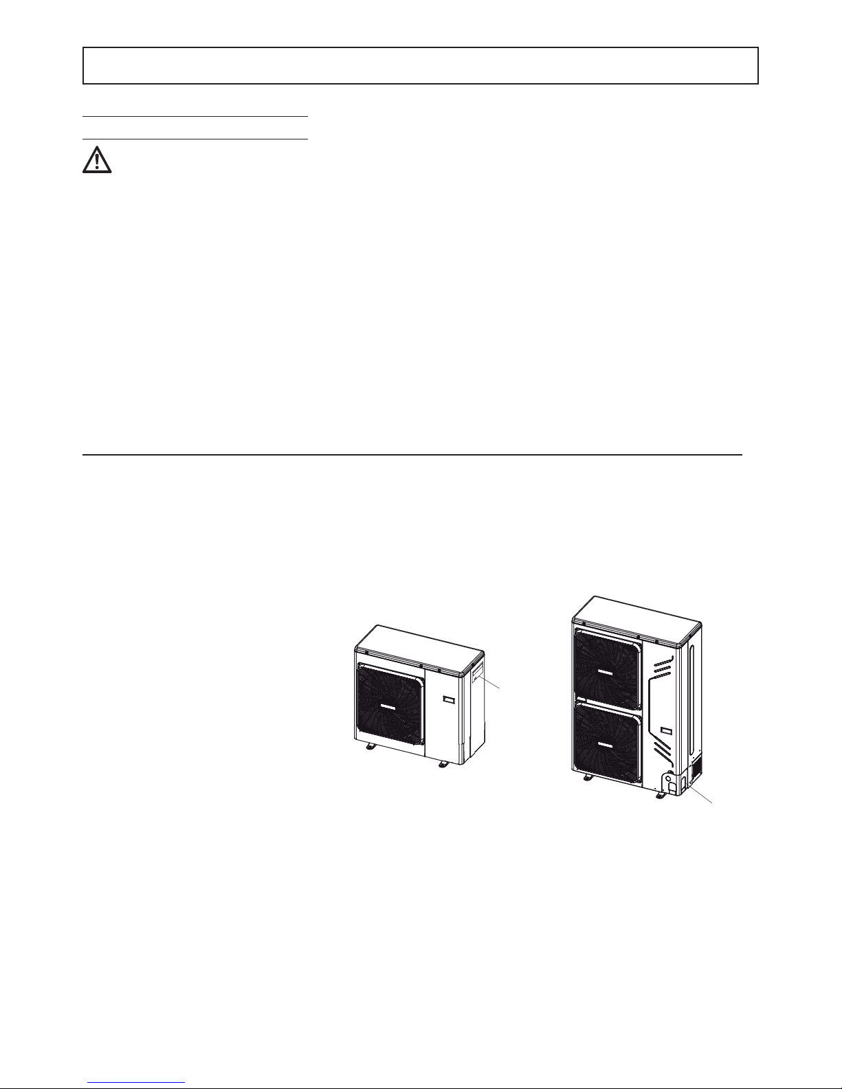
Electrical conections outdoor unit
1. Remove the side panel (1).
2. Make the connections referring to the
wiring diagrams of the unit.
3. Close the machine up again.
1
1
Mod. 10 - 12 - 14 - 16 - 12T - 14T -16T
Mod. 4 - 6 - 8
☞
fi g. 1
fi g. 2

22
INSTALLATION
Power supply connection
Electrical connections
Procedure
1. Connect the cables to the appropriate terminals as shown on the diagram.
2. Fix the cables with cable ties.
Recommended cable H05RN-F or as installed. See specifi c legislation. The customer must install the automatic circuit
breaker.
Outdoor unit MOD.
4 6 8 10 12 14 16 12T 14T 16T
Power input " 220-240V 50 Hz
380-415V 3+N+PE
50Hz
Automatic circuit breaker A 16 20 32 16
Power supply cross-section of cable mm
2
3x2,5 3x4,0 3x4,0 5x2,5
Cavo di comunicazione
tra unità interna ed esterna
MOD.
4 6 8 10 12 14 16 12T 14T 16T
Wiring size (shielded cable)
mm
2
3x0,75
Indoor unit without booster MOD.
816
Power input " 220-240V 50 Hz
Automatic circuit breaker A 2
Power supply cross-section of cable mm
2
3x1,0
Indoor unit with booster MOD.
81616T
Power input " 220-240V 50 Hz
380-415V 3+N+PE
50Hz
Automatic circuit breaker A 16 16 10
Power supply cross-section of cable mm
2
3x2,5 3x2,5 5x2,5
Indoor Unit
Outdoor Unit
Power Supply
3-shield wire
COMANDO
REMOTO
ABXYE
ABXYE
P Q E T5 T5 T1b T1b
IBH1 IBH2 PE TH N C H A1 A2 N N N PE
IBH1 IBH2
LPEPEN
TH PE TBH L1
AHS1 AHS2
P_o PEPE P_d SV2
Power Supply
LN
EQP
Mod. 4 - 6 - 8 - 10 - 12 - 14 - 16
NOTA
Connect the communication cable between indoor unit and outdoor unit keeping the correspondence of the letters
indicated on the terminals (P with P, Q with Q, E with E).
Connect the communication cable between indoor unit and remote control keeping the correspondence of the let-
ters indicated on the terminals (A with A, B with B....).
OUTDOOR UNIT
REMOTE
CONTROL
power supplie
power supplie
comunication
(shielded cable)
INDOOR UNIT
☞
fi g. 1
 Loading...