

Ferroli NEW CONDENS FS 600 SERIES, 605, 606, 604, 607 Instructions For Use, Installation And Maintenance
...Page 1

NEW CONDENS FS 600 SERIES
Cast Aluminium Floor Standing Condensing Boilers for Natural Gas
Rev.00/12-2015-PB/IB600
INSTRUCTIONS FOR USE, INSTALLATION AND MAINTENANCE
Page 2

NEW CONDENS FS 600 SERIES
EN
Declaration of conformity
:
Gas Appliance Directive 2009/142
Efficiency Directive 92/42
Low Voltage Directive 2006/95
Electromagnetic Compatibility Directive 2004/108
1015
President and Legal Representative
2
Page 3

NEW CONDENS FS 600 SERIES
Manufacturer's liability
Our products are manufactured in compliance with the requirements of the various directives applicable. They are therefore de-
livered with the marking and any documents necessary. In the interests of the quality of our products, we strive constantly to im-
prove them. We therefore reserve the right to modify the specifications given in this document.
Our liability as manufacturer may not be invoked in the following cases:
Failure to abide by the instrucons on installing the appliance.
Failure to abide by the instrucons on using the appliance.
Faulty or insucient maintenance of the appliance.
Installer's liability
The installer is responsible for the installation and initial commissioning of the appliance. The installer must abide by the following
instructions:
Read and follow the instructions given in the manuals provided with the appliance.
Install the appliance in compliance with prevailing legislation and standards.
Carry out initial commissioning and any checks necessary. Explain the installation to the user.
If maintenance is necessary, warn the user of the obligation to check the appliance and keep it in good working order.
Give all the instruction manuals to the user.
User's liability
To guarantee optimum running of the installation, you must abide by the following instructions:
Read and follow the instructions given in the manuals provided with the appliance.
Call on a qualified professional to carry out installation and initial commissioning.
Get your installer to explain your installation to you.
Have the required checks and services done by a qualified professional.
Keep the instruction manuals in good condition close to the appliance.
3
Page 4
1. GENERAL
Carefully read and follow the instructions contained in
this instruction booklet.
After boiler installation, inform the user regarding its
operation and give him this manual, which is an integral and essential part of the product and must be kept
with care for future reference.
Installation and maintenance must be carried out by pro-
fessionally qualified personnel, in compliance with the
current regulations and according to the manufacturer's
instructions. Do not carry out any operation on the
sealed control parts.
Incorrect installation or inadequate maintenance can
result in damage or injury. The manufacturer declines
any liability for damage due to errors in installation and
use, or failure to follow the instructions.
Before carrying out any cleaning or maintenance opera-
tion, disconnect the unit from the electrical power supply using the switch and/or the special cut-off devices.
In case of a fault and/or poor operation, deactivate the
unit and do not try to repair it or directly intervene.
Contact professionally qualified personnel. Any repair/
replacement of the products must only be carried out by
qualified personnel using original replacement parts.
Failure to comply with the above could affect the safety
of the unit.
This unit must only be used for its intended purpose.
Any other use is deemed improper and therefore
hazardous.
The packing materials are potentially hazardous and
must not be left within the reach of children.
The unit must not be used by people (including children)
with limited physical, sensory or mental abilities or without experience and knowledge of it, unless instructed or
supervised in its use by someone responsible for their
safety.
The unit and its accessories must be appropriately dis-
posed of, in compliance with the current regulations.
The images given in this manual are a simplified repre-
sentation of the product. In this representation there
may be slight and insignificant differences with respect
to the product supplied.
Introduction
Dear Customer,
HEALTH & SAFETY
The electricity at work regulations, 1989.
The manufacturer's notes must NOT be taken, in any
way, as overriding statutory obligaons.
IMPORTANT. These appliances are CE cerfied for
safety and performance. It is, therefore, important
that no external control devices, e.g. flue dampers,
economisers etc., are directly connected to these
appliances unless covered by these Installaon and
servicing Instrucons or as otherwise recommended
by Ferroli Ltd in wring. If in doubt please enquire.
Any direct connecon of a control device not
approved by Ferroli Ltd could invalidate the
cerficaon and the normal appliance warranty. It
could also infringe the Gas Safety Regulaons and
the above regulaons.
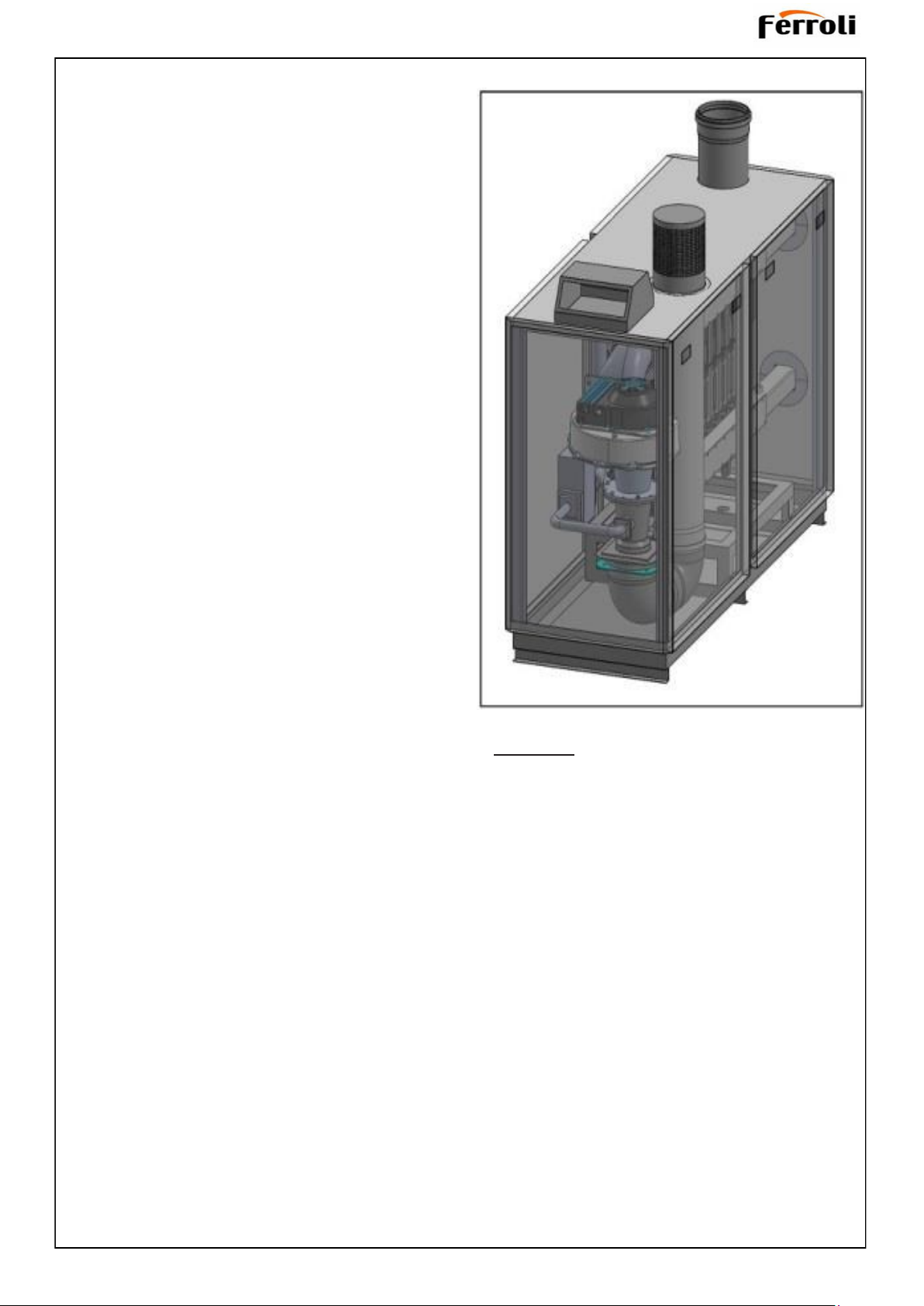
Thank you for choosing the New Condens FS Series, a
floor-standing boiler featuring advanced design, cutting-
edge technology, high reliability and quality construc-
tion. Please read this manual carefully since it provides
important information on safe installation, use and mainte-
nance. New Condens FS Series is a high efficiency,
low emissions premix condensing heat generator for
heating, running on natural gas and equipped with a micro-
processor control system.
The boiler body consists of a sectional cast Al-Si-Mg
alloy heat exchanger and a woven mesh premix burner
in stainless steel, equipped with electronic ignition with
ionisation flame control, modulating speed fan and mod-
ulating gas valve. New Condens FS Series is a heat
generator arranged to operate alone or in cascade.
4
Page 5
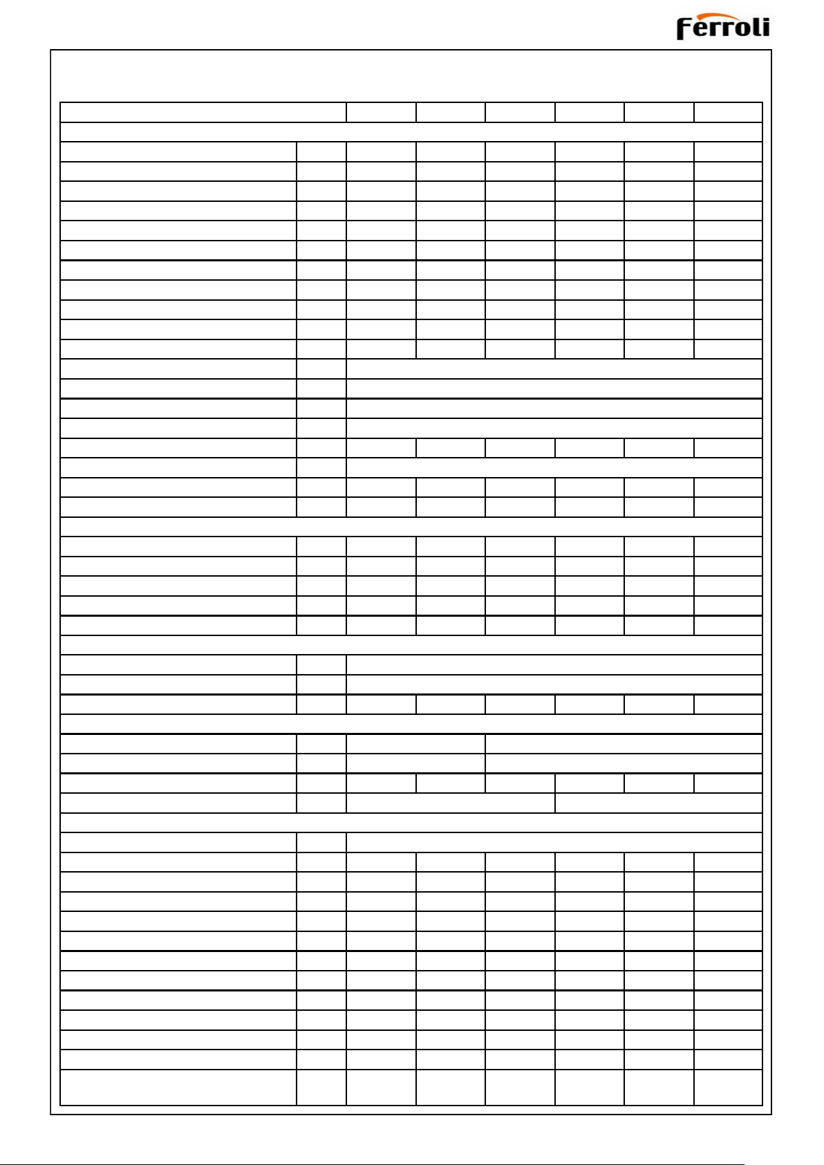
Technical Data Table
FERROLI NEW CONDENS 600 SERIES 604 605 606 607 608 609
EFFİCİENCY AND PERFORMANCE
Max. heat input in CH mode kW 198 266 331 407 475 542
Min. heat input in CH mode kW 30 37 45 55 63 74
Max. heat output in CH mode (80/60°C) kW 184 258 321 390 456 522
Min. heat output in CH mode (80/60°C) kW 28 36 44 53 60 72
Max. heat output in CH mode (50/30°C) kW 200 269 339 408 477 542
Min. heat output in CH mode (50/30°C) kW 32 40 49 58 68 79
Efficiency at Pmax (80/60°C) % 95.2 96.9 96.9 95.8 96.0 96.4
Efficiency at Pmin (80/60°C) % 95.0 97.2 97.7 96.3 95.2 96.8
Efficiency at Pmax (50/30°C) % 100.3 101.1 102.4 100.2 100.4 100.4
Efficiency at Pmin (50/30°C) % 105.5 108.1 108.9 105.4 107.9 106.8
Efficiency at 30% (30°C) % 105.7 107.6 103.3 105.3 107.1 106.7
NOx class 5
Max. central heating temperature °C 80
Max. domestic hot water temperature °C 65
Max. heat exchanger ΔT °C 26
Max. stack pressure at Pmax Pa 190 200 230 180 220 250
Operating pressure (min – max) bar 0.8 - 6
Water resistance at ΔT°C 11 mbar 210 200 210 230 220 250
Water resistance at ΔT°C 20 mbar 80 90 91 100 93 110
STRUCTURAL CHARACTERİSTİCS
Water Contents l 18.6 22.9 26.4 32.6 36.9 41.0
Empty weight kg 195 237 305 358 380 423
Width mm 600 600 660 710 710 710
Height mm 1500 1500 1500 1500 1500 1500
Depth mm 1320 1400 1590 1800 1900 1990
ELECTRİCAL SPECİFİCATİONS
Power supply voltage V/Hz 230 / 50
Protection level IP 20
Power consumption W 320 390 460 550 700 850
WATER AND GAS FİTTİNGS
Central heating flow outlet 2” DN 65
Central heating return inlet 2” DN 65
Gas inlet 1 ¼” 1 ½” 1 ½” 2” 2” 2”
Flue gas outlet (Ø) mm 160 200
COMBUSTİON
Type of appliance B23, C63
Combustion efficiency at Pmax % 98.2 98.2 98.3 98.2 98.1 98.2
Combustion efficiency at Pmin % 98.4 98.4 98.5 98.4 98.4 98.4
Flue gas temperature at Pmax (80/60°C) °C 80.2 80.5 79.6 80.5 79.3 80.2
Flue gas temperature at Pmin (80/60°C) °C 66.7 63.8 63.1 65.2 64.7 63.5
Flue gas temperature at Pmax (50/30°C) °C 55.5 56.8 54.7 54.6 55.7 56.8
Flue gas temperature at Pmin (50/30°C) °C 33.9 34.5 33.8 35.6 34.6 34.5
Flue gas flow-rate at Pmax g/s 92 118 145 171 198 224
Flue gas flow-rate at Pmin g/s 34 42 52 60 68 73
CO2 at Pmax % 9.0 9.1 9.1 9.3 9.2 9.3
CO2 at Pmin % 8.3 8.1 8.2 8.3 8.2 8.5
CO O2=0% weighted ppm 44 51 45 55 53 52
NOx O2=0% weighted
mg/
kWh
31 30 28 29 31 30
5
Page 6
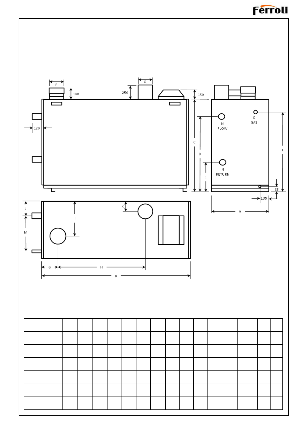
Boiler Dimensions
MODEL A B C D E F G H I K L M N O P Q
604 604 1200 1270 1046 450 1040 178 591 294 110 127 305 R 2” R 1 ¼” 160
605 604 1285 1270 1058 475 1056 178 675 299 110 127 305 R 2” R 1 ½” 160
606 660 1470 1270 1078 505 1090 169 793 338 120 150 305 DN65 R 1 ½” 160
607 714 1681 1270 1078 505 1150 195 904 415 192 225 225 DN65 R 2” 200
608 714 1776 1270 1078 505 1150 195 999 415 192 225 225 DN65 R 2” 200
609 714 1871 1270 1078 505 1150 178 1089 415 192 225 225 DN65 R 2” 200
100
100
120
180
180
180
6
Page 7
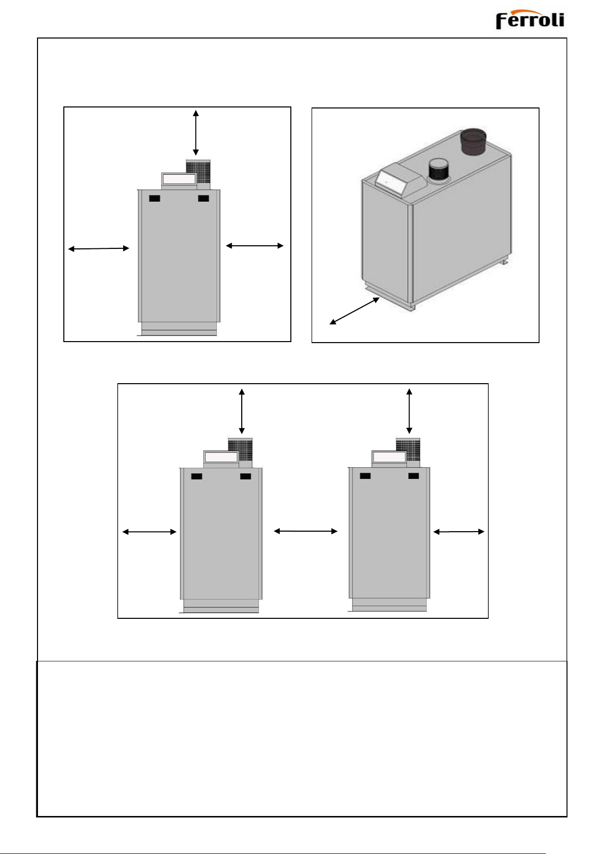
Recommended Minimum Distances
800 mm
800 mm
800 mm
800 mm
800 mm
200 mm
600mm
800 mm
800 mm
BOILER CLEARANCES
The minimum dimensions as indicated must be respected to
ensure good access around the boiler.
Recommended minimum clearances are as follows.
Front: 600mm; except, access doors may be closer,
but not less than 200mm and 600mm must still be
available for service across the width of the boiler.
Rear: 1000mm or adequate space from the rear of the
jacket to make the flue connections and access to the
flue sample point, drain connection, flue and any safety
or control devices.
Top: 800mm.
Left side: 800mm
Right side: 800mm
Between boilers: 200mm
7
Page 8

Detailed recommendations are contained in the following Standards and Codes of Practice:
BS EN 1212:2005 Chemicals used for treatment of water intended for human consumption. Sodium polyphosphate
BS EN 13076:2003 Devices to prevent pollution by backflow of potable water. Unrestricted air gap. Family A. Type A
Devices to prevent pollution by backflow of potable water. Air gap with non-circular overflow
BS EN 13077:2008
BS EN 13959:2004 Anti-pollution check valves. DN 6 to DN 250 inclusive Family E, type A, B, C, and D
BS EN 1567:1999
BS 6880-2:1988
BS 6644:2011
(unrestricted). Family A. Type B
Building valves. Water pressure reducing valves and combination water reducing valves. Requirements and tests.
Code of practice for low temperature hot water heating systems of output greater than 45 kW. Selection of equipment
Specification for the installation and maintenance of gas-fired hot water boilers of rated inputs between 70 kW (net) and 1.8 MW (net) (2nd and 3rd family gases)
BS 5854:1980 Code of practice for flues and flue structures in buildings
Code of practice for low temperature hot water heating systems of output greater than 45 kW. Funda-
BS 6880-1:1988
BS 6880-2:1988 Selection of equipment
BS 6880-3:1988 Installation, commissioning and maintenance
BS EN 13384-1:2015 Chimneys. Thermal and fluid dynamic calculation methods. Chimneys serving one heating appliance
BS EN 13384-2:2015
PD CEN/TR 1749:2014
BS 2879:1980 Specification for draining taps (screw-down pattern)
BS 7671:2008+A3:2015 Requirements for Electrical Installations. IET Wiring Regulations
mental and design considerations
Chimneys. Thermal and fluid dynamic calculation methods. Chimneys serving more than one heating
appliance
European scheme for the classification of gas appliances according to the method of evacuation of
the combustion products (types)
IGE/UP/1 Soundness testing and purging of industrial and commercial gas installations
IGE/UP/2 Gas installation pipework, boosters and compressors on industrial and commercial premises
IGE/UP/10 Installation of gas appliances in industrial and commercial premises
8
Page 9

INTRODUCTION
The New Condens FS Series boilers are fully automatically
controlled, floor standing, fanned, super efficient condensing
appliances.
The Siemens LMS14 Boiler Management Unit (BMU) built
into the appliance is a comprehensive boiler control unit
which provides all supervisory and control functions required for burner operation, space heating and DHW heating. It also offers modular system extensions in the form of
integrated communication interfaces.
Through a sophisticated control system combined with premix burner technology and an aluminium heat exchanger,
the boilers are capable of high operating efficiencies of
98.1% (gross) and low emissions.
The boilers can draw their combustion air from the room or
via ducting from outside.
These boilers are certified to meet the requirements of the
EC
Gas Appliance Directive, Boiler Efficiency Directive, EMC,
Low Voltage Directive and 2009/125/EC Ecodesign Directive.
SAFETY
Current Gas Safety (Installation and Use) Regulations or rules
in force
The appliance is suitable only for installation in GB and IE and
should be installed in accordance with the rules in force.
In GB, the installation must be carried out by a Gas Safe Registered Engineer or in IE by a competent person. It must be
carried out in accordance with the relevant requirements of
the:
Gas Safety (Installation and Use) Regulations
The appropriate Building Regulations either The Building Regulations, The Building Regulations (Scotland), Building Regulations (Northern Ireland).
The Water Fittings Regulations or Water byelaws in Scotland.
FOUNDATION / LOCATION OF BOILER
The boiler must stand on a floor which must be flat, level
and of a suitable load bearing capacity to support the
weight of the boiler (when filled with water) and any
ancillary equipment.
Ideally the boiler should be placed on a plinth exceeding
the plan area of the boiler by 75mm on each side and at
least 100mm high.
The boiler must not be fitted outside.
GAS SUPPLY
The local gas supplier should be consulted, at the installation planning stage, in order to establish the availability of
an adequate supply of gas. An existing service pipe must
NOT be used without prior consultation with the local gas
supplier.
A gas meter can only be connected by the local gas
supplier or by a Gas Safe Registered Engineer or in IE by a
competent person.
An existing meter should be checked, preferably by the gas
supplier, to ensure that the meter is adequate to deal with
the rate of gas supply required. A minimum working gas
pressure of 20mbar MUST be available at the boiler Inlet
for Natural gas.
Do not use pipes of smaller size than the boiler inlet gas
connection.
The complete installation MUST be tested for gas
soundness and purged in accordance with the appropriate
standards.
Gas Boosters
A gas booster is required if the gas pressure
available at the boiler is lower than that required by
the boiler manufacturer to attain the flow rate for
maximum burner input rating.
Location of the booster requires careful consideration but
should preferably be closer to the burner rather than the
gas meter. Ventilation should also be considered to ensure
ambient temperature do not exceed designed
recommendations.
Further guidance is provided in IGE/UP/2.
The Current I.E.E. Wiring Regulations.
Where no specific instructions are given, reference should be
made to the relevant British Standard Code of Practice.
In IE, the installation must be carried out by a Competent Person and installed in accordance with the current Building Reg-
ulations and reference should be made to the current ETCI
rules for electrical installaon.
The boilers have been tested and conform to EN 15502-1 for
use with Natural Gas
SAFE HANDLING OF SUBSTANCES
No asbestos, mercury or CFCs are included in any part of the
boiler or its manufacture.
FROST PROTECTION
The boiler has built into its control system the facility to protect
the boiler only against freezing.
The set point for the boilers frost protection can be set via the
Siemens LMS Controller
Frost protection is ensured, independent of heat requests or
connected plant components. Therefore, boiler control checks
frost protection autonomously and causes the burner to be
started, if necessary.
Frost protection for the boiler is activated whenever the boiler
temperature drops below the frost protection set point.
9
Page 10

FLUE INSTALLATION
IMPORTANT. It is the responsibility of the installer to
ensure, in practice, that products of combustion discharging from the terminal cannot re-enter the building
or any other adjacent building through ventilators, windows, doors, other sources of natural air infiltration, or
forced ventilation / air conditioning.
If this should occur the appliance MUST be isolated from
the gas supply and labelled as 'unsafe' until corrective
action can be taken.
Terminal Position
Due to the high efficiency of the boilers pluming will occur.
Particular care should be taken in the case of large output
boiler installations in complying with the requirements of the
Clean Air Act.
The flue must be installed in accordance with the appropriate Building Regulations and standards listed on page
8 and in compliance with BS6644. In IE refer to
I.S.820:2000.
Boiler Type (PD CEN/TR 1749:2014)
C63 = A room sealed appliance intended to be
connected to a separately approved and
marketed system for the supply of combustion
air and discharge of combustion products.
The fan is up stream of the combustion
chamber.
B23 = An appliance intended to be connected
to a flue which evacuates the products
of combustion to the outside of the room
containing the boiler. The combustion air is
drawn directly from the room. The fan is up
stream of the combustion chamber.
IMPORTANT NOTE.
If combustion air is drawn from within the boiler room,
ensure no dust or airborne debris can be ingested into
the appliance. Dusty concrete flooring should be
sealed to reduce the presence of dust. Ideally where
possible duct the air supply into the boiler room from a
clean source outside the boiler room / building.
Where it is not possible to duct air from outside the
boiler, the air inlet guard MUST be used,
FLUE SYSTEM DESIGN
Due to the high efficiency of these boilers, the flue gas
temperatures are low and the buoyancy in the stack will be
relatively small. The boiler is supplied with an integral fan
which is fully matched to the boiler in each case to provide
correct combustion air flow and overcome the flue resistance.
The power of this fan is such that there is a large reserve of
pressure available to overcome a significant length of flue
without affecting the combustion performance of the boiler.
The maximum pressure available at the base of the flue to
overcome flue resistance is shown in the table below. Calculations should include the resistance of any air ducts
used to connect the air inlet direct to outside air. Care
should be taken with tall flue systems to ensure excess
buoyancy is not created. A negative pressure must not be
created at the boiler flue outlet. All horizontal flue lengths
must have a fall back to the boiler of 3°
See table below for approximate maximum straight flue
length.
The addition of elbows and their positions in the flue will
have a significant effect on the maximum allowable flue and
air duct lengths. Consult with your flue supplier for detailed
design work
Material
With no requirement for buoyancy to discharge flue
products and with low flue gas temperatures, single wall
flues are suitable for most installations. Care should still
be taken to maintain compliance with building regulations
and relevant standards.
The flue used should be a suitably approved flue for use
on a pressurised condensing flue system. Materials
choice includes plastic, aluminium and 316 grade
stainless steel. Unless the flue is manufactured from
aluminium, the condensate from the flue must be
collected and drained before entering the sump of
the boiler (when employing the vertical combined
(cascade) flue outlet header, a flue condensate drain is
provided for this purpose).
Advice regarding the availability of proprietary types of
flue system can be obtained by contacting Ferroli Ltd. All
joints or connections in the flue system must be
Impervious to condensate leakage.
Low points in the flue system should be drained using
pipe of material resistant to condensate corrosion. All
drains in the flue should incorporate a water trap.
Care should also be taken in the selection of flue
terminals as these tend to accentuate the formation of a
plume and could freeze in cold weather conditions.
Care should be taken to ensure the specification of the
chimney is suitable for the application by reference to
the manufacturers literature.
MODELS 600
604
605 606 607 608 609
FLUE OUTLET DIAMETER (mm) 160 160 160 200 200 200
STACK PRESSURE (at max.
power)
MAX. EQUIV. FLUE LENGTH
(m)
190 200 230 180 220 250
35 38 43 47 53 58
10
Page 11

WATER CIRCULATION SYSTEM
A circulation pump MUST be connected to the boiler, see
below.
The boiler must NOT be used for direct hot water supply.
The hot water storage cylinder MUST be of the indirect type.
Note.
With the boiler firing at maximum rate, the temperature
differential should not be less than 10°C. Higher flow rates
required for lower temperature differentials could lead to
erosion of the heat exchanger water ways.
Single feed, indirect cylinders are not recommended and
MUST NOT be used on sealed systems.
The appliances are NOT suitable for gravity central heating
nor are they suitable for the provision of gravity domestic hot
water.
The hot water cylinder and ancillary pipework, not forming
part of the useful heating surface, should be lagged to
prevent heat loss and any possible freezing - particularly
where pipes run through roof spaces and ventilated un-
derfloor spaces.
The boiler must be vented. There must be no low points
between the boiler flow connection and a system vent point,
which should be positioned as close as practically possible
to the boiler flow connection.
Draining taps MUST be located in accessible positions,
which permit the draining of the whole system - including
the boiler and hot water storage vessel. They should be at
least 1/2" BSP nominal size and be in accordance with
BS. 2879. Do not use the boiler drain tap to drain the
system as this can induce sludge into the heat exchanger.
The central heating system should be in accordance with
the relevant standards listed on page 8.
With the boiler firing at minimum rate, the temperature differ-
ential should not be greater than 26°C. Lower flow rates gen-
erating higher temperature differentials will lead to lock out of
the boiler.
The lower the return temperature to the boiler, the higher the
efficiency. At return temperatures of 55°C and below, the dif-
ference becomes marked because the water in the flue gases
starts to condense, releasing its latent heat.
In installations where all radiators have been provided with
thermostatic radiator valves, it is essential that water circula-
tion through the boiler is guaranteed. A mixing header will per-
form this task. Alternatively this can be best achieved by
means of a differential pressure valve, which is installed in a
bypass between the flow and return pipes. The bypass should
be fitted at least 6m from the boiler, and should be capable of
allowing a minimum flow rate to achieve a temperature differ-
ential of no greater than 26°C at minimum rate.
Boiler
Water flow rate
temp. dierence
11oC
Water flow rate
temp. dierence
20oC
Due to the compact nature of the boiler the heat stored
within the castings at the point of shutdown of the burner
must be dissipated into the water circuit in order to avoid
overheating. In order to allow pump operation after burner
shutdown the boiler control incorporates a pump overrun
facility. In order to make use of this, a pump must be sup-
plied from the terminals inside the boiler. Note: for pumps
requiring greater than 1.0 amp current, they must be con-
nected via a relay.
When sizing pumps, reference should be made to the
Hydraulic Resistance Table on page 12 which show the
boiler resistance against flow rates, to achieve the required
temperature differential.
Flow rates for common systems using either 11oC or 20oC
temperature differentials are given in the table below.
604
605
606
607
608
609
l/s m3/h l/s m3/h
4.0 14.3 2.3 8.6
5.3 19.2 3.2 11.5
6.7 24.2 4.0 14.5
8.1 29.2 4.9 17.5
9.5 34.1 5.7 20.5
10.8 38.8 6.5 23.3
11
Page 12

Water hardness
WATER TREATMENT
With reference to the specific system volume (e.g. when using
heating water buffer storage tanks), determine which require-
ments apply regarding total hardness of the fill and top-up
water to VDI directive 2035 and the following table.
If partial softening to 6°dH is insufficient according to the pro-
ject specific water hardness diagram, use either an additive or
use only fully desalinated water (with pH stabiliser).
If a boiler is replaced in an existing system, we recommend
installing a dirt trap or filter in the system return, upstream of
the boiler. Flush the system thoroughly.
Depending on the materials used, determine whether the addi-
tion of inhibitors, partial softening or full desalination is the
best method.
Record the filling process (If an additive is used, note this on
the boiler). To prevent gas pockets and bubbles, it is essential
to fully vent the system at maximum operating
temperature.
After 8 to 12 weeks, check and record the pH value. Offer and
conclude a maintenance contract.
Once a year, check the system is operating correctly with re-
gard to pressure maintenance, pH value and the volume of
top-up water used.
These boilers incorporate Al-Si-Mg alloy heat exchangers.
IMPORTANT. The application of any other treatment to this
product may render the guarantee of Ferroli Ltd INVALID.
Ferroli Ltd recommend Water Treatment in accordance with
Guidance Notes on Water Treatment in Central Heating Sys-
tems.
Ferroli Ltd recommend the use of Fernox or Sentinel inhibi-
tors and associated water treatment products, which must be
used in accordance with the manufacturers' instructions.
For further information contact:
Fernox Manufacturing Co. Ltd.
Cookson Electronics,
Forsyth Road,
Sheerwater, Woking,
Surrey,
GU21 5RZ
Tel: 0870 8700362 or
Sentinel Performance Solutions.
The Heath Business & Technical Park,
Runcorn,
Cheshire,
WA7 4QX
Tel: 0151 424 5351
HYDRAULIC RESISTANCE
Boiler
Pressure Drop
(mbar)@ t 20oC
Pressure Drop
(mbar)@ t 11oC
It is most important that the correct concentration of the water
treatment products is maintained in accordance with the manu-
facturers' instructions.
604 80
605
606
607
608
609
90 200
90 210
100 230
90 220
110 250
210
If the boiler is installed in an existing system any unsuitable
additives MUST be removed by thorough cleansing.
In hard water areas, treatment to prevent lime scale may be
necessary - In this instance the use of artificially softened wa-
ter may be required.
Under no circumstances should the boiler be fired before the
system has been thoroughly flushed.
Total Heating Capacity (kW) Hardness (°F)
≤ 50 None
50 - 200 ≤ 20
200 - 600 ≤ 15
> 600 < 0,2
12
Page 13

VENTILATION
Open Flued Installations
The ventilation requirements of these boilers are dependent
on the type of flue system used, and their heat input. All vents
must be permanent with no means of closing, and positioned
to avoid accidental obstructions by blocking or flooding.
Detail reference should be made to BS. 6644 for inputs
between 70kW and 1.8MW (net). In IE refer to the current
edition of I.S.820.
The following notes are for general guidance only:
Dust contamination in the combustion air may cause blockage
of the burner slots. It is recommended direct connection of
the air intake via ducting to clean outside air be used.
However, if combustion air is to be drawn directly from the
boiler room, the air inlet guard MUST be used.
IMPORTANT NOTE.
If combustion air is drawn from within the boiler room,
ensure no dust or airborne debris can be ingested into
the appliance. Dusty concrete flooring should be sealed
to reduce the presence of dust.
The temperature within a boiler room shall not exceed 25oC
within 100 mm of the floor, 32oC at mid height and 40oC
within 100 mm of the ceiling.
OPEN VENTED SYSTEM REQUIREMENTS
If ventilation is to be provided by means of permanent high and
low vents communicating direct with outside air, then reference
can be made to the sizes below. For other ventilation options
refer to BS. 6644. In IE refer to the current edition of I.S.820.
Required area (cm2) per kW of total rated input (net)
High level (outlet) 2 5
Note: Where a boiler installation is to operate in summer months
(e.g. DHW) additional ventilation requirements are stated, if
operating for more than 50% of time (refer to BS6644).
Room Sealed Installations
A minimum of 2cm2 free area per kW of net heat input at both
high and low level is required for boiler rooms. For enclosures
refer to BS6644.
Low level (inlet) 4 10
Boiler Room Enclosure
Detail reference should be made to the appropriate standards
listed on page 8.
The information and guidance given below is not intended to
override any requirements of the above publications or the
requirements of the local authority, gas or water undertakings.
The vertical distance between the pump and feed/expansion
cistern MUST comply with the pump manufacturer's minimum
requirements, to avoid cavitation. Should these conditions not
apply either lower the pump position or raise the cistern above
the minimum requirement specified by Ferroli Ltd
The isolation valves should be fitted as close to the pump as
possible.
The information provided is based on the following assumptions:
An independent open vent/safety pipe connection is made
immediately after the system flow pipe connection.
An independent cold feed/expansion pipe connection is made
immediately after the open vent/safety pipe connection.
The maximum flow rate through the boiler is based on a temperature difference of 11°C at full boiler output.
The boiler is at the highest point of circulation in the system.
Systems designed to rise above the boiler flow tappings will
automatically require a minimum static head higher than that
shown.
The position of the open vent/safety pipe above the expansion
cistern water level is given as a guide only. The final position
will depend upon the particular characteristics of the system.
Pumping over of water into the expansion cistern must be
avoided.
Both open vent/safety pipe and cold feed/expansion pipes
must be of adequate diameter to suit the output of the boiler. Refer to Tables below and BS 6644:2005.
With a cold feed head of <8m, the pump must
be fitted on the return to the boiler.
This diagram does not show safety valves, wa-
ter flow switches, etc. necessary for the safe
operation of the system.
Open Vent Pipe Sizes
Rated output
kW
301 to 600 50 2
Steel pipe sizes complying with medium or heavy quality or BS 1387.
Cold Feed Pipe Sizes
Rated output
kW
301 to 600 38
Minimum bore
mm
Minimum bore
mm
Nominal Size (DN)
in
Nominal Size (DN)
in
1 1/2
Steel pipe sizes complying with medium or heavy quality or BS 1387.
13
Page 14

SEALED SYSTEM REQUIREMENTS
BOILER WATER CONNECTIONS
Working pressure 6 bar maximum.
Particular reference should be made to BS. 6644 and Guidance note BG01 "Automatically controlled steam and hot water
boilers" published by the Health and Safety Executive.
The information and guidance given below is not intended
to override any requirements of either of the above publications or the requirements of the local authority, gas or water
undertakings.
In general commercial closed pressurised systems are provided with either manual or automatic water make up.
In both instances it will be necessary to fit automatic controls intended to protect the boiler, circulating system and
ancillary equipment by shutting down the boiler plant if a
potentially hazardous situation should arise.
Examples of such situations are low water level and operating pressure or excessive pressure within the system. Depending on circumstances, controls will need to be either
manual or automatic reset. In the event of a shutdown both
visual and audible alarms may be necessary.
Expansion vessels used must comply with BS. 4814 and must
be sized on the basis of the total system volume and initial
charge pressure.
The boiler flow and return pipes are terminated with 2 x R2"
BSP male connections at the rear of the appliance for the 604
and 605 models and DN65 for the others. Water returning from
the system should be connected to the lower header pipe, with
the flow water connection coming from a top header pipe.
All flow and return pipework must be independently supported.
Plastic plugs fitted on the open ends of the flow and return
pipes must be removed before connecting the system pipework.
An air vent must be provided immediately after the flow connection.
If installing the boiler onto an existing system it is strongly recommended that the system be thoroughly flushed before connecting the boiler. When connecting to a new system it is still
important to flush the whole system in accordance with the
relevant standards.
Note.
Connection to the boilers using manifolds must use a reverse
return principle to ensure equal flow distribution through both of
the modules.
Connection of opposing flow and return points can be made
either on the LH side or RH side, dependent upon the particular
needs of the boiler installation.
Initial minimum charge pressure should not be less than 0.5
bar (7.2psi) and must take account of the static head and
specification of the pressurising equipment. The maximum
water temperatures permissible at the point of minimum pressure in the system are specified in Guidance Note PM5.
When make up water is not provided automatically it will be
necessary to fit controls which shut down the plant in the
event of the maximum system pressure approaching to within
0.35bar (5psi) of the safety valve setting.
Other British Standards applicable to commercial sealed systems can be found on page 8.
CONDENSATE DRAIN
Condensate drains are provided on the boiler. These drains
must be connected to a drainage point on site. All pipework
and fittings in the condensate drainage system MUST be
made of plastic solvent weld type - no other materials may be
used.
IMPORTANT. Any external runs must be insulated to avoid
freezing in cold weather causing a blockage.
The routing of the drain must be made to allow a minimum fall
of 2.5° away from the boiler, throughout its length.
If the vertical flue header is specified the flue manifold condensate drain connection must also be connected in the same
manner.
14
Page 15

ELECTRICAL CONNECTIONS
Warning: This appliance MUST be earthed.
A PERMANENT mains supply of 230V 50Hz is required. External controls should NOT be wired in series with these mains
inputs. Controlling the boiler in this way will prevent the pump
over-run sequence and may cause damage to the boiler. The
supply wiring MUST be suitable for mains voltage. Wiring
should be 3 core PVC insulated cable NOT LESS than
0.75mm2 (24 x 0.2 mm) and to BS. 6500. The fuse rating
should be 7A.
Wiring external to the boiler MUST be in accordance with the
current I.E.E. (BS7671) wiring Regulations and any local regulations. For Ireland reference should be made to the current
ETCI rules for electrical installations
INSTALLING THE MAINS AND CONTROL WIRING
To access the electrical connections remove four screws and lift off the control panel cover.
Connection should be made in a way that allows complete
isolation of the electrical supply - such as a double pole switch,
having a 3mm (1/8") contact separation in both poles, or a
plug and unswitched socket serving only the boiler and system
controls. The means of isolation must be accessible to the
user after installation.
When making mains electrical connections to the boiler it is
important that the wires are prepared in such a way that the
earth conductor is longer than the current carrying conductors.
WARNING. Sensor cables must be separated from cables
in the 230V circuit.
1. Route all 230V circuits in at the rear of the control panel
2. Route all low voltage remote sensor/control cables through a separate grommet.
3. Secure the cables with the cable clamps provided on the main controls panel
15
Page 16

Wiring diagram
16
Page 17

Sensor locations
17
Page 18

COMMISSIONING INSTRUCTIONS
Checks to be made at first lighting and after all maintenance operations that involved disconnection from the systems or an operation on safety devices or parts of the boiler:
Before lighting the boiler
Open any valves between the boiler and the system.
Check the tightness of the gas system, proceeding with caution and using an approved leak detection fluid or portable gas
detector to detect any leaks.
Check correct prefilling charge of the expansion vessel. (0.2bar below cold fill pressure)
Fill the water system and make sure all air contained in the boiler and the system
valve on the boiler and any vent valves on the system.
has been vented, by opening the air vent
Fill the condensate trap and check correct connection of the condensate system.
Make sure there are no water leaks on the system, DHW circuits, connections or the boiler.
Check correct connection of the electrical system and efficiency of the earth connection.
Make sure the gas pressure value for heating is that required.
Make sure there are no flammable liquids or materials in the immediate vicinity of
the boiler
Checks during operation
Switch on the unit.
Make sure the fuel circuit and water systems are tight with no leaks.
Check the integrity of the flue and air ducts while the boiler is working. Record the flue pressure @ standby, max and min
outputs.
Check the correct tightness and functionality of the condensate drain system and trap.
Ensure the water is circulating correctly between the boiler and the system.
Ensure the gas valve modulates correctly in heating and domestic hot water modes.
Put the boiler through several ignition sequences to ensure correct firing operation.
Using a combustion analyser connected to the boiler flue outlet, check that the CO
operating at max. and min. output, corresponds to that given in the technical data table for the corresponding type of gas.
(See section on gas valve adjustment)
content in the fumes, with the boiler
2
Make sure the fuel consumption indicated on the meter matches that given in the technical data table on page 5.
Check the correct programming of the parameters and carry out any necessary customization (compensation curve, pow-
er, temperatures, etc.).
Periodical inspection
To ensure correct operation of the unit, it is necessary to have an annual inspection carried out by qualified personnel.
Check and clean heat exchanger with suitable products if dirty or clogged
Check and clean burner (do not use chemical products or wire brushes)
Check and clean electrodes, which must be free of deposits and correctly positioned
Check seals and gaskets (burner, sealed chamber, etc.)
Check and clean sludge filters and system filters
Check, clean and fill condensate drain traps
Check wiring, contacts, electrical actuators
Check and clean generator air inlets and boiler room air intakes
Check and clean fume evacuation duct-manifold-flue system.
Check expansion tank and prefilling pressure
Check for correct and stable system water pressure, ensuring conformity with the required working pressure.
18
Page 19

SIEMENS
DHW Control
Heating mode
selection
Information
Confirmation
Chimney Sweep
Manual Operation
+ /- & Selection
Escape
Reset
Boiler Management Unit LMS 14
Commissioning
Burner set up and flue gas analysis
Flue gas analysis should be carried out at maximum and minimum rate. To put the boiler in test mode:-
Press and hold the Heating mode selection button for
five seconds. This will fire the boiler and access
‘304:controller stop’ function. (Fig.1)
Press the information button once. (If any fault codes
remain within the units’ memory the information button
will need to be pressed again until a percentage figure
is shown on the screen). (Fig.2)
The display now shows the boilers’ power output as a
percentage.
Press the confirmation button once. The figure will now
flash intermittently.
Rotate the ‘+/- selection’ dial until the figure reads
100%. (Fig.3)
Press the confirmation button once more to save this
value.
To reduce the boiler output to minimum press the
‘confirmation’ button once. The display will flash.
Rotate the ‘+/- selection’ dial until the display reads 0%.
Fig.1
Fig.2
Fig.3
Press the confirmation button to save this value. (Fig.4)
To exit from test mode press ‘Escape’ then press and
hold the ‘Heating mode selection’ key for five seconds.
Fig.4
19
Page 20

GAS VALVE ADJUSTMENT
Maximum rate adjustment
Switch the boiler on and operate for 10 minutes.
To ensure the boiler operates at maximum rate without modulating
follow the instruction on page 19.
Insert the Flue Gas Analyser (FGA) probe into the test point.
Remove the plastic cover from the gas valve to gain access to the
adjustment screw.
Using a 4mm Allen key adjust as necessary to achieve the correct
CO2 reading shown in the table below. (Clockwise to decrease, anticlockwise to increase)
Minimum rate adjustment.
Adjust the modulation rate to minimum (0%) as described on page 19.
Allow combustion and flame to stabilise then compare CO
that given in the table below.
To adjust, remove adjustment cover with a flat blade screwdriver.
Using a 40Torx driver adjust CO
clockwise to decrease) to that given in the table below.
(Clockwise to increase, anti-
2
Replace covers.
reading to
2
Minimum
Maximum
Emissions Values
CO2 NOx CO CO/CO2
9% < 39 ppm <100 ppm <0.004
9.50% < 39 ppm <100 ppm <0.004
20
Page 21

SAFETY
The law requires that any service work must be carried out by
a Gassafe Registered Engineer. In IE service work must be
carried out by a competent person.
WARNING.
Always turn off the gas supply at the gas service cock.
Switch off and disconnect the electricity supply to the
appliance and any external controls before servicing or
replacing components.
IMPORTANT
After completing the servicing or replacement of
components always:
Test for gas tightness
Test the burner manifold flanges for soundness.
IMPORTANT
Point out to the owner that the boiler must have regular
maintenance and cleaning, at least annually, in order to
ensure reliable and efficient operation. Regular attention will
also prolong the life of the boiler and should preferably be
performed at the end of the heating season.
After servicing, complete the service section of the log book
and return to the owner or their representative.
Recommend that a contract for this work should be made
with the regional gas authority or a Gas Safe Registered
Engineer. In IE servicing work must be carried out by a
competent person.
This can be done with leak detection spray whilst
operating the boiler. The gas valve and controls must be
shielded from the spray.
Check the water system is correctly filled and free
of air. Air in the boiler could cause damage to the
heat exchanger. For this reason if an automatic air vent is
fitted it must never be shut off.
Check the inner front and outer jacket panels are correctly
fitted.
With the system hot examine all water connections for soundness.
Check the gas rate and measure the combustion CO/CO2
content. Refer to page 19 for reference on how to force the
burner to maximum and minimum gas rates.
The CO/CO2 ratio of the flue gas on each module should not
be greater than 0.004 ratio. The CO2 values should be correct to the figures on page 20.
Carry out functional checks as appropriate.
.
HANDING OVER
ROUTINE OPERATION
Full instructions covering routine lighting and operation of the
boiler are given on the Lighting and Operation Instruction
section of this manual.
Draw the attention of the boiler owner or his representative to
the Lighting and Operating Instructions. Give a practical
demonstration of the lighting and shutting down of the boiler.
SERVICING INSTRUCTIONS
To ensure the continued safe and efficient operation of the
appliance it is recommended that it is checked at regular intervals and serviced as necessary. The frequency of servicing
will depend upon the installation condition and usage but
should be carried out at least annually.
Ferroli Ltd does not accept any liability resulting from the use
of unauthorised parts or the repair and servicing of appliances
not carried out in accordance with the Company's recommendations and specifications.
Note.
Some aluminium oxide build-up within the heat exchanger
assembly is quite usual with this type of condensing boiler.
Though removal and cleaning is recommended annually, the
heat exchanger, sump and condensate trap must be inspected and cleaned after a maximum of 2 years operation.
Light the boiler and carry out function checks, noting any operational faults.
Run the boiler for 10 minutes and then check the gas consumption rate. Refer to Technical Data Table. To force the
burner to maximum and minimum rates refer to page 19.
For correct boiler operation the CO/CO ratio of the flue gas
should not be greater than 0.004 ratio and the CO2 values
should be correct to the figures given on page 20 of this manual. If this is the case and the gas input is at least 90% of the
nominal, then no further action need be taken. If not proceed
to page19 for guidance.
Remove and inspect the fan/venturi assembly.
Remove the burner manifold and inspect the electrodes and
sight glass.
Remove and clean the burner.
Describe the function of the boiler and system controls and
show how they are adjusted and used.
Hand these Installation and Servicing Instructions/User's
Instructions and Log book to the customer and request him to
keep them in a safe place for ready reference. For IE, it is
necessary to complete a "Declaration of Conformity" to indi-
cate compliance to the appropriate standard.
Inspect the heat exchanger through the burner opening. Optionally remove the inspection covers on the side of the heat
exchanger. If there are signs of aluminium oxide build up,
spray water down the flue ways taking care not to get water
on the gas valve and controls.
Clean the condensate trap.
Check that the flue terminal and air inlet are unobstructed and
that the flueing and ducting are correctly sealed.
Put the boiler back into normal operation.
21
Page 22

Notes
22
Page 23

23
Page 24

FERROLI S.p.A.
Via Ritonda 78/a
37047 San Bonifacio - Verona - ITALY
www.ferroli.it
24
 Loading...