

Page 1

KSR
AIR - WATER
HEAT PUMPS
FOR SPLITTED INSTALLATION
INSTALLATION AND OPERATION MANUAL
R
E
F
R
I
G
E
R
A
N
T
G
A
S
E
C
O
-
F
R
I
E
N
D
L
Y
Page 2
2
The manufacturer declines all the responsabilities regarding inaccuracies contained in this manual, if due to printing or typing mi-
stakes. The manufacturer reserves the right to apply changes and improvements to the products at any time without notice.
Dear Customer,
Thank you for having purchased a FERROLI product. It is the result of many years of experiences and of particular research studies
and has been made with top quality materials and advanced technologies. The CE mark guarantees that the products satisfy all the
applicable European Directives.
The qualitative level is kept under constant control and FERROLI products therefore offer SAFETY, QUALITY and RELIABILITY.
Due to the continuous improvements in technologies and materials, the product specication as well as performances are subject to
variations without prior notice.
Thank you once again for your preference
FERROLI S.p.A
Page 3

3
TABLE OF CONTENTS
GENERAL FEATURES 4
General instructions . . . . . . . . . . . . . . . . . . . . . . . . . . . . . . . . . . . . . . . . . . . . . . . . . . . . . . . . . . . . . . . . . . . . . . . . . . . . . . 4
Declaration of conformity . . . . . . . . . . . . . . . . . . . . . . . . . . . . . . . . . . . . . . . . . . . . . . . . . . . . . . . . . . . . . . . . . . . . . . . . . . 4
Unit dataplate . . . . . . . . . . . . . . . . . . . . . . . . . . . . . . . . . . . . . . . . . . . . . . . . . . . . . . . . . . . . . . . . . . . . . . . . . . . . . . . . . . . 4
Unit description . . . . . . . . . . . . . . . . . . . . . . . . . . . . . . . . . . . . . . . . . . . . . . . . . . . . . . . . . . . . . . . . . . . . . . . . . . . . . . . . . . 5
Unit identification code . . . . . . . . . . . . . . . . . . . . . . . . . . . . . . . . . . . . . . . . . . . . . . . . . . . . . . . . . . . . . . . . . . . . . . . . . . . . 5
Description of components . . . . . . . . . . . . . . . . . . . . . . . . . . . . . . . . . . . . . . . . . . . . . . . . . . . . . . . . . . . . . . . . . . . . . . . . . 6
Control system . . . . . . . . . . . . . . . . . . . . . . . . . . . . . . . . . . . . . . . . . . . . . . . . . . . . . . . . . . . . . . . . . . . . . . . . . . . . . . . . . . 7
Options . . . . . . . . . . . . . . . . . . . . . . . . . . . . . . . . . . . . . . . . . . . . . . . . . . . . . . . . . . . . . . . . . . . . . . . . . . . . . . . . . . . . . . . . 8
Accessories . . . . . . . . . . . . . . . . . . . . . . . . . . . . . . . . . . . . . . . . . . . . . . . . . . . . . . . . . . . . . . . . . . . . . . . . . . . . . . . . . . . . 10
TECHNICAL DATA AND PERFORMANCES 11
Technical data. . . . . . . . . . . . . . . . . . . . . . . . . . . . . . . . . . . . . . . . . . . . . . . . . . . . . . . . . . . . . . . . . . . . . . . . . . . . . . . . . . . 11
NOMINAL performances - Base acoustic setting up (AB) - Radiant plants . . . . . . . . . . . . . . . . . . . . . . . . . . . . . . . . . . . . 12
NOMINAL performances - Base acoustic setting up (AB) - Standard plants . . . . . . . . . . . . . . . . . . . . . . . . . . . . . . . . . . . 12
NOMINAL performances - Low noise acoustic setting up (AS) - Radiant plants . . . . . . . . . . . . . . . . . . . . . . . . . . . . . . . . 13
NOMINAL performances - Low noise acoustic setting up (AS) - Standard plants . . . . . . . . . . . . . . . . . . . . . . . . . . . . . . . 13
HEATING performances. . . . . . . . . . . . . . . . . . . . . . . . . . . . . . . . . . . . . . . . . . . . . . . . . . . . . . . . . . . . . . . . . . . . . . . . . . . 14
COOLING performances . . . . . . . . . . . . . . . . . . . . . . . . . . . . . . . . . . . . . . . . . . . . . . . . . . . . . . . . . . . . . . . . . . . . . . . . . . 15
Plant side hydraulic performances . . . . . . . . . . . . . . . . . . . . . . . . . . . . . . . . . . . . . . . . . . . . . . . . . . . . . . . . . . . . . . . . . . . 16
Domestic hot water side hydraulic performances . . . . . . . . . . . . . . . . . . . . . . . . . . . . . . . . . . . . . . . . . . . . . . . . . . . . . . . . 17
Operating limits. . . . . . . . . . . . . . . . . . . . . . . . . . . . . . . . . . . . . . . . . . . . . . . . . . . . . . . . . . . . . . . . . . . . . . . . . . . . . . . . . . 18
Electrical data . . . . . . . . . . . . . . . . . . . . . . . . . . . . . . . . . . . . . . . . . . . . . . . . . . . . . . . . . . . . . . . . . . . . . . . . . . . . . . . . . . . 19
Noise levels . . . . . . . . . . . . . . . . . . . . . . . . . . . . . . . . . . . . . . . . . . . . . . . . . . . . . . . . . . . . . . . . . . . . . . . . . . . . . . . . . . . . 20
Weights. . . . . . . . . . . . . . . . . . . . . . . . . . . . . . . . . . . . . . . . . . . . . . . . . . . . . . . . . . . . . . . . . . . . . . . . . . . . . . . . . . . . . . . . 21
Overall dimensions . . . . . . . . . . . . . . . . . . . . . . . . . . . . . . . . . . . . . . . . . . . . . . . . . . . . . . . . . . . . . . . . . . . . . . . . . . . . . . . 22
Minimum operating area . . . . . . . . . . . . . . . . . . . . . . . . . . . . . . . . . . . . . . . . . . . . . . . . . . . . . . . . . . . . . . . . . . . . . . . . . . . 22
CONNECTIONS 23
Hydraulic connections. . . . . . . . . . . . . . . . . . . . . . . . . . . . . . . . . . . . . . . . . . . . . . . . . . . . . . . . . . . . . . . . . . . . . . . . . . . . . 23
Electrical connections . . . . . . . . . . . . . . . . . . . . . . . . . . . . . . . . . . . . . . . . . . . . . . . . . . . . . . . . . . . . . . . . . . . . . . . . . . . . . 24
Refrigerant connections . . . . . . . . . . . . . . . . . . . . . . . . . . . . . . . . . . . . . . . . . . . . . . . . . . . . . . . . . . . . . . . . . . . . . . . . . . . 25
RECEIVING AND POSITIONING 29
Receiving . . . . . . . . . . . . . . . . . . . . . . . . . . . . . . . . . . . . . . . . . . . . . . . . . . . . . . . . . . . . . . . . . . . . . . . . . . . . . . . . . . . . . . 29
Positioning . . . . . . . . . . . . . . . . . . . . . . . . . . . . . . . . . . . . . . . . . . . . . . . . . . . . . . . . . . . . . . . . . . . . . . . . . . . . . . . . . . . . . 29
START UP 30
Start up . . . . . . . . . . . . . . . . . . . . . . . . . . . . . . . . . . . . . . . . . . . . . . . . . . . . . . . . . . . . . . . . . . . . . . . . . . . . . . . . . . . . . . . . 30
CONTROL SYSTEM 31
Control system configuration . . . . . . . . . . . . . . . . . . . . . . . . . . . . . . . . . . . . . . . . . . . . . . . . . . . . . . . . . . . . . . . . . . . . . . . 31
Heating and cooling circuits . . . . . . . . . . . . . . . . . . . . . . . . . . . . . . . . . . . . . . . . . . . . . . . . . . . . . . . . . . . . . . . . . . . . . . . . 32
Control system devices installation. . . . . . . . . . . . . . . . . . . . . . . . . . . . . . . . . . . . . . . . . . . . . . . . . . . . . . . . . . . . . . . . . . . 34
Wireless devices connection . . . . . . . . . . . . . . . . . . . . . . . . . . . . . . . . . . . . . . . . . . . . . . . . . . . . . . . . . . . . . . . . . . . . . . . 36
Control system using . . . . . . . . . . . . . . . . . . . . . . . . . . . . . . . . . . . . . . . . . . . . . . . . . . . . . . . . . . . . . . . . . . . . . . . . . . . . . 37
Control system programming . . . . . . . . . . . . . . . . . . . . . . . . . . . . . . . . . . . . . . . . . . . . . . . . . . . . . . . . . . . . . . . . . . . . . . . 40
Menu structure . . . . . . . . . . . . . . . . . . . . . . . . . . . . . . . . . . . . . . . . . . . . . . . . . . . . . . . . . . . . . . . . . . . . . . . . . . . . . . . . . . 40
Remote thermostat programming . . . . . . . . . . . . . . . . . . . . . . . . . . . . . . . . . . . . . . . . . . . . . . . . . . . . . . . . . . . . . . . . . . . . 42
Remote control (wired o wireless) programming . . . . . . . . . . . . . . . . . . . . . . . . . . . . . . . . . . . . . . . . . . . . . . . . . . . . . . . . 42
Functions available for the use . . . . . . . . . . . . . . . . . . . . . . . . . . . . . . . . . . . . . . . . . . . . . . . . . . . . . . . . . . . . . . . . . . . . . . 42
Inputs and outputs . . . . . . . . . . . . . . . . . . . . . . . . . . . . . . . . . . . . . . . . . . . . . . . . . . . . . . . . . . . . . . . . . . . . . . . . . . . . . . . 44
Alarms. . . . . . . . . . . . . . . . . . . . . . . . . . . . . . . . . . . . . . . . . . . . . . . . . . . . . . . . . . . . . . . . . . . . . . . . . . . . . . . . . . . . . . . . . 45
Alarms table . . . . . . . . . . . . . . . . . . . . . . . . . . . . . . . . . . . . . . . . . . . . . . . . . . . . . . . . . . . . . . . . . . . . . . . . . . . . . . . . . . . . 45
Controller technical data . . . . . . . . . . . . . . . . . . . . . . . . . . . . . . . . . . . . . . . . . . . . . . . . . . . . . . . . . . . . . . . . . . . . . . . . . . . 46
Sensors features. . . . . . . . . . . . . . . . . . . . . . . . . . . . . . . . . . . . . . . . . . . . . . . . . . . . . . . . . . . . . . . . . . . . . . . . . . . . . . . . . 47
MAINTENANCE 48
Maintenance . . . . . . . . . . . . . . . . . . . . . . . . . . . . . . . . . . . . . . . . . . . . . . . . . . . . . . . . . . . . . . . . . . . . . . . . . . . . . . . . . . . . 48
SAFETY AND POLLUTION 49
General considerations. . . . . . . . . . . . . . . . . . . . . . . . . . . . . . . . . . . . . . . . . . . . . . . . . . . . . . . . . . . . . . . . . . . . . . . . . . . . 49
Refrigerant safety card . . . . . . . . . . . . . . . . . . . . . . . . . . . . . . . . . . . . . . . . . . . . . . . . . . . . . . . . . . . . . . . . . . . . . . . . . . . . 49
Page 4

4
GENERAL FEATURES
General instructions
Declaration of conformity
Unit dataplate
The figure shows the fields reported on the unit dataplate :
This manual and the wiring diagram supplied with the unit must be kept in a dry place for possible future consultation.
The manual provides information on installation and correct use and maintenance of the unit. Before carrying out installation,
please carefully read all the information contained in this manual, which describes the procedures necessary for correct
installation and use of the unit
Follow carefully the instructions contained in this manual and respect the safety regulations in force. The unit must be installed
in conformity with the laws in force in the country of use. Unauthorized tampering with the electrical and mechanical equipment
INVALIDATES THE WARRANTY.
Check the electrical specifications given on the dataplate before making the electrical connections. Read the instructions given in the
specific section on electrical connections.
Deactivate the equipment in case of fault or poor operation.
If the unit requires fixing, contact only specialized service centers recognized by the manufacturer and use original spare parts.
The unit must be installed partially outdoor and partially indoor and connected to a hydronic cooling and/or heating system. Any use
different from that permitted or outside the operating limits indicated in this manual is prohibited (unless previously agreed with the
firm).
The manufacturer declines any responsability for damage or injury due to non-compliance with the information given in this manual.
The firm declares that the present unit complies with the requirements of the following directives :
• Machinery directive (MD) 2006/42/EC
• Pressure equipment directive (PED) 97/23/EC
• Electromagnetic compatibility directive (EMC) 2004/108/EC
• Low voltage directive (LVD) 2006/95/EC
Codice
Code
B1
Rev
Ferroli Spa
Via Ritonda 78/A
(VR) Italy
A - Trademark
B - Model
B1 - Code
C - Serial number
D - Capacity in cooling at the condition A35W18
E - Capacity in heating (heat pump) at the condition A7W35
F - Power input in cooling at the condition A35W18
G - Power input in heating (heat pump) at the condition A7W35
H - Reference standard
I - Power supply
L - Maximum absorbed current
M - Refrigerant type and charge weight
N - Unit weight
O - Sound pressure level at 1 metre
P - IP protection level
Q - Maximum pressure - high pressure side
R - Maximum pressure - low pressure side
S - PED certification body
Page 5

5
IP 71 VB AB 0 M 1
GENERAL FEATURES
Unit description
This series of air-water heat pumps satises the heating, cooling
and domestic hot water production requirements of residential
plants of small and medium size.
All the units are suitable for splitted installation (indoor unit and
outdoor unit connected through refrigerant pipes) and can be
applied to fan coil plants, radiant oor plants and high efciency
radiators plants.
The control system allows to manage not only the refrigerant
circuit but the whole plant with the possibility to choose different
solutions both for the heating and cooling plant and for the domestic hot water management. The possibility of solar panels or
other heating sources integration is also available.
The heating function optimizes the ow water temperature according both to the ambient temperature and to the outdoor temperature through climatic curves adaptable to the building features. It’s possible to manage a storage tank and two independent
circuits (a direct one and a mixed one).
The domestic hot water management allows to control the three
way valve, the storage tank and the anti-legionella cycles (if necessary).
The cooling function can be realized through “active cooling” (refrigerant circuit inversion). When the unit is used in radiant oor
plants, to avoid condensate generation, a room humidity sensor
can be installed.
The internal programmer clock allows to dene different daily
switching programs for heating, cooling and domestic hot water
production.
The heat pump is composed by an indoor unit (motocondensing
unit) containing the hydraulic circuit, the electrical board, the
compressor and a part of the refrigerant circuit and an outdoor
unit (remote evaporator).
The refrigerant circuit, contained in an extractable box to simplify
the maintenance operations, is equipped with rotary compressor mounted on damper supports, brazed plate heat exchanger,
thermostatic expansion valve and reverse cycle valve and liquid
receiver.
The circuit is protected by high and low pressure switches and
ow switches on the plate heat exchanger.
The plate heat exchanger and all the hydraulic pipes are thermally insulated to avoid condensate generation and to reduce
thermal losses.
The outdoor structure of the indoor unit and the refrigerant circuit box are both thermally and acoustically insulated in order to
create a double wall against sound propagation and to allow the
installation in domestic places.
To avoid vibration propagation towards the hydraulic circuit the
refrigerant circuit box is placed on damper supports and the connection pipes are exible.
The outdoor unit is composed by nned coil made of copper
pipes and aluminium louvered fins and axial fan with safety protection grilles. The fan, supplied with DC motor and electronic rotational speed control, guarantees high efficiency and low noise
in all the operating conditions.
All the units are supplied with an outdoor temperature sensor in
order to realize the climatic control.
All the units are accurately built and individually tested in the
factory. Only electric, hydraulic and refrigerant (between indoor
and outdoor units) connections are required for installation.
Unit identification code
The codes that identify the units and the meaning of the letters used are described below.
Unit type
IP - Units suitable for hydronic plant
installation operating as reversible heat
pumps
Power supply
1 - 230V - 1 - 50 Hz
Operating range
M - Medium temperature.
The unit is suitable to produce
water at medium temperature
Refrigerant type
0 - R410A
Acoustic setting up
AB - Base setting up
AS - Low noise setting up
Unit version
VB - Base version
N° compressors
Unit model
KSR
Page 6

6
GENERAL FEATURES
Description of components
Indoor unit structure Basement, lateral panels and frontal
panel, are completely thermally and acoustically insulated in
order to minimize thermal losses and noise emissions in the
surroundings. Accessibility to internal parts is possible removing
the frontal panel and the upper panel. For extraordinary
manteinances also the rear panel can be removed.
Outdoor unit structure Basement, supporting structure and
lateral panels are made of galvanized and painted sheet-steel to
guarantee good resistance to atmospheric agents. Accessibility
to internal parts is possible removing the frontal panel. For
extraordinary manteinances also the other panels can be
removed.
Refrigerant circuit All the components of the refrigerant circuit,
except the finned coil, are contained inside an extractable box
placed in the indoor unit to simplify the maintenance operations.
The box is placed on rubber vibration dampers and is connected
to the hydraulic circuit through flexible pipes in order to avoid
the propagation of the vibrations generated by the compressor
outside the unit. The hermetic rotary compressor (1) is mounted
on damper supports and is protected against overtemperatures
and overcurrents. The heat exchangers on the plant side (2) is
a brazed stainless steel plate heat exchanger, properly insulated
to avoid condensate generation and to minimize thermal losses,
and protected by a flow switch that detects whatever water
flow lack. The source side heat exchanger (3) is a finned coil
realized with grooved copper pipes and hydrophilic aluminium
fins with waved profile to increase the heat exchange coefficient.
A tray is placed under the coil to collect the condensate generated
in heating mode. The expansion device (4), an electronic
expansion valve, allows the unit to adjust itself to the different
operating conditions keeping steady the set superheating. The
refrigerant circuit of each unit contains moreover solid core
hermetic filter dryer (5) to restrain impurity and moisture
residuals that could be present in the circuit, high and low
pressure switches in order to assure the compressor to operate
inside the permitted limits, 4 way reverse cycle valve (6) to
allow operating mode change reversing the refrigerant flow,
pressure connections SAE 5/16” - UNF 1/2” - 20 equipped
with pin, gasket and blind nut, as required for the use of R410A
refrigerant (they allow the complete check of the refrigerant
circuit : compressor inlet pressure, compressor outlet pressure,
thermostatic expansion valve upstream pressure and pressure
drops accross the filter). All the pipes of the refrigerant circuit
are properly insulated to avoid condensate generation and to
minimize thermal losses.
The axial fan (8) is equipped with an high efficiency electronically
commutated (EC) motor, is contained ia a sheet nozzle and is
equipped with a safety grille.
Hydraulic circuit All the pipes are thermally insulated to avoid
condensate generation and minimize thermal losses. The circuit
is equipped with a three speed glandless pump, expansion
vessel, safety valve, pressure gauge and air vents.
Electrical panel. It contains all the power, control and security
components necessary to guarantee the unit to work properly.
The unit is managed by a microprocessor controller to which
all the electrical loads and the control devices are connected.
The user interface, placed on the frontal panel of the unit, allows
to view and to modify, if necessary, all the parameters of the unit.
All the units are supplied with an outdoor temperature sensor,
to be installed outside, in order to realize the climatic control.
1
7
2
6
4
5
Page 7
7
GENERAL FEATURES
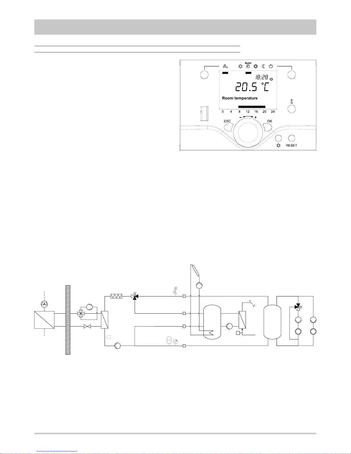
Control system
The microprocessor controller is able to manage not only the
unit itself but also all that components of the plant which allow to
realize a complete system.
The main functions of the control system are :
- room temperature control according to the outdoor
temperature (climatic control)
- domestic hot water production (management of 3 way valve,
storage tank, anti legionella cycles…)
- management of a heating and/or cooling mixed circuit (pump
and 3 way mixing valve)
- management of a heating direct circuit (only pump)
- management of a storage tank for heating and/or cooling
- management of electrical heaters for heating and domestic
hot water (3 steps logic)
- solar panels integration
- room humidity control for cooling with radiant systems
- internal programmer clock (for heating, cooling and domestic
hot water)
- digital input for electrical energy low tariff
- alarm memory management and diagnostic
- compressor and pump operating hour counter
- possibility to manage more units in cascade (maximum 16)
Besides the standard user interface present on all the units,
wired or wireless remote thermostats are available which allow
to control all the operating parameters of the unit and to acquire
the temperature in the different zones in order to realize a more
precise and comfortable control.
The unit controller is able to manage a lot of different plant
solutions enabling automatically the necessary control
algorythms according to the components which have been
connected.
The management of such components is possible through additional expansion modules which communicate with the unit by
means of an internal bus and provide all the inputs and outputs
required to full a complete system.
FS
FS
The controller is able to manage up to two zones in heating
(one by means of a mixed circuit and the other by means of a
direct circuit) and one zone in cooling (by means of a mixed
circuit).
It’s possible to realize more complex plants connecting to the
heat pump controller further expansion modules in order to
extend without limits the number of zones to be managed.
For each zone the following parameters can be set :
- set point
- daily or weekly operating time table
- climatic control curve
- room control sensor : it can be in common with the other
zones or independent (in that case it’s necessary to install
an additional room thermostat)
Page 8

8
GENERAL FEATURES
Options
The controller flexibility and the big number of options available
allow to get, for each model, a lot of different configurations that
integrate inside the heat pump many components of the plant
and allow to realize compact and tested installations.
In order to select the right configuration it is necessary to define
the type of plant to which the heat pump will be connected, both
for what concerning the heating and cooling circuits, and for
what concerning the domestic hot water management.
Option “Plant buffer tank connections"
Reversible heat pump (IP) without options Option “Integrative electrical heaters”
Domestic hot water
production
3 way valve
Allow to divert the hot water produced by the heat pump from the heating circuit
to the domestic hot water circuit.
3 way valve with
primary heat exchanger
The hot water is diverted by the three way valve on an internal heat exchanger.
An internal pump assures a correct domestic hot water ow through the other
side of the heat exchanger.
3 way valve with secondary heat
exchanger
(for integrated tank)
The hot water is diverted by the three way valve in a tank integrated in the unit
(accessory). The domestic hot water is generated istantaneously by means of an
internal heat exchanger and a modulating pump.
Acoustic
setting up
AS - Low noise setting up
Allow to reduce the noise level of the outdoor unit modifying the rotational speed
of the fan.
Integrative electrical heaters
Integrate or replace the heating power supplied by the heat pump and are
managed by the unit controller with a 3 step logic.
Soft starter Reduces the compressor start current.
Plant buffer tank connections
The hot or cold water produced by the heat pump is used to heat or cool a buffer
tank integrated in the unit (accessory) assuring a higher thermal inertia for the
plant.
In this configuration the heat pump can
heat or cool a buffer tank that increases
the thermal inertia of the plant and
operates as hydraulic separator.
NB If the integrated tank is used as
buffer tank for the plant, it can not be
used as tank for the domestic hot water
production (see option "3 way valve and
secondary heat exchanger").
FS
FS
Page 9

9
GENERAL FEATURES
In this configuration the heat pump can
be coupled to a domestic hot water
tank equipped with a coil designed for
a maximum water temperature between
55°C and 60°C.
The anti legionella cycles have to be
performed by means of electrical heaters
placed on the heat pump outlet (see
option “Integrative electrical heaters”) or
directly inside the tank.
In this configuration the heat pump can
be coupled to a domestic hot water tank
without coil.
The anti legionella cycles have to be
performed by means of electrical heaters
placed on the heat pump outlet (see
option “Integrative electrical heaters”) or
directly inside the tank.
In this configuration the heat pump can
produce instantaneously the domestic
hot water using the hot water stored
in the tank integrated in the unit (see
accessory “Integrated tank”).
The temperature of the domestic hot
water at the unit outlet is adjusted
modulating the speed of the pump on
the primary side.
The anti legionella cycles are not
necessary.
Option “Domestic hot water production”
3 way valve
3 way valve with primary heat exchanger
3 way valve with secondary heat exchanger
FS
FS
FS
FS
4
3
Page 10

10
GENERAL FEATURES
Accessories
Rubber vibration dampers
(for indoor unit)
Allow to reduce the transmission to the unit support plane of the mechanical vibrations generated by the compressor
and by the pumps in their normal operating mode.
Rubber vibration dampers
(for outdoor unit)
Allow to reduce the transmission to the unit support plane of the mechanical vibrations generated by the fans in
their normal operating mode.
Coil protection grille
(for outdoor unit)
Protects the external surface of the finned coil.
Remote thermostat
Allows operating mode selection and set point adjustment. The on board temperature sensor can be used in order
to realize a climatic control.
Remote control
(wired or wireless)
Replicates all the control and visualization functionalities of the controller installed on the unit. The on board
temperature sensor can be used in order to realize a climatic control.
Wireless transmitter
Connected to the unit controller, allows to communicate with wireless remote control and wireless outdoor
temperature sensor.
Wireless repeater Extends wireless operating range.
Wireless adaptor for
outdoor temperature sensor
Allows to transform the wired outdoor temperature sensor, standard for all the units, in a wireless sensor.
Condensate sensor In cooling mode it allows the minimum ow temperature control when condensate generation occurs.
Room hygrostat In cooling mode it allows the minimum ow temperature control according to the room humidity.
Room humidity sensor
(with or without display)
In cooling mode it allows the minimum ow temperature control according to the room dew point, calculated from
the measured room humidity.
Transformer
230V / 24V - 3VA
It assures the correct power supply for the condensate sensor and for the room humidity sensor.
Integrated tank
Integrated tank, to be installed under the unit. It can be used as storage tank for domestic hot water production
(coupled with units with option "Domestic hot water production" : "3 way valve and secondary heat exchanger") or
as buffer tank for the plant (coupled with units with option "Plant buffer tank connections".
Inside the tank a coil for solar panels integration is contained.
Pipes for solar panels
connection
Allow to move the connections of the solar integration coil, available on the tank (accessory), directly on the upper
side of the unit.
Refrigerant circuit box If a failure occurs inside the refrigerant circuit, it permits to restart the heat pump very quickly.
Page 11

11
TECHNICAL DATA AND PERFORMANCES
Frame
1
Model
31 41 51 71 91
U.M.
Power supply
230 - 1 - 50 230 - 1 - 50 230 - 1 - 50 230 - 1 - 50 230 - 1 - 50 V-ph-Hz
Technical data
Refrigerant
Type
R410A -
Compressor
Type
rotary -
Quantity
1 1 1 1 1 n°
Power steps
0 - 100 0 - 100 0 - 100 0 - 100 0 - 100 %
Oil charge
0,35 0,43 0,67 1,13 1,13 kg
Plant side heat exchanger
Type
stainless stee brazed plates -
Quantity
1 1 1 1 1 n°
Water volume
0,53 0,53 0,53 0,67 0,84 l
Fans
Type
axial with high efficiency EC motor -
Quantity
1 1 1 1 1 n°
Diameter
450 450 450 500 500 mm
Maximum rotational speed
900 900 900 900 900 rpm
Total installed power
0,15 0,15 0,15 0,21 0,21 kW
Source side heat exchanger
Type
finned coil -
Quantity
1 1 1 1 1 n°
Frontal surface
0,44 0,44 0,44 0,44 0,44 m
2
Plant side hydraulic circuit
Safety valve set point
3 3 3 3 3 bar
Expansion vessel volume
10 10 10 10 10 l
Plant side pump
Type
3 speed glandless pump -
Quantity
1 1 1 1 1 n°
Installed power
0,14 0,14 0,14 0,14 0,14 kW
Integrated tank (accessory)
Volume
120 120 120 120 120 -
Solar coil surface
1,1 1,1 1,1 1,1 1,1 m
2
Integrative electrical heaters (option)
Total installed power
9,0 9,0 9,0 9,0 9,0 kW
Power steps
0 - 33 - 66 - 100 0 - 33 - 66 - 100 0 - 33 - 66 - 100 0 - 33 - 66 - 100 0 - 33 - 66 - 100
%
Page 12
12
TECHNICAL DATA AND PERFORMANCES
Frame
1
Model
31 41 51 71 91
U.M.
Power supply
230 - 1 - 50 230 - 1 - 50 230 - 1 - 50 230 - 1 - 50 230 - 1 - 50 V-ph-Hz
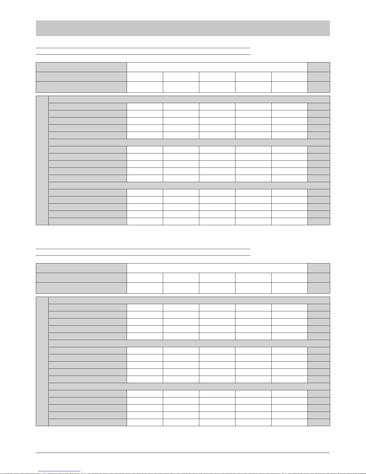
NOMINAL performances - Base acoustic setting up (AB) - Radiant plants
NOMINAL performances - Base acoustic setting up (AB) - Standard plants
Data declared according to EN 14511 The values are referred to units without options or accessories.
Data declared according to EN 14511 The values are referred to units without options or accessories.
IP
Heating A7W35 ( source : air in 7°C d.b. 6°C w.b. / plant : water in 30°C out 35°C )
Heating capacity 2,42 3,85 5,24 6,87 8,37
kW
Power input 0,85 1,35 1,88 2,44 3,00
kW
COP 2,85 2,85 2,79 2,82 2,79
-
Water flow rate plant side 417 664 905 1186 1447
l/h
Available static head plant side 60 54 47 43 40
kPa
Heating A2W35 ( source : air in 2°C d.b. 1°C w.b. / plant : water in 30°C out 35°C )
Heating capacity 1,99 3,15 4,33 5,65 6,90
kW
Power input 0,55 0,88 1,23 1,59 1,96
kW
COP 3,62 3,58 3,52 3,55 3,52
-
Water flow rate plant side 345 545 748 977 1193
l/h
Available static head plant side 62 57 51 48 46
kPa
Cooling A35W18 ( source : air in 35°C d.b. / plant : water in 23°C out 18°C )
Cooling capacity 2,52 4,00 5,46 7,14 8,72
kW
Power input 0,79 1,25 1,74 2,27 2,78
kW
EER 3,19 3,20 3,14 3,15 3,14
-
Water flow rate plant side 435 690 943 1235 1507
l/h
Available static head plant side 60 53 45 41 38
kPa
IP
Heating A7W45 ( source : air in 7°C d.b. 6°C w.b. / plant : water in 40°C out 45°C )
Heating capacity 2,35 3,72 5,11 6,67 8,15
kW
Power input 0,68 1,09 1,51 1,96 2,42
kW
COP 3,46 3,41 3,38 3,40 3,37
-
Water flow rate plant side 409 647 887 1158 1413
l/h
Available static head plant side 60 54 47 43 41
kPa
Heating A2W45 ( source : air in 2°C d.b. 1°C w.b. / plant : water in 40°C out 45°C )
Heating capacity 1,94 3,08 4,22 5,52 6,73
kW
Power input 0,68 1,08 1,50 1,95 2,39
kW
COP 2,85 2,85 2,81 2,83 2,82
-
Water flow rate plant side 337 535 732 958 1168
l/h
Available static head plant side 62 57 52 49 47
kPa
Cooling A35W7 ( source : air in 35°C d.b. / plant : water in 12°C out 7°C )
Cooling capacity 1,94 3,08 4,20 5,50 6,71
kW
Power input 0,73 1,16 1,61 2,09 2,57
kW
EER 2,66 2,66 2,61 2,63 2,61
-
Water flow rate plant side 333 529 722 945 1153
l/h
Available static head plant side 62 58 52 50 48
kPa
Frame
1
Model
31 41 51 71 91
U.M.
Power supply
230 - 1 - 50 230 - 1 - 50 230 - 1 - 50 230 - 1 - 50 230 - 1 - 50 V-ph-Hz
Page 13

13
TECHNICAL DATA AND PERFORMANCES
Frame
1
Model
31 41 51 71 91
U.M.
Power supply
230 - 1 - 50 230 - 1 - 50 230 - 1 - 50 230 - 1 - 50 230 - 1 - 50 V-ph-Hz
NOMINAL performances - Low noise acoustic setting up (AS) - Radiant plants
NOMINAL performances - Low noise acoustic setting up (AS) - Standard plants
Data declared according to EN 14511 The values are referred to units without options or accessories.
Data declared according to EN 14511 The values are referred to units without options or accessories.
IP
Heating A7W35 ( source : air in 7°C d.b. 6°C w.b. / plant : water in 30°C out 35°C )
Heating capacity 2,28 3,61 4,95 6,47 7,90
kW
Power input 0,54 0,86 1,20 1,56 1,92
kW
COP 4,22 4,20 4,13 4,15 4,11
-
Water flow rate plant side 395 625 855 1119 1366
l/h
Available static head plant side 61 55 48 44 42
kPa
Heating A2W35 ( source : air in 2°C d.b. 1°C w.b. / plant : water in 30°C out 35°C )
Heating capacity 1,89 3,00 4,11 5,37 6,56
kW
Power input 0,53 0,85 1,19 1,54 1,90
kW
COP 3,57 3,53 3,45 3,49 3,45
-
Water flow rate plant side 327 519 710 928 1134
l/h
Available static head plant side 62 58 53 50 48
kPa
Cooling A35W18 ( source : air in 35°C d.b. / plant : water in 23°C out 18°C )
Cooling capacity 2,42 3,85 5,24 6,87 8,37
kW
Power input 0,85 1,35 1,88 2,44 3,00
kW
EER 2,85 2,85 2,79 2,82 2,79
-
Water flow rate plant side 417 664 905 1186 1447
l/h
Available static head plant side 60 54 47 43 40
kPa
IP
Heating A7W45 ( source : air in 7°C d.b. 6°C w.b. / plant : water in 40°C out 45°C )
Heating capacity 2,23 3,54 4,85 6,34 7,74
kW
Power input 0,66 1,05 1,46 1,90 2,34
kW
COP 3,38 3,37 3,32 3,34 3,31
-
Water flow rate plant side 388 615 841 1101 1344
l/h
Available static head plant side 60 55 48 45 42
kPa
Heating A2W45 ( source : air in 2°C d.b. 1°C w.b. / plant : water in 40°C out 45°C )
Heating capacity 1,85 2,92 4,00 5,24 6,40
kW
Power input 0,65 1,04 1,44 1,89 2,32
kW
COP 2,85 2,81 2,78 2,77 2,76
-
Water flow rate plant side 322 508 695 909 1111
l/h
Available static head plant side 62 58 53 50 48
kPa
Cooling A35W7 ( source : air in 35°C d.b. / plant : water in 12°C out 7°C )
Cooling capacity 1,86 2,96 4,04 5,28 6,44
kW
Power input 0,79 1,25 1,73 2,26 2,77
kW
EER 2,35 2,37 2,34 2,34 2,32
-
Water flow rate plant side 319 508 693 908 1107
l/h
Available static head plant side 62 58 53 50 49
kPa
Frame
1
Model
31 41 51 71 91
U.M.
Power supply
230 - 1 - 50 230 - 1 - 50 230 - 1 - 50 230 - 1 - 50 230 - 1 - 50 V-ph-Hz
Page 14

14
TECHNICAL DATA AND PERFORMANCES
HEATING performances
The graphs allow to get the corrective factors to
be applied to the nominal performances in order
to obtain the real performances in the selected
operating conditions.
The reference nominal condition is :
A7W35
source : air in 7°C d.b. 6°C w.b.
plant : water in 30°C out 35°C
Outlet temperature
plant side :
A = 55°C
B = 45°C
C = 35°C
D = 25°C
Heating capacity
Inlet air temperature w.b. [°C]
Inlet air temperature w.b. [°C] Inlet air temperature w.b. [°C]
Power input COP
D
C
B
A
A
B
C
D
A
B
C
D
Page 15

15
TECHNICAL DATA AND PERFORMANCES
COOLING performances
The graphs allow to get the corrective factors to
be applied to the nominal performances in order
to obtain the real performances in the selected
operating conditions.
The reference nominal condition is :
A35W7
source : air in 35°C d.b.
plant : water in 12°C out 7°C
Outlet temperature
plant side :
A = 24°C
B = 18°C
C = 12°C
D = 7°C
Cooling capacity
Inlet air temperature w.b. [°C]
Inlet air temperature d.b. [°C] Inlet air temperature d.b. [°C]
Power input EER
A
B
C
D
A
B
C
D
A
B
C
D
Page 16

16
TECHNICAL DATA AND PERFORMANCES
Plant side hydraulic performances
A = unit with option “Domestic hot water production” : “3 way valve”
B = unit with option “Integrative electrical heaters”
The graphs are referred to units operating with water at the temperature of 10°C (density 1000 kg/m3).
Flow rate [ l/h ]
Pressure drops [ kPa ]
B
A
Available static head - unit without options
Flow rate [ l/h ]
Available static head [ kPa ]
7.1
3.1
4.1
5.1
9.1
Perdite di carico aggiuntive
Page 17

17
TECHNICAL DATA AND PERFORMANCES
A = unit with option “Domestic hot water production” : “3 way valve”
B = unit with option “Domestic hot water production” : “3 way valve with primary heat exchanger”
Flow rate [ l/h ]
Available static head [ kPa ]
A
9.1
11.1
5.1
3.1
7.1
B
Domestic hot water side hydraulic performances
The graphs are referred to units operating with water at the temperature of 10°C (density 1000 kg/m3).
Available static head
Page 18

18
TECHNICAL DATA AND PERFORMANCES
Operating limits
Temperature difference between unit inlet and outlet Plant side
DT max Maximum value 11
°C
DT min Minimum value 3
°C
HEATING
Inlet air temperature d.b. [°C]
Outlet temperature - plant side [°C]
I grafici sotto riportati indicano il campo di funzionamento entro cui è garantito il corretto funzionamento dell’unità.
COOLING
Inlet air temperature d.b. [°C]
Outlet temperature - plant side [°C]
Page 19

19
TECHNICAL DATA AND PERFORMANCES
Electrical data
Power supply 230 - 1 - 50 230 - 1 - 50 230 - 1 - 50 230 - 1 - 50 230 - 1 - 50
V-ph-Hz
F.L.A. Maximum total current input 6,7 8,5 10,9 14,4 18,1
A
F.L.I. Maximum total power input 1,4 1,8 2,3 3,1 3,9
kW
M.I.C.
Maximum total start current 37 46 53 83 113
A
Maximum total start current
with soft starter (option)
33 36 39 42 44
A
Unit
Power supply 230-1-50 230-1-50 230-1-50 230-1-50 230-1-50
V-ph-Hz
F.L.A. Maximum total current input 0,4 0,4 0,4 0,4 0,4
A
F.L.I. Maximum total power input 0,08 0,08 0,08 0,08 0,08
kW
Domestic hot water production pump (with option “3 way valve with primary heat exchanger”)
Power supply 230-1-50 230-1-50 230-1-50 230-1-50 230-1-50
V-ph-Hz
F.L.A. Maximum total current input 0,7 0,7 0,7 0,7 0,7
A
F.L.I. Maximum total power input 0,14 0,14 0,14 0,14 0,14
kW
Domestic hot water production pump (with option “3 way valve with secondary heat exchanger”)
Power supply
230 - 1 - 50 230 - 1 - 50 230 - 1 - 50 230 - 1 - 50 230 - 1 - 50
V-ph-Hz
400-3N-50 400-3N-50 400-3N-50 400-3N-50 400-3N-50
F.L.A.
Maximum total current input
( 230V - 1 - 50Hz )
39,1 39,1 39,1 39,1 39,1
A
Maximum total current input
( 400V - 3N - 50Hz )
13,0 13,0 13,0 13,0 13,0
A
F.L.I. Maximum total power input 9,0 9,0 9,0 9,0 9,0
kW
Integrative electrical heaters
Frame
1
Model
31 41 51 71 91
U.M.
Page 20

20
TECHNICAL DATA AND PERFORMANCES
Noise levels
Model
Sound power levels [dB]
by octave bands [Hz]
Sound power
level
Sound pressure
at 1 meter at 5 meters at 10 meters
63 125 250 500 1000 2000 4000 8000 [dB] [dB(A)] [dB(A)] [dB(A)] [dB(A)]
31
73,6 71,5 69,8 66,1 62,6 58,4 52,7 45,2 77 68 54 43 37
41
73,6 71,5 69,8 66,1 62,6 58,4 52,7 45,2 77 68 54 43 37
51
73,6 71,5 69,8 66,1 62,6 58,4 52,7 45,2 77 68 54 43 37
71
76,4 74,3 72,6 68,9 65,4 61,2 55,5 48,0 80 71 56 45 40
91
76,4 74,3 72,6 68,9 65,4 61,2 55,5 48,0 80 71 56 45 40
Outdoor unit - BASE acoustic setting up (AB)
Model
Sound power levels [dB]
by octave bands [Hz]
Sound power
level
Sound pressure
at 1 meter at 5 meters at 10 meters
63 125 250 500 1000 2000 4000 8000 [dB] [dB(A)] [dB(A)] [dB(A)] [dB(A)]
31
70,6 68,5 66,8 63,1 59,6 55,4 49,7 42,2 74 65 51 40 34
41
70,6 68,5 66,8 63,1 59,6 55,4 49,7 42,2 74 65 51 40 34
51
70,6 68,5 66,8 63,1 59,6 55,4 49,7 42,2 74 65 51 40 34
71
73,4 71,3 69,6 65,9 62,4 58,2 52,5 45,0 77 68 53 42 37
91
73,4 71,3 69,6 65,9 62,4 58,2 52,5 45,0 77 68 53 42 37
Outdoor unit - LOW NOISE acoustic setting up (AS)
Reference conditions
Performances referred to units operating in heating mode at nominal conditions A7W35.
Unit placed in free field on reflecting surface (directional factor equal to 2).
The sound power level is measured according to ISO 3744 standard.
The sound pressure level is calculated according to ISO 3744 and is referred to a distance of 1 meter from the external surface of the unit.
Model
Sound power levels [dB]
by octave bands [Hz]
Sound power
level
Sound pressure
at 1 meter at 5 meters at 10 meters
63 125 250 500 1000 2000 4000 8000 [dB] [dB(A)] [dB(A)] [dB(A)] [dB(A)]
31
73,2 63,3 48,3 31,7 31,0 22,6 20,9 21,9 74 51 36 25 19
41
74,2 64,3 49,3 32,7 32,0 23,6 21,9 22,9 75 52 37 26 20
51
74,2 64,3 49,3 32,7 32,0 23,6 21,9 22,9 75 52 37 26 20
71
75,2 65,3 50,3 33,7 33,0 24,6 22,9 23,9 76 53 38 27 21
91
75,2 65,3 50,3 33,7 33,0 24,6 22,9 23,9 76 53 38 27 21
Indoor unit
Page 21

21
TECHNICAL DATA AND PERFORMANCES
Weights
Frame
1
Model
31 41 51 71 91
U.M.
Indoor unit without options 118 122 124 131 134
kg
Indoor unit options
Domestic
hot water
production
3 way valve 3 3 3 3 3
kg
3 way valve with primary heat
exchanger
9 9 9 9 9
kg
3 way valve with secondary heat
exchanger
10 10 10 10 10
kg
Plant buffer tank connections 5 5 5 5 5
kg
Integrative electrical heaters 5 5 5 5 5
kg
Outdoor unit 58 58 58 79 79
kg
Accessories
Integrated tank 77 77 77 77 77
kg
Pipes for solar panels connection 2 2 2 2 2
kg
Refrigerant circuit box 44 48 50 58 61
kg
Components weights
Transport weights
Operating weights
Indoor unit without options 136 140 142 149 152
kg
Indoor unit options
Domestic
hot water
production
3 way valve 3 3 3 3 3
kg
3 way valve with primary heat
exchanger
9 9 9 9 9
kg
3 way valve with secondary heat
exchanger
10 10 10 10 10
kg
Plant buffer tank connections 5 5 5 5 5
kg
Integrative electrical heaters 5 5 5 5 5
kg
Outdoor unit 68 68 68 89 89
kg
Accessories
Integrated tank 95 95 95 95 95
kg
Pipes for solar panels connection 3 3 3 3 3
kg
Refrigerant circuit box 46 50 52 60 63
kg
Indoor unit without options 120 124 126 134 137
kg
Indoor unit options
Domestic
hot water
production
3 way valve 5 5 5 5 5
kg
3 way valve with primary heat
exchanger
13 13 13 13 13
kg
3 way valve with secondary heat
exchanger
14 14 14 14 14
kg
Plant buffer tank connections 7 7 7 7 7
kg
Integrative electrical heaters 6 6 6 6 6
kg
Outdoor unit 58 58 58 79 79
kg
Accessories
Integrated tank 202 202 202 202 202
kg
Pipes for solar panels connection 5 5 5 5 5
kg
Page 22

22
TECHNICAL DATA AND PERFORMANCES
Overall dimensions
Minimum operating area
Rispect the free area around the unit as shown in figure in order to guarantee a good
accessibility and facilitate maintenance and control operations.
A 600 mm
B 300 mm
C 400 mm
D 600 mm
E 200 mm
1 Plant return 1” M
2 Plant flow 1” M
3 Domestic hot water return 1” M
4 Domestic hot water flow 1” M
5 Gas line (refrigerant) 5/8”
6 Liquid line (refrigerant) 3/8”
7 Solar panel return 18 mm
8 Solar panel flow 18 mm
Unit with accessory
“Integrated tank”
53
93
90 90
80 81 83 86 90
600
600
85H2
608 7172
117 75
74
394
356
754
H1
A
B
1 2 3 4 5 6
87
3.1 - 4.1 - 5.1 7.1 - 9.1
H1 903 mm 1153 mm
H2 852 mm 852 mm
H2
with accessory
“Integrated tank”
1678 mm 1678 mm
Page 23

23
CONNECTIONS
Hydraulic connections
To design properly the hydraulic system respect the local safety
regulations in force.
It is always necessary to guarantee an appropriate water flow
through the plate heat exchanger of the unit even if is installed,
as standard, a flow switch that stops the unit if the water flow
rate is too low.
To adjust the water flow rate through the heat exchanger modify the speed of the pump by means of the 3 speed selector (if
present). For a more accurate adjustment it is reccomended the
installation of a valve on the outlet of the circuit.
It is also reccomended to install a filter on the inlet of each circuit
in order to avoid the entrance of foreign substances.
The hydraulic circuit is always equipped with safety valve and
expansion vessel. To mantain the circuit under pressure a selffilling group, that automatically fills the circuit, can be installed.
Suggestions for the hydraulic plant realization
Prepare the pipes with the minimum possible number of bends
in order to minimize pressure losses, and suitably support them
to prevent excessive stresses at the connections of the unit.
Install shut-off valves near the components that need maintenance, to allow their replacement without having to drain the
system.
Provide manual or automatic valves in the highest part of the
circuit to vent the air.
Make sure there are no leaks before insulating the pipes and
filling the system.
In order to avoid condensate generation, insulate all the pipes
using steam barrier type material.
Finned coil condensate drainage
The condensate generated by the finned coil in heating mode is
collected in the tray obtained in the basement of the outdoor unit
and can be drained connecting a pipe to the fitting supplied as
standard with all the units.
Expansion vessel setting
The precharge pressure of the expansion vessel must be
adequate to the total volume of the hydraulic circuit at which the
unit is connected.
The factory setting (p
VE-std
= 0,5 bar g) is the minimum value
necessary to avoid the presence of zones with a negative
relative pressure inside the hydraulic circuit and the risk of pump
cavitation, supposing that no parts of the plant are placed at a
higher level than the one at which the unit is installed. In that
case the precharge pressure must be increased proportionally
to the elevation of the highest part of the plant according to the
following relation :
pVE = p
VE-std
+ H
max
/ 9,81
pVE expansion vessel precharge pressure [bar g]
H
max
elevation of the highest part of the plant referred to the
unit installation level [m]
The maximum value of the precharge pressure is equal to the
safety valve pressure set.
Increasing the precharge pressure, the maximum plant volume
supported by the expansion vessel of the unit is reduced :
VI = VVE · Ce · [ 1 - ( 1 + pVE ) / ( 1 + pVS ) ]
VI plant volume supported by the expansion vessel [l]
VVE expansion vessel volume [l]
Ce expansion coefficient
pVS safety valve pressure set [bar g]
If the real plant volume is higher than such calculated volume, it
is necessary to install an additional expansion vessel of appropriate volume.
Once the hydraulic circuit has been filled, the pressure at the
expansion vessel must be slightly higher than the precharge
pressure.
If parts of the plant are placed at a lower level than the one
at which the unit is installed, verify that the components can
withstand the maximum pressure that can be present.
Water
Ethylene glycol
(percentage by volume)
Propylene glycol
(percentage by volume)
10% 20% 30% 40% 10% 20% 30% 40%
Freezing temperature [°C] 0 -3,8 -8,9 -15,7 -24,9 -3,4 -7,4 -13,1 -21,5
C
e
T
min
= 5°C , T
max
= 60°C 58,63 47,80 45,24 42,82 40,61 45,47 39,96 35,82 32,88
T
min
= 5°C , T
max
= 45°C 101,46 72,28 68,84 64,77 61,08 69,42 60,41 53,91 49,03
T
min
= -10°C , T
max
= 45°C - - - 51,85 48,57 - - 42,67 38,50
Page 24

24
CONNECTIONS
Electrical connections
The electrical wirings must be carried out by qualified personnel
according to the regulations in force at the installation time in the
country of installation. Before starting any work on the electrical
circuit make sure that the unit power supply line is disconnected
at the start.
NB Refer to the electrical diagram enclosed in the unit.
Power supply system
The power cables of the heat pump power supply line must be
connected to :
- for single phase power supply : from a single phase voltage
system provided with neutral conductor and separated earth
wire :
V = 230 V ± 10 %
f = 50 Hz
- for three phase power supply : from a symmetrical three
phase voltage system provided with neutral conductor and
separated earth wire :
V = 400 V ± 10 %
f = 50 Hz
The units are shipped completely factory wired and arranged for
the connection to the power supply.
The power cables must enter the unit through the holes on
the lateral panel and must be connected to the power supply
terminals of the unit.
The integrative electrical heaters (option) must be supplied by
a dedicated power supply line to be connected to the power
supply terminals inside the electrical board of the unit.
Heat pump power supply
The power supply cables must have an adequate section for the
power absorbed by the unit and must be chosen in conformity
with the regulations in force. Design the power supply line,
always referring to the total FLI and FLA values of the unit,
taking into account the selected options (except the integrative
electrical heaters) and the installed accessories.
Integrative electrical heaters power supply
The power supply cables must have an adequate section for the
power absorbed by the only integrative electrical heaters and
must be chosen in conformity with the regulations in force.
It is possible to connect the integrative electrical heaters either
to a single phase power supply or to a three phase power supply.
For single phase power supply heat pumps, if a three phase
power supply is used for the integrative electrical heaters,
connecting to the terminal R the same phase used to supply the
heat pump, the current absorbed by the electrical heaters on
that phase is never added to the current absorbed by the heat
pump.
For three phase power supply heat pumps, the integrative
electrical heaters power supply connection can be either single
phase or three phase without any restriction on the phase
connection.
Upstream protection
An automatic switch suitable for ensuring protection against
overcurrents and indirect contacts must be installed upstream
each power supply line.
Coordination between line switch must be carried out observing
the regulations in force on electrical safety, regarding the type of
installation and the installation ambient conditions.
Connections available for the user
The electrical board of the heat pump contains some terminals
dedicated to the connection of temperature probes, humidity
probes, pumps, valves ...
Carry out all the necessary connections in order to realize the
desired plant following the instructions reported in the section
“Inputs and outputs”.
ATTENTION
Carry out all the connections outside the heat pump avoiding the
power cables and the probe cables to be coupled.
Integrative electrical heaters connection
with single phase power supply
Integrative electrical heaters connection
with three phase power supply
Integrative
electrical heaters
Single phase
heat pump
Integrative
electrical heaters
Single phase
heat pump
Page 25

25
CONNECTIONS
Refrigerant connections
REFRIGERANT PIPES
Route the refrigerant pipes between indoor and outdoor unit with as few bends as possible. In order
to avoid to squash the bends, realize all the bends with a proper pipe bender respecting a minimum
bending radius not lower than 3,5 times the outer diameter of the tube (Fig. 1).
Select materials suitable to work at the operating pressures required. In the table are reported the
copper pipe wall thickness values suggested according to the nominal diameter of the refrigerant
connection lines. It is recommended no to use wall thickness values lower than 0,8 mm.
Fig.1
Fig.2
Fig.3
Fig.4
Fig.5
Nominal
diameter
[inch]
Outer
diameter Ø
[mm]
Thickness
[mm]
Dimensions [mm]
A B C D
Union thickness
E
1/4 6,35 0,8 9,1 9,2 6,5 13,0 1,5 ~ 2,0
3/8 9,52 0,8 13,2 13,5 9,7 20,0 1,5 ~ 2,0
1/2 12,70 0,8 16,6 16,0 12,9 23,0 2,0 ~ 2,5
5/8 15,88 1,0 19,7 19,0 16,0 25,0 2,0 ~ 2,5
During the pipes installation take care of :
• unwind the pipe, with attention, in the direction in which it has been wound;
• wrap the two pipes together with some tape before passing them through the holes in the wall to
prevent the insulation from being damaged and dust from inltrating. To facilitate this operation, it
is advisable to insert a piece of PVC pipe of a suitable diameter and of the same length as the wall
thickness into the hole in the wall.
The part of pipe in excess can be wind up taking care that the coil axis is horizontal or cutted.
In that case the pipe must be cutted and flared again operating in the following way :
1 Pipe cutting
Cut the pipe at the required lenght with a pipe cutter (Fig. 2) and operating with care in order to
prevent the pipe to be deformed. The cut must be horizontal.
2 Burrs and splinters removal
Remove burrs and splinters keeping the pipe edge downwards (Fig. 3) and clean the cut surface. If
the flare surface is deformed or splintered, refrigerant leakeages could occur.
3 Union insert
Remeber to insert the union before flaring the pipe (Fig.4).
4 Pipe flaring
Make sure that the pipe and the flaring tool are clean. When flaring the pipe it is recommended to
respect the indications reported in the table. Clamp the pipe (2 Fig. 5) in a vice (1 Fig. 5), and begin
to flare it.
It is suggested to place a drop of refrigerant oil between the rubbing parts assuring that the oil used
for the lubrification of the flare is of the same type or compatible with the oil used in the refrigerant
circuit.
If the flaring is fulfilled properly the following results are obtained (Fig. 7):
- Smooth and mirrored surface
- Smooth edges
- Flared sides of uniform lenght
N.B.: Take care to prevent swarf, dust or other impurities from dropping inside the pipes in order to
avoid damages to the refrigerant circuit.
Fig.7Fig.6
E
Page 26

26
CONNECTIONS
PIPES CONNECTION
In order to connect the refrigerant pipes comply with the following indications.
• Make sure there are not dust or other impurities in the connection zone.
• Match the flare pipe edge with the connections placed on the indoor and the outdoor units
making sure that of the perfect alignment between the connection surface and the flsred
surface.
• Tighten the union by hand.
• Torque the union with the help of a proper dinamometric tool respecting the tightening
torque reported in the table. In order to avoid tensions on the pipes it is recommended to
use a fox wedge.
TIGHTNESS CHECK (recommended)
Before fullfilling the plant vacuum operation it is advisable to check the tightness of the part
of the refrigerant circuit containing the connections between the pipes and the indoor unit. In
order to fullfill such operation proceed as described below.
• With the service valves of the outdoor unit completely shut, remove the cap from the
service tap (1-Fig.2) and the union (2-Fig.2) of the gas valve (the larger one)
• Connect the service valve to a monometric unit plus nitrogen bottle (N2).
• Pressurize the system to a maximum 40 bar using the nitrogen in the bottle. Keep the bottle
vertical during the pressurizing operation to prevent liquid nitrogen from inltrating into the
system !
• Check all the connection joints on both the outdoor and indoor units to make sure that
they are tight. Bubbles will form if leaks are present. If bubbles appear, make sure that the
unions have been tightened and that the ares are the right shape.
• Wipe off the liquid soap with a rag.
• Reduce the pressure of the nitrogen in the circuit by loosening the charge pipe from the
bottle.
• With reduced pression disconnect the nitrogen bottle.
VACUUM OPERATION (MANDATORY)
Air and humidity inside the refrigerant circuit have undesired effects on the operating ot the
unit :
• pressure increase
• unit efficiency reduction
• corrosion inside the refrigerant circuit
Therefore it is mandatory to create vacuum inside the connection refrigerant pipes.
To complete such operation proceed in the following way.
• Connect the previously described charging pipe to the vacuum pump.
• Turn on the relative knob on the monometric unit to allow the pump to access the refrigerant
circuit.
• Wait until the pressure level measured by the pressure gauge is around 3 mm Hg (400 Pa).
• As soon as the required vacuum value is reached, shut the connection cock and stop the
vacuum pump.
Nominal
diameter (")
Outer
diameter (mm) Ø
Tightening torque
Nm (kgf cm)
1/4 6,35 14 ~ 18 (140 ~ 180)
3/8 9,52 33 ~ 42 (330 ~ 420)
1/2 12,70 33 ~ 42 (330 ~ 420)
5/8 15,88 33 ~ 42 (330 ~ 420)
Page 27

27
CONNECTIONS
HOW TO COMPLETE THE INSTALLATION
• Using an Allen wrench, fully open the cocks (1-Fig.2) by turning them in an anti-clockwise
direction until the stop point is reached. Do not force any further or the retention valves
could be damaged.
• Fix the valve plugs (2-Fig.2).
• Remove the connection hose from between the vacuum station and service pressure tap
of the cock.
• Shut the service tap with the relative cap.
• If the leak test with nitrogen has not been carried out, it is advisable to check the tightness
of the lines using a leak nder.
REFRIGERANT CHARGE INTEGRATION
If the refrigerant pipes length between the outdoor and the indoor unit is higher than 10 meters it is necessary a charge integration
according to the data reported in the table.
Example Model 9.1 - Pipes length = 15 m - Charge integration = ( 15 m - 10 m ) * 50 g/m = 250 g
To complete such operation proceed in the following way.
• Use a hose pipe to connect the charge bottle (or the bottle on an electronic scale) to a service tap on the intake cock (the larger
one).
• Activate the unit in cooling mode and gradually open the connection cock (refrigerant is injected directly into the compressor).
• Shut the connection cock once the required charge has been integrated.
• Remove the connection hose between the vacuum station and the service pressure tap of the cock.
• Shut the service tap with the relative cap.
MODEL
REFRIGERANT LINES
DIAMETER
REFRIGERANT LINES
LENGTH
ELEVATION DIFFERENCE
BETWEEN I.U. AND O.U.
REFRIGERANT
ADDING CHARGE
gas liquid standard maximum standard maximum
3.1 5/8" 3/8" 7,5 m 20 m 0 m 15 m 50 g/m
4.1 5/8" 3/8" 7,5 m 20 m 0 m 15 m 50 g/m
5.1 5/8" 3/8" 7,5 m 20 m 0 m 15 m 50 g/m
7.1 5/8" 3/8" 7,5 m 20 m 0 m 15 m 50 g/m
9.1 5/8" 3/8" 7,5 m 20 m 0 m 15 m 50 g/m
Page 28

28
CONNECTIONS
PRECAUTIONS TO BE TAKEN
the units working with R410A refrigerant require particular attention during the installation
and maintenance operations in order to preserve them from possible failures connected
with the features of this refrigerant. The following precautions are therefore recommended!
• It is mandatory the vacuum operation on the refrigerant lines before opening the
connection cocks.
• For the vacuum and charge operations use proper equipment (monometric unit,
flexible pipes ecc ) different from those used for other refrigerants because they contain
oil residuals not compatible with the oil used in the R410A units. The only exception is
the vacuum pump, provided that it is equipped with a check valve that acts if the pump
accidentally stops during the vacuum operation.
• Avoid water residuals presence inside the refrigerant circuit.
• All the charging or topping operations must be performed with R410A at the liquid
condition. for this kind of operation it is required a bottle picking from the bottom and an
electronic balance, in order to take the the refrigerant at the liquid condition always present
in the bottom part of the bottle. In order to avoid splits in the mixture it is advisable to use
the bottle up to a minimum level of 30%.
• If in the refrigerant circuit a large leakeage has occured, avoid to perform partial toppings
that could modify the composition of the refrigerant mixture, completely discharge the unit
and after having performed the vacuum operation, recharge it with the refrigerant charge
required.
Pay particular attention if the indoor unit is placed at a lower level respect to the outdoor
unit ( vedi fig. B ). In this case it is necessary to realize a siphon on the refrigerant line that
operates as aspiration in cooling mode (the one with the bigger diameter).
Page 29

29
RECEIVING AND POSITIONING
Receiving
Check on receiving
As soon as the unit is received verify accurately the correspondance of the load to what was ordered to make sure that all
the material has been delivered. Check carefully that the load
has not been damaged. In case of goods with visible damages
inform promptly the haulage contractor reporting on the delivery
note the phrase “Collected with reserves owing to evident
damage”. Delivery ex works implies reimbursement of any damage on charge of the insurance company as established by
law.
Safety instructions
Observe the safety regulations in force concerning the equipment to use for unit handling or the operating formalities to follow.
Handling
Before handling the unit, check the weight of the unit , reported
both on the dataplate and on the technical documentation. Make
sure the unit to be handled with care avoiding any kind of collision that could damage the operating parts of the unit.
On the packaging of the unit are reported all the instructions
necessary for a corect handling during storing and installation.
The unit is supplied on a pallet suitable for the transport. It is
advisable to place protective material between the truck and the
unit to avoid damages to the unit. Prevent the unit or parts of it
from falling down.
Storing
The units must be stored in a dry place, repaired from sun, rain,
sand or wind.
Do not stack the units.
Maximum temperature = 60 °C
Minimum temperature = -20 °C
Humidity = 90 %
Packaging removal
Remove the packaging taking care not to damage the unit.
Check for any visible damage.
Get rid of the packaging material sending them to specialized
recycling centres (observe the regulations in force).
Positioning
The outdoor units are suitable for outdoor installation while the
indoor units are suitable for indoor installation.
Verify that the support surface can bear the weight of the selected unit and is perfectly horizontal. In order to limit the vibrations
transmitted by the unit it is possible to place, between the unit
base and the support surface, a strip of hard rubber or, if a higher level of insulation is required, vibration dampers.
In any case it is not advisable to place the unit near private offices, bedrooms or zones where very low noise levels are required.
Protect the finned coil against direct sunlight and prevailing winds and do not place the unit on dark ground (for example tarred
surfaces) to avoid the risk of overheating during operation.
Do not place the unit under roofs or near plants (even if the unit
is only partly covered) in order not to reduce the possibility of air
recirculation.
Respect the minimum operating area and verify that the installation place is not subject to flooding.
Page 30

30
START UP
Start up
The following operations must be carried out only by properly trained personnel. To make the contractual warranty effective, start
up must be carried out by authorized service centres.
Before calling the service centre it is advisable to make sure that all the installation steps have been completed (positioning, electrical
connections, hydraulic connections...).
Preliminary checks before turning on
1. Verify that :
- the unit has not suffered visible damages due to transport or positioning
- the unit is placed on an horizontal surface able to bear its weight
- the minimum operating area are respected
- the ambient conditions comply with the provided operating limits
- the hydraulic and electrical connections has been carried out correctly
2. Disconnect the unit power suply line at the start and make sure that :
- the unit power supply line complies with the regulations in force
- the screws, fastening the electrical cables to the components inside the electrical panel of the unit, are well tightened (vibrations
during transport phases could have caused some loosening)
3. Connect the unit power supply line and verify that :
- the voltage of the power supply line complies with the the nominal one of the unit
- for three phase power supply units, the unbalance between the phases is lower than 2% (a higher value produces an excesive
current input on one or more phases causing possible damages to the electrical components of the unit)
NOTE. Example of phase unbalance calculation
- Read the value of the three line voltages using a voltmeter :
line voltage between phases L1 and L2 : V
1-2
= 390 V
line voltage between phases L2 and L3 : V
2-3
= 397 V
line voltage between phases L3 and L1 : V
3-1
= 395 V
- Calculate the difference between the maximum and minimum value of the measured line voltages :
ΔV
max
= max ( V
1-2
; V
2-3
; V
3-1
) - min ( V
1-2
; V
2-3
; V
3-1
) = V
2-3
- V
1-2
= 397 - 390 = 7 V
- Calculate the average line voltage value :
Δ
average
= ( V
1-2
+ V
2-3
+ V
3-1
) / 3 = ( 390 + 397 + 395 ) / 3 = 394 V
- Calculate the percentage unbalance value :
ΔV
max
/ V
average
x 100 = 7 / 394 x 100 = 1,78 % < 2 %
Turning on
Start all the plant components necessary to guarantee an adequate water flow rate on the plant hydraulic circuit.
Activate the unit in heating or in cooling mode operating on the user interface or on the remote controls and insert a set point suitable
to require the unit to work.
Page 31

31
CONTROL SYSTEM
Control system configuration
The control system can be configured in different ways in order
to adapt itself to the user needs and to the kind of plant managed
by the heat pump.
The simpler configuration consists of unit controller (A), outdoor
air temperature sensor (B) and user interface (C). Such components are always supplied with the unit and allow to realize a
climatic control based only on the outdoor air temperature.
Starting from this configuration it is possible to add, as accessories, remote thermostats (D) or remote controls (E) in order to realize
a climatic control based also on the room temperature of each zone and to control the heat pump at a distance.
The communication between the devices of the control system can be carried out through wired or wireless connections. To realize a
wireless network are available, as accessories : wireless transmitter (F) to be connected to the heat pump controller, wireless adaptor
for outdoor temperature sensor (G) , wireless remote control (H) and wireless repeater (I) to be used to amplify the signal when the
distance between the devices is large.
Page 32

32
CONTROL SYSTEM
Heating and cooling circuits
The controller of the heat pump is able to manage up to two zones :
- zone 1 : heating and cooling
- zone 2 : only heating
The management of further zones, possibile by means of additional zone controllers, is not treated in this manual.
For each zone can be set :
- set point
- daily or weekly operating time table
- climatic curve
- room control sensor
The management of such zonesis performed by means of three independent distribution circuits.
The heating circuit 1 and the cooling circuit 1 control the same plant components (pump and mixing valve). Such circuits can be managed either as unmixed circuits or as mixed circuits (in this case for the mixing valve management the installation of a temperature
sensor on the flow of the circuit is necessary).
The heating circuit P can also be managed together with the heating circuit 1, sharing set point and room temperature sensor. In that
case zone 2 is not present. Heating circuit P management is defined by parameter 46 set on the user interface of the unit.
The management of each zone can be realized by means of :
- user interface : the climatic control is based only on the outdoor air temperature
- remote control : the climatic control is based both on the outdoor air temperature and on the room temperature acquired by the
temperature sensor contained inside the remote control
- remote thermostat : the climatic control is based both on the outdoor air temperature and on the room temperature acquired by
the temperature sensor contained inside the remote thermostat
A user interface is each remote control used only for the visualization of the unit operating status and for the parameter setting (internal temperature sensor not used).
In order to set properly the remote control as a user interface the parameters reported
in the table must be set.
For each zone it is possible to install a remote control or a remote thermostat (it is not possible to install both).
If a remote thermostat or a remote control is present, the management of each zone is always possible also through the unit user
interface.
The diagrams reported below show the different possible configurations of the system and the parameters to be set.
Configuration 1
Zone 1 : management through user interface
Zone 2 : not present
Configuration 2
Zone 1 : management through user interface
Zone 2 : management through user interface
Function Distribution circuit
Zone 1
Heating
and cooling
HC1 Heating circuit 1 mixed
CC1 Cooling circuit 1 mixed
Zone 2 Heating HCP Heating circuit P NOT mixed
User interface
46
HCP management together with HC1
User interface
40 Operator unit 1
42 HC1 + HCP
48 None
User interface
46 HCP management independent
Zone 1
HC1/CC1 HCP
Zone 2 Zone 1
HC1/CC1 HCP
Zone 2
Page 33

33
CONTROL SYSTEM
Remote
thermostat 1
Configuration 3
Zone 1 : management through remote control
Zone 2 : not present
Configuration 5
Zone 1 : management through user interface
Zone 2 : management through remote control or thermostat
User interface
46
HCP management together with HC1
Remote control 1
40 Room unit 1
42 HC1 + HCP
46
HCP management together with HC1
48 HC1
User interface
46 HCP management independent
Remote control 1
40 Room unit P
42 -
Remote thermostat 1
ru 3
Zone 1
HC1/CC1 HCP
Zone 1
HC1/CC1 HCP
Zone 2
Remote
control 1
Remote
control 1
Configuration 4
Zone 1 : management through remote control or thermostat
Zone 2 : management through user interface
Configuration 6
Zone 1 : management through remote control or thermostat
Zone 2 : management through remote control or thermostat
User interface
46 HCP management independent
Remote control 1
40 Room unit 1
42 HC1
Remote thermostat 1
ru 1
Interfaccia utente
46 HCP management independent
Remote control 1
40 Room unit 1
42 -
Remote thermostat 1
ru 1
Remote control 2
40 Room unit P
42 -
Remote thermostat 2
ru 3
Zone 1
HC1/CC1 HCP
Zone 1
HC1/CC1 HCP
Zone 2
Remote
control 1
Remote
thermostat 2
Remote
control 2
Remote
thermostat 1
Remote
control 1
Remote
thermostat 1
Page 34

34
CONTROL SYSTEM
min.
m
Control system devices installation
REMOTE THERMOSTAT AND REMOTE CONTROL ( WIRED OR WIRELESS )
They should be located in the main room of the zone they manage
taking into account the following criteria :
- the place of installation should be chosen so that the sensor
can measure the room temperature as accurately as possible without being influenced by the direct solar radiation or by
other hot or cold sources (about 1,5 meters above the floor);
- in the case of wall mounting, enough clearance above the device must remain, enabling it to be fitted and removed.
The power supply of the remote thermostat and of the remote control is supplied by the mounting base. When the devices are removed from their base, power is cut off and the devices are out of operation. The wireless remote control is powered by three 1,5 V
alkaline batteries type AA (LR06).
Remote thermostat
Remote control
1 CL+ BSB data
2 CL- BSB ground
1 CL+ BSB data
2 CL- BSB ground
3 G+ Power supply
Wired
Wireless
Page 35

35
CONTROL SYSTEM
A LED
B Button
A LED
B Button
C Connector X60
A LED
B Button
OUTDOOR AIR SENSOR
The device must be installed outside the building. The sensor is
connected to the controller of the unit or to the wireless adaptor
through a two wire cable ( the wires are interchangeable ).
WIRELESS ADAPTOR FOR OUTDOOR TEMPERATURE
SENSOR
The device must be installed inside the building. The device is
powered by two 1,5 V alkaline batteries type AAA (LR03). The
outdoor air sensor is connected to the adaptor through a two wire
cable ( the wires are interchangeable ).
WIRELESS TRANSMITTER
The transmitter must be connected to the X60 terminal of the
heat pump controller. Before connecting the transmitter, the controller must be disconnected from power.
Do NOT install the transmitter inside metal casing.
WIRELESS REPEATER
The device must be installed inside the building. The device is powered through the mounting base by the power pack supplied with
the device ( the wires are interchangeable ).
Page 36

36
CONTROL SYSTEM
Wireless devices connection
WIRELESS REMOTE CONTROLLER
WIRELESS ADAPTOR FOR OUTDOOR TEMPERATURE SENSOR
WIRELESS REPEATER
The wireless devices should be located in such a way that the
transmission is as interference free as possible. The following
criteria must be observed :
- do not place the devices in the vicinity of electrical cables,
strong magnetic fields or equipments as PC, televisions, micro wave ovens...
- do not place the devices near large metal structures or constructional elements with fine meshes as special glass or
special concrete;
- the distance of the devices from the transmitter should not
exceed 30 meters or 2 floors.
In order to fulfill the connection two stages are necessary.
Connection establishment : wireless devices are connected to
the controller of the heat pump. This stage must be done before
installing the devices so that all the parts are within easy reach.
Connection test : the signal quality is checked. The devices
must be already installed in their final position. If the test fails
it’s necessary to modify the position of the devices or to add a
wireless repeater in order to extend wireless operating range.
Connection establishment
Verify if the wireless transmitter is connected to the heat pump
controller and that the controller is powered.
Verify if the batteries of the wireless remote controller are properly installed.
Press the button on the wireless transmitter for at least 8 seconds. The led starts blinking at high frequency.
Press the OK button on the wireless remote controller to enter
the menu PROGRAMMING.
Press the INFO button for at least 3 seconds, select the operating level COMMISSIONING and press OK.
Select the menu WIRELESS and press OK.
Set the parameter 40 “USED AS” according to the use of the
component and press OK.
Select YES with the knob and press OK.
The process of opening the connection is started. The display
shows the progress of opening the connection in %. The process
can take 2 to 120 seconds.
The connection is established when “DEVICE READY” appears
and the led on the wireless transmitter extinguishes.
Connection test
Press the OK button on the wireless remote controller to enter
the menu PROGRAMMING.
Press the INFO button for at least 3 seconds, select the operating level COMMISSIONING and press OK.
Select the menu WIRELESS and press OK.
Set the parameter 121 “TEST MODE” as ON and press OK.
The digits on the left show the telegrams sent, the digits on the
right the telegrams received. The test will be ended after 24 telegrams. The test is considered successful when at least 50% of
the telegrams sent have been received.
Connection establishment
Verify if the wireless transmitter is connected to the heat pump
controller and that the controller is powered.
Verify if the batteries of the wireless adaptor are properly installed.
Press the button on the wireless transmitter for at least 8 seconds. The led starts blinking at high frequency.
Press the button on the wireless adaptor for at least 8 seconds.
Also the led on the adaptor starts blinking at high frequency.
The connection is established when the led on the wireless transmitter extinguishes.
Press briefly the button on the wireless adaptor until also the led
on the wireless adaptor extinguishes.
Connection test
Press the button on the wireless adaptor for a maximum of 8
seconds. The led on the adaptor starts blinking at low frequency.
If the connection works correctly the led on the wireless transmitter flashes briefly at 10 second intervals.
After the test press briefly the button on the wireless adaptor
until the led on the adaptor extinguishes.
The test can be aborted pressing the ESC button
Connection establishment
Verify if the wireless transmitter is connected to the heat pump
controller and that the controller is powered.
Verify if the wireless repeater is properly powered.
Press the button on the wireless transmitter for at least 8 seconds. The led starts blinking at high frequency.
Press the button on the wireless repeater until also the led on
the repeater starts blinking at high frequency.
The connection is established when the led on the wireless transmitter extinguishes.
Press briefly the button on the wireless repeater until also the led
on the wireless repeater extinguishes.
Connection test
Press the button on the wireless repeater for a maximum of 8 seconds. The led on the repeater starts blinking at low frequency.
If the connection works correctly the led on the wireless transmitter flashes briefly at 10 second intervals.
After the test press briefly the button on the wireless repeater
until the led on the repeater extinguishes.
The test can be aborted pressing the ESC button.
Page 37

37
CONTROL SYSTEM
Control system using
The user interface, placed on the frontal panel, allows the complete control of the system permitting to visualize and modify all
the operating parameters of the unit.
The remote control (wired or wireless) replicates all the functions
available through the user interface. The only differences compared to the user interface are the presence of a temperature
sensor to measure the room temperature of the zone managed
by the remote control and the replacement of the “Reset” button
with the “Occupancy” button.
The remote thermostat contains a temperature sensor to measure the room temperature but allows the access to a limited
number of functions.
DHW button
BSB port
ESC button
DHW button
ESC button
KNOB
INFO button
KNOB
OCCUPANCY button
HEATING button
COOLING button
OCCUPANCY button
OK button
HEATING button
KNOB COOLING button
RESET button
OK button
INFO button
HEATING button
Room temperature
20.5 C
18:28
20.5 C
Room temperature
20.5 C
18:28
Page 38

38
CONTROL SYSTEM
HEATING button
Allows to select the active heating mode (indicated by a bar under the corresponding symbol).
Heating mode Automatic
- room temperature controlled according to the set time table (switching between Comfort and Reduced set point)
- protective functions active
- ECO functions active (automatic summer/winter changeover and automatic 24 hour heating limit)
Heating mode Comfort
- room temperature controlled according to Comfort set point
- protective functions active
- ECO functions not active (automatic summer/winter changeover and automatic 24 hour heating limit)
Heating mode Reduced
- room temperature controlled according to Reduced set point
- protective functions active
- ECO functions active (automatic summer/winter changeover and automatic 24 hour heating limit)
Heating mode Frost Protection
- room temperature controlled according to Frost Protection set point
- protective functions active
- ECO functions active (automatic summer/winter changeover and automatic 24 hour heating limit)
COOLING button
Allows to select the cooling mode (indicated by a bar under the corresponding symbol).
Cooling mode Automatic
- room temperature controlled according to the set time table (switching between Comfort set point and OFF)
- protective functions active
- cooling enabled according to the outdoor temperature
Cooling mode OFF
- protective functions active
REMOTE THERMOSTAT DISPLAY
USER INTERFACE AND REMOTE CONTROL DISPLAY
Heating : Comfort set point
Heating : Reduced set point
Heating : Frost Protection set point
Cooling : Comfort set point
Wait
Change batteries
Holiday function active
Reference to heating circuit
Alarm messages
Maintenance messages
Info level
Programming level
ECO functions active
Page 39

39
CONTROL SYSTEM
DHW button
Allows to select the domestic hot water heating mode (indicated by a bar under the corresponding symbol).
Domestic hot water heating mode ON
- domestic hot water temperature controlled according to the set time table
- protective functions active
Domestic hot water heating mode OFF
- protective functions active
Domestic hot water heating mode FORCED
Pressing for at least 3 seconds the DHW button the domestic hot water tank forced charging function is activated.
RESET button
Allows to cancel pending error messages and to ignore the scheduled delays at the unit switch on avoiding undesired
waiting times during commissioning or fault tracing. This function should NOT be used in normal operation.
OCCUPANCY button
When a room is not used for a short period of time, pressing the OCCUPANCY button is possible to lower the room
temperature in order to save energy. When the room is occupied again, pressing again the OCCUPANCY button, normal
operation is restored.
The function is active only in automatic heating mode or in automatic cooling mode :
- in heating : changeover from Comfort heating to Reduced heating
- in cooling : changeover from Comfort cooling to cooling OFF
The function remains active until the next operating mode change set through the time table program.
KNOB
Allows to modify the Comfort set point (in heating or in cooling according to the active operating mode). Press the OK
button to confirm.
Allows moreover to select the different parameters inside the menu and to select the values of each parameter.
INFO button
Pressing the INFO button various informations about the operating status of the system can be displayed. The list of
informations changes according to the type of unit, the plant configuration and the active operating mode.
When error or maintenance messages are displayed, pressing the INFO button further details about the event are provided.
ECO FUNCTIONS
Automatic summer/winter changeover
This function is used to switch on or off the heating mode in the course of the year according to the outdoor air temperature. It is
possible to extend or to shorten the period of time during which the heating mode is active modifying the threshold of the outdoor air
temperature at which the changeover takes place.
The threshold set is independent for each circuit (parameter 730 for heating circuit 1, parameter 1330 for heating circuit P). Increasing
the threshold the heating mode will be switched on earlier and switched off later. To take into account the building thermal inertia the
outdoor temperature is attenauted.
Automatic 24 hour heating limit
This function is used to switch on or off the heating mode in the course of the day according to the outdoor air temperature. This function allows, in the intermediate seasons (spring and autumn), to respond to sudden changes of the outdoor air temperature.
It is possible to extend or to shorten the period of time during which the heating mode is active modifying the temperature threshold
at which the changeover takes place. The threshold is calculated adding to the Comfort set point a differential. The differential set is
independent for each circuit (parameter 732 for heating circuit 1, parameter 1332 for heating circuit P). Increasing the differential the
heating mode will be switched on earlier and switched off later.
To take into account the building thermal inertia the outdoor temperature is attenauted.
Page 40

40
CONTROL SYSTEM
Control system programming
Menu structure
The settings that can not be modified directly through the buttons of the user interface and of the remote controls are accessible
through the programming parameters, grouped inside the various programming menus. The menus concerning functions which are
not active are automatically hidden.
It is possible to enter the programming menus with different user names. Each user has different authorizations concerning the possibility to visualize and modify the parameters :
- End user E
- Commissioning I
- Heating engineer F
The programming menus are accessible only through the user interface and the remote control.
To enter the programming menus :
- return to the main display (from whatever position press repeatedly the ESC button)
- press the OK button
- press the INFO button for at least 3 seconds
- select the user name with the knob and press the OK button
- select the desired menu and press OK
To modify the parameters inside the menus :
- select the desired parameter with the knob
- press the OK button to modify the parameter
- select the new value with the knob
- press the OK button to confirm the new value or the ESC button to cancel
Menu Level Parameter Function
Hour and date
E 1
Hour / minutes
E 2
Day / Month
E 3
Year
Operator section
E 20
Language
Time table 1
Heating circuit 1
E 500
Preselection
E 501
Phase 1 on
E 502
Phase 1 off
E 503
Phase 2 on
E 504
Phase 2 off
E 505
Phase 3 on
E 506
Phase 3 off
E 516
Default values
Time table 3
Heating circuit P
E 540
Preselection
E 541
Phase 1 on
E 542
Phase 1 off
E 543
Phase 2 on
E 544
Phase 2 off
E 545
Phase 3 on
E 546
Phase 3 off
E 556
Default values
Time table 4
Domestic hot water
E 560
Preselection
E 561
Phase 1 on
E 562
Phase 1 off
E 563
Phase 2 on
E 564
Phase 2 off
E 565
Phase 3 on
E 566
Phase 3 off
E 576
Default values
Page 41

41
CONTROL SYSTEM
Menu Level Parameter Function
Time table 5
Cooling circuit 1
E 600
Preselection
E 601
Phase 1 on
E 602
Phase 1 off
E 603
Phase 2 on
E 604
Phase 2 off
E 605
Phase 3 on
E 606
Phase 3 off
E 616
Default values
Holidays program
Heating circuit 1
E 642
Start
E 643
End
E 648
Operating level
Holidays program
Heating circuit P
E 662
Start
E 663
End
E 668
Operating level
Heating circuit 1
E 710
Comfort set point
E 712
Reduced set point
E 714
Frost Protection set point
E 720
Climatic curve slope
E 730
Summer/winter changeover temperature
Cooling circuit 1
E 901
Operating mode
E 902
Comfort set point
E 907
Release
Heating circuit P
E 1300
Operating mode
E 1310
Comfort set point
E 1312
Reduced set point
E 1314
Frost Protection set point
E 1320
Climatic curve slope
E 1330
Summer/winter changeover temperature
Domestic hot water
E 1610
Nominal set point
E 1612
Reduced set point
Service
Special operations
E 7120
Economy mode
E 7141
Emergency operation
Diagnostic
heat source
E 8410
Heat pump return temperature
E 8411
Set point heat pump return temperature
E 8412
Heat pump ow temperature
E 8427
Source return temperature
E 8429
Source ow temperature
Diagnostic
consumers
E 8700
Outdoor temperature
E 8701
Minimum outdoor temperature
E 8702
Maximum outdoor temperature
E 8740
Room temperature heating circuit 1
E 8741
Set point room temperature heating circuit 1
E 8743
Flow temperature heating circuit 1
E 8744
Set point ow temperature heating circuit 1
E 8756
Flow temperature cooling circuit 1
E 8757
Set point ow temperature cooling circuit 1
E 8800
Room temperature heating circuit P
E 8801
Set point room temperature heating circuit P
E 8803
Set point ow temperature heating circuit P
E 8830
Temperature 1 Domestic Hot Water
E 8831
Set point Domestic Hot Water temperature
E 8980
Temperature 1 Buffer
E 8981
Set point Buffer temperature
E 8982
Temperature 2 Buffer
E 9031
Relay output QX1
E 9032
Relay output QX2
E 9033
Relay output QX3
E 9034
Relay output QX4
E 9035
Relay output QX5
E 9036
Relay output QX6
Page 42

42
CONTROL SYSTEM
Remote thermostat programming
Remote control (wired o wireless) programming
Functions available for the use
The configuration parameters of the remote thermostat must be set on the device itself.
A long press (longer than 3 seconds) on the OCCUPANCY button allows to enter the Programming
menu from which is possible to modify the parameters listed in the table.
When a parameter is selected the current value
blinks. Use the knob to adjust the value of the parameter. Press briefly the OCCUPANCY button to
select the following parameter.
Press the HEATING button to escape from the Programming menu.
The configuration parameters of the remote control must be set on the device itself. Entering the “Operator section” menu it is possible
to adjust the parameters listed in the table.
Heat pump type setting
It is possible to set the type of heat pump (water-water or brine-water) modifying the parameter 5800.
Hour, date and language setting
In order to set hour and date enter the “Hour and date” menu and modify the parameters 1, 2 and 3. It is possible to select the desired
language for the user interface and for each remote control through the “Operator section” menu (parameter 20).
Time tables setting
When the selected operating mode is “Automatic”, the circuits are activated according to the set time tables.
It is possible to set the time table independently for each circuit (heating circuit 1, heating circuit P, domestic hot water circuit, cooling
circuit 1).
For the cooling circuit 1 it is possible to select, through the parameter 907, whether :
- keep the circuit always activated (24 hour per day)
- activate the circuit according to time table 5
- activate the circuit according to heating circuit 1 time table
For each time table it is possible to specify the program to use in the different days of the week :
- daily (a different program for each day of the week)
- weekly (same program for all the days of the week)
- week end (a program from Monday to Friday and another program from Saturday to Sunday)
For each program it is possible to specify 3 different operating phases per day (6 switch on or switch off events per day).
All the programs can be restored to the dafault values.
For details on the settings of parameters 40, 42, 44 and 46 see paragraph “Heating and cooling circuits”.
The room temperature sensor contained inside the remote control can be calibrated adding an offset (parmeter 54) to the value read.
Parametro Funzione
ru
Remote thermostat use
ru = 1 management heating circuit 1
ru = 3 management heating circuit P
P1
Save settings
P1 = 1 save pressing HEATING button or without confirmation (for
timeout)
P1 = 2 save pressing HEATING button
P2
Operation lock
P2 = 0 lock disabled
P2 = 1 all the buttons are locked (access to Programming menu
granted)
Menu Level Parameter Function
Operator section
E 20
Language
F 22
Informations
F 26
Operation lock
F 27
Programming lock
I 28
Save settings
I 40
Renote control use
I 42
Heating circuits assignment
I 46
Operation heating circuit P
I 48
Action OCCUPANCY button
F 54
Room temperature sensor offset
Page 43

43
Comfort
Reduced
Frost Protection
Holidays setting
It is possible to set a holidays period for the heating circuit 1 and for the heating circuit P.
For each period it is possible to specify the start and the end date and the set point to be adopted during the holidays period.
Operating mode selection for heating and cooling circuits
Heating circuit 1 : through the Heating button
Heating circuit P : through the Heating button (if the management of the heating circuit 1 and P is in common) or through the
parameter 1300 (if the management is independent)
Cooling circuit 1 : through the Cooling button o through the parameter 901
Set point setting
For each heating circuit 3 set points can be set : Comfort, Reduced and Frost Protecion.
For each cooling circuit only one set point can be set : Comfort.
The set points of the heating circuits are related one each other : the Comfort set point can not be lower than the Reduced set point,
the Reduced set point can not be lower than the Frost Protection set point and the Frost Protection set point can not be lower than
4°C.
All the set points can be adjusted through the parameters.
The Comfort set points of the heating circuit 1 and of the cooling circuit 1 can also be adjusted by means of the knob of the user
interface.
The Comfort set point of each circuit can also be adjusted by means of the knob of the remote control or of the remote thermostat
assigned to that circuit (if present).
Heating circuits climatic curves setting
The climatic curves allow to calculate the flow temperature
set point of each circuit according to the outdoor air temperature in order to keep the room temperature as near as
possible to the set value.
The curves are referred to a room set point of 20°C . If the
set point is modified, the curve automatically change to
adapt themselves to the new value.
It is possible to modify the parameters of the climatic curves
in order to fit the features of the plant and of the building.
The higher the slope of the curve, the higher is the change of
the flow temperature set point for low values of the outdoor
air temperature.
If the room temperature is correct for high outdoor air temperature but is lower than the set point for low outdoor air
temperature, the slope of the curve must be increased and
vice versa.
If on the other hand the room temperature is always lower
or higher than the set point the curve must be translated without modifying its slope.
Heating circuit 1 Heating circuit P Cooling circuit 1
Comfort set point parameter 710 parameter 1310 parameter 902
Reduced set point parameter 712 parameter 1312 -
Frost Protection set point parameter 714 parameter 1314 -
Maximum Comfort set point parameter 716 parameter 1316 40 °C
Minimum Comfort set point - - 15 °C
Heating circuit 1
Heating circuit P
Climatic curve slope parameter 720 parameter 1320
Climatic curve displacement parameter 721 parameter 1321
CONTROL SYSTEM
Page 44

44
CONTROL SYSTEM
Inputs and outputs
The following table shows the list of the inputs and outputs available on the controller of the heat pump along with the expected use.
Some inputs and outputs can be configured in a different way by the user in order to manage other plant components which are not
contained inside the heat pump.
(1) Available for the user only if as “Domestic hot water production” option has not been chosen “3 way valve with primary heat
exchanger” or “3 way valve with secondary heat exchanger”.
(2) Available for the user only if the “Integrative electrical heaters” option has not been chosen.
ID Use Description Features
Available
for the user
Inputs
B9 B9 Outdoor air temperature temperature sensor NTC 1K
B91 B91
Source heat exchanger inlet temperature
(finned coil inlet)
temperature sensor NTC 10K
B84 B84 Liquid line temperature temperature sensor NTC 10K
B71 B71 Plant heat exchanger inlet temperature temperature sensor NTC 10K
B21 B21 Plant heat exchanger outlet temperature temperature sensor NTC 10K
B3 B3 Domestic hot water buffer temperature temperature sensor NTC 10K
B1 B1 Heating circuit 1 ow temperature temperature sensor NTC 10K
BX1 B4 Plant buffer temperature temperature sensor NTC 10K x
BX2 B41 Plant buffer temperature - bottom temperature sensor NTC 10K x
BX3 B31 Domestic hot water buffer temperature - bottom temperature sensor NTC 10K x (1)
BX4 B38 Instantaneous domestic hot water ow temperature temperature sensor NTC 10K x (1)
BX5 B6 Solar collector temperature temperature sensor NTC 10K x
H1 H1 Instantaneous domestic hot water ow switch voltage free digital input
H3 H3 Room humidity sensor
voltage free digital input
0-10 Vdc input
x
E9 E9 Low pressure switch 230 Vac digital input
E10 E10 High pressure switch 230 Vac digital input
EX1 - - 230 Vac digital input x
EX2 E24 Plant ow switch 230 Vac digital input
EX3 E5 Low tariff 230 Vac digital input x
EX4 E6 Electrical power supply lock 230 Vac digital input x
EX5 - - 230 Vac digital input x
EX6 - - 230 Vac digital input x
EX7 - - 230 Vac digital input x
Outputs
K1 K1 Compressor 2 A - 230 Vac
Q2 Q2 Heating circuit 1 pump 2 A - 230 Vac
Q3 Q3 Domestic hot water 3 way valve 2 A - 230 Vac
Q8 Q8 - 2 A - 230 Vac
Q9 Q9 Plant pump 2 A - 230 Vac
QX1 K25 Integrative electrical heaters - step 1 2 A - 230 Vac x (2)
QX2 K26 Integrative electrical heaters - step 2 2 A - 230 Vac x (2)
QX3 - - 2 A - 230 Vac x
QX4
Q33
Q34
Domestic hot water pump
Instantaneous domestic hot water pump
2 A - 230 Vac x (1)
QX5 Y22 Reversing cycle valve 2 A - 230 Vac
QX6
Q20Q5Heating circuit P pump
Solar collector pump
2 A - 230 Vac x
Y1/Y2 Y1/Y2 Heating circuit 1 3 way mixing valve 2 A - 230 Vac
UX K19 Fan 0-10 Vdc
Page 45

45
CONTROL SYSTEM
Alarms
Alarms table
Alarms activation and reset
The controller is able to perform a complete diagnosis of the unit
detecting all the operating faults and notifying different alarms.
The activation of an alarm implies :
- involved consumers locked
- alarm icon shown on the display
- event recorded in the alarm history
To show the details about the active alarm press the INFO button.
Alarms that can damage the unit or the plant require a manual
reset that implies that the operator has to reset manually the
controller. It is advisable to verify accurately the cause that originated the alarm and to make sure that the problem has been
solved before restarting the unit. In any case the unit will restart
only if the cause of the alarm has disappeared.
For the manual reset alarms, pressing the INFO button, along
with the details about the alarm, also the message “Reset ?” will
appear. Press the OK button. When the message “Yes” blinks
press again the OK button to confirm the alarm reset.
The less critical alarms have an automatic reset. As soon as the
minimum compressor switch off time has elapsed the controller
tries to reset the alarm. If the cause that originated the alarm has
disappeared, the unit starts working again and the alarm icon is
no more shown on the display. Some of these alarms become
manual reset alarms if the number of events in an hour exceeds
a fixed threshold.
It is possible to reset the active alarms also through the RESET
button. In that case the scheduled delays at the unit switch on
are ignored avoiding undesired waiting times during commissioning or fault tracing. This function should NOT be used in normal
operation.
Alarm history
The controller allows to save the last 10 alarms occured during
the unit operation. For each event the following details are recorded :
- alarm code
- hour
- date
Such details can be displayed entering the “Errors” menu (parameters from 6800 to 6819).
When the number of saved events is higher than 10 the following
events are saved deleting the oldest alarms.
The controller diagnostic takes into account, besides the alarms reported in the table, many other alarm codes the meaning of which
is indicated on the unit display when the corresponding alarm becomes active. Such alarms are not critical and don’t lock the heat
pump operation.
Note:
(1) A = automatic reset , M = manual reset , A / M = manual reset only if the number of events in an hour is higher than 3.
Code
Alarm Reset
(1)
Input Heat pump lock
10 Outdoor air temperature sensor A B9 No
33 Plant side flow temperature sensor A B21 No
35 Source side return temperature sensor A B91 Si
39 Liquid sensor A B84 Si
44 Plant side return temperature sensor A B71 No
106 Sorce side temperature too low M - Si
201 Plant side frost protection alarm A B21 Si
204 Fans overload A / M E14 Si
222 High pressure during heat pump operating A / M E10 Si
223 High pressure during heating circuit start M E10 Si
224 High pressure during domestic hot water circuit start M E10 Si
225 Low pressure A / M E9 Si
247 Defrosting fault A / M - Si
356 Plant side flow switch A / M E24 Si
Page 46

46
CONTROL SYSTEM
Controller technical data
Power supply
230 Vac (+10% / -15%)
50 Hz / 60 Hz
max 11 VA
Safety class (EN 60730) II
Degree of protection (EN 60529) IP 00
Operating room temperature (not condensing) -20°C ... 50°C
Storing room temperature -20°C ... 65°C
Power supply bus BSB
Communication
wired BSB bus
5 wire connection not interchangeable (3m max)
Safety class (EN 60730) III
Degree of protection (EN 60529) IP 20
Operating room temperature (not condensing) 0°C ... 50°C
Storing room temperature -20°C ... 65°C
Power supply bus BSB
Communication
wired BSB bus
2 wire connection not interchangeable (200m max)
Safety class (EN 60730) III
Degree of protection (EN 60529) IP 20
Operating room temperature (not condensing) 0°C ... 50°C
Storing room temperature -20°C ... 65°C
Room temperature sensor
Range : 0°C ... 50°C
Resolution : 0,1°C
Tolerance : 1,0°C
Power supply 3 alkaline batteries 1,5 V type AA (LR06)
Communication
wireless BSB bus
frequency 868 MHz
Safety class (EN 60730) III
Degree of protection (EN 60529) IP 20
Operating room temperature (not condensing) 0°C ... 50°C
Storing room temperature -20°C ... 30°C
Room temperature sensor
Range : 0°C ... 50°C
Resolution : 0,1°C
Tolerance : 1,0°C
Power supply
5,5 Vdc (X60 terminal of the controller)
max 0,11 VA
Communication 6 wire connection not interchangeable (1,5m max)
Safety class (EN 60730) III
Degree of protection (EN 60529) IP 40
Operating room temperature (not condensing) 0°C ... 50°C
Storing room temperature -20°C ... 65°C
Controller
User interface
Remote thermostat and wired remote control
Comando remoto wireless
Wireless transmitter
Page 47

47
CONTROL SYSTEM
Power supply
230 Vac (+10% / -15%)
50 Hz (+6% / -6%)
max 0,5 VA
Communication
wireless BSB bus
frequency 868 MHz
Safety class (EN 60730) III
Degree of protection (EN 60529) IP 20
Operating room temperature (not condensing) 0°C ... 50°C
Storing room temperature -20°C ... 65°C
Power supply 2 alkaline batteries 1,5 V type AAA (LR03)
Communication
wireless BSB bus
frequency 868 MHz
Safety class (EN 60730) III
Degree of protection (EN 60529) IP 20
Operating room temperature (not condensing) 0°C ... 50°C
Storing room temperature -20°C ... 30°C
Outdoor temperature sensor cable length max 5m
Wireless repeater
Wireless adaptor for outdoor temperature sensor
Sensors features
The temperature sensors used in the hydraulic circuit are type NTC
10K (10 kΩ at 25°C).
The outdoor air sensor is type NTC 1K (1 kΩ at 25°C).
When the sensor is at the temperature of 25°C the electrical resistance measured at the sensor ends is 1 kW for the NTC 1K sensor
and 10 kΩ for the NTC 10K sensors.
The thermistor of these sensors has a negative temperature coefficient : the electrical resistance value decreases when the temperature increases.
In order to verify if a sensor is faulty or interrupted, check the correspondence between the resistance value in kΩ and the temperature of the sensor in °C according to the table.
For a reliable check it is not necessary to control each single value,
but some sample values are enough. If the instrument shows an
infinite resistance the sensor is interrupted.
NTC 1K NTC 10K
Temperature
[°C]
Resistance
[kW]
Resistance
[kW]
-20 7,578 96,36
-15 5,861 75,502
-10 4,574 55,047
-5 3,6 42,158
0 2,857 32,555
5 2,284 25,339
10 1,84 19,873
15 1,492 15,699
20 1,218 12,488
25 1 10
30 0,827 8,059
35 0,687 6,535
40 0,575 5,33
45 0,483 4,372
50 0,407 3,605
55 - 2,989
60 - 2,49
65 - 2,084
70 - 1,753
75 - 1,481
Page 48

48
MAINTENANCE
Maintenance
IMPORTANT. MAKE SURE THE UNIT IS NOT ELECTRICALLY POWERED BEFORE CARRYING OUT ANY CLEANING OR MAINTENANCE OPERATION. ALL ORDINARY AND EXTRAORDINARY MAINTENANCE OPERATIONS MUST BE CARRIED OUT BY
SPECIALIZED AND AUTHORIZED PERSONNEL, IN ORDER TO ENSURE COMPLIANCE WITH THE CURRENT SAFETY REGULATIONS.
NB: always make sure that the power supply lines (of the unit and of the integrative electrical heaters) are disconnected at the start
before carrying out any maintenance operation.
This section is extremely important for efficient operation of the unit during the years. A few operations carried out periodically can
avoid the need to call specialized personnel. The operations to be carried out do not require particular technical knowledge and consist of simple checks of the components of the unit.
Contact an authorized service centre if maintenance is required.
Structure
To prevent noise and strange vibrations to rise make sure that the various steel parts are well fastened together and that the inspection panels are properly fixed to the unit.
In case of oxidation, treat with paints, suitable to avoid or reduce the problem, the parts of the unit affected.
Hydraulic plant
Visually check that the hydraulic plant is leaks free and is pressurized. Verify there is no air in the circuit (acting on the air vents).
Verify that the filters in the plant are clean.
Electrical plant
Verify that the power supply cable that connects the unit to the distribution panel is not affected by cuts, cracks or alterations that could
compromise the insulation. Contact an authorized service center if maintenance is required. After a first period of time from the first
start up and at every stop or seasonal start up carefully check that each electrical connection is well fixed.
Fans
Verify that the fans are well fixed to the protective grilles and to the structure of the unit. Check any unbalance of the fans pointed out
by anomalous vibrations and noise.
Finned coil
Accidental contact with the exchanger fins can cause small cuts. Use protective gloves to carry out the operations described below.
The exchangers must be able to ensure the maximum heat exchange, therefore their surfaces must always be clear of any dirt and
dust that can present on them due to the action of the fans. Using a brush, remove all the impurities present on the surface of the
coil. Clean the aluminium surface of the coil with a compressed air jet, making sure to aim the jet with the direction of the fins so as to
avoid damages. If the aluminium fins has been damaged, “comb” the coil with a special tool until the damage is completely eliminated.
Finned coil condensate drainage
Verify that, during the defrosting cycles that take place in heating mode, the drainage of the water from the finned pack occurs properly and that the drainage fitting on the unit basement is not clogged. If the flow is not correct, with low outdoor temperature, a layer
of ice could be generated on the unit basement and the operating of the unit could be compromised.
Page 49

49
SAFETY AND POLLUTION
Accessing the unit
The access to the unit must be granted exclusively to qualified personnel trained to operate on this type of units and provided with the
necessary protection equipment. Moreover such personnel, to operate, must be authorized by the owner of the unit and recognized
by the Manufacturer.
Residual risks
The unit are designed and built in such a way to minimize risks for people and for the place where the unit is installed. The residual
risks, impossible to eliminate during the design process, are reported in the following table along with the indications necessary for
their neutralization.
General considerations
Pollution
The unit contains refrigerant gas and lubricating oil. During discarding such fluids must be recovered and eliminated according to the
regulations in force in the country where the unit is installed. The unit must not be abandoned during discarding.
1 SUPPLIER COMPANY AND PRODUCT IDENTIFICATION
Card No. FRIG 8
Product R-410A
Supplier company identification RIVOIRA SpA
2 COMPOSITION / INFORMATION ON INGREDIENTS
Substance / Preparation Preparation
Components / Impurities Contains the following components :
Difluoromethane (R32) 50 % in weight
Pentafluoroethane (R125) 50 % in weight
EEC No. Non-applicable for mixtures
Trade-name / /
3 IDENTIFICATION OF HAZARDS
Identification of hazards Liquefied gas.
The vapours are heavier than air and can cause suffocation, reducing the oxygen available for brea-
thing.
Rapid evaporation of the fluid can cause freezing.
Can cause cardiac arrhythmia.
4 FIRST-AID MEASURES
Inhalation Do not administer anything if the person has fainted.
Take the person outdoors. Use oxygen or artificial respiration if necessary.
Do not administer adrenaline or similar substances.
Contact with eyes Rinse thoroughly with plenty of water for at least 15 minutes and see a doctor.
Contact with skin Wash immediately with plenty of water. Immediately remove all contaminated garments.
Swallowing
5 FIRE-PREVENTION MEASURES
Specific hazards Increase in pressure.
Dangerous fumes Halogen acids, traces of carbonyl halides.
Fire-extinguishing means usable All the known fire-extinguishing means can be used.
Specific methods Cool the containers/tanks with water sprays.
Special protection equipment Use self-contained breathing apparatus in confined spaces.
6 MEASURES AGAINST ACCIDENTAL SPILLING OF THE PRODUCT
Personal protection Evacuate personnel to safe areas. Provide for adequate ventilation. Use personal protection equip-
ment
Protection for the environment It evaporates.
Product removal methods It evaporates.
7 HANDLING AND STORAGE
Handling and storage Ensure an adequate air change and/or extraction in the workplaces. Only use well-ventilated rooms.
Do not breathe vapours or aerosols. Carefully close the containers and keep them in a cool, dry and
well-ventilated place. Keep in the original containers.
Incompatible products Explosives, flammable materials, organic peroxides.
8 CONTROL OF EXPOSURE / PERSONAL PROTECTION
Personal protection Ensure adequate ventilation, especially in closed areas.
Control parameters Difluoromethane (R32): Recommended exposure limits: AEL (8h and 12h TWA) = 1000 ml/m3
Pentafluoroethane (R125): Recommended exposure limits: AEL (8h and 12h TWA) = 1000 ml/m3
Refrigerant safety card
Considered part Residual risk Mode Precautions
Compressor Burns Contact Use protective gloves
Refrigerant
circuit
pipes
Burns Contact Use protective gloves
Cold burns
Fuoriuscita di refrigerante e
contatto con la pelle
Use protective gloves
Electrical circuit Electrocutions Contact with live parts
Verify the unit earth connection
Disconnect the power supply line before carrying out any operation inside the unit
Finned coil Cuts Contact Use protective gloves
Page 50

50
SAFETY AND POLLUTION
The manufacturer declines all responsibility for any inaccuracies in this manual due to printing or typing errors.
The reserves the right to modify the products contents in this catalogue without previous notice.
Respiratory tract protection For rescue and for maintenance works in tanks, use self-contained breathing apparatus. The vapours
are heavier than air and can cause suffocation, reducing the oxygen available for breathing.
Eye protection Total protection glasses.
Hand protection Rubber gloves.
Hygiene measures Do not smoke.
9 CHEMICAL-PHYSICAL PROPERTIES
Relative density, gas (air=1) Heavier than air.
Solubility in water (mg/l) Not known, but deemed very low.
Appearance Colourless liquefied gas.
Odour Similar to ether.
Fire point Does not ignite.
10 STABILITY AND REACTIVITY
Stability and reactivity No decomposition if used according to the special instructions.
Materials to be avoided Alkali metals, alkali-earth metals, granulated metal salts, Al, Zn, Be, etc. in powder.
Hazardous products of decomposition Halogen acids, traces of carbonyl halides.
11 TOXICOLOGICAL INFORMATION
Local effects Concentrations substantially above the value TLV (1000 ppm) can cause narcotic effects. Inhalation
of highly concentrated products of decomposition can cause respiratory insufficiency (pulmonary
oedema).
Long-term toxicity No carcinogenic, teratogenic or mutagenic effects have been recorded in experiments on animals.
Specific effects Rapid evaporation of the fluid can cause freezing. Can cause cardiac arrhythmia.
12 ECOLOGICAL INFORMATION
Effects linked to ecotoxicity Pentafluoroethane (R125)
Potential global warming with halocarbides; HGWP (R-11 = 1) = 0.84
Potential impoverishment of the ozone; ODP (R-11 = 1) = 0
13 CONSIDERATIONS ON DISPOSAL
General Do not dispose of where accumulation can be hazardous.
Usable with reconditioning.
The depressurised containers must be returned to the supplier.
Contact the supplier if instructions for use are deemed necessary.
14 INFORMATION FOR TRANSPORT
Designation for transport LIQUEFIED GAS N.A.S.
( DIFLUOROMETHANE, PENTAFLUOROETHANE )
UN No. 3163
Class/Div 2.2
ADR /RID No. 2, 2nd A
ADR/RID hazard no. 20
ADR label Label 2 : non-toxic non-flammable gas.
CEFIC Groupcard 20g39 - A
Other information for transport Avoid transport on vehicles where the loading zone is not separate from the cab.
Make sure the driver is informed about the potential risk of the load and knows what to do in case of
accident or emergency.
Before starting transport, make sure the load is properly secured and :
make sure the valve of the container is closed and does not leak;
make sure the blind cap of the valve (when provided) is correctly fitted;
make sure the cap (when provided) is correctly fitted and that there is an adequate ventilation passage;
ensure compliance with the current provisions.
15 INFORMATION ON REGULATIONS
The product must not be labelled according to Directive 1999/45/EC.
Comply with the regulations given below, and the relevant applicable updates and amendments.
Circulars no. 46/79 and 61/81 of the Ministry of Labour : Risks related to the use of products containing aromatic amines
Leg. Decree no. 133/92 : Regulations on the discharge of hazardous substances in waters
Leg. Decree no. 277/91 : Protection of workers against noise, lead and asbestos
Law 256/74, Decree 28/1/92, Leg. Decree no. 52 dated 3/2/97, Decree dated 28/4/97 as amended : Classification, packing and labelling of hazardous
substances and preparations
Decree no. 175/88, as amended : Activities with significant accident risks (Seveso Law)
Decree no. 203/88 : Emissions into the atmosphere
Decree no. 303/56 : Work hygiene
Decree no. 547/55 : Regulations on accident prevention
Leg. Decree no.152 dated 11/5/99 : Protection of waters
16 OTHER INFORMATION
Recommended uses Refrigerant
Can cause suffocation in high concentration.
Keep in a well-ventilated place.
Do not breathe the gas.
The risk of suffocation is often underestimated and must be clearly explained during the training of operators.
Ensure compliance with all the national and regional regulations.
Before using this product in any new process or trial, an in-depth study on safety and compatibility of the product with the materials must be carried out.
The above information is based on our current know-how and describes the product according to the safety requirements. It does not however represent a guarantee and assurance of the qualities in a legal sense. Each person responds personally for compliance with such regulations.
Page 51

51
Page 52

Ferroli spa ¬ 37047 San Bonifacio (Verona) Italy ¬ Via Ritonda 78/A
tel. +39.045.6139411 ¬ fax +39.045.6100933 ¬ www.ferroli.it
COD. 3QE31390
 Loading...