

Page 1

HSW
WATER - WATER AND BRINE - WATER
HEAT PUMPS
FOR INDOOR INSTALLATION
R410A
INSTALLATION AND OPERATION MANUAL
Page 2

Dear Customer,
Thank you for having purchased a FERROLI product. It is the result of many years of experiences and of particular
research studies and has been made with top quality materials and advanced technologies. The CE mark guarantees that the products satisfy all the applicable European Directives.
The qualitative level is kept under constant control and FERROLI products therefore offer SAFETY, QUALITY and
RELIABILITY.
Thank you once again for your preference.
FERROLI S.p.A
.
“EG” KONFORMITÄTSERKLÄRUNG
DECLARATION “CE” DE CONFORMITE
DICHIARAZIONE “CE” DI CONFORMITÀ
DECLARACION “CE” DE CONFORMIDAD
DECLARAÇÃO “CE” DE CONFORMIDADE
“EG” CONFORMITEITSVERKLARING
“CE” OVERENSSTEMMELSESERKLERING
FÖRSÄKRAN OM “CE” ÖVERENSSTÄMMELSE
BEKREFTELSE OM ÆCEØ OVERENSSTEMMELSE
“CE” VAATIMUSTENMUKAISUUSVAKUUTUS
IZJAVA O “CE” SUGLASNOSTI
3QE22170 rev.03
DE
GB
FR
IT
ES
PT
NL
DK
SE
NO
FI
GR
HR
DEKLARACJA ZGODNOŚCI “CE”
PL
My niżej podpisani oświadczamy z pełną
odpowiedzialnością, że niżej wymienione urządzenie w
pełni odpowiada postanowieniom przyjętym w
następujących Dyrektywach:
“CE” DECLARATION OF CONFORMITY
We, the undersigned, hereby declare under our
responsibility, that the machine in question complies
with the provisions established by Directives :
Wir, die Unterzeichner dies er Erklärung, erklären unter
unseren ausschlie ßlichen Verantworfung, daß die
genannte Maschine den Bestimmungen der folgenden
EG-Richtlinien entspricht :
Nous soussignés déclarons, sous notre entière
responsabilité, que la machine en objet est conforme
aux prescriptions des Directives :
Noi sottoscritti dichiariamo, sotto la nostra responsabilità, che la macchina in questione è conforme alle
prescrizioni delle Direttive :
Quienes subscribimos la presente declaracion,
declaramos, baio nuestra exclusiva responsabilidad,
que la maquina en objeto respeta lo prescrito par las
Directivas :
Nós, signatários da presente, declaramos sob a
nassa exclusiva responsabilidade, que a má quina
em questão está em conformidade com as
prescrições das Directrizes :
Wij ondergetekenden verklaren hierbij op uitsluitend
eigen verantwoording dat de bovengenoemde machine
conform de voorschriften is van de Richtlijnen:
Underfegnede forsikrer under eget ansvar al den
ovennævnte maskine er i overensstemmelse med
vilkårene i direktiveme :
Underfecknade försäkrar under eget ansvar alt
ovannämnda maskinskinen er i overensstemmelse
med vilkarene i direktivene :
Underfegnede forsikrer under eget ansvar al den
ovennevnte maskinen er i overensstemmelse med
vilkarene i direktivene :
Allekirjoittaneet vakuutamme omalla vastuullamme
että yllämainittu kone noudattaa ehtoja direktiiveissä :
Εµετς που υπογραϕουµε την παρουσα, δηλωνουµε υπο
την αποκλειστικη µας ευθυνη, οτι το µηχανηµα
συµµορϕουται οτα οσ α ορτζουν οι Οδηγιες :
Mi niže potpisani izjavljujemo, pod našom
odgovornošu, da ova Mašina odgovara zahtijevima iz
Direktiva :
2006/42/EC
97/23/EC
2004/108/EC
2006/95/EC
∆ΗΛΩΣΗ ΣΥΜΒΑΤΟΤΗΤΑΣ “EE”
2
Page 3

3
TABLE OF CONTENTS
GENERAL FEATURES . . . . . . . . . . . . . . . . . . . . . . . . . . . . . . . . . . . . . . . . . . . . . . . . . . . . . . . . . . . . . . . . . . . . . . . . . . . . . . .4
GENERAL INSTRUCTIONS . . . . . . . . . . . . . . . . . . . . . . . . . . . . . . . . . . . . . . . . . . . . . . . . . . . . . . . . . . . . . . . . . . . . . . . .4
DECLARATION OF CONFORMITY . . . . . . . . . . . . . . . . . . . . . . . . . . . . . . . . . . . . . . . . . . . . . . . . . . . . . . . . . . . . . . . . . .4
UNIT DATAPLATE . . . . . . . . . . . . . . . . . . . . . . . . . . . . . . . . . . . . . . . . . . . . . . . . . . . . . . . . . . . . . . . . . . . . . . . . . . . . . . . .4
UNIT DESCRIPTION . . . . . . . . . . . . . . . . . . . . . . . . . . . . . . . . . . . . . . . . . . . . . . . . . . . . . . . . . . . . . . . . . . . . . . . . . . . . . .5
UNIT IDENTIFICATION CODE . . . . . . . . . . . . . . . . . . . . . . . . . . . . . . . . . . . . . . . . . . . . . . . . . . . . . . . . . . . . . . . . . . . . . .5
DESCRIPTION OF COMPONENTS . . . . . . . . . . . . . . . . . . . . . . . . . . . . . . . . . . . . . . . . . . . . . . . . . . . . . . . . . . . . . . . . . .6
CONTROL SYSTEM . . . . . . . . . . . . . . . . . . . . . . . . . . . . . . . . . . . . . . . . . . . . . . . . . . . . . . . . . . . . . . . . . . . . . . . . . . . . . .7
OPTIONS . . . . . . . . . . . . . . . . . . . . . . . . . . . . . . . . . . . . . . . . . . . . . . . . . . . . . . . . . . . . . . . . . . . . . . . . . . . . . . . . . . . . . . .8
ACCESSORIES . . . . . . . . . . . . . . . . . . . . . . . . . . . . . . . . . . . . . . . . . . . . . . . . . . . . . . . . . . . . . . . . . . . . . . . . . . . . . . . . .10
TECHNICAL DATA AND PERFORMANCES . . . . . . . . . . . . . . . . . . . . . . . . . . . . . . . . . . . . . . . . . . . . . . . . . . . . . . . . . . . . .11
TECHNICAL DATA . . . . . . . . . . . . . . . . . . . . . . . . . . . . . . . . . . . . . . . . . . . . . . . . . . . . . . . . . . . . . . . . . . . . . . . . . . . . . . .11
NOMINAL PERFORMANCES - LOW TEMPERATURE PLANTS . . . . . . . . . . . . . . . . . . . . . . . . . . . . . . . . . . . . . . . . . . .12
NOMINAL PERFORMANCES - MEDIUM TEMPERATURE PLANTS . . . . . . . . . . . . . . . . . . . . . . . . . . . . . . . . . . . . . . .13
HEATING PERFORMANCES . . . . . . . . . . . . . . . . . . . . . . . . . . . . . . . . . . . . . . . . . . . . . . . . . . . . . . . . . . . . . . . . . . . . . .14
COOLING PERFORMANCES . . . . . . . . . . . . . . . . . . . . . . . . . . . . . . . . . . . . . . . . . . . . . . . . . . . . . . . . . . . . . . . . . . . . . .15
PLANT SIDE HYDRAULIC PERFORMANCES . . . . . . . . . . . . . . . . . . . . . . . . . . . . . . . . . . . . . . . . . . . . . . . . . . . . . . . . .16
SOURCE SIDE HYDRAULIC PERFORMANCES . . . . . . . . . . . . . . . . . . . . . . . . . . . . . . . . . . . . . . . . . . . . . . . . . . . . . . .17
DOMESTIC HOT WATER SIDE HYDRAULIC PERFORMANCES . . . . . . . . . . . . . . . . . . . . . . . . . . . . . . . . . . . . . . . . . .18
OPERATING LIMITS . . . . . . . . . . . . . . . . . . . . . . . . . . . . . . . . . . . . . . . . . . . . . . . . . . . . . . . . . . . . . . . . . . . . . . . . . . . . .19
ELECTRICAL DATA . . . . . . . . . . . . . . . . . . . . . . . . . . . . . . . . . . . . . . . . . . . . . . . . . . . . . . . . . . . . . . . . . . . . . . . . . . . . . .20
NOISE LEVELS . . . . . . . . . . . . . . . . . . . . . . . . . . . . . . . . . . . . . . . . . . . . . . . . . . . . . . . . . . . . . . . . . . . . . . . . . . . . . . . . .20
WEIGHTS . . . . . . . . . . . . . . . . . . . . . . . . . . . . . . . . . . . . . . . . . . . . . . . . . . . . . . . . . . . . . . . . . . . . . . . . . . . . . . . . . . . . .21
OVERALL DIMENSIONS . . . . . . . . . . . . . . . . . . . . . . . . . . . . . . . . . . . . . . . . . . . . . . . . . . . . . . . . . . . . . . . . . . . . . . . . . .22
MINIMUM OPERATING AREA . . . . . . . . . . . . . . . . . . . . . . . . . . . . . . . . . . . . . . . . . . . . . . . . . . . . . . . . . . . . . . . . . . . . .22
CONNECTIONS . . . . . . . . . . . . . . . . . . . . . . . . . . . . . . . . . . . . . . . . . . . . . . . . . . . . . . . . . . . . . . . . . . . . . . . . . . . . . . . . . . .23
HYDRAULIC CONNECTIONS . . . . . . . . . . . . . . . . . . . . . . . . . . . . . . . . . . . . . . . . . . . . . . . . . . . . . . . . . . . . . . . . . . . . . .23
ELECTRICAL CONNECTIONS . . . . . . . . . . . . . . . . . . . . . . . . . . . . . . . . . . . . . . . . . . . . . . . . . . . . . . . . . . . . . . . . . . . . .24
RECEIVING AND POSITIONING . . . . . . . . . . . . . . . . . . . . . . . . . . . . . . . . . . . . . . . . . . . . . . . . . . . . . . . . . . . . . . . . . . . . . .25
START UP . . . . . . . . . . . . . . . . . . . . . . . . . . . . . . . . . . . . . . . . . . . . . . . . . . . . . . . . . . . . . . . . . . . . . . . . . . . . . . . . . . . . . . . .26
CONTROL SYSTEM . . . . . . . . . . . . . . . . . . . . . . . . . . . . . . . . . . . . . . . . . . . . . . . . . . . . . . . . . . . . . . . . . . . . . . . . . . . . . . . .27
CONTROL SYSTEM CONFIGURATION . . . . . . . . . . . . . . . . . . . . . . . . . . . . . . . . . . . . . . . . . . . . . . . . . . . . . . . . . . . . . .27
HEATING AND COOLING CIRCUITS . . . . . . . . . . . . . . . . . . . . . . . . . . . . . . . . . . . . . . . . . . . . . . . . . . . . . . . . . . . . . . . .28
CONTROL SYSTEM DEVICES INSTALLATION . . . . . . . . . . . . . . . . . . . . . . . . . . . . . . . . . . . . . . . . . . . . . . . . . . . . . . . .30
WIRELESS DEVICES CONNECTION . . . . . . . . . . . . . . . . . . . . . . . . . . . . . . . . . . . . . . . . . . . . . . . . . . . . . . . . . . . . . . .32
CONTROL SYSTEM USING . . . . . . . . . . . . . . . . . . . . . . . . . . . . . . . . . . . . . . . . . . . . . . . . . . . . . . . . . . . . . . . . . . . . . . .33
CONTROL SYSTEM PROGRAMMING . . . . . . . . . . . . . . . . . . . . . . . . . . . . . . . . . . . . . . . . . . . . . . . . . . . . . . . . . . . . . . .36
MENU STRUCTURE . . . . . . . . . . . . . . . . . . . . . . . . . . . . . . . . . . . . . . . . . . . . . . . . . . . . . . . . . . . . . . . . . . . . . . . . . . . . .36
REMOTE THERMOSTAT PROGRAMMING . . . . . . . . . . . . . . . . . . . . . . . . . . . . . . . . . . . . . . . . . . . . . . . . . . . . . . . . . . .38
REMOTE CONTROL PROGRAMMING (WIRED OR WIRELESS) . . . . . . . . . . . . . . . . . . . . . . . . . . . . . . . . . . . . . . . . .38
FUNCTIONS AVAILABLE FOR THE USER . . . . . . . . . . . . . . . . . . . . . . . . . . . . . . . . . . . . . . . . . . . . . . . . . . . . . . . . . . .38
INPUTS AND OUTPUTS . . . . . . . . . . . . . . . . . . . . . . . . . . . . . . . . . . . . . . . . . . . . . . . . . . . . . . . . . . . . . . . . . . . . . . . . . .40
ALARMS . . . . . . . . . . . . . . . . . . . . . . . . . . . . . . . . . . . . . . . . . . . . . . . . . . . . . . . . . . . . . . . . . . . . . . . . . . . . . . . . . . . . . .41
ALARMS TABLE . . . . . . . . . . . . . . . . . . . . . . . . . . . . . . . . . . . . . . . . . . . . . . . . . . . . . . . . . . . . . . . . . . . . . . . . . . . . . . . .41
CONTROLLER TECHNICAL DATA . . . . . . . . . . . . . . . . . . . . . . . . . . . . . . . . . . . . . . . . . . . . . . . . . . . . . . . . . . . . . . . . . .42
SENSORS FEATURES . . . . . . . . . . . . . . . . . . . . . . . . . . . . . . . . . . . . . . . . . . . . . . . . . . . . . . . . . . . . . . . . . . . . . . . . . . .43
MAINTENANCE . . . . . . . . . . . . . . . . . . . . . . . . . . . . . . . . . . . . . . . . . . . . . . . . . . . . . . . . . . . . . . . . . . . . . . . . . . . . . . . . . . .44
SAFETY AND POLLUTION . . . . . . . . . . . . . . . . . . . . . . . . . . . . . . . . . . . . . . . . . . . . . . . . . . . . . . . . . . . . . . . . . . . . . . . . . .45
GENERAL CONSIDERATIONS . . . . . . . . . . . . . . . . . . . . . . . . . . . . . . . . . . . . . . . . . . . . . . . . . . . . . . . . . . . . . . . . . . . . .45
REFRIGERANT SAFETY CARD . . . . . . . . . . . . . . . . . . . . . . . . . . . . . . . . . . . . . . . . . . . . . . . . . . . . . . . . . . . . . . . . . . . .45
Page 4
GENERAL FEATURES
This manual and the wiring diagram supplied with the unit must be kept in a dry place for possible future consultations .
The manual provides information on installation and correct use and maintenance of the unit. Before carrying out installation,
please carefully read all the information contained in this manual, which describes the procedures necessary for correct installation and use of the unit.
Follow carefully the instructions contained in this manual and respect the safety regulations in force. The unit must be installed
in conformity with the laws in force in the country of use. Unauthorized tampering with the electrical and mechanical equipment
INVALIDATES THE WARRANTY.
Check the electrical specifications given on the dataplate before making the electrical connections. Read the instructions given
in the specific section on electrical connections.
Deactivate the equipment in case of fault or poor operation.
If the unit requires fixings, contact only specialized service centers recognized by the manufacturer and use original spare parts.
The unit must be installed indoor and connected to a hydronic heating and/or cooling system. Any use different from that permitted or outside the operating limits indicated in this manual is prohibited (unless previously agreed with the firm).
The manufacturer declines any responsability for damage or injury due to non-compliance with the information given in this
manual.
The firm declares that the present unit complies with the requirements of the following directives :
• Machinery directive 2006/42/EC
• Pressure equipment directive (PED) 97/23/EC
• Electromagnetic compatibility directive (EMC) 2004/108/EC
• Low voltage directive (LVD) 2006/95/EC
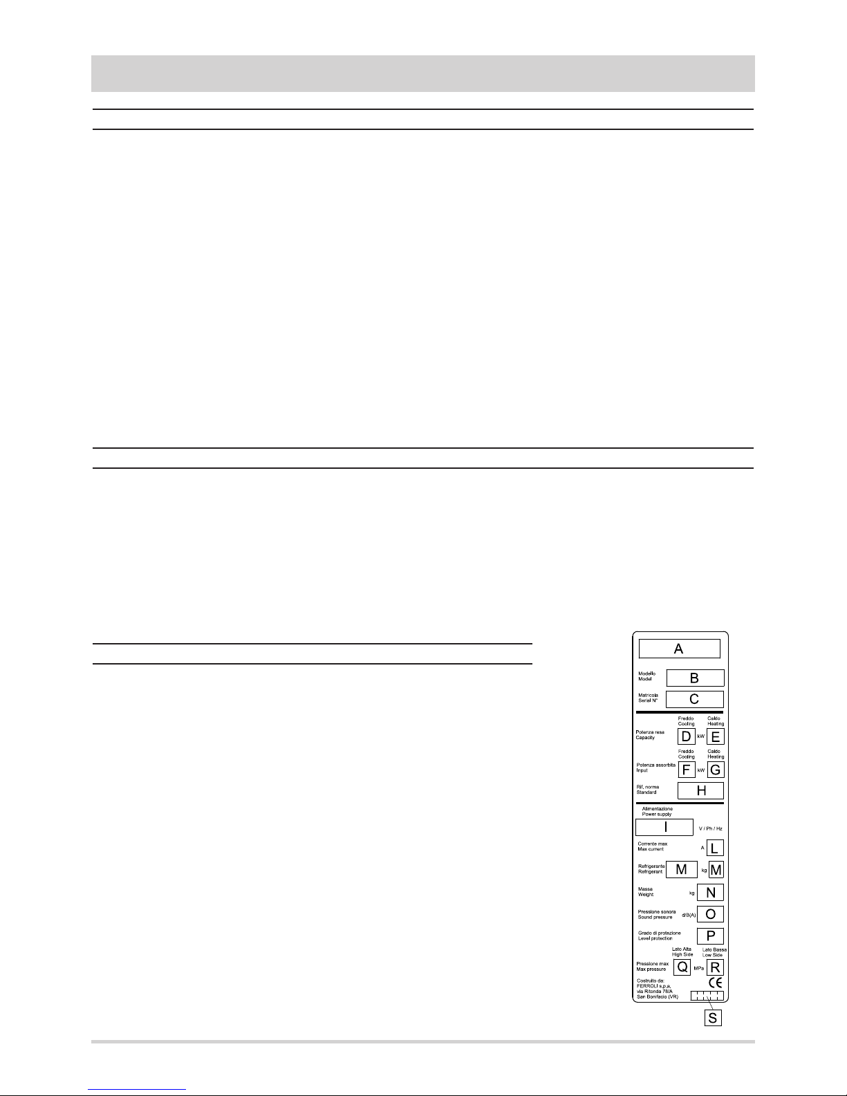
A - Trademark
B - Model
C - Serial number
D - Capacity in cooling
E - Capacity in heating (heat pump)
F - Power input in cooling
G - Power input in heating (heat pump)
H - Reference standard
I - Power supply
L - Maximum absorbed current
M - Refrigerant type and charge weight
N - Unit shipping weight
O - Sound pressure level at 1 metre
P - IP protection level
Q - Maximum pressure - high pressure side
R - Maximum pressure - low pressure side
S - PED certification body
The figure on the right shows the fields reported on the unit dataplate :
General instructions
Declaration of conformity
Unit dataplate
4
Page 5

5
Unit description
GENERAL FEATURES
Unit identification code
This series of water-water heat pumps satisfies the heating,
cooling and domestic hot water production requirements of
residential plants of small and medium size.
All the units are suitable for indoor installation and can be
applied to fan coil plants, radiant floor plants and high efficiency radiators plants.
As source both water (from well, river, lake…) or brine solutions (from geothermic probes) can be used.
The control system allows to manage not only the refrigerant
circuit but the whole plant with the possibility to choose different solutions both for the heating and cooling plant and for the
domestic hot water management. The possibility of solar
panels or other heating sources integration is also available.
The heating function optimizes the flow water temperature
according both to the ambient temperature and to the outdoor
temperature through climatic curves adaptable to the building
features. It’s possible to manage a storage tank and two independent circuits (a direct one and a mixed one).
The domestic hot water management allows to control the
three way valve, the storage tank and the anti-legionella
cycles (if necessary).
The cooling function can be realized through “passive
cooling” (free cooling) , through “active cooling” (refrigerant
circuit inversion) or through both systems actuated in sequence. When the unit is used in radiant floor plants, to avoid condensate generation, a room humidity sensor can be installed.
The internal programmer clock allows to define different
daily switching programs for heating, cooling and domestic hot
water production.
The refrigerant circuit, contained in an extractable box to sim-
plify the maintenance operations, is equipped with rotary compressor mounted on damper supports, brazed plate heat
exchangers, thermostatic expansion valve and reverse cycle
valve (for reversible units). The circuit is protected by high and
low pressure switches and flow switches on both the exchangers.
The outdoor structure and the refrigerant circuit box are both
thermally and acoustically insulated in order to create a
double wall against sound propagation and to allow the installation in domestic places.
To avoid vibration propagation towards the hydraulic circuit the
refrigerant circuit box is placed on damper supports and the
connection pipes are flexible. Moreover all the hydraulic pipes
are thermally insulated to avoid condensate generation.
All the units are accurately built and individually tested in the
factory. Only electric and hydraulic connections are required
for installation.
The codes that identify the units and the meaning of the letters used are described below.
Power supply
1 - 230V - 1 - 50 Hz
5 - 400V - 3N - 50 Hz
Refrigerant type
0 - R410A
Unit model
N° compressors
VB - Base Version
Unit version
Unit type
IH - Units suitable for
hydronic plant installation
operating as heat pumps
IP - Units suitable for
hydronic plant installation
operating as reversible heat
pumps
HSW IH 7.1 VB AB 0 M 1
Operating range
M - Medium temperature.
The unit is suitable to produce water at medium temperature
AB - Base setting up
Acoustic setting up
Page 6
GENERAL FEATURES
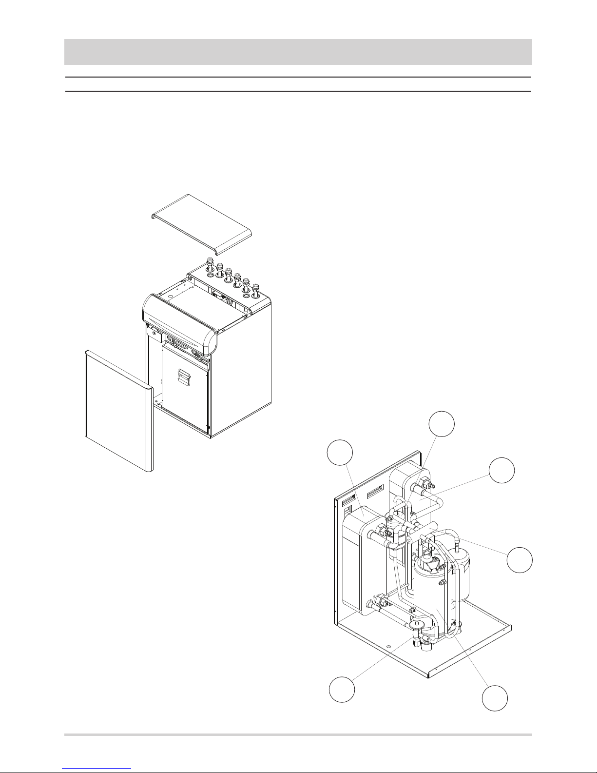
Description of components
External structure. Basement, lateral panels and frontal
panel, are completely thermally and acoustically insulated in
order to minimize thermal losses and noise emissions in the
surroundings. Accessibility to internal parts is possible removing the frontal panel and the upper panel. For extraordinary
manteinances also the rear panel can be removed.
Refrigerant circuit. It is contained inside an extractable box
to simplify the maintenance operations. The box is placed on
rubber vibration dampers and is connected to the hydraulic
circuit through flexible pipes in order to avoid the propagation
of the vibrations generated by the compressor outside the
unit. The hermetic rotary compressor (1) is mounted on dam-
per supports and is protected against overtemperatures and
overcurrents. The heat exchangers on the plant side (2) and
on the source side (3) are realized with brazed stainless steel
plates
, properly insulated to avoid condensate generation and
to minimize thermal losses, and protected by a flow switch that
detects whatever water flow lack. The expansion device (4),
a thermostatic expansion valve with external equalizer, allows
the unit to adjust itself to the different operating conditions
keeping steady the set superheating. The refrigerant circuit of
each unit contains moreover solid core hermetic filter dryer
(5) to restrain impurity and moisture residuals that could be
present in the circuit, high and low pressure switches in
order to assure the compressor to operate inside the permitted limits, 4 way reverse cycle valve (6) to allow operating
mode change reversing the refrigerant flow (only for reversible
heat pumps), pressure connections SAE 5/16” - UNF 1/2” 20 equipped with pin, gasket and blind nut, as required for the
use of R410A refrigerant (they allow the complete check of the
refrigerant circuit : compressor inlet pressure, compressor outlet pressure, thermostatic expansion valve upstream pressure
and pressure drops accross the filter). All the pipes of the refrigerant circuit are properly insulated to avoid condensate
generation and to minimize thermal losses.
Hydraulic circuit. Both the hydraulic circuit on the plant side
and on the source side are equipped with expansion vessel,
air vents and drain valves. All the pipes are thermally insulated to avoid condensate generation and minimize thermal losses. The circuit on the plant side is moreover equipped with
pressure safety valve, pressure gauge and three speed glandless pump while the water flow rate on the source side can be
adjusted by means of a three speed glandless pump or by
means of a two way valve.
Electrical panel. It contains all the power, control and security
components necessary to guarantee the unit to work properly.
The unit is managed by a microprocessor controller to
which all the electrical loads and the control devices are connected. The user interface, placed on the frontal panel of the
unit, allows to view and to modify, if necessary, all the parameters of the unit.
All the units are supplied with an outdoor temperature sen-
sor, to be installed outside, in order to realize the climatic control.
6
3
2
1
4
5
6
Page 7

7
GENERAL FEATURES
Control system
The microprocessor controller is able to manage not only the
unit itself but also all that components of the plant which allow
to realize a complete system.
The main functions of the control system are :
- room temperature control according to the outdoor tempe-
rature (climatic control)
- domestic hot water production (management of 3 way
valve, storage tank, anti legionella cycles…)
- management of a heating and/or cooling mixed circuit
(pump and 3 way mixing valve)
- management of a heating direct circuit (only pump)
- management of a storage tank for heating and/or cooling
- management of electrical heaters for heating and dome-
stic hot water (3 steps logic)
- solar panels integration
- passive cooling
- room humidity control for cooling with radiant systems
- internal programmer clock (for heating, cooling and dome-
stic hot water)
- digital input for electrical energy low tariff
- alarm memory management and diagnostic
- compressor and pump operating hour counter
- possibility to manage more units in cascade (maximum 16)
Besides the standard user interface present on all the units,
wired or wireless remote thermostats are available which
allow to control all the operating parameters of the unit and to
acquire the temperature in the different zones in order to realize a more precise and comfortable control.
The unit controller is able to manage a lot of different plant
solutions enabling automatically the necessary control
algorythms according to the components which have been
connected.
Room temperature
20.5 C
18:28
FSFS
FS
The controller is able to manage up to two zones in heating
(one by means of a mixed circuit and the other by means of a
direct circuit) and one zone in cooling (by means of a mixed
circuit).
It’s possible to realize more complex plants connecting to the
heat pump controller further expansion modules in order to
extend without limits the number of zones to be managed.
For each zone the following parameters can be set :
- set point
- daily or weekly operating time table
- climatic control curve
- room control sensor : it can be in common with the other
zones or independent (in that case it’s necessary to install
an additional room thermostat)
Page 8

GENERAL FEATURES
Options
Source side
flow rate
management
Pump Allows the circulation of the water on the source side.
2 way valve
Modulates the water flow rate on the source side when the water circulation
is assured by an external pump.
Domestic hot water
production
3 way valve
Allow to divert the hot water produced by the heat pump from the heating circuit to the domestic hot water circuit.
3 way valve with
primary heat exchanger
The hot water is diverted by the three way valve on an internal heat exchanger. An internal pump assures a correct domestic hot water flow through the
other side of the heat exchanger.
3 way valve with secondary heat exchanger
(for integrated tank)
The hot water is diverted by the three way valve in a tank integrated in the
unit (accessory). The domestic hot water is generated istantaneously by
means of an internal heat exchanger and a modulating pump.
Passive cooling
Allows to use the source to cool down the plant water without activating the
compressor.
Integrative electrical heaters
Integrate or replace the heating power supplied by the heat pump and are
managed by the unit controller with a 3 step logic.
Soft starter Reduces the compressor start current.
The controller flexibility and the big number of options available allow to get, for each model, a lot of different configura-
tions that integrate inside the heat pump many components
of the plant and allow to realize compact and tested installations.
In order to select the right configuration it is necessary to define the type of plant to which the heat pump will be connected,
both for what concerning the heating and cooling circuits, and
for what concerning the domestic hot water management.
FSFS
56
2
1
FSFS
56
2
1
FSFS
56
2
1
FSFS
56
2
1
Not reversible heat pump (IH) without options Reversible heat pump (IP) without options
Option “Source side flow rate management”
Pump 2 way valve
8
Page 9

9
GENERAL FEATURES
FSFS
56
2
1
4
3
FSFS
56
2
1
4
3
FSFS
FS
56
2
1
4
3
Option “Domestic hot water production”
3 way valve
3 way valve with primary heat exchanger
3 way valve with secondary heat exchanger
4
3
4
3
4
3
In this configuration the heat pump
can be coupled to a domestic hot
water tank equipped with a coil designed for a maximum water temperature between 55°C and 60°C.
The anti legionella cycles have to be
performed by means of electrical
heaters placed on the heat pump
outlet (see option “Integrative electrical heaters”) or directly inside the
tank.
In this configuration the heat pump
can be coupled to a domestic hot
water tank without coil.
The anti legionella cycles have to be
performed by means of electrical
heaters placed on the heat pump
outlet (see option “Integrative electrical heaters”) or directly inside the
tank.
In this configuration the heat pump
can produce instantaneously the
domestic hot water using the hot
water stored in the tank integrated in
the unit (see accessory “Domestic
hot water production tank”).
The temperature of the domestic hot
water at the unit outlet is adjusted
modulating the speed of the pump
on the primary side.
The anti legionella cycles are not
necessary.
FSFS
56
2
1
FSFS
56
2
1
Option “Passive cooling” Option “Integrative electrical heaters”
Page 10

GENERAL FEATURES
Accessories
Remote thermostat
Allows operating mode selection and set point adjustment. The on board temperature sensor can be used in
order to realize a climatic control.
Remote control
(wired or wireless)
Replicates all the control and visualization functionalities of the controller installed on the unit. The on board
temperature sensor can be used in order to realize a climatic control.
Wireless transmitter
Connected to the unit controller, allows to communicate with wireless remote control and wireless outdoor
temperature sensor.
Wireless repeater Extends wireless operating range.
Wireless adaptor for outdoor temperature sensor
Allows to transform the wired outdoor temperature sensor, standard for all the units, in a wireless sensor.
Condensate sensor In cooling mode it allows the minimum flow temperature control when condensate generation occurs.
Room hygrostat In cooling mode it allows the minimum flow temperature control according to the room humidity.
Room humidity sensor
(with or without display)
In cooling mode it allows the minimum flow temperature control according to the room dew point, calculated
from the measured room humidity.
Rubber vibration dampers
Allow to reduce the transmission to the unit support plane of the mechanical vibrations generated by the compressor and by the fans in their normal operating mode.
Transformer
230V / 24V - 3VA
It assures the correct power supply for the condensate sensor and for the room humidity sensor.
Domestic hot water
production tank
Integrated tank, to be installed under the unit, for domestic hot water production. Inside the tank a coil for solar
panels integration is contained.
Pipes for solar panels
connection
Allow to move the connections of the solar integration coil, available on the tank (accessory), directly on the
upper side of the unit.
Refrigerant circuit box If a failure occurs inside the refrigerant circuit, it permits to restart the heat pump very quickly.
10
Page 11

11
TECHNICAL DATA AND PERFORMANCES
Technical data
Frame
1
Model
3.1 5.1 7.1 9.1 11.1
U.M.
Power supply
230 - 1 - 50 230 - 1 - 50 230 - 1 - 50 230 - 1 - 50 230 - 1 - 50
V-ph-Hz
Refrigerant
Type
R410A R410A R410A R410A R410A -
Compressor
Type
rotary rotary rotary rotary rotary -
Quantity
1 1 1 1 1 n°
Power steps
0 - 100 0 - 100 0 - 100 0 - 100 0 - 100 %
Oil charge
0,35 0,43 0,67 1,13 1,13 kg
Plant side heat exchanger
Type
stainless steel
brazed plates
stainless steel
brazed plates
stainless steel
brazed plates
stainless steel
brazed plates
stainless steel
brazed plates
-
Quantity
1 1 1 1 1 n°
Water volume
0,53 0,53 0,53 0,67 0,84 l
Source side heat exchanger
Type
stainless steel
brazed plates
stainless steel
brazed plates
stainless steel
brazed plates
stainless steel
brazed plates
stainless steel
brazed plates
-
Quantity
1 1 1 1 1 n°
Water volume
0,67 0,67 0,67 0,84 1,04 l
Plant side hydraulic circuit
Safety valve set point
3 3 3 3 3 bar
Expansion vessel volume
10 10 10 10 10 l
Source side hydraulic circuit
Expansion vessel volume
10 10 10 10 10 l
Plant side pump
Type
3 speed
glandless pump
3 speed
glandless pump
3 speed
glandless pump
3 speed
glandless pump
3 speed
glandless pump
-
Quantity
1 1 1 1 1 n°
Installed power
0,14 0,14 0,14 0,14 0,14 kW
Source side pump (option)
Type
3 speed
glandless pump
3 speed
glandless pump
3 speed
glandless pump
3 speed
glandless pump
3 speed
glandless pump
-
Quantity
1 1 1 1 1 n°
Installed power
0,15 0,15 0,15 0,15 0,15 kW
Domestic hot water tank (accessory)
Volume
120 120 120 120 120 l
Solar coil surface
1,1 1,1 1,1 1,1 1,1
m
2
Integrative electrical heaters (option)
Total installed power
9,0 9,0 9,0 9,0 9,0 kW
Power steps
0 - 33 - 66 - 100 0 - 33 - 66 - 100 0 - 33 - 66 - 100 0 - 33 - 66 - 100 0 - 33 - 66 - 100
%
Page 12

TECHNICAL DATA AND PERFORMANCES
IH
Heating W10W35 ( source : water in 10°C out 7°C / plant : water in 30°C out 35°C )
Heating capacity 3,37 5,11 6,85 9,31 11,8
kW
Power input 0,59 0,90 1,24 1,69 2,18
kW
COP 5,71 5,68 5,52 5,51 5,41
-
Water flow rate plant side 578 874 1171 1591 2023
l/h
Available static head plant side 60 51 41 33 26
kPa
Water flow rate source side 798 1206 1612 2192 2781
l/h
Pressure drops source side 7 14 22 25 26
kPa
Heating B0W35 ( source : brine in 0°C out -3°C / plant : water in 30°C out 35°C )
Heating capacity 2,49 3,77 5,06 6,88 8,75
kW
Power input 0,58 0,89 1,22 1,66 2,13
kW
COP 4,29 4,24 4,15 4,14 4,11
-
Water flow rate plant side 427 646 866 1178 1497
l/h
Available static head plant side 63 58 51 46 42
kPa
Water flow rate source side 673 1018 1359 1852 2345
l/h
Pressure drops source side 5 11 17 20 21
kPa
NOMINAL performances - low temperature plants
Data declared according to EN 14511. The values are referred to units without options or accessories. Brine = water with 30% ethylene glycol.
IP
Heating W10W35 ( source : water in 10°C out 7°C / plant : water in 30°C out 35°C )
Heating capacity 3,30 5,01 6,72 9,13 11,6
kW
Power input 0,58 0,89 1,23 1,67 2,15
kW
COP 5,69 5,63 5,46 5,47 5,40
-
Water flow rate plant side 566 857 1149 1560 1989
l/h
Available static head plant side 60 52 41 34 27
kPa
Water flow rate source side 780 1181 1579 2147 2731
l/h
Pressure drops source side 6 13 21 24 25
kPa
Heating B0W35 ( source : brine in 0°C out -3°C / plant : water in 30°C out 35°C )
Heating capacity 2,44 3,70 4,97 6,74 8,60
kW
Power input 0,57 0,88 1,21 1,64 2,11
kW
COP 4,28 4,20 4,11 4,11 4,08
-
Water flow rate plant side 418 634 850 1154 1471
l/h
Available static head plant side 64 58 52 47 43
kPa
Water flow rate source side 658 997 1331 1810 2299
l/h
Pressure drops source side 5 10 17 19 20
kPa
Cooling W30W18 ( source : water in 30°C out 35°C / plant : water in 23°C out 18°C )
Cooling capacity 3,56 5,39 7,21 9,78 12,5
kW
Power input 0,59 0,90 1,24 1,68 2,17
kW
EER 6,03 5,99 5,81 5,82 5,76
-
Water flow rate plant side 611 927 1242 1686 2147
l/h
Available static head plant side 59 49 38 29 22
kPa
Water flow rate source side 710 1077 1443 1959 2498
l/h
Pressure drops source side 5 11 18 21 22
kPa
Cooling B30W18 ( source : brine in 30°C out 35°C / plant : water in 23°C out 18°C )
Cooling capacity 3,48 5,26 7,04 9,56 12,2
kW
Power input 0,60 0,93 1,27 1,73 2,23
kW
EER 5,80 5,66 5,54 5,53 5,47
-
Water flow rate plant side 598 905 1212 1647 2095
l/h
Available static head plant side 59 50 39 31 24
kPa
Water flow rate source side 828 1255 1682 2284 2911
l/h
Pressure drops source side 7 15 24 28 29
kPa
Frame
1
Model
3.1 5.1 7.1 9.1 11.1
U.M.
Power supply
230 - 1 - 50 230 - 1 - 50 230 - 1 - 50 230 - 1 - 50 230 - 1 - 50
V-ph-Hz
12
Page 13

13
TECHNICAL DATA AND PERFORMANCES
IH
Heating W10W45 ( source : water in 10°C out 7°C / plant : water in 40°C out 45°C )
Heating capacity 3,10 4,70 6,30 8,56 10,9
kW
Power input 0,71 1,08 1,48 2,01 2,58
kW
COP 4,37 4,35 4,26 4,26 4,22
-
Water flow rate plant side 529 801 1072 1458 1861
l/h
Available static head plant side 61 54 44 38 31
kPa
Water flow rate source side 686 1038 1384 1884 2401
l/h
Pressure drops source side 5 11 17 20 20
kPa
Heating B0W45 ( source : brine in 0°C out -3°C / plant : water in 40°C out 45°C )
Heating capacity 2,29 3,47 4,65 6,32 8,03
kW
Power input 0,70 1,07 1,46 1,98 2,54
kW
COP 3,27 3,24 3,18 3,19 3,16
-
Water flow rate plant side 391 592 792 1077 1369
l/h
Available static head plant side 65 60 54 50 46
kPa
Water flow rate source side 560 849 1127 1535 1944
l/h
Pressure drops source side 4 8 13 15 15
kPa
NOMINAL performances - medium temperature plants
IP
Heating W10W45 ( source : water in 10°C out 7°C / plant : water in 40°C out 45°C )
Heating capacity 3,04 4,61 6,18 8,39 10,7
kW
Power input 0,70 1,07 1,46 1,98 2,54
kW
COP 4,34 4,31 4,23 4,24 4,21
-
Water flow rate plant side 519 785 1052 1429 1827
l/h
Available static head plant side 62 54 45 39 32
kPa
Water flow rate source side 672 1015 1355 1844 2353
l/h
Pressure drops source side 5 10 16 19 20
kPa
Heating B0W45 ( source : brine in 0°C out -3°C / plant : water in 40°C out 45°C )
Heating capacity 2,24 3,40 4,57 6,20 7,90
kW
Power input 0,69 1,06 1,44 1,95 2,51
kW
COP 3,25 3,21 3,17 3,18 3,15
-
Water flow rate plant side 382 581 779 1057 1347
l/h
Available static head plant side 65 60 54 50 46
kPa
Water flow rate source side 546 828 1106 1504 1909
l/h
Pressure drops source side 3 8 12 14 15
kPa
Cooling W30W7 ( source : water in 30°C out 35°C / plant : water in 12°C out 7°C )
Cooling capacity 2,74 4,14 5,55 7,53 9,61
kW
Power input 0,59 0,91 1,24 1,68 2,16
kW
EER 4,64 4,55 4,48 4,48 4,45
-
Water flow rate plant side 470 712 954 1296 1652
l/h
Available static head plant side 62 56 48 43 37
kPa
Water flow rate source side 571 866 1161 1575 2013
l/h
Pressure drops source side 3 8 13 14 15
kPa
Cooling B30W7 ( source : brine in 30°C out 35°C / plant : water in 12°C out 7°C )
Cooling capacity 2,69 4,07 5,44 7,38 9,42
kW
Power input 0,60 0,93 1,26 1,72 2,22
kW
EER 4,48 4,38 4,32 4,29 4,24
-
Water flow rate plant side 462 698 935 1270 1620
l/h
Available static head plant side 62 56 49 43 38
kPa
Water flow rate source side 669 1015 1359 1845 2358
l/h
Pressure drops source side 5 11 17 20 21
kPa
Frame
1
Model
3.1 5.1 7.1 9.1 11.1
U.M.
Power supply
230 - 1 - 50 230 - 1 - 50 230 - 1 - 50 230 - 1 - 50 230 - 1 - 50
V-ph-Hz
Data declared according to EN 14511. The values are referred to units without options or accessories. Brine = water with 30% ethylene glycol.
Page 14

The graphs allow to get the corrective factors to be applied to
the nominal performances in order to obtain the real performances in the selected operating conditions.
The reference nominal conditions are :
- water-water units : W10W35 (source : water in 10°C out 7°C
/ plant : water in 30°C out 35°C)
- brine-water units : B0W35 (source : water in 0°C out -3°C /
plant : water in 30°C out 35°C)
TECHNICAL DATA AND PERFORMANCES
HEATING performances
Outlet temperature
plant side :
A = 55°C
B = 45°C
C = 35°C
D = 25°C
0,4
0,5
0,6
0,7
0,8
0,9
1,0
1,1
1,2
1,3
1,4
1,5
1,6
1,7
1,8
-10 -5 0 5 10 15 20 25
Heating capacity ( brine )
Inlet temperature - source side [°C]
0,4
0,5
0,6
0,7
0,8
0,9
1,0
1,1
1,2
1,3
1,4
1,5
1,6
1,7
1,8
-10 -5 0 5 10 15 20 25
Power input ( brine and water )
Inlet temperature - source side [°C]
0,4
0,6
0,8
1,0
1,2
1,4
1,6
1,8
2,0
2,2
2,4
2,6
2,8
3,0
-10 -5 0 5 10 15 20 25
COP ( brine )
Inlet temperature - source side [°C]
0,5
0,6
0,7
0,8
0,9
1,0
1,1
1,2
1,3
1,4
1,5
1,6
1,7
1,8
-10 -5 0 5 10 15 20 25
Heating capacity (water )
Inlet temperature - source side [°C]
0,4
0,6
0,8
1,0
1,2
1,4
1,6
1,8
2,0
2,2
2,4
2,6
2,8
3,0
-10 -5 0 5 10 15 20 25
COP ( water )
Inlet temperature - source side [°C]
B
C
A
D
B
C
A
D
C
B
D
A
C
B
D
A
CB DA
14
Page 15

15
TECHNICAL DATA AND PERFORMANCES
COOLING performances
0,4
0,5
0,6
0,7
0,8
0,9
1,0
1,1
1,2
1,3
1,4
1,5
1,6
1,7
1,8
-10 -5 0 5 10 15 20 25 30 35 40 45
Cooling capacity ( brine and water )
Inlet temperature - source side [°C]
0,4
0,5
0,6
0,7
0,8
0,9
1,0
1,1
1,2
1,3
1,4
1,5
1,6
1,7
1,8
-10 -5 0 5 10 15 20 25 30 35 40 45
Power input ( brine and water )
Inlet temperature - source side [°C]
0,4
0,6
0,8
1,0
1,2
1,4
1,6
1,8
2,0
2,2
2,4
2,6
2,8
3,0
-10 -5 0 5 10 15 20 25 30 35 40 45
EER ( brine and water )
Inlet temperature - source side [°C]
The graphs allow to get the corrective factors to be applied to
the nominal performances in order to obtain the real performances in the selected operating conditions.
The reference nominal conditions are :
- water-water units : W30W7 (source : water in 30°C out 35°C
/ plant : water in 12°C out 7°C)
- brine-water units : B30W7 (source : brine in 30°C out 35°C
/ plant : water in 12°C out 7°C)
Outlet temperature
plant side :
A = 24°C
B = 18°C
C = 12°C
D = 7°C
C
B
D
A
B
C
A
D
B
C
A
D
The performances of the units, when used as brine - water, are referred to applications in which the source side fluid is a solution of water and 30% ethylene glycol by volume.
Such a concentration guarantees a freezing temperature of about -15°C and allows the unit to work inside the declared operating limits.
Page 16

TECHNICAL DATA AND PERFORMANCES
Plant side hydraulic performances
0
10
20
30
40
50
60
70
80
0 500 1000 1500 2000 2500 3000 3500
Flow rate [ l/h ]
3.1
7.1
9.1
5.1
11.1
The graphs are referred to units operating with water at the temperature of 10°C (density 1000 kg/m3).
Available static head - unit without options
0
5
10
15
20
25
30
35
40
0 500 1000 1500 2000 2500 3000 3500
Flow rate [ l/h ]
A
C
B
A = unit with option “Domestic hot water production” : “3 way valve”
B = unit with option “Integrative electrical heaters”
C = unit with option “Passive cooling”
Pressure drops
16
Available static head [ kPa ]
Pressure drops [ kPa ]
Page 17

17
0
5
10
15
20
25
30
35
40
0 500 1000 1500 2000 2500 3000 3500
TECHNICAL DATA AND PERFORMANCES
Source side hydraulic performances
Flow rate [ l/h ]
Pressure drops [ kPa ]
7.1
9.1
5.1
11.1
3.1
0
10
20
30
40
50
60
70
80
0 500 1000 1500 2000 2500 3000 3500
Flow rate [ l/h ]
Available static head [ kPa ]
7.1
9.1
5.1
11.1
3.1
Pressure drops - unit without options
Available static head - unit with option “Source side flow rate management” : “Pump”
The graphs are referred to units operating with water at the temperature of 10°C (density 1000 kg/m3).
Page 18

TECHNICAL DATA AND PERFORMANCES
Domestic hot water side hydraulic performances
The graphs are referred to units operating with water at the temperature of 10°C (density 1000 kg/m3).
0
10
20
30
40
50
60
70
80
0 500 1000 1500 2000 2500 3000 3500
Flow rate [ l/h ]
A
B
A = unit with option “Domestic hot water production” : “3 way valve”
B = unit with option “Domestic hot water production” : “3 way valve with primary heat exchanger”
Available static head
0
5
10
15
20
25
30
35
40
0 500 1000 1500 2000 2500 3000 3500
Flow rate [ l/h ]
Pressure drops - unit with option “Passive cooling”
3.1
7.1
9.1
5.1
11.1
18
Pressure drops [ kPa ]Available static head [ kPa ]
Page 19

19
-5
0
5
10
15
20
25
30
35
40
45
50
55
60
65
-15 -10 -5 0 5 10 15 20 25 30 35 40 45 50
TECHNICAL DATA AND PERFORMANCES
The graphs reported below show the operating area inside which the correct working of the unit is guaranteed. The dotted lines
show the operating area when brine solutions in the source side hydraulic circuit are used.
HEATING
Inlet temperature - source side [°C]
Outlet temperature - plant side [°C]
Operating limits
-5
0
5
10
15
20
25
30
35
40
45
-15 -10 -5 0 5 10 15 20 25 30 35 40 45 50
COOLING
Inlet temperature - source side [°C]
Outlet temperature - plant side [°C]
Temperature difference between unit inlet and outlet Plant side Source side
∆T max
Maximum value 11 5
°C
∆T min
Minimum value 3 1
°C
Passive
cooling
Page 20

TECHNICAL DATA AND PERFORMANCES
Electrical data
Unit
Power supply 230 - 1 - 50 230 - 1 - 50 230 - 1 - 50 230 - 1 - 50 230 - 1 - 50
V-ph-Hz
F.L.A. Maximum total current input 5,9 7,7 10,1 13,3 17,0
A
F.L.I. Maximum total power input 1,3 1,7 2,2 2,9 3,7
kW
M.I.C.
Maximum total start current 36 45 52 82 112
A
Maximum total start current
with soft starter (option)
32 35 38 41 43
A
Integrative electrical heaters
Power supply
230 - 1 - 50 230 - 1 - 50 230 - 1 - 50 230 - 1 - 50 230 - 1 - 50
V-ph-Hz
400 - 3N - 50 400 - 3N - 50 400 - 3N - 50 400 - 3N - 50 400 - 3N - 50
F.L.A.
Maximum total current input
( 230V - 1 - 50Hz )
39,1 39,1 39,1 39,1 39,1
A
Maximum total current input
( 400V - 3N - 50Hz )
13,0 13,0 13,0 13,0 13,0
A
F.L.I. Maximum total power input 9,0 9,0 9,0 9,0 9,0
kW
Source side pump (option)
Power supply 230 - 1 - 50 230 - 1 - 50 230 - 1 - 50 230 - 1 - 50 230 - 1 - 50
V-ph-Hz
F.L.A. Maximum total current input 0,8 0,8 0,8 0,8 0,8
A
F.L.I. Maximum total power input 0,15 0,15 0,15 0,15 0,15
kW
Domestic hot water production pump (with option “3 way valve with primary heat exchanger”)
Power supply 230 - 1 - 50 230 - 1 - 50 230 - 1 - 50 230 - 1 - 50 230 - 1 - 50
V-ph-Hz
F.L.A. Maximum total current input 0,4 0,4 0,4 0,4 0,4
A
F.L.I. Maximum total power input 0,08 0,08 0,08 0,08 0,08
kW
Domestic hot water production pump (with option “3 way valve with secondary heat exchanger”)
Power supply 230 - 1 - 50 230 - 1 - 50 230 - 1 - 50 230 - 1 - 50 230 - 1 - 50
V-ph-Hz
F.L.A. Maximum total current input 0,7 0,7 0,7 0,7 0,7
A
F.L.I. Maximum total power input 0,14 0,14 0,14 0,14 0,14
kW
Noise levels
Model
Sound power levels [dB]
by octave bands [Hz]
Sound power
level
Sound pressure
level at 1 m
63 125 250 500 1000 2000 4000 8000
[dB] [dB(A)] [dB(A)]
3.1
73,2 63,3 48,3 31,7 31,0 22,6 20,9 21,9 74 51 36
5.1
74,2 64,3 49,3 32,7 32,0 23,6 21,9 22,9 75 52 37
7.1
74,2 64,3 49,3 32,7 32,0 23,6 21,9 22,9 75 52 37
9.1
75,2 65,3 50,3 33,7 33,0 24,6 22,9 23,9 76 53 38
11.1
75,2 65,3 50,3 33,7 33,0 24,6 22,9 23,9 76 53 38
Reference conditions
Performances referred to units operating in heating mode at nominal conditions W10W35.
Unit placed in free field on reflecting surface (directional factor equal to 2).
The sound power level is measured according to ISO 3744 standard.
The sound pressure level is calculated according to ISO 3744 and is referred to a distance of 1 meter from the external surface of the unit.
Frame
1
Model
3.1 5.1 7.1 9.1 11.1
U.M.
20
Page 21

21
TECHNICAL DATA AND PERFORMANCES
Weights
Unit
Unit without options 130 134 136 145 148
kg
Options
Source side flow
rate management
Pump 3 3 3 3 3
kg
2 way valve 2 2 2 2 2
kg
Domestic
hot water
production
3 way valve 3 3 3 3 3
kg
3 way valve with primary heat exchanger
9 9 9 9 9
kg
3 way valve with secondary heat exchanger
10 10 10 10 10
kg
Passive cooling 5 5 5 5 5
kg
Integrative electrical heaters 5 5 5 5 5
kg
Accessories
Domestic hot water production tank 77 77 77 77 77
kg
Pipes for solar panels connection 2 2 2 2 2
kg
Refrigerant circuit box 50 54 56 65 68
kg
Components weights
Unit
Unit without options 148 452 154 163 166
kg
Options
Source side flow
rate management
Pump 3 3 3 3 3
kg
2 way valve 2 2 2 2 2
kg
Domestic
hot water
production
3 way valve 3 3 3 3 3
kg
3 way valve with primary heat exchanger
9 9 9 9 9
kg
3 way valve with secondary heat exchanger
10 10 10 10 10
kg
Passive cooling 5 5 5 5 5
kg
Integrative electrical heaters 5 5 5 5 5
kg
Accessories
Domestic hot water production tank 95 95 95 95 95
kg
Pipes for solar panels connection 3 3 3 3 3
kg
Refrigerant circuit box 52 56 58 67 70
kg
Unit
Unit without options 133 137 139 148 152
kg
Options
Source side flow
rate management
Pump 4 4 4 4 4
kg
2 way valve 3 3 3 3 3
kg
Domestic
hot water
production
3 way valve 5 5 5 5 5
kg
3 way valve with primary heat exchanger
13 13 13 13 13
kg
3 way valve with secondary heat exchanger
14 14 14 14 14
kg
Passive cooling 8 8 8 8 8
kg
Integrative electrical heaters 6 6 6 6 6
kg
Accessories
Domestic hot water production tank 202 202 202 202 202
kg
Pipes for solar panels connection 5 5 5 5 5
kg
Transport weights
Operating weights
Frame
1
Model
3.1 5.1 7.1 9.1 11.1
U.M.
Page 22

22
TECHNICAL DATA AND PERFORMANCES
Overall dimensions
Rispect the free area around the unit as shown in figure in order
to guarantee a good accessibility and facilitate maintenance and
control operations.
852
85
53
600
600
90 80 80 80 90 90 90
A
B
A 600 mm
B 300 mm
Minimum operating area
A
B
600600
90 80 80 80 90 9090
53
93
1678 85
= =
= =
Unit with accessory
“Domestic hot water
production tank”
Unit with accessory “Domestic hot water production tank”
1 Plant return 1” M
2 Plant flow 1” M
3 Domestic hot water return 1” M
4 Domestic hot water flow 1” M
5 Source return 1” M
6 Source flow 1” M
7 Solar panel return 1” M
8 Solar panel flow 1” M
1 2 3 4 5 6
1 2 3 4 5
6
8 7
Page 23

CONNECTIONS
23
Hydraulic connections
To design properly the hydraulic system respect the local
safety regulations in force.
It is always necessary to guarantee an appropriate water flow
through the plate heat exchangers of the unit even if on both
the hydraulic circuits (source side and plant side) is installed,
as standard, a flow switch that stops the unit if the water flow
rate is too low.
To adjust the water flow rate through the heat exchangers
modify the speed of the pump by means of the 3 speed selector. For a more accurate adjustment it is reccomended the
installation of a valve on the outlet of each circuit.
It is also reccomended to install a filter on the inlet of each circuit in order to avoid the entrance of foreign substances.
The hydraulic circuit on the plant side is equipped with safety
valve and expansion vessel. To mantain the circuit under pressure a self-filling group, that automatically fills the circuit, can
be installed.
The hydraulic circuit on the source side is equipped with
expansion vessel. If it is used as a closed circuit it is necessary to install an adequate safety valve (maximum setting 6
bar).
Suggestions for the hydraulic plant realization
Prepare the pipes with the minimum possible number of
bends in order to minimize pressure losses, and suitably support them to prevent excessive stresses at the connections of
the unit.
Install shut-off valves near the components that need maintenance, to allow their replacement without having to drain the
system.
Provide manual or automatic valves in the highest part of the
circuit to vent the air.
Make sure there are no leaks before insulating the pipes and
filling the system.
In order to avoid condensate generation insulate all the pipes
on the source side (and also on the plant side for reversible
heat pumps) using steam barrier type material.
Brine solutions
When the unit is used as a brine-water heat pump, the source
side hydraulic circuit must be filled with a brine solution able to
guarantee a freezing temperature lower than the minimum
expected operating temperature. In order to guarantee the
unit to work inside the whole operating range declared, a freezing temperature not higher than -15°C is required.
The brine solution must be mixed before filling the circuit.
All the components used on the source side hydraulic circuit
must be suitable to work with the brine solution adopted.
Galvanized steel pipes are not to be used.
Expansion vessels setting
All the units are equipped with expansion vessels (source side
and plant side).
The precharge pressure of the expansion vessel must be adequate to the total volume of the hydraulic circuit at which the
unit is connected.
The factory setting (p
VE-std
= 0,5 bar g) is the minimum value
necessary to avoid the presence of zones with a negative relative pressure inside the hydraulic circuit and the risk of pump
cavitation, supposing that no parts of the plant are placed at a
higher level than the one at which the unit is installed. In that
case the precharge pressure must be increased proportionally
to the elevation of the highest part of the plant according to the
following relation :
pVE= p
VE-std
+ H
max
/ 9,81
pVE: expansion vessel precharge pressure [bar g]
H
max
elevation of the highest part of the plant referred to
the unit installation level [m]
The maximum value of the precharge pressure is equal to the
safety valve pressure set.
Increasing the precharge pressure, the maximum plant volume supported by the expansion vessel of the unit is reduced :
VI= VVE· Ce· [ 1 - ( 1 + pVE) / ( 1 + pVS) ]
VI: plant volume supported by the expansion vessel [l]
VVE: expansion vessel volume [l]
Ce: expansion coefficient
pVS: safety valve pressure set [bar g]
If the real plant volume is higher than such calculated volume,
it is necessary to install an additional expansion vessel of
appropriate volume.
Once the hydraulic circuit has been filled, the pressure at the
expansion vessel must be slightly higher than the precharge
pressure.
If parts of the plant are placed at a lower level than the one at
which the unit is installed, verify that the components can withstand the maximum pressure that can be present.
Water
Ethylene glycol
(percentage by volume)
Propylene glycol
(percentage by volume)
10% 20% 30% 40% 10% 20% 30% 40%
Freezing temperature [°C] 0 -3,8 -8,9 -15,7 -24,9 -3,4 -7,4 -13,1 -21,5
C
e
Plant side (Tmin = 5°C , Tmax = 60°C) 58,63 47,80 45,24 42,82 40,61 45,47 39,96 35,82 32,88
Source side (Tmin = 5°C , Tmax = 45°C) 101,46 73,28 68,84 64,77 61,08 69,42 60,41 53,91 49,03
Source side (Tmin = -10°C , Tmax = 45°C) - - - 51,85 48,57 - - 42,67 38,50
Page 24

CONNECTIONS
24
Electrical connections
The electrical wirings must be carried out by qualified personnel according to the regulations in force at the installation time
in the country of installation. Before starting any work on the
electrical circuit make sure that the unit power supply line is
disconnected at the start.
N.B. Refer to the electrical diagram enclosed in the unit.
Power supply system
The power cables of the heat pump power supply line must be
connected to :
- for single phase power supply : from a single phase voltage system provided with neutral conductor and separated earth wire :
V = 230 V ± 10 %
f = 50 Hz
- for three phase power supply : from a symmetrical three
phase voltage system provided with neutral conductor
and separated earth wire :
V = 400 V ± 10 %
f = 50 Hz
The units are shipped completely factory wired and arranged
for the connection to the power supply.
The power cables must enter the unit through the holes on the
rear panel and must be connected to the power supply terminals of the unit.
The integrative electrical heaters (option) must be supplied by
a dedicated power supply line to be connected to the power
supply terminals inside the electrical board of the unit.
Heat pump power supply
The power supply cables must have an adequate section for
the power absorbed by the unit and must be chosen in conformity with the regulations in force. Design the power supply
line, always referring to the total FLI and FLA values of the
unit, taking into account the selected options (except the integrative electrical heaters) and the installed accessories.
Integrative electrical heaters power supply
The power supply cables must have an adequate section for
the power absorbed by the only integrative electrical heaters
and must be chosen in conformity with the regulations in force.
It is possible to connect the integrative electrical heaters either
to a single phase power supply or to a three phase power
supply.
If a three phase power supply is used, connecting to the terminal R the same phase used to supply the heat pump, the
maximum absorbed current for each phase never exceeds
16A.
Upstream protection
An automatic switch suitable for ensuring protection against
overcurrents and indirect contacts must be installed upstream
each power supply line.
Coordination between line switch must be carried out observing the regulations in force on electrical safety, regarding the
type of installation and the installation ambient conditions.
Connection available for the user
The electrical board of the heat pump contains some terminals
dedicated to the connection of temperature probes, humidity
probes, pumps, valves ...
Carry out all the necessary connections in order to realize the
desired plant following the instructions reported in the section
“Inputs and outputs”.
ATTENTION
Carry out all the connections outside the heat pump avoiding
the power cables and the probe cables to be coupled.
N1 R S T L N PE
N L L N PE
N1 R S T L N PE
N L1 L2 L3 L1 N PE
Heat pump
Integrative
electrical heaters
Heat pump
Integrative
electrical heaters
Integrative electrical heaters connection
with three phase power supply
Integrative electrical heaters connection
with single phase power supply
Page 25

RECEIVING AND POSITIONING
25
Receiving
Positioning
Check on receiving
As soon as the unit is received verify accurately the correspondance of the load to what was ordered to make sure that
all the material has been delivered. Check carefully that the
load has not been damaged. In case of goods with visible
damages inform promptly the haulage contractor reporting on
the delivery note the phrase “Collected with reserves owing
to evident damage”. Delivery ex works implies reimbursement of any damage on charge of the insurance company as
established by law.
Safety instructions
Observe the safety regulations in force concerning the equipment to use for unit handling or the operating formalities to follow.
Handling
Before handling the unit, check the weight of the unit , reported both on the dataplate and on the technical documentation.
Make sure the unit to be handled with care avoiding any kind
of collision that could damage the operating parts of the unit.
On the packaging of the unit are reported all the instructions
necessary for a corect handling during storing and installation.
The unit is supplied on a pallet suitable for the transport. It is
advisable to place protective material between the truck and
the unit to avoid damages to the unit. Prevent the unit or parts
of it from falling down.
Storing
The units must be stored in a dry place, repaired from sun,
rain, sand or wind.
Do not stack the units.
Maximum temperature = 60 °C
Minimum temperature = -20 °C
Humidity = 90 %
Packaging removal
Remove the packaging taking care not to damage the unit.
Check for any visible damage.
Get rid of the packaging material sending them to specialized recycling centres (observe the regulations in force).
The units are suitable for indoor installation.
Verify that the support surface can bear the weight of the
selected unit and is perfectly horizontal. In order to limit the
vibrations transmitted by the unit it is possible to place, between the unit base and the support surface, a strip of hard
rubber or, if a higher level of insulation is required, vibration
dampers.
In any case it is not advisable to place the unit near private
offices, bedrooms or zones where very low noise levels are
required.
Respect the minimum operating area and verify that the installation place is not subject to flooding.
Page 26

START UP
26
Start up
The following operations must be carried out only by properly trained personnel. To make the contractual warranty effective,
start up must be carried out by authorized service centres.
Before calling the service centre it is advisable to make sure that all the installation steps have been completed (positioning, electrical connections, hydraulic connections).
Preliminary checks before turning on
1. Verify that :
- the unit has not suffered visible damages due to transport or positioning
- the unit is placed on an horizontal surface able to bear its weight
- the minimum operating area are respected
- tha ambient conditions comply with the provided operating limits
- the hydraulic and electrical connections has been carried out correctly
2. Disconnect the unit power suply line at the start and make sure that :
- the unit power supply line complies with the regulations in force
- the screws, fastening the electrical cables to the components inside the electrical panel of the unit, are well tightened (vibra-
tions during transport phases could have caused some loosening)
3. Connect the unit power supply line and verify that :
- the voltage of the power supply line complies with the the nominal one of the unit
- for three phase power supply units, the unbalance between the phases is lower than 2% (a higher value produces an exce-
sive current input on one or more phases causing possible damages to the electrical components of the unit)
NOTE. Example of phase unbalance calculation
- Read the value of the three line voltages using a voltmeter :
line voltage between phases L1and L2: V
1-2
= 390 V
line voltage between phases L2and L3: V
2-3
= 397 V
line voltage between phases L3and L1: V
3-1
= 395 V
- Calculate the difference between the maximum and minimum value of the measured line voltages :
∆V
max
= max ( V
1-2
; V
2-3
; V
3-1
) - min ( V
1-2
; V
2-3
; V
3-1
) = V
2-3
- V
1-2
= 397 - 390 = 7 V
- Calculate the average line voltage value :
V
average
= ( V
1-2
+ V
2-3
+ V
3-1
) / 3 = ( 390 + 397 + 395 ) / 3 = 394 V
- Calculate the percentage unbalance value :
∆V
max
/ V
average
x 100 = 7 / 394 x 100 = 1,78 % < 2 %
Turning on
Press the unit switch on button placed on the frontal panel of the unit.
Start all the plant components necessary to guarantee an adequate water flow rate on the source hydraulic circuit (only if the
source side pump is not present).
Set the type of heat pump (water-water or brine-water) modifying the parameter 5800.
Activate the unit in heating or in cooling mode operating on the user interface or on the remote controls and insert a set point
suitable to require the unit to work.
Page 27

CONTROL SYSTEM
27
Control system configuration
The control system can be configured in different ways in order
to adapt itself to the user needs and to the kind of plant managed by the heat pump.
The simpler configuration consists of unit controller (A), outdoor
air temperature sensor (B) and user interface (C). Such components are always supplied with the unit and allow to realize a climatic control based only on the outdoor air temperature.
Starting from this configuration it is possible to add, as accessories, remote thermostats (D) or remote controls (E) in order to
realize a climatic control based also on the room temperature of each zone and to control the heat pump at a distance.
The communication between the devices of the control system can be carried out through wired or wireless connections. To realize a wireless network are available, as accessories : wireless transmitter (F) to be connected to the heat pump controller, wireless adaptor for outdoor temperature sensor (G) , wireless remote control (H) and wireless repeater (I) to be used to amplify the
signal when the distance between the devices is large.
B
T
C
A
B
T
EDC
A
B
T
HC
F
H
I
G
A
Page 28

CONTROL SYSTEM
28
Heating and cooling circuits
The controller of the heat pump is able to manage two circuits in HEATING and one circuit in COOLING.
The management of further heating or cooling circuits, possible by means of additional expansion modules, is not treated in this
manual.
Function Circuit name Type of circuit
Heating
HC1 Heating circuit 1 mixed
HCP Heating circuit P direct (unmixed)
Cooling CC1 Cooling circuit 1 mixed
The heating circuit 1 and the cooling circuit 1 control the same plant components (pump and mixing valve). For the mixing valve
management a temperature sensor (probe B1) on the flow of the circuit must be install.
By means of these three circuits it is possible to manage up to two zones :
Zone 1 : heating through heating circuit 1
cooling through cooling circuit 1
Zone 2 : heating through heating circuit P
cooling not managed
The heating circuit P can also be managed together with the heating circuit 1, sharing set point and room temperature sensor.
In that case zone 2 is not present. Heating circuit P management is defined by parameter 46 set on the user interface of the unit.
For each zone can be set :
- set point
- daily or weekly operating time table
- climatic curve
- room control sensor
The room sensor of each zone is contained inside the remote thermostat or the remote control. For each zone it is possible to
install a remote control or a remote thermostat (it is not possible to install both). Each zone can operate also without room sensor (in that case the climatic control is based only on the outdoor air temperature).
If a remote thermostat or a remote control is present, the management of each zone is always possible also through the unit user
interface.
The diagrams reported below show the different possible configurations of the system and the parameters to be set.
User interface
46 HCP management independent
User interface
46 HCP management together with HC1
Zone 1
HC1/CC1 HCP
Zone 1 Zone 2
HC1/CC1 HCP
Configuration 1
Zone 1 : management through user interface
Zone 2 : not present
Configuration 2
Zone 1 : management through user interface
Zone 2 : management through user interface
Page 29

CONTROL SYSTEM
29
Remote
control 1
Remote
thermostat 1
Remote
control 2
Remote
thermostat 2
Zone 1 Zone 2
HC1/CC1 HCP
Remote
control 1
Remote
thermostat 1
Zone 1 Zone 2
HC1/CC1 HCP
Remote
control 1
Zone 1
HC1/CC1 HCP
Remote
control 1
Remote
thermostat 1
Zone 1 Zone 2
HC1/CC1 HCP
Configuration 3
Zone 1 : management through remote control
Zone 2 : not present
Configuration 5
Zone 1 : management through user interface
Zone 2 : management through remote control or thermostat
User interface
46 HCP management together with HC1
Remote control 1
40 Room unit 1
42 HC1 + HCP
46 HCP management together with HC1
48 HC1
User interface
46 HCP management independent
Remote control 1
40 Room unit P
42 -
Remote thermostat 1
ru 3
User interface
46 HCP management independent
Remote control 1
40 Room unit 1
42 HC1
Remote thermostat 1
ru 1
User interface
46 HCP management independent
Remote control 1
40 Room unit 1
42 HC1
Remote thermostat 1
ru 1
Remote control 2
40 Room unit P
42 -
Remote thermostat 2
ru 3
Configuration 4
Zone 1 : management through remote control or thermostat
Zone 2 : management through user interface
Configuration 6
Zone 1 : management through remote control or thermostat
Zone 2 : management through remote control or thermostat
Page 30

CONTROL SYSTEM
30
Control system devices installation
They should be located in the main room of the zone they manage
taking into account the following criteria :
- the place of installation should be chosen so that the sensor can
measure the room temperature as accurately as possible without
being influenced by the direct solar radiation or by other hot or cold
sources (about 1,5 meters above the floor);
- in the case of wall mounting, enough clearance above the device
must remain, enabling it to be fitted and removed.
REMOTE THERMOSTAT AND REMOTE CONTROL ( WIRED OR WIRELESS )
The power supply of the remote thermostat and of the remote control is supplied by the mounting base. When the devices are
removed from their base, power is cut off and the devices are out of operation. The wireless remote control is powered by three
1,5 V alkaline batteries type AA (LR06).
96
9
6
9
1
4
7
1 2
4,2
65
0
6
56
60
min.
10 cm
Remote thermostat
42
5 8
1
0 0
1
82
4,2
9
56
60
001
80
1
1
9
3
7
6
Remote control
1 CL+ BSB data
2 CL- BSB ground
3 G+ Power supply
1 CL+ BSB data
2 CL- BSB ground
Wired
Wireless
Page 31

CONTROL SYSTEM
The device must be installed outside the building. The sensor is
connected to the controller of the unit or to the wireless adaptor
through a two wire cable ( the wires are interchangeable ).
OUTDOOR AIR SENSOR
The device must be installed inside the building. The device is
powered by two 1,5 V alkaline batteries type AAA (LR03). The
outdoor air sensor is connected to the adaptor through a two
wire cable ( the wires are interchangeable ).
The transmitter must be connected to the X60 terminal of the heat
pump controller. Before connecting the transmitter, the controller
must be disconnected from power.
Do NOT install the transmitter inside metal casing.
WIRELESS TRANSMITTER
The device must be installed inside the building. The device is powered through the mounting base by the power pack supplied
with the device ( the wires are interchangeable ).
WIRELESS REPEATER
28,8
43
71
66,5
55,8
A
B
C
A LED
B Button
C Terminal X60
90
001
32
12
4,2
65
0
6
56
60
B
A
A LED
B Button
90
001
32
12
4,2
65
0
6
56
60
AAA
AAA
B
A
A LED
B Button
79,8
6,19
49,7
3
5,5
Ø 14,1
2524,5
49,5
4
5,5
6
H
H
2
/
1
N
N-W
3
m
5,2
n
i
m
1
2
4
31
WIRELESS ADAPTOR FOR OUTDOOR TEMPERATURE SENSOR
Page 32

CONTROL SYSTEM
32
The wireless devices should be located in such a way that the
transmission is as interference free as possible. The following
criteria must be observed :
- do not place the devices in the vicinity of electrical cables,
strong magnetic fields or equipments as PC, televisions,
micro wave ovens...
- do not place the devices near large metal structures or con-
structional elements with fine meshes as special glass or
special concrete;
- the distance of the devices from the transmitter should not
exceed 30 meters or 2 floors.
In order to fulfill the connection two stages are necessary.
Connection establishment : wireless devices are connected
to the controller of the heat pump. This stage must be done
before installing the devices so that all the parts are within
easy reach.
Connection test : the signal quality is checked. The devices
must be already installed in their final position. If the test fails
it’s necessary to modify the position of the devices or to add a
wireless repeater in order to extend wireless operating range.
Connection establishment
Verify if the wireless transmitter is connected to the heat pump
controller and that the controller is powered.
Verify if the batteries of the wireless remote controller are properly installed.
Press the button on the wireless transmitter for at least 8
seconds. The led starts blinking at high frequency.
Press the OK button on the wireless remote controller to enter
the menu PROGRAMMING.
Press the INFO button for at least 3 seconds, select the operating level COMMISSIONING and press OK.
Select the menu WIRELESS and press OK.
Set the parameter 40 “USED AS” according to the use of the
component and press OK.
Select YES with the knob and press OK.
The process of opening the connection is started. The display
shows the progress of opening the connection in %. The process can take 2 to 120 seconds.
The connection is established when “DEVICE READY”
appears and the led on the wireless transmitter extinguishes.
Connection test
Press the OK button on the wireless remote controller to enter
the menu PROGRAMMING.
Press the INFO button for at least 3 seconds, select the operating level COMMISSIONING and press OK.
Select the menu WIRELESS and press OK.
Set the parameter 121 “TEST MODE” as ON and press OK.
The digits on the left show the telegrams sent, the digits on the
right the telegrams received. The test will be ended after 24
telegrams. The test is considered successful when at least
50% of the telegrams sent have been received.
WIRELESS REMOTE CONTROLLER
Wireless devices connection
Connection establishment
Verify if the wireless transmitter is connected to the heat pump
controller and that the controller is powered.
Verify if the batteries of the wireless adaptor are properly
installed.
Press the button on the wireless transmitter for at least 8
seconds. The led starts blinking at high frequency.
Press the button on the wireless adaptor for at least 8
seconds. Also the led on the adaptor starts blinking at high frequency.
The connection is established when the led on the wireless
transmitter extinguishes.
Press briefly the button on the wireless adaptor until also the
led on the wireless adaptor extinguishes.
Connection test
Press the button on the wireless adaptor for a maximum of 8
seconds. The led on the adaptor starts blinking at low frequency.
If the connection works correctly the led on the wireless transmitter flashes briefly at 10 second intervals.
After the test press briefly the button on the wireless adaptor
until the led on the adaptor extinguishes.
The test can be aborted pressing the ESC button
WIRELESS ADAPTOR FOR OUTDOOR TEMPERATURE SENSOR
Connection establishment
Verify if the wireless transmitter is connected to the heat pump
controller and that the controller is powered.
Verify if the wireless repeater is properly powered.
Press the button on the wireless transmitter for at least 8
seconds. The led starts blinking at high frequency.
Press the button on the wireless repeater until also the led on
the repeater starts blinking at high frequency.
The connection is established when the led on the wireless
transmitter extinguishes.
Press briefly the button on the wireless repeater until also the
led on the wireless repeater extinguishes.
Connection test
Press the button on the wireless repeater for a maximum of 8
seconds. The led on the repeater starts blinking at low frequency.
If the connection works correctly the led on the wireless transmitter flashes briefly at 10 second intervals.
After the test press briefly the button on the wireless repeater
until the led on the repeater extinguishes.
The test can be aborted pressing the ESC button
WIRELESS REPEATER
Page 33

CONTROL SYSTEM
Control system using
The user interface, placed on the frontal panel, allows the
complete control of the system permitting to visualize and
modify all the operating parameters of the unit.
The remote control (wired or wireless) replicates all the functions available through the user interface. The only differences
compared to the user interface are the presence of a tempe-
rature sensor to measure the room temperature of the zone
managed by the remote control and the replacement of the
“Reset” button with the “Occupancy” button.
The remote thermostat contains a temperature sensor to measure the room temperature but allows the access to a limited
number of functions.
Room temperature
20.5 C
18:28
INFO button
RESET button
HEATING button
ESC button
COOLING buttonKNOB
OK button
DHW button
BSB port
Room temperature
20.5 C
18:28
INFO button
OCCUPANCY button
HEATING button
ESC button
COOLING button
KNOB
OK button
DHW button
20.5 C
HEATING button
OCCUPANCY button
KNOB
33
Page 34

CONTROL SYSTEM
34
Xxxxxxxxxxxxxxxxxxxxxxxxxxx
Xxxxxxxxxxxxxxxxxxxxxxxxxxx
Xxxxxxxxxxxxxxxxxxxxxxxxxxx
Heating : Comfort set point
Heating : Reduced set point
Heating : Frost Protection set point
Cooling : Comfort set point
Wait
Change batteries
Holiday function active
Reference to heating circuit
Alarm messages
Maintenance messages
Info level
Programming level
ECO functions active
USER INTERFACE AND REMOTE CONTROL DISPLAY
REMOTE THERMOSTAT DISPLAY
HEATING button
Allows to select the active heating mode (indicated by a bar under the corresponding symbol).
Heating mode Automatic
- room temperature controlled according to the set time table (switching between Comfort and Reduced set point)
- protective functions active
- ECO functions active (automatic summer/winter changeover and automatic 24 hour heating limit)
Heating mode Comfort
- room temperature controlled according to Comfort set point
- protective functions active
- ECO functions not active (automatic summer/winter changeover and automatic 24 hour heating limit)
Heating mode Frost Protection
- room temperature controlled according to Frost Protection set point
- protective functions active
- ECO functions active (automatic summer/winter changeover and automatic 24 hour heating limit)
Heating mode Reduced
- room temperature controlled according to Reduced set point
- protective functions active
- ECO functions active (automatic summer/winter changeover and automatic 24 hour heating limit)
COOLING button
Allows to select the cooling mode (indicated by a bar under the corresponding symbol).
Cooling mode Automatic
- room temperature controlled according to the set time table (switching between Comfort set point and OFF)
- protective functions active
- cooling enabled according to the outdoor temperature
Cooling mode OFF
- protective functions active
Page 35

CONTROL SYSTEM
KNOB
Allows to modify the Comfort set point (in heating or in cooling according to the active operating mode). Press the OK
button to confirm.
Allows moreover to select the different parameters inside the menu and to select the values of each parameter.
INFO button
Pressing the INFO button various informations about the operating status of the system can be displayed. The list of
informations changes according to the type of unit, the plant configuration and the active operating mode.
When error or maintenance messages are displayed, pressing the INFO button further details about the event are provided.
DHW button
Allows to select the domestic hot water heating mode (indicated by a bar under the corresponding symbol).
RESET button
Allows to cancel pending error messages and to ignore the scheduled delays at the unit switch on avoiding undesired
waiting times during commissioning or fault tracing. This function should NOT be used in normal operation.
OCCUPANCY button
When a room is not used for a short period of time, pressing the OCCUPANCY button is possible to lower the room temperature in order to save energy. When the room is occupied again, pressing again the OCCUPANCY button, normal
operation is restored.
The function is active only in automatic heating mode or in automatic cooling mode :
- in heating : changeover from Comfort heating to Reduced heating
- in cooling : changeover from Comfort cooling to cooling OFF
The function remains active until the next operating mode change set through the time table program.
Domestic hot water heating mode ON
- domestic hot water temperature controlled according to the set time table
- protective functions active
Domestic hot water heating mode OFF
- protective functions active
Domestic hot water heating mode FORCED
Pressing for at least 3 seconds the DHW button the domestic hot water tank forced charging function is activated.
35
ECO FUNCTIONS
Automatic summer/winter changeover
This function is used to switch on or off the heating mode in the course of the year according to the outdoor air temperature. It
is possible to extend or to shorten the period of time during which the heating mode is active modifying the threshold of the outdoor air temperature at which the changeover takes place.
The threshold set is independent for each circuit (parameter 730 for heating circuit 1, parameter 1330 for heating circuit P).
Increasing the threshold the heating mode will be switched on earlier and switched off later. To take into account the building
thermal inertia the outdoor temperature is attenauted.
Automatic 24 hour heating limit
This function is used to switch on or off the heating mode in the course of the day according to the outdoor air temperature. This
function allows, in the intermediate seasons (spring and autumn), to respond to sudden changes of the outdoor air temperature.
It is possible to extend or to shorten the period of time during which the heating mode is active modifying the temperature threshold at which the changeover takes place. The threshold is calculated adding to the Comfort set point a differential. The differential set is independent for each circuit (parameter 732 for heating circuit 1, parameter 1332 for heating circuit P). Increasing
the differential the heating mode will be switched on earlier and switched off later.
To take into account the building thermal inertia the outdoor temperature is attenauted.
Page 36

CONTROL SYSTEM
36
Control system programming
The settings that can not be modified directly through the buttons of the user interface and of the remote controls are accessible through the programming parameters, grouped inside the various programming menus. The menus concerning functions
which are not active are automatically hidden.
It is possible to enter the programming menus with different user names. Each user has different authorizations concerning the
possibility to visualize and modify the parameters :
- End user E
- Commissioning I
- Heating engineer F
The programming menus are accessible only through the user interface and the remote control.
To enter the programming menus :
- return to the main display (from whatever position press repeatedly the ESC button)
- press the OK button
- press the INFO button for at least 3 seconds
- select the user name with the knob and press the OK button
- select the desired menu and press OK
To modify the parameters inside the menus :
- select the desired parameter with the knob
- press the OK button to modify the parameter
- select the new value with the knob
- press the OK button to confirm the new value or the ESC button to cancel
Menu structure
Menu Level Parameter Function
Hour and date
E 1 Hour / minutes
E 2 Day / Month
E 3 Year
Operator section E 20 Language
Time table 1
Heating circuit 1
E 500 Preselection
E 501 Phase 1 on
E 502 Phase 1 off
E 503 Phase 2 on
E 504 Phase 2 off
E 505 Phase 3 on
E 506 Phase 3 off
E 516 Default values
Time table 3
Heating circuit P
E 540 Preselection
E 541 Phase 1 on
E 542 Phase 1 off
E 543 Phase 2 on
E 544 Phase 2 off
E 545 Phase 3 on
E 546 Phase 3 off
E 556 Default values
Time table 4
Domestic hot water
E 560 Preselection
E 561 Phase 1 on
E 562 Phase 1 off
E 563 Phase 2 on
E 564 Phase 2 off
E 565 Phase 3 on
E 566 Phase 3 off
E 576 Default values
Page 37

CONTROL SYSTEM
Menu Level Parameter Function
Time table 5
Cooling circuit 1
E 600 Preselection
E 601 Phase 1 on
E 602 Phase 1 off
E 603 Phase 2 on
E 604 Phase 2 off
E 605 Phase 3 on
E 606 Phase 3 off
E 616 Default values
Holidays program
Heating circuit 1
E 642 Start
E 643 End
E 648 Operating level
Holidays program
Heating circuit P
E 662 Start
E 663 End
E 668 Operating level
Heating circuit 1
E 710 Comfort set point
E 712 Reduced set point
E 714 Frost Protection set point
E 720 Climatic curve slope
E 730 Summer/winter changeover temperature
Cooling circuit 1
E 901 Operating mode
E 902 Comfort set point
E 907 Release
Heating circuit P
E 1300 Operating mode
E 1310 Comfort set point
E 1312 Reduced set point
E 1314 Frost Protection set point
E 1320 Climatic curve slope
E 1330 Summer/winter changeover temperature
Domestic hot water
E 1610 Nominal set point
E 1612 Reduced set point
Service
Special operations
E 7120 Economy mode
E 7141 Emergency operation
Diagnostic
heat source
E 8410 Heat pump return temperature
E 8411 Set point heat pump return temperature
E 8412 Heat pump flow temperature
E 8427 Source return temperature
E 8429 Source flow temperature
Diagnostic
consumers
E 8700 Outdoor temperature
E 8701 Minimum outdoor temperature
E 8702 Maximum outdoor temperature
E 8740 Room temperature heating circuit 1
E 8741 Set point room temperature heating circuit 1
E 8743 Flow temperature heating circuit 1
E 8744 Set point flow temperature heating circuit 1
E 8756 Flow temperature cooling circuit 1
E 8757 Set point flow temperature cooling circuit 1
E 8800 Room temperature heating circuit P
E 8801 Set point room temperature heating circuit P
E 8803 Set point flow temperature heating circuit P
E 8830 Temperature 1 Domestic Hot Water
E 8831 Set point Domestic Hot Water temperature
E 8980 Temperature 1 Buffer
E 8981 Set point Buffer temperature
E 8982 Temperature 2 Buffer
E 9031 Relay output QX1
E 9032 Relay output QX2
E 9033 Relay output QX3
E 9034 Relay output QX4
E 9035 Relay output QX5
E 9036 Relay output QX6
37
Page 38

CONTROL SYSTEM
38
Remote thermostat programming
The configuration parameters of the remote thermostat must be set on the device itself.
A long press (longer than 3 seconds) on the
OCCUPANCY button allows to enter the
Programming menu from which is possible to
modify the parameters listed in the table.
When a parameter is selected the current value
blinks. Use the knob to adjust the value of the
parameter. Press briefly the OCCUPANCY button
to select the following parameter.
Press the HEATING button to escape from the
Programming menu.
Remote control (wired o wireless) programming
The configuration parameters of the remote control must be set on the device itself. Entering the “Operator section” menu it is
possible to adjust the parameters listed in the table.
Menu Level Parameter Function
Operator section
E 20 Language
F 22 Informations
F 26 Operation lock
F 27 Programming lock
I 28 Save settings
I 40 Renote control use
I 42 Heating circuits assignment
I 46 Operation heating circuit P
I 48 Action OCCUPANCY button
F 54 Room temperature sensor offset
Parameter Function
ru
Remote thermostat use
ru = 1 management heating circuit 1
ru = 3 management heating circuit P
P1
Save settings
P1 = 1 save pressing HEATING button or without confirmation
(for timeout)
P1 = 2 save pressing HEATING button
P2
Operation lock
P2 = 0 lock disabled
P2 = 1 all the buttons are locked (access to Programming
menu granted)
For details on the settings of parameters 40, 42, 44 and 46 see paragraph “Heating and cooling circuits”.
The room temperature sensor contained inside the remote control can be calibrated adding an offset (parmeter 54) to the value
read.
Functions available for the user
Heat pump type setting
It is possible to set the type of heat pump (water-water or brine-water) modifying the parameter 5800.
Hour, date and language setting
In order to set hour and date enter the “Hour and date” menu and modify the parameters 1, 2 and 3. It is possible to select the
desired language for the user interface and for each remote control through the “Operator section” menu (parameter 20).
Time tables setting
When the selected operating mode is “Automatic”, the circuits are activated according to the set time tables.
It is possible to set the time table independently for each circuit (heating circuit 1, heating circuit P, domestic hot water circuit,
cooling circuit 1).
For the cooling circuit 1 it is possible to select, through the parameter 907, whether :
- keep the circuit always activated (24 hour per day)
- activate the circuit according to time table 5
- activate the circuit according to heating circuit 1 time table
For each time table it is possible to specify the program to use in the different days of the week :
- daily (a different program for each day of the week)
- weekly (same program for all the days of the week)
- week end (a program from Monday to Friday and another program from Saturday to Sunday)
For each program it is possible to specify 3 different operating phases per day (6 switch on or switch off events per day).
All the programs can be restored to the dafault values.
Page 39

39
CONTROL SYSTEM
Operating mode selection for heating and cooling circuits
Heating circuit 1 : through the Heating button
Heating circuit P : through the Heating button (if the management of the heating circuit 1 and P is in common)
or through the parameter 1300 (if the management is independent)
Cooling circuit 1 : through the Cooling button o through the parameter 901
0 2 4 6 8 10 12 14 16 18 20 22 °C
Set point setting
For each heating circuit 3 set points can be set : Comfort, Reduced and Frost Protecion.
For each cooling circuit only one set point can be set : Comfort.
The set points of the heating circuits are related one each other : the Comfort set point can not be lower than the Reduced set
point, the Reduced set point can not be lower than the Frost Protection set point and the Frost Protection set point can not be
lower than 4°C.
Comfort
Reduced
Frost Protection
Heating circuits climatic curves setting
The climatic curves allow to calculate the flow temperature set point of each circuit according to the outdoor air temperature in
order to keep the room temperature as near as possible to the set value.
The curves are referred to a room set point of 20°C .
If the set point is modified, the curve automatically
change to adapt themselves to the new value.
It is possible to modify the parameters of the climatic
curves in order to fit the features of the plant and of
the building.
The higher the slope of the curve, the higher is the
change of the flow temperature set point for low
values of the outdoor air temperature.
If the room temperature is correct for high outdoor air
temperature but is lower than the set point for low
outdoor air temperature, the slope of the curve must
be increased and vice versa.
If on the other hand the room temperature is always
lower or higher than the set point the curve must be
translated without modifying its slope.
20 10 0 -10 -20
-30
90
80
70
60
50
40
30
°C
°C
4
3,5
3
2,75 2,5 2,25
2
1,75
1,5
1,25
1
0,75
0,5
0,25
100
Heating circuit 1 Heating circuit P Cooling circuit 1
Comfort set point parameter 710 parameter 1310 parameter 902
Reduced set point parameter 712 parameter 1312 -
Frost Protection set point parameter 714 parameter 1314 Maximum Comfort set point parameter 716 parameter 1316 40 °C
Minimum Comfort set point - - 15 °C
All the set points can be adjusted through the parameters.
The Comfort set points of the heating circuit 1 and of the cooling circuit 1 can also be adjusted by means of the knob of the user
interface.
The Comfort set point of each circuit can also be adjusted by means of the knob of the remote control or of the remote thermostat assigned to that circuit (if present).
Heating circuit 1 Heating circuit P
Climatic curve slope parameter 720 parameter 1320
Climatic curve displacement parameter 721 parameter 1321
Holidays setting
It is possible to set a holidays period for the heating circuit 1 and for the heating circuit P.
For each period it is possible to specify the start and the end date and the set point to be adopted during the holidays period.
Page 40

40
CONTROL SYSTEM
Inputs and outputs
ID Use Description Features
Available
for the user
Inputs
B9 B9
outdoor air temperature temperature sensor NTC 1K
B91 B91
source heat exchanger inlet temperature temperature sensor NTC 10K
B92 B92
source heat exchanger outlet temperature temperature sensor NTC 10K
B71 B71
plant heat exchanger inlet temperature temperature sensor NTC 10K
B21 B21
plant heat exchanger outlet temperature temperature sensor NTC 10K
B3 B3
domestic hot water buffer temperature temperature sensor NTC 10K
B1 B1
heating circuit 1 flow temperature temperature sensor NTC 10K
BX1 B4
plant buffer temperature temperature sensor NTC 10K
x
BX2 B41
plant buffer temperature - bottom temperature sensor NTC 10K
x
BX3 B31
domestic hot water buffer temperature - bottom temperature sensor NTC 10K
x (1)
BX4 B38
instantaneous domestic hot water flow temperature temperature sensor NTC 10K
x (1)
BX5 B6
solar collector temperature temperature sensor NTC 10K
x
H1 H1
instantaneous domestic hot water flow switch voltage free digital input
H3 H3
room humidity sensor
voltage free digital input
0-10 Vdc input
x
E9 E9
Low pressure switch 230 Vac digital input
E10 E10
High pressure switch 230 Vac digital input
EX1 E15
Source flow switch 230 Vac digital input
EX2 E24
Plant flow switch 230 Vac digital input
EX3 E5
Low tariff 230 Vac digital input
x
EX4 E6
Electrical power supply lock 230 Vac digital input
x
EX5 -
- 230 Vac digital input
x
EX6 -
- 230 Vac digital input
x
EX7 -
- 230 Vac digital input
x
Outputs
K1 K1
Compressor 2 A - 230 Vac
Q2 Q2
Heating circuit 1 pump 2 A - 230 Vac
Q3 Q3
Domestic hot water 3 way valve 2 A - 230 Vac
Q8 Q8
Source pump
Source 2 way valve
2 A - 230 Vac
Q9 Q9
Plant pump 2 A - 230 Vac
QX1 K25
Integrative electrical heaters - step 1 2 A - 230 Vac
x (2)
QX2 K26
Integrative electrical heaters - step 2 2 A - 230 Vac
x (2)
QX3 Y28
Passive cooling 3 way valve 2 A - 230 Vac
x (3)
QX4
Q33
Q34
Domestic hot water pump
Instantaneous domestic hot water pump
2 A - 230 Vac
x (1)
QX5 Y22
Reversing cycle valve 2 A - 230 Vac
x (4)
QX6
Q20
Q5
Heating circuit P pump
Solar collector pump
2 A - 230 Vac
x
Y1/Y2 Y1/Y2
Heating circuit 1 3 way mixing valve 2 A - 230 Vac
x
UX -
- 0-10 Vdc
x
(1) Available for the user only if as “Domestic hot water production” option has not been chosen “3 way valve with primary heat exchanger”
or “3 way valve with secondary heat exchanger”.
(2) Available for the user only if the “Integrative electrical heaters” option has not been chosen.
(3) Available for the user only if the “Passive cooling” option has not been chosen.
(4) Available for the user only for not reversible heat pumps (IH).
The following table shows the list of the inputs and outputs available on the controller of the heat pump along with the expected
use. Some inputs and outputs can be configured in a different way by the user in order to manage other plant components which
are not contained inside the heat pump.
Page 41

CONTROL SYSTEM
41
Alarms activation and reset
The controller is able to perform a complete diagnosis of the
unit detecting all the operating faults and notifying different
alarms.
The activation of an alarm implies :
- involved consumers locked
- alarm icon shown on the display
- event recorded in the alarm history
To show the details about the active alarm press the INFO button.
Alarms that can damage the unit or the plant require a manual
reset that implies that the operator has to reset manually the
controller. It is advisable to verify accurately the cause that originated the alarm and to make sure that the problem has been
solved before restarting the unit. In any case the unit will
restart only if the cause of the alarm has disappeared.
For the manual reset alarms, pressing the INFO button, along
with the details about the alarm, also the message “Reset ?”
will appear. Press the OK button. When the message “Yes”
blinks press again the OK button to confirm the alarm reset.
The less critical alarms have an automatic reset. As soon as
the minimum compressor switch off time has elapsed the controller tries to reset the alarm. If the cause that originated the
alarm has disappeared, the unit starts working again and the
alarm icon is no more shown on the display. Some of these
alarms become manual reset alarms if the number of events
in an hour exceeds a fixed threshold.
It is possible to reset the active alarms also through the
RESET button. In that case the scheduled delays at the unit
switch on are ignored avoiding undesired waiting times during
commissioning or fault tracing. This function should NOT be
used in normal operation.
Alarm history
The controller allows to save the last 10 alarms occured
during the unit operation. For each event the following details
are recorded :
- alarm code
- hour
- date
Such details can be displayed entering the “Errors” menu
(parameters from 6800 to 6819).
When the number of saved events is higher than 10 the following events are saved deleting the oldest alarms.
Alarms
Note:
(1) A = automatic reset , M = manual reset , A / M = manual reset only if the number of events in an hour is higher than 3.
(2) Only for brine-water units
(3) Only for water-water units
Alarms table
Code Alarm
Reset
(1)
Input
Heat pump
lock
10 Outdoor air temperature sensor A B9 No
33 Plant side flow temperature sensor A B21 No
35 Source side return temperature sensor A B91
Yes
(2)
44 Plant side return temperature sensor A B71 No
45 Source side flow temperature sensor A B92
Yes
(3)
106 Sorce side temperature too low M - Yes
201 Plant side frost protection alarm A B21 Yes
222 High pressure during heat pump operating A / M E10 Yes
223 High pressure during heating circuit start M E10 Yes
224 High pressure during domestic hot water circuit start M E10 Yes
225 Low pressure A / M E9 Yes
228 Source side flow switch A / M E15 Yes
355 Phase sequence controller A / M E21 - E23 Yes
356 Plant side flow switch A / M E24 Yes
The controller diagnostic takes into account, besides the alarms reported in the table, many other alarm codes the meaning of
which is indicated on the unit display when the corresponding alarm becomes active. Such alarms are not critical and don’t lock
the heat pump operation.
Page 42

CONTROL SYSTEM
Power supply
230 Vac (+10% / -15%)
50 Hz / 60 Hz
max 11 VA
Safety class (EN 60730) II
Degree of protection (EN 60529) IP 00
Operating room temperature (not condensing) -20°C ... 50°C
Storing room temperature -20°C ... 65°C
Controller technical data
Controller
Power supply BSB bus
Communication
wired BSB bus
2 wire connection not interchangeable (200m max)
Safety class (EN 60730) III
Degree of protection (EN 60529) IP 20
Operating room temperature (not condensing) 0°C ... 50°C
Storing room temperature -20°C ... 65°C
Room temperature sensor
Range : 0°C ... 50°C
Resolution : 0,1°C
Tolerance : 1,0°C
Remote thermostat and wired remote control
Power supply BSB bus
Communication
wired BSB bus
5 wire connection not interchangeable (3m max)
Safety class (EN 60730) III
Degree of protection (EN 60529) IP 20
Operating room temperature (not condensing) 0°C ... 50°C
Storing room temperature -20°C ... 65°C
User interface
Power supply 3 alkaline batteries 1,5 V type AA (LR06)
Communication
wireless BSB bus
frequency 868 MHz
Safety class (EN 60730) III
Degree of protection (EN 60529) IP 20
Operating room temperature (not condensing) 0°C ... 50°C
Storing room temperature -20°C ... 30°C
Room temperature sensor
Range : 0°C ... 50°C
Resolution : 0,1°C
Tolerance : 1,0°C
Wireless remote control
Power supply
5,5 Vdc (X60 terminal of the controller)
max 0,11 VA
Communication 6 wire connection not interchangeable (1,5m max)
Safety class (EN 60730) III
Degree of protection (EN 60529) IP 40
Operating room temperature (not condensing) 0°C ... 50°C
Storing room temperature -20°C ... 65°C
Wireless transmitter
42
Page 43

CONTROL SYSTEM
Temperature
[°C]
Resistance
[kΩ]
Resistance
[kΩ]
-20 7,578 96,360
-15 5,861 75,502
-10 4,574 55,047
-5 3,600 42,158
0 2,857 32,555
5 2,284 25,339
10 1,840 19,873
15 1,492 15,699
20 1,218 12,488
25 1,000 10,000
30 0,827 8,059
35 0,687 6,535
40 0,575 5,330
45 0,483 4,372
50 0,407 3,605
55 - 2,989
60 - 2,490
65 - 2,084
70 - 1,753
75 - 1,481
Sensors features
The temperature sensors used in the hydraulic circuit are
type NTC 10K (10 kΩ at 25°C).
The outdoor air sensor is type NTC 1K (1 kΩ at 25°C).
When the sensor is at the temperature of 25°C the electrical
resistance measured at the sensor ends is 1 kΩ for the NTC
1K sensor and 10 kΩ for the NTC 10K sensors.
The thermistor of these sensors has a negative temperature
coefficient : the electrical resistance value decreases when
the temperature increases.
In order to verify if a sensor is faulty or interrupted, check the
correspondence between the resistance value in kΩ and the
temperature of the sensor in °C according to the table.
For a reliable check it is not necessary to control each single
value, but some sample values are enough. If the instrument
shows an infinite resistance the sensor is interrupted.
NTC 1K NTC 10K
Power supply
230 Vac (+10% / -15%)
50 Hz (+6% / -6%)
max 0,5 VA
Communication
wireless BSB bus
frequency 868 MHz
Safety class (EN 60730) III
Degree of protection (EN 60529) IP 20
Operating room temperature (not condensing) 0°C ... 50°C
Storing room temperature -20°C ... 65°C
Wireless repeater
Power supply 2 alkaline batteries 1,5 V type AAA (LR03)
Communication
wireless BSB bus
frequency 868 MHz
Safety class (EN 60730) III
Degree of protection (EN 60529) IP 20
Operating room temperature (not condensing) 0°C ... 50°C
Storing room temperature -20°C ... 30°C
Outdoor temperature sensor cable length max 5m
Wireless adaptor for outdoor temperature sensor
43
Page 44

MAINTENANCE
Maintenance
IMPORTANT
BEFORE CARRYING OUT MAINTENANCE OR CLEANING OPERATIONS MAKE SURE THE UNIT POWER SUPPLY IS DISCONNECTED. ANY ORDINARY OR EXTRAORDINARY MAINTENANCE OPERATION MUST BE CARRIED OUT BY SPECIALIZED AND AUTHORIZED PERSONNEL IN ORDER TO ENSURE COMPLIANCE WITH THE SAFETY REGULATIONS IN
FORCE.
N.B. The unit switch on button placed on the frontal panel of the unit do NOT exclude the electrical voltage to all the circuits
contained inside the electrical panel of the unit. Always make sure that the power supply lines (of the heat pump and of
the integrative electrical heaters) are disconnected at the start before carrying out any maintenance operation.
This section is extremely important for the efficient operation of the unit during the years. A few operations carried out periodically can avoid the need to call specialized personnel. The operations to be carried out do not require particular technical knowledge and consist of simple checks of the components of the unit.
Contact an authorized service center if maintenance is required.
Structure
To prevent noises and strange vibrations to rise make sure that the various steel parts are well fastened together and that the
inspection panels are properly fixed to the unit.
In case of oxidation, treat with paints, suitable to avoid or reduce the problem, the parts of the unit affected.
Hydraulic plant
Visually check that the hydraulic plant is leaks free and is pressurized. Verify there is no air in the circuit (acting on the air vents).
Verify that the filters in the plant are clean.
Electrical plant
Verify that the power supply cable that connects the unit to the distribution panel is not affected by cuts, cracks or alterations that
could compromise the insulation. Contact an authorized service center if maintenance is required. After a first period of time from
the first start up and at every stop or seasonal start up carefully check that each electrical connection is well fixed.
44
Page 45

SAFETY AND POLLUTION
Refrigerant safety card
1 SUPPLIER COMPANY AND PRODUCT IDENTIFICATION
Card No FRIG 8
Product R-410A
Supplier company identification RIVOIRA SpA
2 COMPOSITION / INFORMATIONS ON INGREDIENTS
Substance / Prepared Prepared
Components / Impurities Contains the following components :
Difluoromethane (R32) 50 % in weight
Pentafluoroethane (R125) 50 % in weight
ECC No Not applicable for mixtures
Trade name /
3 IDENTIFICATION OF HAZARDS
Identifications of hazards Liquified gas.
The vapours are heavier than air and can cause soffocation, reducing the oxygen available for
breathing.
Rapid evaporation of the fluid can cause freezing.
Can cause cardiac arhytmia.
4 FIRST AID MEASURES
Inhalation Do not administer anything to fainted persons.
Take the person outdorr.
Use oxygen or artificial breathing if necessary.
Do not administer adrenaline or similar substances.
Contact with eyes Rinse accurately with plenty of water for at least 15 minutes and see a doctor.
Contact with skin Wash immediately with plenty of water. Take off immediately all the contaminated clothes.
Ingestion Unlike way of contamination.
5 FIRE PREVENTION MEASURES
Specific hazards Pressure increase.
Dangerous fumes Halogen acids, traces of carbonyl halides.
Fire extinguishing means usable All the known fire extinguishing means can be used.
Specific methods Cool down the containers/tanks with water sprays.
Special protection equipments Use the self-contained breathing apparatus in confined spaces.
6 MEASURES AGAINST ACCIDENTAL SPILLING OF THE PRODUCT
Personal protection Evacuate personnel to ssafe areas. Provide for adequate ventilation. Use personal protection
equipments.
Protections for the environment It evaporates.
Product removal methods It evaporates.
7 HANDLING AND STORAGE
Handling and storage Ensure an adequate air change and/or extraction in the workplaces. Use only well ventilated
rooms. Do not breathe vapours or aerosols. Carefully close the containers and keep them in a
cool, dry and well ventilated place. Keep in teh original containers.
Incompatible products Explosives, flammable materials, organic peroxides.
General considerations
Accessing the unit
The access to the unit must be granted exclusively to qualified personnel trained to operate on this type of units and provided
with the necessary protection equipment. Moreover such personnel, to operate, must be authorized by the owner of the unit and
recognized by the Manufacturer.
Residual risks
The unit are designed and built in such a way to minimize risks for people and for the place where the unit is installed. The residual risks, impossible to eliminate during the design process, are reported in the following table along with the indications necessary for their neutralization.
Considered part Residual risk Mode Precautions
Compressor Burns Contact Use protective gloves
Refrigerant
circuit pipes
Burns Contact Use protective gloves
Cold burns
Contact or
refrigerant outflow
Use protective gloves
Electrical circuit
Electrocutions
Burns
Contact with
live parts
Verify the unit earth connection
Disconnect the power supply line before carrying out
any operation inside the unit
Pollution
The unit contains refrigerant gas and lubricating oil. During discarding such fluids must be recovered and eliminated according
to the regulations in force in the country where the unit is installed. The unit must not be abandoned during discarding.
45
Page 46

SAFETY AND POLLUTION
8 CONTROL OF EXPOSURE / PERSONAL PROTECTION
Personal protection Ensure adequate ventilation, especially in closed areas.
Control parameters Difluoromethane (R32): Recommended exposure limits: AEL (8h and 12h TWA) = 1000 ml/m3
Pentafluoroethane (R125): Recommended exposure limits: AEL (8h and 12h TWA) = 1000
ml/m3
Respiratory tracts protection For rescue and for maintenance works in tanks, use self-contained breathing apparatus. The
vapours are heavier than air and can cause suffocation, reducing the oxygen available for brea-
thing.
Eye protection Total protection glasses.
Hand protection Rubber gloves.
Hygiene measures Do not smoke.
9 CHEMICAL PHYSICAL PROPERTIES
Relative density, gas (air=1) Heavier than air.
Solubility in water (mg/l) Not known, but deemed very low.
Appearance Colourless liquefied gas.
Odour Similar to ether.
Fire point Does not ignite.
10 STABILITY AND REACTIVITY
Stability and reactivity No decomposition if used according to the special instructions.
Materials to be avoided Alkaline metals, alkali-earth metals, granulated metal salts, Al, Zn, Be, etc. in powder.
Hazardous products of decomposition Halogen acids, traces of carbonyl halides.
11 TOXICOLOGICAL INFORMATIONS
Local effects Concentrations substantially above the value TLV (1000 ppm) can cause narcotic effects.
Inhalation of highly concentrated products of decomposition can cause respiratory insufficiency
(pulmonary oedema).
Long-term toxicity No carcinogenic, teratogenic or mutagenic effects have been recorded in experiments on ani-
mals.
Specific effects Rapid evaporation of the fluid can cause freezing. Can cause cardiac arrhythmia.
12 ECOLOGICAL INFORMATIONS
Effects linked to ecotoxicity Pentafluoroethane (R125)
Potential global warming with halocarbides; HGWP (R-11 = 1) = 0.84
Potential impoverishment of the ozone; ODP (R-11 = 1) = 0
13 CONSIDERATIONS ON DISPOSAL
General Do not dispose where accumulation can be hazardous. Usable with reconditioning. The depres-
surised containers must be returned to the supplier.
Contact the supplier if instructions for use are deemed necessary.
14 INFORMATIONS FOR TRANSPORT
esignation for transport LIQUEFIED GAS N.A.S.
( DIFLUOROMETHANE, PENTAFLUOROETHANE )
UN No. 3163
Class/Div 2.2
ADR /RID No. 2, 2nd A
ADR/RID hazard no. 20
ADR label Label 2 : non-toxic non-flammable gas.
CEFIC Groupcard 20g39 - A
Other information for transport Avoid transport on vehicles where the loading zone is not separate from the cab.
Make sure the driver is informed about the potential risk of the load and knows what to do in case
of accident or emergency.
Before starting transport, make sure the load is properly secured and :
make sure the valve of the container is closed and does not leak;
make sure the blind cap of the valve (when provided) is correctly fitted;
make sure the cap (when provided) is correctly fitted and that there is an adequate ventilation
passage;
ensure compliance with the current provisions.
15 INFORMATIONS ON REGULATIONS
The product must not be labelled according to Directive 1999/45/EC.
Comply with the regulations given below, and the relevant applicable updates and amendments.
Circulars no. 46/79 and 61/81 of the Ministry of Labour : Risks related to the use of products containing aromatic amines
Leg. Decree no. 133/92 : Regulations on the discharge of hazardous substances in waters
Leg. Decree no. 277/91 : Protection of workers against noise, lead and asbestos
Law 256/74, Decree 28/1/92, Leg. Decree no. 52 dated 3/2/97, Decree dated 28/4/97 as amended : Classification, packing and labelling
of hazardous substances and preparations
Decree no. 175/88, as amended : Activities with significant accident risks (Seveso Law)
Decree no. 203/88 : Emissions into the atmosphere
Decree no. 303/56 : Work hygiene
Decree no. 547/55 : Regulations on accident prevention
Leg. Decree no.152 dated 11/5/99 : Protection of waters
16 OTHER INFORMATIONS
Reccomended uses Refrigerant
Can cause suffocation in high concentration. Keep in a well-ventilated place. Do not breathe the gas.
The risk of suffocation is often underestimated and must be clearly explained during the training of operators.
Ensure compliance with all the national and regional regulations.
Before using this product in any new process or trial, an in-depth study on safety and compatibility of the product with the materials must be carried out.
The above information is based on our current know-how and describes the product according to the safety requirements. It does not however
represent a guarantee and assurance of the qualities in a legal sense. Each person responds personally for compliance with such regulations.
46
The manufacturer declines all the responsabilities regarding inaccuracies contained in this manual, if due to printing or typing mistakes.
The manufacturer reserves the right to apply changes and improvements to the products at any time and without notice.
Page 47

47
Page 48

3QE24781
Ferroli spa ¬ 37047 San Bonifacio (Verona) Italy ¬ Via Ritonda 78/A
tel. +39.045.6139411 ¬ fax +39.045.6100933 ¬ www.ferroli.it
 Loading...