

Page 1
Supplied By www.heating spares.co Tel. 0161 620 6677
GN4 N
ENGLISH
ITALIANO
FRANÇAIS
DEUTSCH
ESPAÑOL
HIGH-EFFICIENCY CAST IRON BOILER FOR LIQUID FUELS and/or GAS
OPERATING, INSTALLATION AND MAINTENANCE INSTRUCTIONS
CALDAIA DI GHISA AD ALTO RENDIMENTO PER
COMBUSTIBILI LIQUIDI E/O GASSOSI
ISTRUZIONI PER L’USO L’INSTALLAZZIONE E LA
MANUTENZIONE
CHAUDIÈRE en FONTE A HAUT RENDEMENT POUR
COMBUSTIBLES LIQUIDES et/ou GAZEUX
INSTRUCTIONS POUR L’INSTALLATION ET L’ENTRETIEN
HEIZKESSEL AUS GUSSEISEN MIT HOHEM WIRKUNGSGRAD FÜR FLÜSSIGE und/oder GASFÖRMIGE BRENNSTOFFE
INSTALLATIONS-, BEDIENUNGS- UND WARTUNGSANLEITUNGEN
CALDERA DE FUNDICIÓN, DE ALTO RENDIMIENT O PARA
COMBUSTIBLES LÍQUIDOS y/o GASEOSOS
INSTRUCCIONES DE USO, INSTALACIÓN Y MANTENIMIENTO
PORTUGUÊS
NEDERLANDS
DANSK
TÜRKÇE
CALDEIRA em FERRO FUNDIDO DE ALTO RENDIMENTO
P ARA COMBUSTÍVEIS LÍQUIDOS e/ou GASOSOS
INSTRUÇÕES PARA O USO, INSTALAÇÃO E MANUTENÇÃO
VERWARMINGSKETEL in GIETIJZER MET HOOG RENDEMENT VOOR VLOEIBARE en/of GASVORMIGE BRANDSTOF
AANWIJZINGEN VOOR HET GEBRUIK, DE INSTALLATIE
EN HET ONDERHOUD
STØBEJERNSFYR MED ØGET UDBYTTE TIL FLYDENDE
BRÆNDSTOF og/eller GAS
INSTRUKTIONER VEDRØRENDE BRUG, INST ALLATION
OG VEDLIGEHOLDELSE
SIVI VE/VEYA GAZ YAKITLI YÜKSEK VERSIVI VE/VEYA GAZ YAKITLI YÜKSEK VER
SIVI VE/VEYA GAZ YAKITLI YÜKSEK VER‹
SIVI VE/VEYA GAZ YAKITLI YÜKSEK VERSIVI VE/VEYA GAZ YAKITLI YÜKSEK VER
DD
LL
MLML
L‹
LL
ML‹
MLML
KAZAN KAZAN
KAZAN
KAZAN KAZAN
D‹
DD
MLML
ML‹
MLML
DÖKÜM DÖKÜM
DÖKÜM
DÖKÜM DÖKÜM
cod. 3544078/0 ediz. 02/2002
Page 2
Supplied By www.heating spares.co Tel. 0161 620 6677
EnglishDeutsch ItalianoFrançaisEspañol
ENGLISH
Important warnings
GN4 N
Dear Customer,
Thank you for having chosen the GN4 N, an advanced-concept Ferroli boiler
featuring cutting-edge technology, high reliability and constructional quality . Carefully
read this manual and keep it for future reference.
The GN4 N is a high-efficiency heat generator for the production of hot water for
heating purposes, suitable for operation with jet burners on gas or liquid fuel.
The boiler body consists of cast-iron elements, the shape of which, together with
the careful design of the fins, ensure high heat exchange efficiency in all operating
conditions.
PortuguêsNederlands
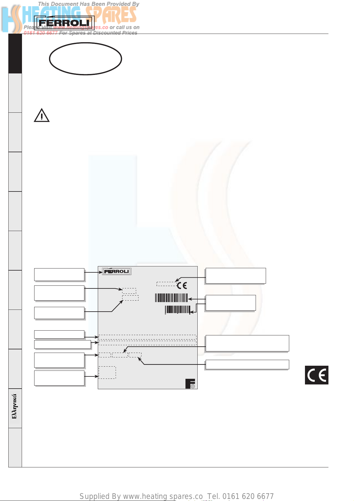
Manufacturer
Trade name
Serial number
• This manual provides important indications on the safety
of operation, installation and maintenance, and is an
integral and essential part of the product. Read this
manual before installation and operation. It should be
carefully kept for future reference.
• This appliance must only be used for the purposes it
has been specifically designed for. This appliance is
used to heat water to below-boiling temperatures at
atmospheric pressure, and must be connected to a
heating and/or domestic hot water distribution system,
according to its characteristics, performance and heating
capacity. All other uses are considered improper and
thus dangerous.
• The appliance may not be opened nor its components
tampered with, except for the parts included in the
maintenance operations. The appliance may not be
modified to alter its performance or use.
• The installation and maintenance operations must be
performed according to the standards in force, the
instructions of the manufacturer and must be carried
out by professionally qualified personnel.
Ferroli Spa
Via Ritonda 78A 37047 San Bonifacio (VR) - Italia
EN303 - Appr.No.
PIN
Type
N°
GN4 N 07
0000000000
C97.02G 07
CE-0085AS0589
1QGDX05B
028693 3301698
• Incorrect installation or poor maintenance may cause
damage to people, animals or things. The manufacturer
declines all liability for damage deriving from errors in
the installation and operation of the appliance, and in
any case from the failure to observe the instructions
provided.
• Before performing any cleaning or maintenance
operations, disconnect the appliance from the mains
power supply using the system switch and/or the
corresponding on-off devices.
• In the event of faults and/or poor operation of the
appliance, it should be deactivated. Do not attempt to
repair the appliance. Contact professionally qualified
personnel only.
• After having removed the packaging, check that the
contents are intact. The parts of the packaging must
not be left within the reach of children, as they are
potential sources of danger.
PIN
0085
Bar code
MAX. MIN.
DanskTürkçe
Heat output
Uselful heat output
Max operating
pressure
Electrical power
Q (Hi)-INPUT
P -OUTPUT
PMS 4 bar - Tmax 110 °C- - H2O 143 I
230 V - ~50 Hz
IPX0D
217 128
200 120kWkW
supply
2
Max operating pressure
temperature
Water content
Certification
The CE Mark attests that Ferroli appliances
conform to the requirements specified in the
applicable European directives.
In particular, this appliance conforms to the
following EEC directives:
• Gas directive 90/396
• Efficiency directive 92/42
• Low voltage directive 73/23 (amended by 93/
68)
• Electromagnetic compatibility directive 89/336
(amended by 93/68)
Page 3
Supplied By www.heating spares.co Tel. 0161 620 6677
GN4 N
1. OPERATING INSTRUCTIONS
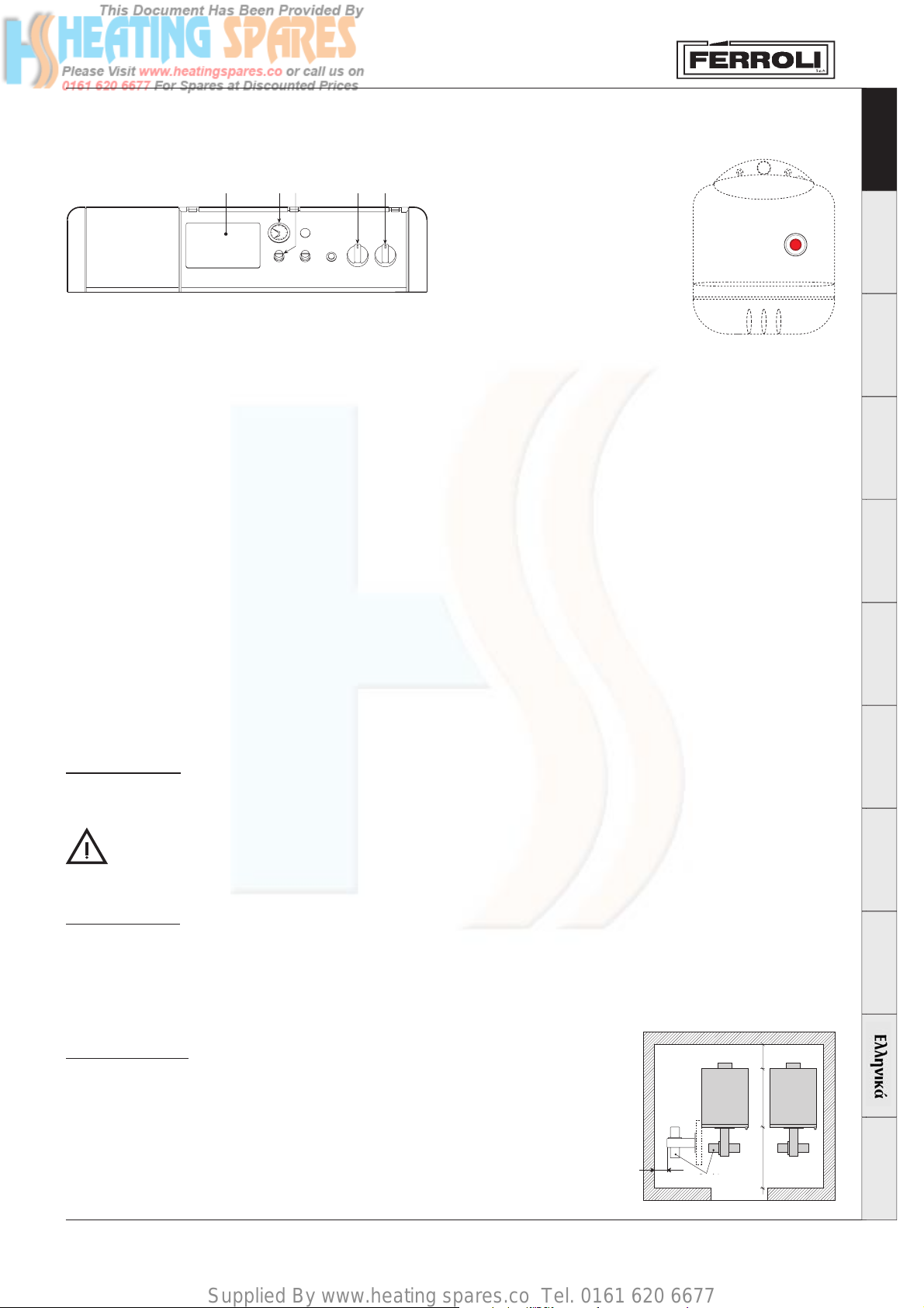
1.1 Control panel
English DeutschItaliano Français Español
21453
Key
1 Ready for electronic control unit
2 Thermometer
3 Safety thermostat
4 Control thermostat, 2 Stages
5 Line switch “0 - I - TEST”
6 Burner lockout indicator light
fig. 1
6
1.2 Ignition
Move the main switch 5 to position “I” to power the boiler and the burner. Refer to the burner manual for the operation of this device.
1.3 Setting
Set the desired system temperature using the control thermostat 4. If the thermoregulation control unit (optional) is connected, refer to the
corresponding instruction manual.
1.4 Shut-down
For brief periods of inactivity, simply move switch 5 (Fig. 1) on the control panel to position “0”.
For extended periods of inactivity, as well as operating switch 5, the fuel on-off valve must also be closed.
For extended periods of inactivity during the winter period, to avoid damage from frost, add special antifreeze to the system or drain the system
completely.
1.5 Anomalies
Two lockout conditions may occur that can be reset by the user:
a - Burner lockout signalled by the corresponding light 6 (Fig. 1). Refer to the burner manual.
b - Activation of the safety thermostat when the temperature in the boiler reaches the limit value above which a dangerous situation may arise.
To reset operation, unscrew cap 3 and press the reset button.
If the problem occurs again, contact qualified personnel or the service centre.
In the event of faults and/or poor operation of the appliance, it should be deactivated. Do not attempt to repair the appliance. Contact professionally
qualified and authorised personnel only.
Português Nederlands
2. INSTALLATION
General instructions
This appliance must only be used for the purposes it has been specifically designed for. This appliance is used to heat water to below-boiling
temperatures at atmospheric pressure, and must be connected to a heating and/or domestic hot water distribution system, according to its
characteristics, performance and heating capacity. All other uses are considered improper.
THE BOILER MUST ONL Y BE INST ALLED BY QUALIFIED AND SPECIALIST PERSONNEL, IN COMPLETE COMPLIANCE WITH ALL THE
INSTRUCTIONS REPORTED IN THIS TECHNICAL MANUAL, THE LEGAL STANDARDS IN FORCE, THE PRESCRIPTIONS OF ANY
NATIONAL AND LOCAL STANDARDS, AND ACCORDING TO THE RULES OF GOOD PRACTICE.
Incorrect installation may cause damage to people, animals and things. The manufacturer will not be held liable in such events.
Place of installation
The room in which the boiler is installed must have ventilation openings to the outside according to the standards in force. If the same room
features a series of burners or exhaust devices that can operate at the same time, the ventilation openings must be large enough for the
simultaneous operation of all the appliances.
The place of installation must be free of flammable objects or materials, corrosive gas, dust or volatile substances that, sucked in by the
burner’s fan, may block the internal tubing of the burner or the combustion head. The environment must be dry and not exposed to rain, snow
or frost.
Positioning the boiler
The minimum spaces shown in the figure must be complied with. Specifically, make sure that after
assembling the boiler with the burner on the front door, the latter can be opened without the burner
hitting against the wall or any other boiler . Leave a free space of at least 100mm on the side that the door
swings towards.
fig. 2
100
mm
Bruciatore
Burner
550==
Dansk Türkçe
3
Page 4
Supplied By www.heating spares.co Tel. 0161 620 6677
2.1 Water connections
Make the water connections to the appliance according to the indications shown both next to each fitting and in Figure 2 of this booklet.
The connections must be made in such a way that the pipes are not under stress. The safety valve must be fitted in the central heating circuit,
EnglishDeutsch ItalianoFrançaisEspañol
as close as possible to the boiler, without there being any obstructions or on-off devices between the boiler and the valve.
The appliance is not supplied with an expansion vessel, and therefore such device must be connected by the installer. Please note that in this
regard, the pressure in the system, when cold, must be between 0.5 and 1 bar.
2.2 Connecting the burner
Oil or gas jet burners for pressurised furnaces can be used if their operating characteristics are suitable for the dimensions of the boiler’s
furnace and its over-pressure value. The burner must be chosen following the instructions provided by the manufacturer, according to the field
of operation, fuel consumption and pressure, as well as the length of the combustion chamber.
Fit the burner following the instructions provided by the manufacturer of the device.
2.3 Electrical connections
The boiler should be connected to a single-phase, 230 Volt-50 Hz electrical line, using a permanent connection, installing a double
pole switch with contact openings of at least 3mm, and suitable fuses. Connect the burner and the room thermostat (if featured) as
shown in the wiring diagram in Chap. 4.
The electrical safety of the appliance is ensured only when the appliance is correctly connected to an effective earth system, as prescribed by
the safety standards in force. Have professionally qualified personnel check the efficiency and the rating of the earth system. The manufacturer
is not liable for any damage caused by the appliance not being correctly earthed. In addition, make sure that the electrical system is adequately
rated for the maximum power absorbed by the appliance, indicated on the rating plate, and in particular that the cross-section of the wires is
suitable for the power absorbed by the appliance.
2.4 Flue connections
The boiler should be connected to a suitable flue, manufactured in compliance with the standards in force. The pipe between boiler and the flue
must be made from material suitable for this purpose, that is, resistant to both high temperatures and corrosion. The joints should be carefully
sealed and the entire length of the pipe between the boiler and the flue should be thermally insulated, to avoid the formation of condensate.
GN4 N
2.5 Assembling the boiler
The boiler may be supplied:
1. As a set of elements, in 4 separate boxes, containing the Casing, Control panel, Elements, and accessories for assembling the elements.
Follow the instructions enclosed with the set of elements to assemble the boiler body. Follow the instructions below to assemble the casing
and control panel.
2. With the body already assembled, in 3 separate boxes containing the Casing, Control panel and Boiler body.
PortuguêsNederlands
DanskTürkçe
Follow the instructions below to assemble the casing and the control panel.
1
A
A If the boiler body is
supplied already
assembled and is
1
2
2
B
B Fit the rear panel 1 on the
studs 2 and loosely
tighten the bolts.
1
7 elem.
8 elem.
2
9 elem.
10 elem.
11 elem.
2
12 elem.
13 elem.
14 elem.
F. ant. DX e SX +
F. ant. DX e SX +
F. ant. DX e SX +
F. ant. DX e SX +
F. ant. DX e SX +
F. ant. DX e SX +
F. ant. DX e SX +
F. ant. DX e SX +
delivered from the
factory on a pallet,
C
remove the bolts 1
that fasten it to the
pallet and position it
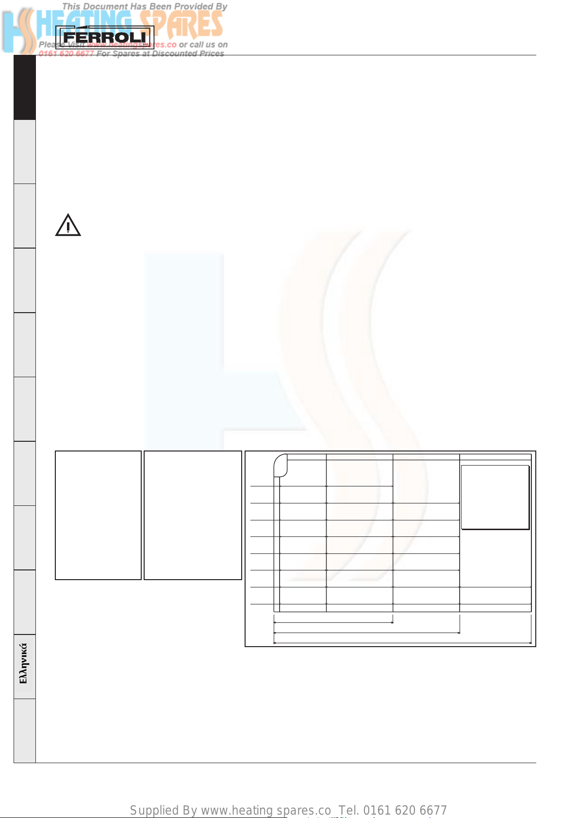
C Prepare the right and left sides, choosing the quantity of side panels according to
the dimensions of the boiler (see table).
for final installation.
Then assemble the
various panels.
Fianchi
F. ant. DX = 330 mm (cod. 3703812/0)
cop. ant. F. 3 + Cop. 3
cop. ant. F. 1 + Cop. 1 F. 1 + Cop. 1
cop. ant. F. 2 + Cop. 2 F. 1 + Cop. 1
cop. ant. F. 2 + Cop. 2 F. 2 + Cop. 2
cop. ant. F. 2 + Cop. 2 F. 3 + Cop. 3
cop. ant. F. 3 + Cop. 3 F. 3 + Cop. 3
cop. ant. F. 1 + Cop. 1 F. 2 + Cop. 2 F. 2 + Cop. 2
cop. ant. F. 2 + Cop. 2 F. 2 + Cop. 2 F. 2 + Cop. 2
7 elementi
9÷12 elementi
13÷14 elementi
F. ant. SX = 330 mm (cod. 3703813/0)
F. 1 = 406 mm (cod. 3703814/0)
F. 2 = 536 mm (cod. 3703815/0)
F. 3 = 666 mm (cod. 3703816/0)
Coperchi
Cop. ant. = 273 mm (cod. 3703822/0)
Cop. 1 = 406 mm (cod. 3703819/0)
Cop. 2 = 536 mm (cod. 3703820/0)
Cop. 3 = 666 mm (cod. 3703821/0)
4
Page 5
Supplied By www.heating spares.co Tel. 0161 620 6677
GN4 N
English DeutschItaliano Français Español
B
B
B
E
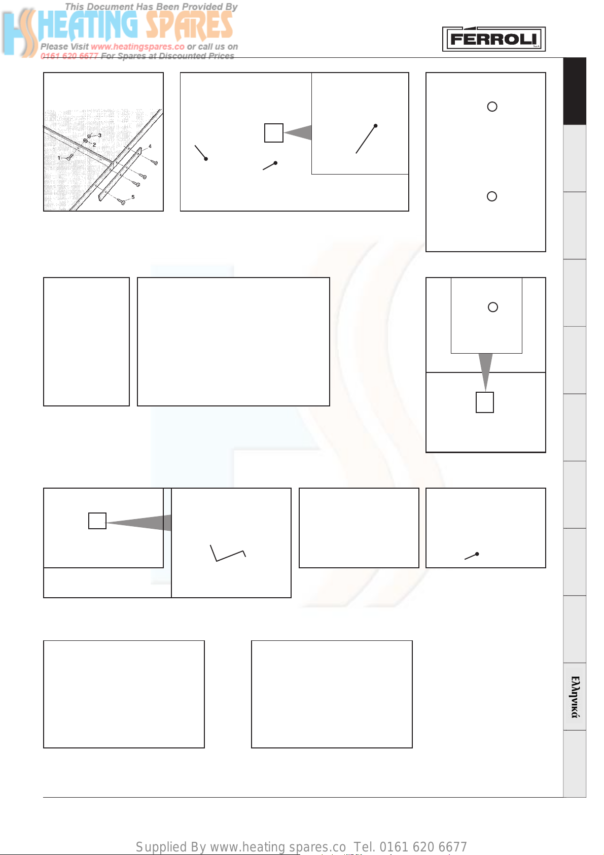
D Connect the panels together, using the screws 1, the washers 2 and the nuts 3,
reinforcing the bottom parts using the blades 4 fastened with the screws 5.
E Loosen the nuts “A”. Insert the side fastening bracket “B”
F Fasten the sides to the rear wall “A” using the screws “B”.
B
A
B
A
B
G
G Fit the side to the bracket “A” and fasten it using the screws “B” (right
side view). Repeat the operations in point G for the left side.
H Fasten the sides to the rear wall “A” using the screws “B”.
I Fit the wiring protection case “A” using the screws “B” on the sides.
H
B
A
A
B
F
B
A
Português Nederlands
I
A
B
L
L Fit the control panel to the sides using the tabs “A”. Place
the reinforcement spring “B” between the head of the screw
and the tab.
A
O
O Fit the upper panel “A”.
P Fit the top cover or covers “A”, according to the length of the boiler (see table 1, sequence C).
P
MN
MInsert the 3 bulbs (safety thermostat, boiler thermostat and
thermometer).
N Fit the lower front panel “A”.
A
Dansk Türkçe
A
5
Page 6
Supplied By www.heating spares.co Tel. 0161 620 6677
3. SERVICE AND MAINTENANCE
All the adjustment, commissioning and maintenance operations must be performed by Qualified Personnel, in compliance with the standards
in force.
EnglishDeutsch ItalianoFrançaisEspañol
FERROLI S.p.A. declines all liability for damage to persons and/or things deriving from the tampering with the appliance by unqualified or
unauthorised persons.
Before performing any cleaning or maintenance operations, disconnect the appliance from the mains power supply using the system switch
and/or the special on-off devices.
3.1 Commissioning
Checks to be performed on first ignition, and after all maintenance operations that involve the disconnection of the appliance from the systems
or intervention on the safety devices or parts of the boiler:
Before first ignition
Before igniting the boiler for the first time, check that:
a the system is filled at the right pressure and any air has been correctly vented;
b there are no water or fuel leaks;
c the electrical power supply is correct;
d all the flues have been installed correctly and not too near to or across any flammable parts;
e there are no flammable substances near the appliance;
f the burner is suitably sized for the output of boiler;
g the water on-off valves are open.
First ignition
After having carried out the preliminary checks, the following ignition operations can be performed:
1 Open the fuel on-off valve.
2 Set the thermostat 4 (Fig. 1) to the desired value.
3 Close the switch upstream from the boiler and switch 5 (Fig. 1) on the control panel.
At this stage, the burner will be ignited and the boiler will start operation.
GN4 N
After first ignition
After first ignition, check that:
1 The door of the burner and smokebox are well sealed.
2 The burner is working correctly. This check should be performed using the required instruments, following the manufacturer’s instructions.
3 The thermostats are working correctly.
PortuguêsNederlands
4 Water is circulating in the system.
5 The flue gas is completely expelled through the flue.
3.2 Adjustments
Adjusting the burner
The efficiency and correct operation of the boiler depend above all on accuracy of the adjustments made to the burner.
Carefully follow the instructions provided by the manufacturer. Two-stage burners must have the first stage adjusted to an output that is no
lower than the minimum rated output of the boiler. The output of the second stage must not be gr eater than the maximum rated output of the
boiler.
3.3 Shut-down
DanskTürkçe
For brief periods of inactivity, simply use switch 5 (Fig. 1) on the control panel.
For extended periods of inactivity, as well as operating switch 5, the fuel on-off valve must also be closed.
3.4 Maintenance
To ensur e the maximum reliability of the heating system and minimum running costs, the boiler must be cleaned regularly , at least once a year.
These maintenance operations must be performed by qualified and specialist personnel.
Cleaning the boiler
1 Disconnect the power supply to the boiler
2 Remove the upper and lower front panel.
3 Open the door by unscrewing the knobs.
4 Clean the inside of the boiler and the entire flue gas discharge path, using a brush or compressed air.
5 Close the door again, and fasten it using the knob.
To clean the burner, refer to the instructions provided by the manufacturer.
6
Page 7
Supplied By www.heating spares.co Tel. 0161 620 6677
GN4 N
140
40
0
0 5 10 15 20 25 30 35
m
3
/h
20
40
60
80
100
120
mbar
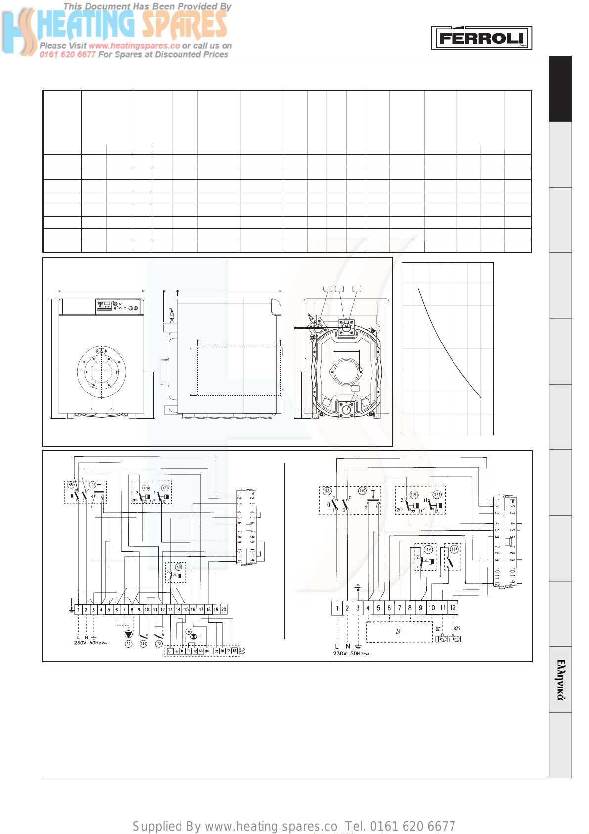
4. TECHNICAL SPECIFICATIONS
English DeutschItaliano Français Español
Modello
GN4 N 07
GN4 N 08
GN4 N 09
GN4 N 10
GN4 N 11
GN4 N 12
GN4 N 13
GN4 N 14
1193
Heat input
gas+oil
(NHV) kW
Max
217
270
324
388
452
516
600
695
850
0
B
Min
128
160
192
229
266
309
352
416
output
Max
200
250
300
360
420
480
560
650
Heat
kW
463
Min
120
150
180
215
250
290
330
390
N°
elem.
7
8
9
10
11
12
13
14
D
Water
content
dm3
143
163
183
203
223
243
263
283
A138
Operating
pressure
E
bar
Comb.
A
B
C
D
E
chamber
pressure
drop
Ø
Ø
mm
mm
4
1040
210
4
1170
210
4
1300
210
4
1430
210
4
1560
210
4
1690
210
4
1820
210
4
1950
210
10
mm
180
180
250
250
250
250
250
250
Ø
mm
mm
∆p mbar
500
880
500
1010
500
1140
500
1270
500
1400
500
1530
500
1660
500
1790
A1B2B1
C
0,5
0,8
0,7
1,0
1,4
1,7
2,6
3,5
Comb.
chamber
volume
dm3
161,3
185,1
208,9
232,8
256,6
280,4
304,3
328,1
Water
pressure
drop
∆t 10
-
-
-
-
-
-
-
-
∆t 20
20
30
42
54
65
77
88
100
Body
weight
kg
840
950
1060
1170
1280
1390
1500
1610
fig. 4
898
38083
A2
Português Nederlands
GN4 N 6-7-8
Legenda
A1 Central heating flow outlet DN80 - 3”
A2 Central heating return inlet DN80 - 3”
B1 Central heating flow outlet DN80 - 3”
(Low temperature)
B2 Central heating return inlet DN80 - 3”
(Low temperature)
GN4 N 10-11-12-13-14
fig. 5
32 Pump (not supplied)
49 Safety thermostat
72 Room thermostat (not supplied)
98 Switch
114 Water pressure Switch
159 Test knob
170 Boiler setting thermostat, 1st stage
171 Boiler setting thermostat, 2nd stage
189 Lockout indicator light (not supplied)
211 Burner connector
fig. 3
Dansk Türkçe
Note The dashed sections of wiring are the
responsibility of the installer
7
 Loading...