

Ferroli GN2 N 07, GN2 N 09, GN2 N 10, GN2 N 11, GN2 N 12 Operating, Installation And Maintenance Manual
...
GN2 N
high-efficiency cast iron boiler for liquid fuels and/or gas
OPERATING, INSTALLATION AND MAINTENANCE INSTRUCTIONS
caldaia di ghisa ad alto rendimento per combustibili liquidi e/o gassosi
ISTRUZIONI PER LUSO LINSTALLAZIONE E LA MANUTENZIONE
chaudière en fonte a haut rendement pour combustibles liquides et/ou gazeux
INSTRUCTIONS POUR LINSTALLATION ET LENTRETIEN
heizkessel aus gusseisen mit hohem wirkungsgrad für flüssige und/oder gasförmige brennstoffe
INSTALLATIONS-, BEDIENUNGS- UND WARTUNGSANLEITUNGEN
caldera de fundición, de alto rendimiento para combustibles líquidos y/o gaseosos
INSTRUCCIONES DE USO, INSTALACIÓN Y MANTENIMIENTO
caldeira em ferro fundido de alto rendimento para combustíveis líquidos e/ou gasosos
INSTRUÇÕES PARA O USO, INSTALAÇÃO E MANUTENÇÃO
verwarmingsketel in gietijzer met hoog rendement voor vloeibare en/of gasvormige brandstof
AANWIJZINGEN VOOR HET GEBRUIK, DE INSTALLATIE EN HET ONDERHOUD
støbejernsfyr med øget udbytte til flydende brændstof og/eller gas
INSTRUKTIONER VEDRØRENDE BRUG, INSTALLATION OG VEDLIGEHOLDELSE
GB
IT
FR
DE
ES
PT
NL
DK
TR
cod. 3544122/6 - 01/2012 (Rev. 00)
sivi ve/veya gaz yakitli yüksek ver‹ml‹
DÖKÜM DÖLMLÖ KAZAN

EnglishDeutsch ItalianoFrançaisEspañol
PortuguêsNederlands
DanskTürkçe
2
GN2 N
Cod. 35441226 - 01/2012 (Rev. 00)
Dear Customer,
Thank you for having chosen the GN2 N, an advanced-concept Ferroli boiler featuring cutting-edge technology, high reliability and constructional quality. Carefully read this manual
and keep it for future reference.
The GN2 N is a high-ef¿ ciency heat generator for the production of hot water for heating
purposes, suitable for operation with jet burners on gas or liquid fuel.
The boiler body consists of cast-iron elements, the shape of which, together with the careful
design of the ¿ ns, ensure high heat exchange ef¿ ciency in all operating conditions.
Important warnings
• This manual provides important indications on the safety of
operation, installation and maintenance, and is an integral
and essential part of the product. Read this manual before
installation and operation. It should be carefully kept for future
reference.
• This appliance must only be used for the purposes it has been
speci¿ cally designed for. This appliance is used to heat water
to below-boiling temperatures at atmospheric pressure, and
must be connected to a heating and/or domestic hot water distribution system, according to its characteristics, performance
and heating capacity. All other uses are considered improper
and thus dangerous.
• The appliance may not be opened nor its components tampered with, except for the parts included in the maintenance
operations. The appliance may not be modi¿ ed to alter its
performance or use.
• The installation and maintenance operations must be performed according to the standards in force, the instructions of
the manufacturer and must be carried out by professionally
quali¿ ed personnel.
• Incorrect installation or poor maintenance may cause damage
to people, animals or things. The manufacturer declines all
liability for damage deriving from errors in the installation and
operation of the appliance, and in any case from the failure to
observe the instructions provided.
• Before performing any cleaning or maintenance operations,
disconnect the appliance from the mains power supply using
the system switch and/or the corresponding on-off devices.
• In the event of faults and/or poor operation of the appliance, it
should be deactivated. Do not attempt to repair the appliance.
Contact professionally quali¿ ed personnel only.
• After having removed the packaging, check that the contents
are intact. The parts of the packaging must not be left within the
reach of children, as they are potential sources of danger.
ENGLISH
Electrical power
supply
Max operating
pressure temperature
PIN
Serial number
Max operating
pressure
Heat output
Uselful heat output
Bar code
Water content
12/245
0085AS0420
0085
230V~50Hz IP
X 0D
Ser. n. 0352L50349
Q
P
-
-
kW
kW
234,7
216
max
185
171
min
PMS
tmax
6
100
bar
°C
PMW
D
bar
l/min
Appr. nr.
H2O
105 L
Certi¿ cation
The CE Mark attests that Ferroli appliances conform
to the requirements speci¿ ed in the applicable Eu-
ropean directives.
In particular, this appliance conforms to the following
EEC directives:
• Gas directive 2009/142
• Ef¿ ciency directive 92/42
• Low voltage directive 2006/95
• Electromagnetic compatibility directive 2004/108

3
English DeutschItaliano Français Español
Português Nederlands
Dansk Türkçe
GN2 N
Cod. 35441226 - 01/2012 (Rev. 00)
1. OPERATING INSTRUCTIONS
1.1 Control panel
123
4
5
1.2 Ignition
Move the main switch 5 to position “I” to power the boiler and the burner. Refer to the burner manual for the operation of this device.
1.3 Setting
Set the desired system temperature using the control thermostat 4. If the thermoregulation control unit (optional) is connected, refer to the
corresponding instruction manual.
1.4 Shut-down
For brief periods of inactivity, simply move switch 5 (Fig. 1) on the control panel to position “0”.
For extended periods of inactivity, as well as operating switch 5, the fuel on-off valve must also be closed.
For extended periods of inactivity during the winter period, to avoid damage from frost, add special antifreeze to the system or drain the system
completely.
1.5 Anomalies
Two lockout conditions may occur that can be reset by the user:
a - Burner lockout signalled by the corresponding light 6 (Fig. 1). Refer to the burner manual.
b - Activation of the safety thermostat when the temperature in the boiler reaches the limit value above which a dangerous situation may arise.
To reset operation, unscrew cap 3 and press the reset button.
If the problem occurs again, contact quali¿ ed personnel or the service centre.
In the event of faults and/or poor operation of the appliance, it should be deactivated. Do not attempt to repair the appliance. Contact professionally quali¿ ed and authorised personnel only.
2. INSTALLATION
General instructions
This appliance must only be used for the purposes it has been speci¿ cally designed for. This appliance is used to heat water to below-boiling
temperatures at atmospheric pressure, and must be connected to a heating and/or domestic hot water distribution system, according to its
characteristics, performance and heating capacity. All other uses are considered improper.
THE BOILER MUST ONLY BE INSTALLED BY QUALIFIED AND SPECIALIST PERSONNEL, IN COMPLETE COMPLIANCE WITH
ALL THE INSTRUCTIONS REPORTED IN THIS TECHNICAL MANUAL, THE LEGAL STANDARDS IN FORCE, THE PRESCRIPTIONS OF ANY NATIONAL AND LOCAL STANDARDS, AND ACCORDING TO THE RULES OF GOOD PRACTICE.
Incorrect installation may cause damage to people, animals and things. The manufacturer will not be held liable in such events.
Place of installation
The room in which the boiler is installed must have ventilation openings to the outside according to the standards in force. If the same room
features a series of burners or exhaust devices that can operate at the same time, the ventilation openings must be large enough for the
simultaneous operation of all the appliances.
The place of installation must be free of À ammable objects or materials, corrosive gas, dust or volatile substances that, sucked in by the bur-
ner’s fan, may block the internal tubing of the burner or the combustion head. The environment must be dry and not exposed to rain, snow or
frost.
Positioning the boiler
The minimum spaces shown in the ¿ gure must be complied with. Speci¿ cally, make sure that after as-
sembling the boiler with the burner on the front door, the latter can be opened without the burner hitting
against the wall or any other boiler. Leave a free space of at least 100mm on the side that the door swings
towards.
6
100
mm
550==
Key
1 Ready for electronic control unit
2 Thermohydrometer
3 Safety thermostat
4 Control thermostat, 2 Stages
5 Line switch “0 - I - TEST”
6 Burner lockout indicator light
¿ g. 1
¿ g. 2
Burner

EnglishDeutsch ItalianoFrançaisEspañol
PortuguêsNederlands
DanskTürkçe
4
GN2 N
Cod. 35441226 - 01/2012 (Rev. 00)
2.1 Water connections
Make the water connections to the appliance according to the indications shown both next to each ¿ tting and in Figure 2 of this booklet.
The connections must be made in such a way that the pipes are not under stress. The safety valve must be ¿ tted in the central heating circuit,
as close as possible to the boiler, without there being any obstructions or on-off devices between the boiler and the valve.
The appliance is not supplied with an expansion vessel, and therefore such device must be connected by the installer. Please note that in this
regard, the pressure in the system, when cold, must be between 0.5 and 1 bar.
2.2 Connecting the burner
Oil or gas jet burners for pressurised furnaces can be used if their operating characteristics are suitable for the dimensions of the boiler’s
furnace and its over-pressure value. The burner must be chosen following the instructions provided by the manufacturer, according to the ¿ eld
of operation, fuel consumption and pressure, as well as the length of the combustion chamber.
Fit the burner following the instructions provided by the manufacturer of the device.
2.3 Electrical connections
The boiler should be connected to a single-phase, 230 Volt-50 Hz electrical line, using a permanent connection, installing a double
pole switch with contact openings of at least 3mm, and suitable fuses. Connect the burner and the room thermostat (if featured) as
shown in the wiring diagram in Chap. 4.
The electrical safety of the appliance is ensured only when the appliance is correctly connected to an effective earth system, as
prescribed by the safety standards in force. Have professionally quali¿ ed personnel check the ef¿ ciency and the rating of the earth system.
The manufacturer is not liable for any damage caused by the appliance not being correctly earthed. In addition, make sure that the electrical
system is adequately rated for the maximum power absorbed by the appliance, indicated on the rating plate, and in particular that the crosssection of the wires is suitable for the power absorbed by the appliance.
2.4 Flue connections
The boiler should be connected to a suitable À ue, manufactured in compliance with the standards in force. The pipe between boiler and the À ue
must be made from material suitable for this purpose, that is, resistant to both high temperatures and corrosion. The joints should be carefully
sealed and the entire length of the pipe between the boiler and the À ue should be thermally insulated, to avoid the formation of condensate.
2.5 Assembling the boiler
The boiler may be supplied:
1. As a set of elements, in 4 separate boxes, containing the Casing, Control panel, Elements, and accessories for assembling the elements.
Follow the instructions enclosed with the set of elements to assemble the boiler body. Follow the instructions below to assemble the casing
and control panel.
2. With the body already assembled, in 3 separate boxes containing the Casing, Control panel and Boiler body.
Follow the instructions below to assemble the casing and the control panel.
Cover type 5 Cover type 5 Cover type 1, 2, 3 e 4Cover type 5 Cover type 1, 2, 3 e 4
Cover type 1, 2, 3 e 4
Version 13-14 Elements
R and L sides
Type: 1,2,3,4
Reversible
side
Reversible
side
L
B440440 57
Version 9-12 Elements
R and L sides
Type: 1,2,3,4
Reversible
side
L
B440 57
AA
Version 5-8 Elements
R and L sides
Type: 1,2,3,4
B
57
A
Quantity
GN2 N
GN2 N
GN2 N
GN2 N
GN2 N
GN2 N
GN2 N
GN2 N
GN2 N
GN2 N
L
5
6
7
8
9
10
11
12
13
14
604
714
824
934
604
714
824
934
604
714
Model
AB
547
657
767
877
547
657
767
877
547
657
/
/
/
/
1044
1154
1264
1374
1484
1594
Cover
type
R side
type
Rev. side
2
2
2
2
4
4
N° Elem.
1
1
1
1
2
1
1
1
3
1
1
4
1
1
1
1
1
1
2
1
1
1
3
1
1
4
1
1
1
1
1
1
2
1
1
1
3
1
1
4
1
1
5
1
1
1
1
2
2
L side
type
C Prepare the right and left sides, choosing the quantity of side panels according to the dimensions of the boiler (see table).
C
B
1
2
2
2
2
A1
A2
A If the boiler body is supplied assem-
bled, it comes from the factory arranged horizontally on a pallet. Remove
the body from the pallet and position
it upright in the place of installation.
Apply the insulation on the body, then
¿ t the various panels.
B Fit the rear panel 1 on the studs 2 and
loosely tighten the bolts.

5
English DeutschItaliano Français Español
Português Nederlands
Dansk Türkçe
GN2 N
Cod. 35441226 - 01/2012 (Rev. 00)
E F
G
H
I
L
M
NO
P
Q
D
B
A
B
A
B
A
A
B
B
A
B
A
A
A
A
D Connect the panels together, using the screws 1, the washers 2 and the nuts 3,
reinforcing the bottom parts using the blades 4 fastened with the screws 5.
E Loosen the nuts “A”.
F Insert the side fastening bracket “A” between nuts “A” and “B”.
G Fit the side to the bracket “A” and fasten it using the screws “B” (right side view). Repeat the
operations in point G for the left side.
H Fasten the sides to the rear wall “A” using the screws “B”.
I Unwind the hydrometer capillary tubing and tighten its connector to the sheathing on the front
of the boiler body.
L Fit the wiring protection case “A” using the screws “B” on the sides.
M Fit the control panel to the sides using the tabs “A”. Place the
reinforcement spring “B” between the head of the screw and
the tab.
N Insert the 3 bulbs (safety thermostat, boiler thermostat and
thermohydrometer).
O Fit the lower front panel “A”.
P Fit the upper panel “A”.
Q Fit the top cover or covers “A”, according to the length of the boiler (see table 1, sequence C).

EnglishDeutsch ItalianoFrançaisEspañol
PortuguêsNederlands
DanskTürkçe
6
GN2 N
Cod. 35441226 - 01/2012 (Rev. 00)
3. SERVICE AND MAINTENANCE
All the adjustment, commissioning and maintenance operations must be performed by Quali¿ ed Personnel, in compliance with the standards
in force.
FERROLI S.p.A. declines all liability for damage to persons and/or things deriving from the tampering with the appliance by unquali¿ ed or
unauthorised persons.
Before performing any cleaning or maintenance operations, disconnect the appliance from the mains power supply using the system switch
and/or the special on-off devices.
3.1 Commissioning
Checks to be performed on ¿ rst ignition, and after all maintenance operations that involve the disconnection of the appliance from the systems
or intervention on the safety devices or parts of the boiler:
Before ¿ rst ignition
Before igniting the boiler for the ¿ rst time, check that:
a the system is ¿ lled at the right pressure and any air has been correctly vented;
b there are no water or fuel leaks;
c the electrical power supply is correct;
d all the À ues have been installed correctly and not too near to or across any À ammable parts;
e there are no À ammable substances near the appliance;
f the burner is suitably sized for the output of boiler;
g the water on-off valves are open.
First ignition
After having carried out the preliminary checks, the following ignition operations can be performed:
1 Open the fuel on-off valve.
2 Set the thermostat 4 (Fig. 1) to the desired value.
3 Close the switch upstream from the boiler and switch 5 (Fig. 1) on the control panel.
At this stage, the burner will be ignited and the boiler will start operation.
After ¿ rst ignition
After ¿ rst ignition, check that:
1 The door of the burner and smokebox are well sealed.
2 The burner is working correctly. This check should be performed using the required instruments, following the manufacturer’s instruc-
tions.
3 The thermostats are working correctly.
4 Water is circulating in the system.
5 The À ue gas is completely expelled through the À ue.
3.2 Adjustments
Adjusting the burner
The ef¿ ciency and correct operation of the boiler depend above all on accuracy of the adjustments made to the burner.
Carefully follow the instructions provided by the manufacturer. Two-stage burners must have the ¿ rst stage adjusted to an output that is no
lower than the minimum rated output of the boiler. The output of the second stage must not be greater than the maximum rated output of
the boiler.
3.3 Shut-down
For brief periods of inactivity, simply use switch 5 (Fig. 1) on the control panel.
For extended periods of inactivity, as well as operating switch 5, the fuel on-off valve must also be closed.
3.4 Maintenance
To ensure the maximum reliability of the heating system and minimum running costs, the boiler must be cleaned regularly, at least once a year.
These maintenance operations must be performed by quali¿ ed and specialist personnel.
Cleaning the boiler
1 Disconnect the power supply to the boiler
2 Remove the upper and lower front panel.
3 Open the door by unscrewing the knobs.
4 Clean the inside of the boiler and the entire À ue gas discharge path, using a brush or compressed air.
5 Close the door again, and fasten it using the knob.
To clean the burner, refer to the instructions provided by the manufacturer.

7
English DeutschItaliano Français Español
Português Nederlands
Dansk Türkçe
GN2 N
Cod. 35441226 - 01/2012 (Rev. 00)
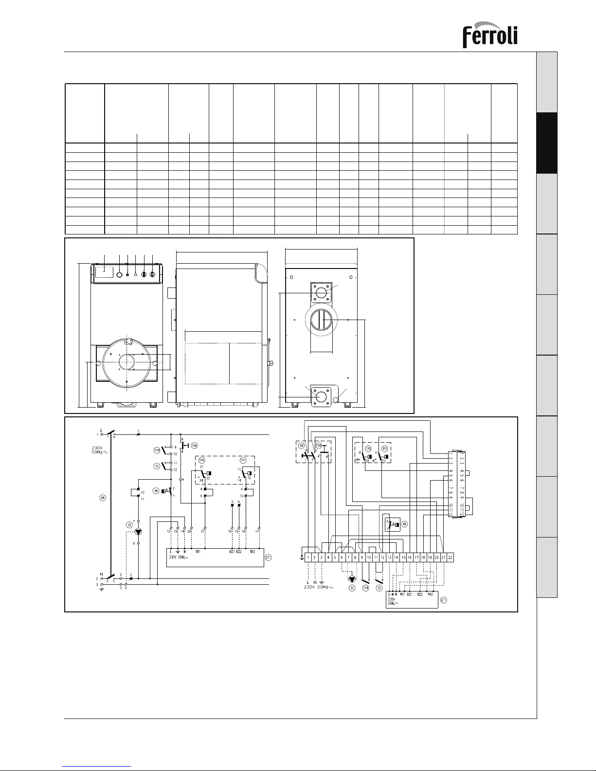
4. TECHNICAL SPECIFICATIONS
Water
pressure
drop
Model
GN2 N 05
GN2 N 06
GN2 N 07
GN2 N 08
GN2 N 09
GN2 N 10
GN2 N 11
GN2 N 12
GN2 N 13
GN2 N 14
98,8
116,0
136,9
156,5
176,0
195,6
215,2
234,7
254,3
273,9
Max
80
95
110
125
140
155
170
185
200
215
Min
Heat output
kW
90
107
126
144
162
180
198
216
234
252
Max
73
87
101
115
129
143
157
171
185
199
Min
Heat input gas+oil
(NHV) kW
5
6
7
8
9
10
11
12
13
14
N°
elem.
49
57
65
73
81
89
97
105
113
121
Water
content
dm3
6
6
6
6
6
6
6
6
6
6
Operating
pressure
bar
647
757
867
977
1087
1197
1307
1417
1527
1637
A
mm
130
130
130
154
154
154
154
154
154
154
B
mm
180
180
180
200
200
200
200
200
200
200
Ø
mm
0,4
0,4
0,4
0,4
0,4
0,4
0,4
0,4
0,4
0,4
Comb.
chamber
pressure
drop
Dp mbar
310
361
412
463
514
565
616
670
725
780
Body
weight
kg
-
0,5
0,8
1,8
2,2
2,6
3,2
4
4,5
Dt 20
2,8
3,4
4,8
6,5
8,5
11
13
16
19
23
Dt 10
63
77
91
104
118
132
146
160
174
187
Comb.
chamber
volume
dm3
123456
375
1196
B
Ø cam. comb.
Lg cam. comb.
A
600
867
A1
A2
A3
84
726
C
Legenda
1 Ready for electronic control unit
2 Thermohydrometer
3 Safety thermostat
4 Control thermostat, 2
nd
Stage
5 Line switch
6 Burner lockout indicator light
a1 Central heating À ow outlet DN80 - 3”
a2 Central heating return inlet DN80 - 3”
a3 Boiler drain 3/4”
32 Pump (not supplied)
49 Safety thermostat
72 Room thermostat (not supplied)
98 Switch
114 Water pressure Switch
159 Test knob
170 Boiler setting thermostat, 1
st
stage
171 Boiler setting thermostat, 2nd stage
211 Burner connector
¿ g. 3
¿ g.4
Note The dashed sections of wiring are
the responsibility of the installer

EnglishDeutsch ItalianoFrançaisEspañol
PortuguêsNederlands
DanskTürkçe
8
GN2 N
Cod. 35441226 - 01/2012 (Rev. 00)
Gentile Cliente,
La ringraziamo di aver scelto GN2 N, una caldaia Ferroli di concezione avan zata,
tecnologia al l’avanguardia, elevata af¿ dabilità e qualità costruttiva. La pre ghiamo
di leg gere attentamente il pre sente ma nuale e di conservarlo con cura per ogni
riferimento futuro.
GN2 N è un generatore termico ad alto ren dimento per produzione di ac qua cal da
per riscaldamento, adat to a fun zionare con bruciatori ad aria sof¿ ata di com bustibile
gassoso o liquido.
Il corpo caldaia è costituito da ele menti in ghisa, la cui con formazione ed il progetto attento dell’alettatura ga rantiscono un’ele vata ef¿ cienza di scambio in tutte
le condizioni di funzionamento.
Avvertenze im portanti
• Il presente ma nuale con tiene im portanti in dicazioni per
la si curezza d’uso, d’in stallazione e di ma nutenzione e
costituisce par te in tegrante ed essenziale del prodotto.
Leggere pri ma del l’installazione e del l’uso. Con servare
con cura per ogni ul teriore con sultazione.
• Questo ap parecchio deve essere de stinato solo al l’uso
per il qua le è stato espres samente pre visto dal costruttore. Questo ap parecchio serve a riscaldare ac qua ad una
temperatura in feriore a quel la di ebol lizione a pres sione
atmosferica e deve essere al lacciato ad un impianto
di ri scaldamento e/o ad un im pianto di di stribuzione
acqua cal da per uso sa nitario, com patibilmente alle
sue ca ratteristiche e pre stazioni ed alla sua potenzialità
termica. Ogni altro uso deve con siderarsi improprio e
quindi pe ricoloso.
• Non è con sentito né aprire o manomettere i com ponenti
dell’apparecchio, ad esclusione delle sole parti previste
nella manutenzione, né è consentito mo di¿care l’apparecchio per alterarne le prestazioni o la de stinazione
d’uso.
• L’installazione e la manutenzione devono essere ef fettuate in ot temperanza alle norme vigenti, secondo le
istruzioni del costruttore e devono essere eseguite da
personale professionalmente qua li¿cato.
• Un’errata installazione o una cattiva manutenzione
possono cau sare danni a persone animale o cose. È
esclusa qualsiasi re sponsabilità del costruttore per i
danni causati da errori nell’installazione e nell’uso e
comunque per inosservanza delle istruzioni date.
• Prima di effettuare qualsiasi operazioni di pulizia o di
manutenzione, disinserire l’apparecchio dalla rete di
alimentazione agendo sul l’interruttore dell’impianto e/o
attraverso gli appositi organi di in tercettazione.
• In caso di guasto e/o cattivo funzionamento del l’apparecchio, disattivarlo, astenendosi da qualsiasi tentativo
di riparazione o di in tervento di retto. Rivolgersi esclusivamente a per sonale pro fessionalmente qua li¿cato.
• Dopo aver rimosso l’imballaggio assicurarsi del l’integrità
del con tenuto. Gli elementi dell’imballaggio non de vono
essere lasciati alla por tata di bambini in quanto po tenziali fonti di pericolo.
ITA LIANO
Certi¿ cazione
La marcatura CE documenta che gli apparecchi Ferroli sono conformi ai re quisiti
contenuti nelle direttive eu ropee ad essi
applicabili.
In particolare questo apparecchio è conforme alle seguenti direttive CEE:
• Direttiva Gas 2009/142
• Direttiva Rendimenti 92/42
• Direttiva Bassa Tensione 2006/95
• Direttiva Compatibilità Elettromagnetica
2004/108
Alimentazione
elettrica
Temperatura max
esercizio
PIN
Numero di serie
Pressione max
esercizio
Potenza termica
Potenza utile
Codice a barre
Contenuto acqua
12/245
0085AS0420
0085
230V~50Hz IP
X 0D
Ser. n. 0352L50349
Q
P
-
-
kW
kW
234,7
216
max
185
171
min
PMS
tmax
6
100
bar
°C
PMW
D
bar
l/min
Appr. nr.
H2O
105 L

9
English DeutschItaliano Français Español
Português Nederlands
Dansk Türkçe
GN2 N
Cod. 35441226 - 01/2012 (Rev. 00)
1. ISTRUZIONI D’USO
1.1 Pannello comandi
123
4
5
1.2 Accensione
Portare l’interruttore principale 5 in posizione “I” per alimentare caldaia e bruciatore. Fare riferimento al manuale del bruciatore per il relativo
funzionamento.
1.3 Regolazione
Impostare la temperatura impianto desiderata tramite il termostato di regolazione 4. Se è collegata la centralina di termoregolazione (opzionale)
riferirsi al relativo manuale di istruzioni.
1.4 Spegnimento
Per brevi periodi di sosta è suf¿ ciente agire sull'interruttore 5 (¿ g. 1) sul pannello comandi portandolo in posizione “0”.
Per lunghi periodi di sosta, oltre ad agire sull'interruttore 5, è d'obbligo chiudere anche la valvola di intercettazione del combustibile.
Per lunghe soste durante il periodo invernale, onde evitare danni causati dal gelo, è necessario in trodurre l'apposito antigelo nell'impianto o
svuotare com pletamente l'impianto.
1.5 Anomalie
Possono veri¿ carsi due condizioni di blocco ripristinabili dall’utente:
a - Blocco del bruciatore segnalato dall’apposita spia 6 (¿ g. 1). Riferirsi al manuale del bruciatore.
b - Intervento del termostato di sicurezza che avviene quando la temperatura in caldaia raggiunge un valore oltre al quale può crearsi una
condizione di pericolo. Per ripristinare il funzionamento, svitare il tappo 3 e premere il pulsante di riarmo.
Se il problema si ripete, richiedere l’intervento di Personale Quali¿ cato o del centro assistenza.
In caso di guasto e/o cattivo funzionamento dell’apparecchio, disattivarlo, astenendosi da qualsiasi tentativo di riparazione o di intervento
diretto. Rivolgersi esclusivamente a personale pro fessionalmente quali¿ cato ed autorizzato.
2. INSTALLAZIONE
Disposizioni generali
Questo apparecchio deve essere destinato solo all’uso per il quale è stato espressamente previsto. Questo apparecchio serve a riscaldare
acqua ad una tem peratura inferiore a quella di ebollizione a pressione atmosferica e deve essere allacciato ad un impianto di riscaldamento
e/o ad un impianto di distribuzione acqua calda per uso sanitario, compatibilmente alle sue caratteristiche e prestazioni ed alla sua potenzialità
termica. Ogni altro uso deve considerarsi improprio.
L'INSTALLAZIONE DELLA CALDAIA DEVE ESSERE EFFETTUATA SOLTANTO DA PERSONALE SPECIALIZZATO E DI SICURA
QUALIFICAZIONE, OT TEMPERANDO A TUTTE LE ISTRUZIONI RIPORTATE NEL PRESENTE MANUALE TECNICO, ALLE DISPOSIZIONI DI LEGGE VIGENTI, ALLE PRE SCRIZIONI DELLE NORME NAZIONALI E LOCALI, SECONDO LE REGOLE DELLA
BUONA TECNICA.
Un’errata installazione può causare danni a persone, animali e cose, nei confronti dei quali il costruttore non può essere ritenuto re sponsabile.
Luogo di installazione
La caldaia deve essere installata in apposito locale con aperture di aerazione verso l’esterno secondo quanto prescritto dalle norme vigenti. Se
nello stesso locale vi sono più bruciatori o aspiratori che possono funzionare assieme, le aperture di aerazione devono essere dimensionate
per il fun zionamento contemporaneo di tutti gli apparecchi.
Il luogo di installazione deve essere privo di oggetti o materiali in¿ ammabili, gas corrosivi polveri o so stanze
volatili che, richiamate dal ventilatore del bruciatore possano ostruire i condotti interni del bru ciatore o la
testa di combustione. L’ambiente deve essere asciutto e non esposto a pioggia, neve o gelo.
Posizionamento caldaia
Rispettare gli spazi minimi riportati in ¿ gura. Accertarsi in particolare che dopo il montaggio della caldaia
con il bruciatore sulla porta anteriore, quest’ultima possa aprirsi senza che il bruciatore vada a sbattere
contro la parete o contro un’eventuale altra caldaia. Lasciare uno spazio libero di almeno 100 mm, dalla
parte verso cui ruota la porta.
6
100
mm
550==
Legenda
1 Predisposizione centralina elettronica
2 Termoidrometro
3 Ter mostato di sicurezza
4 Ter mostato di regolazione 2 Sta dio
5 In terruttore di linea “0 - I - TEST”
6 Lampada spia blocco bruciatore
¿ g. 1
¿ g. 2
BRUCIATORE

EnglishDeutsch ItalianoFrançaisEspañol
PortuguêsNederlands
DanskTürkçe
10
GN2 N
Cod. 35441226 - 01/2012 (Rev. 00)
2.1 Collegamenti Idraulici
Eseguire l’allacciamento idraulico dell’apparecchio rispettando le indicazioni poste in prossimità di ogni attacco e quelle riportate nella ¿ gura
2 di questo libretto.
L’allacciamento deve essere fatto in modo che i tubi siano liberi da tensioni ed è d’obbligo montare la valvola di sicurezza sul circuito riscaldamento, in un punto il più vicino possibile alla caldaia, senza vi sia, tra questa e la valvola, alcuna ostruzione od organo d’in tercettazione.
L’apparecchio non viene fornito di vaso d’espansione, il suo collegamento pertanto, deve essere effettuato a cura dell’Installatore. Si ricorda
a tal proposito, che la pressione nell’impianto, a freddo, deve essere tra 0,5 e 1 bar.
2.2 Collegamento del bruciatore
Il bruciatore a gasolio o a gas, ad aria sof¿ ata per focolari pressurizzati, può essere utilizzato se le sue caratteristiche di funzionamento sono
adatte alle dimensioni del focolare della caldaia ed alla sua sovrappressione. La scelta del bruciatore deve essere fatta preliminarmente seguendo le istruzioni del fabbricante, in funzione del campo di lavoro, dei consumi del combustibile e delle pressioni, nonchè della lunghezza
della camera di combustione.
Montare il bruciatore seguendo le istruzioni del Suo Costruttore.
2.3 Collegamenti elettrici
La caldaia va collegata ad una linea elettrica monofase, 230 Volt-50 Hz, con allacciamento ¿ sso ed in terponendo un interruttore bipo-
lare i cui contatti abbiano una apertura di almeno 3 mm, con fusibili adeguati. Effettuare i collegamenti del bruciatore e del l’eventuale
termostato ambiente secondo lo schema elet trico riportato al cap. 4.
La sicurezza elettrica dell’apparecchio è raggiunta soltanto quando lo stesso è correttamente collegato ad un ef¿ cace impianto di
messa a terra eseguito come previsto dalle vigenti norme di sicurezza. Far veri¿ care da personale professionalmente quali¿ cato l’ef¿ cienza e
l’adeguatezza dell’impianto di terra, il costruttore non è responsabile per eventuali danni causati dalla mancanza di messa a terra dell’impianto.
Far veri¿ care inoltre che l’impianto elettrico sia adeguato alla potenza massima assorbita dall’apparecchio, indicata in targhetta dati, ac certando
in par ticolare che la sezione dei cavi dell’impianto sia idonea alla potenza assorbita dall’apparecchio.
2.4 Collegamento alla canna fumaria
Si raccomanda di collegare la caldaia ad una buona canna fumaria, costruita nel rispetto delle norme vigenti. Il condotto tra caldaia e canna
fumaria deve essere di materiale adatto allo scopo, resistente cioè alla temperatura ed alla corrosione. Nei punti di giunzione si raccomanda
di curare la tenuta e di isolare termicamente tutto il condotto tra caldaia e camino, per evitare la formazione di condensa.
2.5 Assemblaggio caldaia
La caldaia può essere fornita:
1. Con elementi smontati, in 4 colli separati contenenti Mantello, Cruscotto, Elementi, accessori per il montaggio degli elementi.
Seguire le istruzioni allegate al gruppo elementi per l’assemblaggio del corpo caldaia. Seguire le istruzioni seguenti per l’assemblaggio di
mantellatura e cruscotto.
2. Con corpo montato in 3 colli separati contenenti Mantello, Cruscotto, Corpo caldaia.
Seguire le istruzioni seguenti per l’assemblaggio della mantellatura e del cruscotto.
Coperchio tipo 5 Coperchio tipo 5 Coperchio tipo 1, 2, 3 e 4Coperchio tipo 5 Coperchio tipo 1, 2, 3 e 4
Coperchio tipo 1, 2, 3 e 4
Versione 13-14 Elementi
Fianco Dx e Sx
Tipo : 1,2,3,4
Fianco
Reversibile
Fianco
Reversibile
L
B440440 57
Versione 9-12 Elementi
Fianco Dx e Sx
Tipo : 1,2,3,4
Fianco
Reversibile
L
B440 57
A
A
Versione 5-8 Elementi
Fianco Dx e Sx
Tipo : 1,2,3,4
B 57
A
Quantità
GN2 N
GN2 N
GN2 N
GN2 N
GN2 N
GN2 N
GN2 N
GN2 N
GN2 N
GN2 N
L
5
6
7
8
9
10
11
12
13
14
604
714
824
934
604
714
824
934
604
714
Modello
AB
547
657
767
877
547
657
767
877
547
657
/
/
/
/
1044
1154
1264
1374
1484
1594
Coperchio
tipo
Fianco
Dx Tipo
Fianco rev.
2
2
2
2
4
4
N° Elem.
1
1
1
1
2
1
1
1
3
1
1
4
1
1
1
1
1
1
2
1
1
1
3
1
1
4
1
1
1
1
1
1
2
1
1
1
3
1
1
4
1
1
5
1
1
1
1
2
2
Fianco
Sx Tipo
C Preparare le ¿ ancate destra e sinistra, scegliendo la quantità di pannelli laterali, in funzione delle dimensioni della caldaia (vedi tabella).
C
B
1
2
2
2
2
A1
A2
A Se il corpo caldaia è fornito assemblato,
arriva dalla fabbrica su pallet adagiato in
posizione orizzontale. Rimuovere il corpo dal
pallet e collocarlo in posizione verticale nel
luogo previsto per l’installazione de¿ nitiva.
Posizionare l’isolante sul corpo e procedere
quindi al montaggio dei vari pannelli.
B Montare il pannello po steriore 1 sui prigionieri
2 e avvitare i bulloni senza strin gerli.

11
English DeutschItaliano Français Español
Português Nederlands
Dansk Türkçe
GN2 N
Cod. 35441226 - 01/2012 (Rev. 00)
E F
G
H
I
L
M
NO
P
Q
D
B
A
B
A
B
A
A
B
B
A
B
A
A
A
A
D Collegare i pan nel li tra di loro, tra mi te le viti 1, le rondelle 2 ed i dadi 3, rinfor-
zando la loro parte inferiore con le lame 4 fis sa te con le viti 5.
E Allentare i dadi "A"
F Inserire la staf fa fissaggio fianchi "A" fra i dadi "A" e "B".
G Fissare la fiancata sulla staffa "A" e fissarla tramite le viti "B" (Vista lato destro).
Ripetere le operazioni del punto G anche per la fiancata Sinistra.
H Fissare le fiancate alla parete posteriore "A" tramite le viti "B".
I Svolgere il capillare dell'idrometro ed avvitare il suo rac cor do al l'ap po si ta guaina sulla parte
anteriore del corpo caldaia.
L Fissare la scatola pro te zio ne cablaggio "A" tramite le viti "B" sulle fiancate laterali.
M Fissare il cruscotto ai fianchi tramite le apposite linguette
"A".
Interporre tra la testa della vite e la lin guet ta, l'apposita molleta
di rinforzo “B”.
N Inserire i 3 bulbi (Temostato di sicurezza, termostato caldaia
e termoidrometro).
O Montare il pannello anteriore inferiore "A".
P Montare il pannello superiore "A".
Q Montare il coperchio o i coperchi "A" secondo la lun ghez za della caldaia (vedi tabella 1 se-
quenza C).

EnglishDeutsch ItalianoFrançaisEspañol
PortuguêsNederlands
DanskTürkçe
12
GN2 N
Cod. 35441226 - 01/2012 (Rev. 00)
3. SERVIZIO E MANUTENZIONE
Tutte le operazioni di regolazione, messa in servizio e manutenzione devono essere effettuate da Personale Quali¿ cato e di sicura qua li¿c-
azione, in conformità alle norme vigenti.
FERROLI S.p.A. declina ogni responsabilità per danni a cose e/o persone derivanti dalla manomissione dell’apparecchio da parte di persone
non quali¿ cate e non autorizzate.
Prima di effettuare qualsiasi operazioni di pulizia o di manutenzione, disinserire l’apparecchio dalla rete di alimentazione agendo sul l’interruttore
dell’impianto e/o attraverso gli appositi organi di intercettazione.
3.1 Messa in servizio
Veri¿ che da eseguire alla prima accensione, e dopo tutte le operazioni di manutenzione che abbiano comportato la disconnessione dagli
impianti o un intervento su organi di sicurezza o parti della caldaia:
Prima dell’accensione iniziale
Prima dell’accensione iniziale, controllare che:
a l’impianto sia riempito alla giusta pressione e sia ben s¿ atato;
b non vi siano perdite d’acqua o di combustibile;
c l’alimentazione elettrica sia corretta;
d tutto il condotto fumi sia stato eseguito correttamente e che non sia troppo vicino o attraversi parti in¿ ammabili;
e non vi siano sostanze in¿ ammabili nelle vicinanze dell’apparecchio;
f il bruciatore sia proporzionato alla potenza di caldaia;
g le valvole d’intercettazione acqua siano aperte.
Accensione iniziale
Effettuati i controlli preliminari, si può procedere con le seguenti manovre di accensione:
1 Aprire la valvola di intercettazione combustibile.
2 Regolare il termostato 4 (¿ g. 1) al valore desiderato.
3 Chiudere l’interruttore a monte della caldaia e l’interruttore 5 (¿ g. 1) sul pannello comandi.
A questo punto il bruciatore entra in funzione e la caldaia incomincia a lavorare.
Dopo l'accensione iniziale
Dopo la prima accensione controllare che:
1 La porta bruciatore e della camera fumo siano a tenuta.
2 Il bruciatore funzioni correttamente. Questo controllo va fatto con gli appositi strumenti seguendo le istruzioni del costruttore.
3 I termostati funzionino correttamente.
4 L'acqua circoli nell'impianto.
5 L'evacuazione dei fumi avvenga completamente attraverso il camino.
3.2 Regolazioni
Regolazione bruciatore
Il rendimento della caldaia ed il corretto funzionamento dipendono soprattutto dall’accuratezza delle regolazioni del bruciatore. Seguire attentamente le istruzioni del relativo produttore. I bruciatori a due stadi devono avere il primo stadio regolato ad una potenza non inferiore alla
potenza minima nominale della caldaia. La potenza del secondo stadio non deve essere superiore a quella nominale massima della caldaia.
3.3 Spegnimento
Per brevi periodi di sosta è suf¿ ciente agire sull'interruttore 5 (¿ g. 1) sul pannello comandi.
Per lunghi periodi di sosta, oltre ad agire sull’interruttore 5 , è d'obbligo chiudere anche la valvola di intercettazione del combustibile.
3.4 Manutenzione
Per ottenere la massima af¿ dabilità dell’impianto termico ed il costo di esercizio più economico occorre provvedere periodicamente, almeno
una volta all’anno, alla pulizia della caldaia. La manutenzione deve essere fatta da personale quali¿ cato e di sicura quali¿ cazione.
Pulizia della caldaia
1 Togliere l’alimentazione elettrica alla caldaia
2 Togliere il pannello anteriore superiore e quello inferiore.
3 Aprire la porta svitando i relativi pomelli.
4 Pulire l'interno della caldaia e tutto il percorso dei fumi di scarico, tramite uno scovolo o con aria compressa.
5 Richiudere in¿ ne la porta, ¿ ssandola con il relativo pomello.
Per la pulizia del bruciatore, consultare le istruzioni della Ditta Costruttrice.
13
English DeutschItaliano Français Español
Português Nederlands
Dansk Türkçe
GN2 N
Cod. 35441226 - 01/2012 (Rev. 00)
4. DATI TEC NICI
Perdite di
carico
acqua
Modello
GN2 N 05
GN2 N 06
GN2 N 07
GN2 N 08
GN2 N 09
GN2 N 10
GN2 N 11
GN2 N 12
GN2 N 13
GN2 N 14
98,8
116,0
136,9
156,5
176,0
195,6
215,2
234,7
254,3
273,9
Max
80
95
110
125
140
155
170
185
200
215
Min
Potenza
termica
kW
90
107
126
144
162
180
198
216
234
252
Max
73
87
101
115
129
143
157
171
185
199
Min
Portata termica
gas+gasolio (PCI)
kW
5
6
7
8
9
10
11
12
13
14
N°
elem.
49
57
65
73
81
89
97
105
113
121
Contenuto
acqua
dm3
6
6
6
6
6
6
6
6
6
6
Pressione
d'esercizio
bar
647
757
867
977
1087
1197
1307
1417
1527
1637
A
mm
130
130
130
154
154
154
154
154
154
154
B
mm
180
180
180
200
200
200
200
200
200
200
Ø
mm
0,4
0,4
0,4
0,4
0,4
0,4
0,4
0,4
0,4
0,4
Perdite
carico
camera
comb.
Dp mbar
310
361
412
463
514
565
616
670
725
780
Peso
corpo
kg
-
0,5
0,8
1,8
2,2
2,6
3,2
4
4,5
Dt 20
2,8
3,4
4,8
6,5
8,5
11
13
16
19
23
Dt 10
63
77
91
104
118
132
146
160
174
187
Volume
camera
comb.
dm3
123456
375
1196
B
Ø cam. comb.
Lg cam. comb.
A
600
867
A1
A2
A3
84
726
C
Legenda
1 Predisposizione centralina elettronica
2 Termoidrometro
3 Termostato di si curezza
4 Termostato di regolazione 2° Stadio
5 Interruttore di linea
6 Lampada spia blocco bruciatore
a1 Mandata impianto DN80 - 3”
a2 Ritorno impianto DN80 - 3”
a3 Scarico caldaia 3/4”
32 Circolatore (non fornito)
49 Termostato di sicurezza
72 Termostato ambiente (non fornito)
98 Interruttore
114 Pressostato acqua
159 Tasto di prova
170 Termostato di regolaz. caldaia 1° stadio
171 Termostato di regolaz. caldaia 2° stadio
211 Connettore bruciatore
¿ g. 3
¿ g. 4
Note Cablaggio punteggiato a cura del’instal-
latore

CERTIFICATO DI GARANZIA
Certificato di Garanzia
Certificato di Garanzia
La presente garanzia convenzionale è valida per gli apparecchi destinati alla
commercializzazione, venduti ed installati sul solo territorio italiano
La Direttiva Europea 99/44/CE ha per oggetto taluni aspetti della vendita e delle garanzie dei beni di consumo e regolamenta
il rapporto tra venditore finale e consumatore. La direttiva in oggetto prevede che in caso di difetto di conformità del prodotto,
il consumatore ha diritto a rivalersi nei confronti del venditore finale per ottenerne il ripristino senza spese, per un periodo
di 24 mesi dalla data di acquisto.
Ferroli S.p.A., pur non essendo venditore finale nei confronti del consumatore, intende comunque supportare le responsabilità
del venditore finale con una propria Garanzia Convenzionale, fornita tramite la propria rete di assistenza tecnica autorizzata
alle condizioni riportate di seguito.
Oggetto della Garanzia e Durata
Con la presente garanzia convenzionale l'azienda produttrice garantisce da tutti i difetti di fabbricazione e di funzionamento
gli apparecchi venduti per 24 mesi dalla data di consegna, documentata attraverso regolare documento di acquisto, purché
avvenuta entro 3 anni dalla data di fabbricazione del prodotto. La messa in servizio del prodotto deve essere effettuata a
cura della società installatrice.
Nel solo caso in cui alla caldaia venga abbinato un bruciatore Ferroli, entro 30 giorni dalla messa in servizio il Cliente
può richiedere ad un Centro di Assistenza autorizzato il primo controllo gratuito. In questo caso i 2 anni di garanzia
decorrono sempre dalla data di consegna ma sullo scambiatore principale della caldaia viene esteso un ulteriore
anno di garanzia (quindi 3 anni).
Modalità per far valere la presente Garanzia
In caso di guasto, il cliente deve richiedere entro il termine di decadenza di 30 giorni lintervento del Centro Assistenza di
zona, autorizzato Ferroli S.p.A.
I nominativi dei Centri Assistenza autorizzati sono reperibili:
attraverso il sito internet dellazienda costruttrice;
attraverso il numero verde 800-59-60-40.
I costi di intervento sono a carico dellazienda produttrice, fatte salve le esclusioni previste e riportate nella presente
Dichiarazione. Gli interventi in garanzia non modificano la data di decorrenza o la durata della stessa.
Esclusioni
Sono escluse dalla presente garanzia i guasti e gli eventuali danni causati da:
trasporto non effettuato a cura dellazienda;
inosservanza delle istruzioni e delle avvertenze previste dallazienda produttrice e riportate sui manuali di utilizzo a corredo
del prodotto;
errata installazione o inosservanza delle prescrizioni di installazione, previste dallazienda produttrice e riportate sui
manuali di installazione a corredo del prodotto;
inosservanza di norme e/o disposizioni previste da leggi e/o regolamenti vigenti, in particolare per assenza o difetto di
manutenzione periodica;
anormalità o anomalie di qualsiasi genere nellalimentazione degli impianti idraulici, elettrici, di erogazione del combustibile,
di camini e/o scarichi;
inadeguati trattamenti dell'acqua di alimentazione, trattamenti disincrostanti erroneamente effettuati;
corrosioni causate da condensa o aggressività d'acqua;
gelo, correnti vaganti e/o effetti dannosi di scariche atmosferiche;
mancanza di dispositivi di protezione contro le scariche atmosferiche;
trascuratezza, incapacità d'uso, manomissioni effettuate da personale non autorizzato o interventi tecnici errati effettuati
sul prodotto da soggetti estranei alla rete di assistenza autorizzata Ferroli;
impiego di parti di ricambio non originali Ferroli;
manutenzione inadeguata o mancante;
parti soggette a normale usura di impiego (anodi, guarnizioni, manopole, lampade spia, ecc.);
cause di forza maggiore indipendenti dalla volontà e dal controllo dellazienda produttrice;
non rientrano nella garanzia le operazioni di pulizia e manutenzione ordinaria, né eventuali attività o operazioni per
accedere al prodotto (smontaggio mobili o coperture, allestimento ponteggi, ecc.).
Responsabilità
Il personale autorizzato dalla azienda produttrice interviene a titolo di assistenza tecnica nei confronti del Cliente; linstallatore
resta comunque lunico responsabile dellinstallazione che deve rispettare le prescrizioni di legge e le prescrizioni tecniche
riportate sui manuali di installazione a corredo del prodotto.
Le condizioni di garanzia convenzionale qui elencate sono le uniche offerte da Ferroli Spa. Nessun terzo è autorizzato a
modificare i termini della presente garanzia né a rilasciarne altri verbali o scritti.
Diritti di legge
La presente garanzia si aggiunge e non pregiudica i diritti dellacquirente previsti dalla direttiva 99/44/CEE e relativo
decreto nazionale di attuazione.
FERROLI S.p.A. - Via Ritonda 78/a - 37047 San Bonifacio (Verona) Italy - tel. +39.045.6139411 - fax. +39.045.6100933 - www.ferroli.it

15
English DeutschItaliano Français Español
Português Nederlands
Dansk Türkçe
GN2 N
Cod. 35441226 - 01/2012 (Rev. 00)
Cher client,
nous vous remercions d’avoir choisi GN2 N, une chaudière Ferroli de conception avancée,
synonyme de technologie à l’avant-garde, ¿ abilité élevée et qualité de construction. Nous
vous prions de lire attentivement ce livret d’instructions et de le conserver avec soin a¿ n de
pouvoir vous y reporter si nécessaire.
GN2 N est un générateur thermique à haut rendement pour la production d’eau chaude pour
le chauffage, qui peut fonctionner avec des brûleurs à air soufÀ é de combustible gazeux
ou liquide.
Le corps de chaudière est constitué d’éléments en fonte, dont la forme, ainsi que la conception des ailettes, garantissent une ef¿ cacité élevée d’échange dans toutes les conditions
de fonctionnement.
Recommandations importantes
• Ce livret contient des indications importantes sur la sécurité,
l’installation et l’entretien et fait partie intégrante du produit.
Lire attentivement ce livret avant d’installer et d’utiliser la
chaudière. Le conserver avec soin a¿ n de pouvoir le consulter
si nécessaire.
• Cet appareil doit être destiné uniquement à l’usage pour lequel
il a été fabriqué. Cet appareil sert à réchauffer de l’eau à une
température inférieure à la température d’ébullition à la pression atmosphérique et doit être raccordé à une installation de
chauffage et/ou à une installation de distribution d’eau chaude
pour usage sanitaire, suivant ses caractéristiques et ses performances et son potentiel thermique. Tout autre utilisation doit
être considérée comme abusive et donc dangereuse.
• Il est interdit d’ouvrir ou de modi¿ er les composants de l’appa-
reil, sauf pour la maintenance, ainsi que de modi¿ er l’appareil
pour en altérer les performances ou l’usage.
• l’installation et l’entretien doivent être effectués conformément à
la réglementation en vigueur, selon les instructions du fabricant
et par un professionnel quali¿ é.
• une installation incorrecte ou un mauvais entretien peuvent
causer des dommages aux personnes, animaux et aux choses.
Le fabricant décline toute responsabilité pour les dommages
dus à des erreurs dans l’installation et dans l’utilisation et en
cas de non respect des instructions données.
• Avant d’effectuer toute opération de nettoyage ou d’entretien,
couper l’alimentation de l’appareil à l’aide de l’interrupteur de
l’installation et/ou à l’aide des organes d’arrêt prévus à cet
effet.
• En cas de panne et/ou de mauvais fonctionnement de l’appareil, le débrancher et s’abstenir de toute intervention ou tentative de réparation. S’adresser exclusivement à un professionnel
quali¿ é.
• Après avoir retiré l’emballage contrôler que le contenu est
intact. Les emballages ne doivent pas être laissés à la portée
des enfants car ils peuvent présenter un danger.
FRANÇAIS
Certi¿ cation
La marque CE prouve que les appareils Ferroli
sont conformes aux directives européennes.
En particulier cet appareil est conforme aux directives CE suivantes:
• Directive Gaz 2009/142
• Directive rendement 92/42
• Directive Basse tension 2006/95
• Directive compatibilité Electromagnétique
2004/108
Alimentation
électrique
Température maxi
de service
PIN
Numéro de série
Pression maxi
de service
Puissance
thermique
Puissance utile
Code-barre
Contenu eau
12/245
0085AS0420
0085
230V~50Hz IP
X 0D
Ser. n. 0352L50349
Q
P
-
-
kW
kW
234,7
216
max
185
171
min
PMS
tmax
6
100
bar
°C
PMW
D
bar
l/min
Appr. nr.
H2O
105 L

EnglishDeutsch ItalianoFrançaisEspañol
PortuguêsNederlands
DanskTürkçe
16
GN2 N
Cod. 35441226 - 01/2012 (Rev. 00)
1. MODE D’EMPLOI
1.1 Panneau de commandes
123
4
5
1.2 Mise en marche
Mettre l’interrupteur principal 5 sur «I» pour alimenter la chaudière et le brûleur. Se reporter au manuel du brûleur pour son fonctionnement.
1.3 Réglage
Programmer la température voulue à l’aide du thermostat 4. Si le boîtier électronique de tthermoréglage (option) est connecté se reporter au
mode d’emploi de celui-ci.
1.4 Arrêt
Pour un arrêt de courte durée il suf¿ t de mettre l’interrupteur 5 (Fig1) sur le panneau de commandes, sur «0»
Pour un arrêt de longue durée, il faut mettre l’interrupteur 5 sur «0» et fermer la vanne d’arrêt du combustible.
En hiver, en cas d’arrêt prolongé, il faut ajouter un antigel spécial ou vidanger complètement l’installation, ceci a¿ n d’éviter que le gel n’en-
dommage l’installation.
1.5 Anomalies
Il peut se produire deux cas de blocage qui peuvent être rétablis par l’utilisateur:
a blocage du brûleur signalé par le voyant 6 (¿ g.1) Se reporter au manuel du brûleur.
b déclenchement du thermostat de sécurité qui se produit quand la chaudière atteint une température au-delà de laquelle le fonctionnement
devient dangereux. Pour rétablir le fonctionnement, dévisser le bouchon 3 et appuyer sur le bouton de ré-enclencement.
Si le problème se répète faire appel à un technicien quali¿ é ou au centre d’assistance.
En cas de panne et/ou mauvais fonctionnement de l’appareil, le débrancher et s’abstenir de toute intervention ou tentative de réparation . Faire
appel exclusivement à un professionnel quali¿ é et agréé.
2 INSTALLATION
Dispositions générales
Cet appareil doit être destiné uniquement à l’utilisation pour laquelle il a été conçu. Cet appareil sert à réchauffer de l’eau à une température
inférieure à la température d’ébullition à la pression atmosphérique et doit être raccordé à une installation de chauffage et/ou à une installation
de distribution d’eau chaude pour usage sanitaire, suivant ses caractéristiques et ses performances et son potentiel thermique. Toute autre
utilisation doit être considérée comme abusive.
L’INSTALLATION DE LA CHAUDIÈRE DOIT ÊTRE EFFECTUÉE UNIQUEMENT PAR UN TECHNICIEN SPÉCIALISÉ ET QUALIFIE, EN RESPECTANT TOUTES LES INSTRUCTIONS DONNÉES DANS CE LIVRET TECHNIQUE, LA RÉGLEMENTATION EN
VIGUEUR, LES NORMES NATIONALES ET LOCALES, SELON LES RÈGLES DE L’ART.
Une mauvaise installation peut causer des dommages aux personnes, animaux et choses, dont le fabricant ne peut être tenu pour responsable.
Lieu d’installation
La chaudière doit être installée dans un local spécial ayant des ouvertures d’aération vers l’extérieur selon la réglementation en vigueur. Si
dans le même local il y a plusieurs brûleurs ou aspirateurs susceptibles de fonctionner ensemble, les ouvertures d’aération doivent être dimensionnées pour le fonctionnement simultané de tous les appareils.
Le local ne doit pas contenir d’objets ou de matières inÀ ammables, de gaz corrosifs, de poussières ou de substances volatiles qui, aspirées
par le ventilateur du brûleur pourraient boucher les conduits internes du brûleur ou la tête de combustion. L’endroit doit être sec et à l’abri de
la pluie, de la neige ou du gel.
Positionnement chaudière
Respecter les espaces minimum indiqués dans la ¿ gure. S’assurer en particulier, après le montage de la
chaudière avec le brûleur sur la porte avant, que le brûleur ne cogne pas contre le mur ou contre une autre
chaudière quand on ouvre la porte. Laisser un espace d’au moins 100 mm, du côté où tourne la porte.
6
100
mm
550==
Légende
1 Place boîtier électronique
2 Thermohydromètre
3 Thermostat de sécurité
4 Thermostat de régulation 2
éme
stade
5 Interrupteur de ligne
6 Voyant blocage brûleur
¿ g. 1
¿ g. 2
Brüleur

17
English DeutschItaliano Français Español
Português Nederlands
Dansk Türkçe
GN2 N
Cod. 35441226 - 01/2012 (Rev. 00)
2.1 Raccordements hydrauliques
Effectuer le raccordement hydraulique de l’appareil en respectant les indications placées près de chaque raccord et celles indiquées dans la
¿ gure 2 de ce livret.
Le raccordement doit être fait de façon à ce que les tuyaux ne subissent pas de tensions et il est obligatoire de monter la vanne de sécurité
sur le circuit de chauffage, le plus près possible de la chaudière, sans aucun obstacle ou organe d’arrêt entre celle-ci et la vanne.
L’appareil n’est pas fourni avec le vase d’expansion, son raccordement doit donc être effectué par l’installateur. Nous rappelons à ce propos
que la pression dans l’installation, à froid, doit être comprise entre 0,5 et 1 bar.
2.2 Raccordement du brûleur
Le brûleur à fuel ou à gaz à air soufÀ é pour foyers pressurisés peut être utilisé si ses caractéristiques de fonctionnement sont adaptées aux
dimensions du foyer de la chaudière et à sa surpression. Le brûleur doit être choisi selon les instructions du fabricant, en fonction du champ
de fonctionnement, de la consommation en combustible et des pressions, ainsi que de la longueur de la chambre de combustion.
Monter le brûleur suivant les instructions de son fabricant.
2.3 Raccordements électriques
La chaudière doit être raccordée à une ligne électrique monophasée 230 volts-50Hz, avec raccordement ¿ xe et en interposant un
disjoncteur bipolaire dont les contacts ont une ouverture de 3 mm au moins, avec des fusibles adaptés. Effectuer les raccordements
du brûleur et du thermostat d’ambiance selon le schéma électrique Chap. 4
L’appareil doit être relié à une installation de mise à la terre ef¿ cace, exécutée selon les normes de sécurité. Faire véri¿ er par un
professionnel quali¿ é l’ef¿ cacité et la conformité de la mise à la terre, le fabricant décline toute responsabilité pour les dommages éventuel-
lement causés par le défaut de mise à la terre de l’installation. Faire véri¿ er en outre que l’installation électrique est adaptée à la puissance
absorbée de l’appareil indiquée sur la plaquette, et contrôler en particulier que la section des câbles de l’installation est adaptée à la puissance
absorbée de l’appareil.
2.4 Raccordement au conduit d’évacuation des fumées
Il est recommandé de raccorder la chaudière à un conduit d’évacuation des fumées construit conformément aux normes en vigueur.
Le conduit entre la chaudière et le conduit d’évacuation des fumées doit être d’un matériau adapté, résistant donc à la température et à la
corrosion. Aux raccords il est conseillé de renforcer l’étanchéité et de calorifuger tout le conduit entre chaudière et cheminée, pour éviter la
formation de condensation.
2.5 Assemblage chaudière
La chaudière peut être fournie:
1 Avec des éléments démontés, en 4 colis séparés contenant Carrosserie, tableau de bord, éléments, accessoires pour le montage des
éléments.
Suivre les instructions jointes au groupe éléments pour l’assemblage du corps de chaudière. Suivre les instructions ci-dessous pour l’as-
semblage de la carrosserie et du tableau de bord.
2 Avec le corps monté en 3 colis séparés contenant carrosserie, tableau de bord, corps de chaudière.
Suivre les instructions ci-dessous pour l’assemblage de la carrosserie et du tableau de bord.
Couvercle type 5 Couvercle type 5 Couvercle type 1, 2, 3 e 4
Couvercle type 5 Couvercle type 1, 2, 3 e 4
Couvercle type 1, 2, 3 e 4
Version 13-14 éléments
Côté
droit et gauche
Type: 1,2,3,4
Côté
réversible
Côté
réversible
L
B440440 57
Version 9-12 éléments
Côté
droit et gauche
Type: 1,2,3,4
Côté
réversible
L
B440 57
AA
Version 5-8 éléments
Côté
droit et gauche
Type : 1,2,3,4
B 57
A
Quantité
GN2 N
GN2 N
GN2 N
GN2 N
GN2 N
GN2 N
GN2 N
GN2 N
GN2 N
GN2 N
L
5
6
7
8
9
10
11
12
13
14
604
714
824
934
604
714
824
934
604
714
Modèle
AB
547
657
767
877
547
657
767
877
547
657
/
/
/
/
1044
1154
1264
1374
1484
1594
Couvercle
type
Côte droit
type
Côte rev.
2
2
2
2
4
4
N° Elements
1
1
1
1
2
1
1
1
3
1
1
4
1
1
1
1
1
1
2
1
1
1
3
1
1
4
1
1
1
1
1
1
2
1
1
1
3
1
1
4
1
1
5
1
1
1
1
2
2
Côte gauche
type
C Préparer les côtés droit et gauche, en choisissant la quantité de panneaux latéraux en fonction des dimensions de la chaudière (voir tableau)
C
B
1
2
2
2
2
A1
A2
A Si la chaudière est livrée assemblée, elle
arrive de l’usine sur palette en position horizontale. Retirer la chaudière de la palette
et la tourner en position verticale à l’endroit
prévu pour son installation.
Poser l’isolant sur la chaudière et procéder
au montage des panneaux.
B Monter le panneau arrière « 1 » sur les
goujons « 2 » et visser les boulons sans
les serrer.

EnglishDeutsch ItalianoFrançaisEspañol
PortuguêsNederlands
DanskTürkçe
18
GN2 N
Cod. 35441226 - 01/2012 (Rev. 00)
E F
G
H
I
L
M
NO
P
Q
D
B
A
B
A
B
A
A
B
B
A
B
A
A
A
A
D Fixer les panneaux entre eux, à l’aide des vis 1, les rondelles 2 et les écrous 3,
en renforçant leur partie inférieure avec les lames 4 fixées avec les vis 5.
E serrer les écrous «A»
F placer l’étrier de fixation des flancs «A» entre les écrous «A» et «B».
G fixer le côté sur l’étrier «A» et le fixer à l’aide des vis «B» (vue côté droit). Répéter les opérations
à partir du point G aussi pour le côté gauche.
H fixer les côtés au panneau arrière «A» à l’aide des vis «B».
I débobiner le capillaire de l’hydromètre et visser son raccord sur la gaine placée à l’arrière du
corps de chaudière.
L fixer le boîtier de protection du câblage «A» à l’aide des vis «B» sur les côtés.
M fixer le tableau de bord aux côtés à l’aide des languettes «A».
Interposer entre la tête de la vis et la languette, la rondelle
«B»
N insérer les 3 bulbes (Thermostat de sécurité, thermostat
chaudière et thermohydromètre).
O monter le panneau avant inférieur «A»
P monter le panneau supérieur «A»
Q monter le couvercle ou les couvercles «A» selon la longueur de la chaudière (voir tableau 1
séquence C)
 Loading...