

Page 1

Supplied By www.heating spares.co Tel. 0161 620 6677
Wall-Mounting Gas
Boiler with antifreeze
for tap water
Airtight Chamber, for
Hot Water and Heating
TECHNICAL
DOMINA PLUS F 24-30 E
FERELLA EXTRA F 24-30 MEL
MANUAL
EDITION
092002
Page 2

Supplied By www.heating spares.co Tel. 0161 620 6677
DOMINA PLUS F 24 - 30 E
FERELLA EXTRA F 24 - 30 MEL
1. Technical characteristics and data ........................................................ 3
1.1 Introduction .............................................................................................................. 3
1.2 Dimensions and connections .................................................................................. 4
1.3 General view and main components ....................................................................... 8
1.4 Technical data table ............................................................................................... 10
2. Hydraulic circuit - heating ................................................................... 11
2.1 Hydraulic circuit - heating ...................................................................................... 11
2.2 Hydraulic circuit - tap water ................................................................................... 15
2.3 Gas circuit .............................................................................................................17
2.4 Burner unit ............................................................................................................. 21
2.5 Fume circuit .......................................................................................................... 23
2.6 Electrical circuit ..................................................................................................... 27
3. Operation ............................................................................................ 30
3.1 Operating principle ................................................................................................ 30
3.2 Operating diagram................................................................................................. 32
3.3 Control panel ......................................................................................................... 33
3.4 Adjustments ........................................................................................................... 35
3.5 Operating parameter adjustment .......................................................................... 38
4. Unit self-diagnosis .............................................................................. 43
2
Version - 09.2002
Page 3
Supplied By www.heating spares.co Tel. 0161 620 6677
DOMINA PLUS F 24 - 30 E
FERELLA EXTRA F 24 - 30 MEL
1. TECHNICAL CHARACTERISTICS AND DATA
1.1 Introduction
Our unit is a high-efficiency heat generator for heating and hot water production running on natural or liquefied
petroleum gas (configurable at the time of installation) and regulated by an advanced microprocessor control
system.
The boiler shell consists of a copper laminar exchanger whose particular shape guarantees high exchange
efficiency under all operating conditions and an open-flue burner equipped with electronic ignition and ionization
flame control.
The boiler is totally sealed off from the installation room: the air needed for combustion is drawn from outside
and the flue gases are expelled by a fan. The boiler outfit moreover includes a variable speed circulator,
expansion tank, flow meter, safety valve, filler cock, air pressure switch, water pressure switch, temperature
sensors, safety thermostat and an antifreeze thermostat with the relevant heating elements.
Thanks to the microprocessor control and adjustment system with advanced self-diagnosis, unit operation is
for the most part automatic. The power for heating is automatically governed by the control system according
to the indoor and outdoor characteristics (with an optional outdoor sensor installed), the characteristics of the
building and of its location. The power for hot water is automatically and continually governed to ensure a fast
delivery and comfort under all operating conditions.
The display continuously provides information on the unit's operating status and it is easily possible to obtain
additional information on the sensor temperatures, set-points, etc. or configure them. Any operating trouble
associated with the boiler or system is immediately signalled by the display and, if possible, corrected
automatically.
General Warnings
· Installation and maintenance must be carried out by professionally qualified personnel, according
to current regulations and the manufacturer's instructions.
· Incorrect installation or poor maintenance can cause damage or physical injury. The manufacturer
declines any responsibility for damage caused by errors in installation and use or by failure to
follow the manufacturer's instructions given in the instructions manual.
· Before carrying out any cleaning or maintenance operation, disconnect the unit from the electrical
power supply using the switch and/or the special cut-off devices.
Certification
The CE marking demonstrates that Ferroli gas units conform to the requirements contained in the
applicable European directives.
In particular, this unit complies with the following EU directives:
· Gas Appliance Directive 90/396 assimilated with Italian Presidential Decree DPR 15.11.96 no. 661
· Efficiency Directive 92/42 assimilated with Italian Presidential Decree DPR 15.11.96 no. 660
· Low Voltage Directive 73/23 (amended by 93/68)
· Electromagnetic Compatibility Directive 89/336 (amended by 93/68) assimilated with Italian
Presidential Decree DPR 15.11.96 no. 615
Version - 09.2002
3
Page 4

Supplied By www.heating spares.co Tel. 0161 620 6677
DOMINA PLUS F 24 - 30 E
FERELLA EXTRA F 24 - 30 MEL
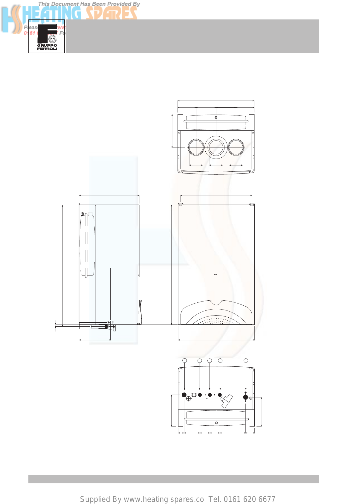
1.2 Dimensions and connections
Domina Plus F 24 E version
Top view
460
15012012070
110
10
725
Connections axis
Connections axis
100
270
720
80 80
80
175100
460
16025
Key
1 System delivery
2 Tap water outlet
3 Gas inlet
4 Tap water inlet
5 System return
4
100
1
2
Bottom view
1149560609536
4
3
5
Version - 09.2002
Page 5

Supplied By www.heating spares.co Tel. 0161 620 6677
DOMINA PLUS F 24 - 30 E
FERELLA EXTRA F 24 - 30 MEL
Ferella Extra F 24 MEL version
110
Top view
460
15012012070
10
725
Connections axis
Connections axis
100
270
720
80 80
80
175100
460
16025
Key
1 System delivery
2 Tap water outlet
3 Gas inlet
4 Tap water inlet
5 System return
Version - 09.2002
100
1
2
Bottom view
1149560609536
4
3
5
5
Page 6
Supplied By www.heating spares.co Tel. 0161 620 6677
DOMINA PLUS F 24 - 30 E
FERELLA EXTRA F 24 - 30 MEL
Domina Plus F 30 E version
200
Top view
460
120120110
110
14
733
Connections axis
420
80
8080
430362
189
1
Key
1 System delivery
2 Tap water outlet
3 Gas inlet
4 Tap water inlet
5 System return
189
36 95 60 60 155 54
6
460
23
4
Bottom view
5
175
Version - 09.2002
Page 7

Supplied By www.heating spares.co Tel. 0161 620 6677
DOMINA PLUS F 24 - 30 E
FERELLA EXTRA F 24 - 30 MEL
Ferella Extra F 30 MEL version
200
Top view
460
120120110
110
14
733
362
Connections axis
720
80
8080
430
189
Key
1 System delivery
2 Tap water outlet
3 Gas inlet
4 Tap water inlet
5 System return
Version - 09.2002
460
1
23
189
36 95 60 60 155 54
4
Bottom view
5
175
7
Page 8

Supplied By www.heating spares.co Tel. 0161 620 6677
DOMINA PLUS F 24 - 30 E
FERELLA EXTRA F 24 - 30 MEL
1.3 General view and main components
F 24 E/MEL version
29 43
187
5
28
90
132
49
34
81
8222
20
21
R4
3
4
2
1
5
0
6
114
OUT
R3
IN
MIN
R2
10 874 784 85 44
14 42 9 11
RESET
°C °C
R1
136
56
16
91
27
19
26
36
73
32
Key
5 Airtight chamber
7 Gas inlet
8 Tap water outlet
9 Tap water inlet
10 System delivery
11 System return
14 Safety valve
16 Fan
19 Combustion chamber
20 Burner assembly
21 Main nozzle
22 Burner
26 Combustion chamber insulation
27 Copper exchanger for heating and
tap water
28 Fume manifold
29 Fume outlet manifold
32 Heating circulator
34 Heating temp. sensor
36 Automatic air vent
42 Tap water temperature sensor
43 Air pressure switch
44 Gas valve
49 Safety thermostat
56 Expansion tank
63 Heating temperature setting
73 Antifreeze thermostat
74 System filler cock
81 Ignition electrode
82 Detection electrode
84 1st gas valve operator
85 2nd gas valve operator
90 Fume detection point
91 Air detection point
98 Off-On-Reset switch
114 Water pressure switch
132 Fume deflector
136 Flow meter
145 Water gauge
157 Tap water temperature setting
187 Fume diaphragm
R1-R2-R3-R4 Antifreeze heating elements
98 63 157
145
8
Version - 09.2002
Page 9

Supplied By www.heating spares.co Tel. 0161 620 6677
DOMINA PLUS F 24 - 30 E
FERELLA EXTRA F 24 - 30 MEL
F 30 E/MEL version
28
90
132
49
34
56
20
21
73
114
29 43187
Key
5 Airtight chamber
7 Gas inlet
8 Tap water outlet
5
16
91
27
9 Tap water inlet
10 System delivery
11 System return
14 Safety valve
16 Fan
19 Combustion chamber
20 Burner assembly
21 Main nozzle
22 Burner
26 Combustion chamber insulation
27 Copper exchanger for heating and
tap water
28 Fume manifold
19
818222
26
29 Fume outlet manifold
32 Heating circulator
34 Heating temp. sensor
36 Automatic air vent
42 Tap water temperature sensor
43 Air pressure switch
44 Gas valve
49 Safety thermostat
56 Expansion tank
36
63 Heating temperature setting
73 Antifreeze thermostat
74 System filler cock
81 Ignition electrode
R3
OUT
IN
MIN
R4
GRUNDFOS
32
82 Detection electrode
84 1st gas valve operator
85 2nd gas valve operator
90 Fume detection point
91 Air detection point
98 Off-On-Reset switch
R2
R1
114 Water pressure switch
132 Fume deflector
10 8 784 85 44
74
14 42 9 11
136
136 Flow meter
145 Water gauge
157 Tap water temperature setting
187 Fume diaphragm
RESET
°C °C
3
4
2
1
5
0
6
R1-R2-R3-R4 Antifreeze heating elements
98 63 157
145
Version - 09.2002
9
Page 10

Supplied By www.heating spares.co Tel. 0161 620 6677
FERELLA EXTRA F 24 - 30 MEL
1.4 Technical data table
DOMINA PLUS F 24 - 30 E
DOMINA PLUS - FERELLA EXTRA
Powers Pmax Pmin
Heating Power (Net Heat Value - Hi)
Useful Heating Power 80°C - 60°C
Tap Water Heating Power
Gas supply Pmax Pmin
Natural Gas main nozzles (G20) mm 12 x 1.30
Natural Gas supply pressure (G20) mbar 20.0
Pressure at Natural Gas burner (G20) mbar 11.8 2.5
Natural Gas delivery (G20) nm
LPG main nozzles (G31) mm 12 x 0.77
LPG supply pressure (G31) mbar 37.0
Pressure at LPG burner (G31) mbar 36.0 7.8
LPG delivery (G31) kg/h 2.00 0.89
Heating
Maximum working temperature in heating °C 90
Maximum working pressure in heating bar 3
Safety valve bar 3
Minimum working pressure in heating bar 0.8
Expansion tank capacity litres 7
Expansion tank pre-filling pressure bar 1
Boiler water content litres 0.8
Tap water
Maximum hot water production Dt 25°C l/min 13.6
Maximum hot water production Dt 30°C l/min 11.3
Maximum working pressure in hot water production bar 9
Minimum working pressure in hot water production bar 0.25
Hot water content litres 0.8
Dimensions, weights connections
Height mm 760
Width mm 460
Depth mm 272
Weight kg 38
Gas system connection inches 1/2
Heating system connections inches 3/4
Hot water circuit connections inches 1/2
Electrical power supply
Max electrical power absorbed W 125
Power voltage/frequency V/Hz 230/50
Electrical protection rating IP 44
kW 25.8 11.5
kcal/h 22,200 9,900
kW 23.8 9.7
kcal/h 20,400 8,300
kW 23.8 9.7
kcal/h 20,400 8,300
3
/h 2.73 1.22
24kW 30kW
Pmax Pmin
33.1 14.5
28,500 12,500
30.0 12.7
25,800 10,900
30.0 12.7
25,800 10,900
Pmax Pmin
16 x 1.25
20.0
13.0 2.5
3.50 1.53
16 x 0.75
37.0
35.5 7.0
2.60 1.14
90
3
3
0.8
10
1
1.5
17.2
14.3
9
0.25
0.8
760
460
363
48
1/2
3/4
1/2
125
230/50
44
10
Version - 09.2002
Page 11

Supplied By www.heating spares.co Tel. 0161 620 6677
DOMINA PLUS F 24 - 30 E
FERELLA EXTRA F 24 - 30 MEL
2. PRODUCT FRAMEWORK AND INTERNAL
COMPONENTS
2.1 Hydraulic circuit - heating
Hydraulic diagram for heating
When there is a call for heat, the room thermostat or control system make the burners ignite and the circulation
pump come into operation. The heat contained in the products of combustion is transferred to the water by the
system via the exchanger. For more details on the operating logic, refer to chap.3.
Key
29-187
16
49
34
27
82
20
73
5 Airtight chamber
-
+
5
R1
R2
43
7 Gas inlet
8 Tap water outlet
9 Tap water inlet
10 System delivery
11 System return
14 Safety valve
16 Fan
20 Burner assembly
27 Heat exchanger
29 Fume outlet collar
32 Heating circulator
56
34 Heating temperature sensor
42 Tap water temperature sensor
43 Air pressure switch
44 Gas valve
81
49 Safety thermostat
56 Expansion tank
73 Antifreeze thermostat
74 System filler cock
81 Ignition electrode
82 Detection electrode
114 Water pressure switch
136 Flow meter
44
187 Fume diaphragm
R1-R2-R3-R4 Antifreeze heating elements
42
114
14
74
Version - 09.2002
R3
8
7
R4
1110
9
32
136
11
Page 12

Supplied By www.heating spares.co Tel. 0161 620 6677
DOMINA PLUS F 24 - 30 E
FERELLA EXTRA F 24 - 30 MEL
Circulator (230v/50Hz)
Located on the heating circuit return, it is connected directly to the exchanger
via special forks and connected to the system via a threaded brass section. It has
three delivery/head levels (see diagram). Changing the delivery/head changes
the speed of the water flowing through the boiler exchanger and as a result the
temperature difference (DT) between heating delivery and return. Clearly,
increasing the delivery of the circulator decreases DT and vice versa. If it is not
used for a long time, the impeller might "jam" due to debris in the water. With the
front screw it is possible to access the impeller, which can be freed with the aid
of a screwdriver. The connection to the expansion tank and the air separator is
installed on the pump casing.
Checks
If the pump doesn't work:
· Check that the impeller is free to turn by turning the screw on the front with a
screwdriver.
· Check that both the card and the pump connection are powered.
· If there is no power supply, check the card.
· If there is power, change the pump.
Key
1 - 2 - 3 = Pump selector position
mC.A.
6
5.5
5
4.5
4
3.5
3
2.5
2
1.5
1
0.5
0
0 0.25 0.75 1.25 1.75 2.25 2.752.51.50.5 1 2 3
1
3
2
A
B
Air separator
This is used to expel the air in the heating circuit automatically. On boilers with
a twin heat exchanger, it is located on the pump casing. It is normally accessible
either via the fork or by simply unscrewing it from its seat.
A = Losses of head 24kW version
B = Losses of head 30kW version
3.2 3.4 3.6 3.8 4
3
m
/ h
12
Version - 09.2002
Page 13

Supplied By www.heating spares.co Tel. 0161 620 6677
DOMINA PLUS F 24 - 30 E
FERELLA EXTRA F 24 - 30 MEL
Expansion tank
It is connected to the pump casing via a pipe with a fork connection. On the 24kW version, it is located above
the pump, while on the 30kW version it is located behind the exchanger, inside the frame. The expansion tank
contains a diaphragm in contact, on one side, with the system water and, on the other side, with the air under
pressure (pre-loaded to 1 bar) inside the tank. By the expansion of the diaphragm and ensuing compression
of the air, the tank compensates for the thermal expansion of the water in the heating system.
Version 24kW
7 litre
Version 30kW
10 litre
Twin Heat Exchanger
The exchanger is a copper laminar assembly. It comprises a thickly finned portion, three circular pipes
containing the heating water and, inside them, another three pipes in the form of a spiral containing the tap water.
The heating water exchanges directly with the burnt gases, while the tap water does not have this kind of
exchange, it receives heat indirectly from the water in the three heating pipes. In this way, the surface of the
coil does not reach very high temperatures so less scale gets formed. In addition, being very small, it makes
the water speed very high over its entire section, making mineral deposits of any kind negligible. The typical
"omega" shape of the finning ensures an even distribution of the heat over all the finning, with consequent
benefits in terms of exchange efficiency and the life of the exchanger. A special surface treatment protects the
exchanger against oxidation and corrosion.
Version - 09.2002
13
Page 14

Supplied By www.heating spares.co Tel. 0161 620 6677
DOMINA PLUS F 24 - 30 E
FERELLA EXTRA F 24 - 30 MEL
Hydraulic unit
This is a single piece of brass to which the exchanger
delivery is connected for ease of access. It
accommodates a number of safety and adjustment
components.
The hydraulic unit includes:
- safety valve
- water pressure switch
- heating sensor
- filler cock
- tap water sensor
- tap water check valve
Water pressure switch
It ensures a minimum pressure for the system. It is normally open (NO) and
closes the contact when the pressure exceeds 0.5 bar. It works on low voltage.
Safety valve
It opens if the pressure exceeds 3 bars, making boiler operation safer and
protecting it against overpressure. You are strongly recommended not to use this
valve to drain the system; once open, dirt could remain inside it, preventing it from
closing completely.
Check valve
This is necessary to ensure no water returns from the heating system to the tap
water circuit.
Filler cock
This is located between the heating delivery and the tap water outlet. It is not fitted
on the boiler for some markets such as the British and Belgian ones.
14
Version - 09.2002
Page 15

Supplied By www.heating spares.co Tel. 0161 620 6677
DOMINA PLUS F 24 - 30 E
FERELLA EXTRA F 24 - 30 MEL
2.2 Hydraulic circuit - tap water
Hydraulic diagram for tap water
29-187
16
49
34
27
82
20
73
42
34
114
14
74
-
+
5
R1
R3
8
7
R4
9
R2
1110
43
Key
56
5 Airtight chamber
7 Gas inlet
8 Tap water outlet
9 Tap water inlet
81
10 System delivery
11 System return
14 Safety valve
16 Fan
20 Burner assembly
27 Heat exchanger
29 Fume outlet collar
32 Heating circulator
44
34 Heating temperature sensor
42 Tap water temperature sensor
43 Air pressure switch
44 Gas valve
49 Safety thermostat
56 Expansion tank
32
73 Antifreeze thermostat
74 System filler cock
136
81 Ignition electrode
82 Detection electrode
114 Water pressure switch
136 Flow meter
187 Fume diaphragm
R1-R2-R3-R4 Antifreeze heating elements
When the card receives a signal from the flow meter indicating a tap-water draw of over 2.5 l/min, the boiler starts
working normally for tap water. If heating was in operation, or the pump was anyhow working, the boiler will in
any case give priority to the tap water, stopping the pump. The tap water does not exchange directly with the
products of combustion, but via the heating water in the exchanger, avoiding sudden changes in temperature.
The boiler is equipped with 4 heating elements and an antifreeze thermostat in order to protect the tap water
pipes if the temperature drops under 6°C. The heating elements heat the pipes up to a temperature of 15°C
measured by the thermostat.
Version - 09.2002
15
Page 16

Supplied By www.heating spares.co Tel. 0161 620 6677
DOMINA PLUS F 24 - 30 E
FERELLA EXTRA F 24 - 30 MEL
Flow meter
Located at the cold water inlet, its task is to provide the card with a signal at a
frequency (7 Hz per litre) in direct proportion to the tap-water flow rate. It is
composed of a body (stator) and a rotor inside it. There is a filter on its inlet to
prevent foreign bodies damaging it. It should be remembered that to turn on the
boiler for tap-water operation, the tap-water pressure must be at least 0.25 bars
and the draw flow rate must be greater than 2.5 l/min.
Check
To check it works properly, you need to make sure the flow rate is at least
2.5 l/min and then test the signal to the electric card with a frequency meter. This
makes it possible to understand whether the problem lies with the flow meter,
incorrect contacts, or the card.
Flow-rate restrictor
This is a diaphragm downstream from the flow meter. Its task is to limit the tapwater flow rate; the boiler modulates its capacity to keep the tap-water
temperature set by the user, but since the boiler capacity is limited to its rated
capacity, it is necessary to limit the tap-water flow rate to obtain high
24 kW version
30kW version
65
60
55
*
m
50
T.
31
30
29
28
27
26
25
24
23
22
21
20
19
18
17
16
15
14
13
12
11
10
kcal/h
x1000
45
Tap water delivery temperature °C
40
39
Tap water inlet temp. 15°C
0 345678910111213141516
Tap-water flow rate dm /min
3
16
In this case, above the flowrate limit m, even though the
*
boiler is working at its rated
capacity, it is not able to
Exchanged boiler capacity
17
18
maintain the set temperature
of 50°C
Version - 09.2002
Page 17

Supplied By www.heating spares.co Tel. 0161 620 6677
FERELLA EXTRA F 24 - 30 MEL
2.3 Gas circuit
Gas circuit diagram
DOMINA PLUS F 24 - 30 E
29-187
16
49
34
27
82
20
73
42
34
114
14
74
-
+
5
R1
R3
8
7
R4
9
R2
1110
43
Key
56
5 Airtight chamber
7 Gas inlet
8 Tap water outlet
9 Tap water inlet
81
10 System delivery
11 System return
14 Safety valve
16 Fan
20 Burner assembly
27 Heat exchanger
29 Fume outlet collar
32 Heating circulator
44
34 Heating temperature sensor
42 Tap water temperature sensor
43 Air pressure switch
44 Gas valve
49 Safety thermostat
56 Expansion tank
32
73 Antifreeze thermostat
136
74 System filler cock
81 Ignition electrode
82 Detection electrode
114 Water pressure switch
136 Flow meter
187 Fume diaphragm
R1-R2-R3-R4 Antifreeze heating elements
Version - 09.2002
17
Page 18

Supplied By www.heating spares.co Tel. 0161 620 6677
DOMINA PLUS F 24 - 30 E
FERELLA EXTRA F 24 - 30 MEL
Gas valve
It supplies gas to the nozzles between a minimum and maximum pressure. For
the valve to work correctly, it is necessary for the pressure upstream from it to
be stable and suited to the type of gas being used, while the valve will supply a
regular pressure to the nozzles. The gas valve contains two operators. The
function of the first one is to open or close, while the task of the second one is
to modulate the capacity according to the system's requirements. The signal
comes from the card and is in the form of continuous voltage. The first operator
receives fixed voltage that may be between 80 and 110V DC, for the second
operator the voltage will vary between 25 and 54V DC according to the need of
the main card.
Checks
If the valve doesn't work:
· The only possible check is to see whether gas comes out of the screw "B" at
the rated pressure when setting the boiler on "test" with the boiler at full power
(see "Test Functions" chap. 3.1).
B
IN OUT
25±50V DC
COMMON
80±110V DC
Modulation
The control system governs its boiler capacity so as to keep the delivery temperature constant in accordance
with the settings on the control panel. The nozzle gas pressure is modulated by the valve and specifically via
the 2nd operator. The card provides a change in continuous voltage (between 25 and 54 V DC ) according to the
difference between the delivery temperature and the set point.
Checks
Modulation can be checked in three ways:
· Visually, by checking the flame.
· Using a pressure gauge to check the gas pressure downstream from the valve.
· Checking the voltage on the card (X6, 3/4) that should vary between 25 and 55V
Note that with very low pressure upstream from the valve, opening the valve may be slow and the boiler
could shut down due to failed ignition.
DC.
18
Version - 09.2002
Page 19

Supplied By www.heating spares.co Tel. 0161 620 6677
DOMINA PLUS F 24 - 30 E
FERELLA EXTRA F 24 - 30 MEL
Adjusting burner pressure
Since this unit has flame modulation, there are two fixed pressure settings: the minimum and maximum, which
must be as stated in the technical data chart according to the type of gas.
· Connect a suitable pressure gauge to pressure point "B"
downstream from the gas valve.
· Disconnect the pressure compensation tube "F" .
· Take off the protective cap "C".
· Run the boiler in TEST mode (pressing RESET 3 times
consecutively within 5 sec.).
· Set knob 2 on minimum.
· Adjust the minimum pressure with the screw "D", clockwise to
decrease it and anticlockwise to increase it.
· Set knob 2 on maximum (clockwise).
· Adjust the maximum pressure with the screw "E", clockwise to
increase it and anticlockwise to decrease it.
· Reconnect the pressure compensation tube "F".
· Put the protection screw "C" back in.
F
C
N.B. The test lasts 5 minutes. It is advisable to open 1 or 2 taps to
get rid of the excess capacity.
After checking or
adjusting the pressure,
it is mandatory to seal the
adjustment screw with paint or
a specific seal.
35
30
24 kW version
30kW version
mbar
25
20
G31
LPG
E
B
IN OUT
A
D
25±50V DC
COMMON
80±110V DC
Key
A Pressure point upstream
B Pressure point downstream
C Protection screw
D Minimum pressure adjustment screw
E Maximum pressure adjustment screw
F Pressure compensation tube
15
10
5
kW
9101112 13 14 15 16 17
8
18 19 20 21 22 23
Version - 09.2002
G20
Nat. Gas
24 25 26 27 28 29 30 31 32 33 34
19
Page 20

Supplied By www.heating spares.co Tel. 0161 620 6677
DOMINA PLUS F 24 - 30 E
FERELLA EXTRA F 24 - 30 MEL
Gas supply conversion
The unit can function with either Natural Gas or LPG and is factory-set for use with one of the two gases, as
clearly shown on the packing and on the unit's dataplate. Whenever a different gas to that for which the unit
is preset has to be used, a conversion kit will be required, proceeding as follows:
1 Replace the nozzles at the main burner, inserting
the nozzles specified in the technical data
table, according to the type of gas used.
2 Using the remote control, edit parameter 3 of
the boiler parameter menu.
3 Adjust the burner minimum and maximum
pressures, setting the values given in the
technical data chart for the type of gas used.
4 Apply the sticker, contained in the conversion
kit, near the dataplate as proof of the conversion.
20
Version - 09.2002
Page 21

Supplied By www.heating spares.co Tel. 0161 620 6677
DOMINA PLUS F 24 - 30 E
FERELLA EXTRA F 24 - 30 MEL
2.4 Burner unit
Operation
The burner unit comprises a manifold and 12/16 nozzles (depending on the capacity), the burner mount,
electrodes and the burner assembly.
Manifold - nozzles
The valve sends gas at a suitable pressure to the manifold, which homogeneously
distributes the gas to the single burner stages at the nozzles. It is secured
directly to the burner mount. Its positioning must be exact since it affects the air/
gas mixture. In addition, the threaded holes forming the seat of the nozzles must
be aligned with the respective Venturi tube of the burner. If it were not so, the air/
gas mixture would be wrong and there would be poor combustion with an unstable
flame. The nozzles are made of brass and machined extremely precisely for their
dimensions. There is a seal between the nozzles and the manifold.
Ignition electrode
The ignition electrode is made of a metal alloy (Kanthal) that withstands high
temperatures and oxidation. Its base is composed of a ceramic composite of
glazed alumina whose purpose is to protect and electrically insulate it. Once the
ignition procedure begins, the card powers the electrode with a pulsating voltage
of a few kV, a series of electrical discharges is set off between the electrode and
the head of the burner (set at a distance of 3.5 mm). Clearly, these sparks are
the trigger for the air-gas mixture. It is important for the distance between the
electrode and the burner head to be 3¸ 4 mm and the discharge to be made at
the centre.
Checks
If there is no discharge:
· Check whether the boiler shuts down, in which case check the
connection of the electrode to the card or whether it discharges at
other points; if necessary, check the safety thermostat and the card.
· If the boiler does not shut down and the fan keeps on working,
check the air pressure switch.
· If there is a discharge, but no ignition and after 10 seconds the
boiler shuts down, check the gas valve and, if necessary, the
card.
· If there is a discharge and then a flame, but the boiler still shuts
down after 10 seconds, check the detection electrode and its
connection.
±0.5
3.5
Version - 09.2002
21
Page 22

Supplied By www.heating spares.co Tel. 0161 620 6677
DOMINA PLUS F 24 - 30 E
FERELLA EXTRA F 24 - 30 MEL
Detection electrode
Made of the same material as the ignition electrode, it is set 11 mm from the
burner head. Combustion causes the flame atmosphere to ionize, making it
conductive. Thanks to the mass of the burner, making a suitable potential with
the electrode produces a flow of direct current on it. For our cards, it is
necessary to have an ionizing current of at least 5 µA to detect a flame. A
signal is normally obtained ranging from 10 to 40µA (see chap. 3.1).
Burner assembly
The burner assembly is composed of 12 or 16 burner stages. Each stage is composed of two pressed steel
half bearings, with a suitably cut stainless steel head. Gas enters at the bottom of the stage. Thanks to the
special Venturi-tube shape of the bottom portion of the stage, the gas "injected" by the nozzle carries with it
the primary air needed for combustion. The air-gas mixture thus formed inside the stage is evenly distributed
on the burner head. Combustion takes place homogeneously over the entire length of the single stages, with
the contribution of the secondary air from the bottom of the burner mount and from the combustion chamber
itself. The set of stages in operation forms a single belt of flame, light blue in colour, whose size varies according
to the nozzle gas pressure, that is the boiler capacity modulation.
22
Version - 09.2002
Page 23

Supplied By www.heating spares.co Tel. 0161 620 6677
DOMINA PLUS F 24 - 30 E
FERELLA EXTRA F 24 - 30 MEL
2.5 Fume circuit
Fume deflector and manifold
All forced-flow boilers have a fume deflector above the exchanger whose main
task is to make the secondary air crossing the burners uniform, making the flame
homogeneous and stable. The fumes then reach a fume manifold whose job is
to make them move on to the fan.
Airtight chamber
Its task is to isolate the products of combustion from the area surrounding the
boiler. The airtight chamber contains all the components involved in the fume
routing. The wires and pipes coming out of its lower portion are insulated with
silicone seals, while its upper portion is fitted for hooking up with the flues. The
cover is sealed off with a porous plate and is fitted with two plugs for using a probe
to analyse the fumes and combustion air.
Fan and pressure switch points
Powered at 230V/50Hz by the card (X11 - 1/2), the fan has
the job of expelling the products of combustion from the fume
chamber. A plate is normally placed above the exchanger to
act as a deflector, make the incoming air from the bottom of
the burner uniform, make the flame stable and obtain the
required air/gas ratio. In order to make sure the fan works
properly, there are two pressure points inside it. The first one
detects a "static" pressure signal that is positive, the second
one detects a "dynamic" pressure signal via an appropriate
"Venturi tube", which is negative. With the difference in
pressure detected by the two test points it is possible to
check whether the fumes are adequately evacuated.
Version - 09.2002
23
Page 24

Supplied By www.heating spares.co Tel. 0161 620 6677
DOMINA PLUS F 24 - 30 E
FERELLA EXTRA F 24 - 30 MEL
Air pressure switch
This is used to check whether the fumes are adequately evacuated. The pressure switch compares the static
and dynamic signals coming from the pressure test points on the fan according to the figure. The pressure switch
is connected to the card and is normally open (see diagram). Before the card initiates the ignition procedure
(opening the valve, etc.), you must make sure that the fan works properly and that the air pressure switch
ensures this by closing its contacts. This happens if the difference in pressure is 165±15Pa. So the signal must
be at least 180Pa. To open its contacts again, the difference in pressure must drop under 150±13Pa. To perform
checks on contact opening and closing, it is always recommended to check directly on the card (X5 - 3/4).
Checks
It is necessary to check:
· Whether the electrical connections are correct.
· Whether the pressure test point pipes are clean and contain no condensation water.
· That the signal is open when the fan is not working.
· That the pressure is at least 180Pa and that above this pressure the pressure switch closes its contacts.
· If the signal is low, it is necessary to check that the fume diaphragm is correct, the fan has 230V, the pressure
test points are properly inserted and the Venturi tube has no burrs of any kind. Lastly, check that the ends
of the pipes are not obstructed.
N.B. The pressure difference must be measured with the airtight chamber closed. The pressure gauge
connections can come out through the hole, which is closed by a silicone plug, on the front of the cover.
C
NC
NO
Key
NO = Normally open
NC = Closed
C=Common
Pressure
gauge
pa
24
Version - 09.2002
Page 25

Supplied By www.heating spares.co Tel. 0161 620 6677
DOMINA PLUS F 24 - 30 E
Pipe length
calculated in
linear metres
Diaphragm
to use
45 mm
47 mm
50 mm
No diaph.
Min
0 m
13 m
23 m
38 m
Max
13 m
23 m
38 m
48 m
F 24
F 30
47 mm
50 mm
52 mm
No diaph.
Diaphragm
to use
Min
0 m
20 m
35 m
45 m
Max
20 m
35 m
45 m
50 m
Pipe length
calculated in
linear metres
FERELLA EXTRA F 24 - 30 MEL
Fume ducts
The unit is "type C" with an airtight chamber and forced draught, the air inlet and fume outlet must be connected
to one of the following extraction/suction systems. With the aid of the tables and methods of calculation
indicated, before commencing installation, it is first necessary to check that the fume ducts do not exceed the
maximum permissible lengths. The current standards and local regulations must be observed.
This C-type unit must be installed using the fume exhaust and suction ducts supplied by FERROLI
S.p.A. in accordance with UNI-CIG 7129/92. Failure to use them automatically forfeits all warranty and
liability of FERROLI S.p.A.
Diaphragms
Boiler operation requires fitting the diaphragms supplied with the unit as instructed in the following tables. As
the resistance of the fume ducts changes, the diaphragms make it possible to keep the combustion parameters
(CO2, etc.) within the optimum operating range. Note that with low-resistance fume ducts, a high-resistance
diaphragm (small hole diameter) is used and vice versa.
Choosing the diaphragm using coaxial
pipes
Diaphragm
Type
Coaxial
60/100
Coaxial
80/125
Length up to:
1 bend + 1 metre
1 bend + 3 metres
1 bend + 3 metres
1 bend + 4 metres
1 bend + 5 metres
to use
F 24
50 mm
No diaph.
45 mm
50 mm
No diaph.
F 30
52 mm
No diaph.
50 mm
No diaph.
No diaph.
Changing the diaphragm
If inserting or changing a diaphragm, it is necessary to
remove the fan assembly, take out the fume coupling 1 and
insert the required diaphragm 2.
N.B.:
The diameter
of the hole Ø
is stamped
on the
diaphragm
Ø
Choosing the diaphragm using
separate pipes
.
1
Boilers are fitted as
standard with the
smallest diaphragm in
the series.
Before inserting the fume outlet pipe, it is therefore
necessary to check there is the right diaphragm
Version - 09.2002
(when it is to be used) and that it is correctly
positioned.
.
2
25
Page 26

Supplied By www.heating spares.co Tel. 0161 620 6677
DOMINA PLUS F 24 - 30 E
FERELLA EXTRA F 24 - 30 MEL
Calculation example
Here we give an example of the calculation for a separate fume
outlet. We recommend inserting a condensate trap on long
vertical sections to prevent condensation getting onto the
burner and damaging it. If monitoring the condensate trap is
not guaranteed, it must be fitted with a suitable drain pipe and
air trap, which in its turn must be appropriately connected to
a suitable drain.
6
Ref.
1
2
3
4
5
6
No. Pieces
1
1
1
1
36
1
Description
Air bend Ø80
Horizontal air pipe Ø80
Windproof end piece
Condensate collection cup coupling
Vertical fume pipe Ø80
Outlet flue + coupling
Total
5
4
1 2 3
Equivalent
loss
1.5 m
1.0 m
2.0 m
3.0 m
36.0 m
4,0 m
47.5 m
26
Version - 09.2002
Page 27

Supplied By www.heating spares.co Tel. 0161 620 6677
DOMINA PLUS F 24 - 30 E
FERELLA EXTRA F 24 - 30 MEL
2.6 Electrical circuit
Electrical terminal board
Follow the instructions given in the figure to access the electrical connection terminal board.
The layout of the terminals for the various connections is given in the wiring diagram.
81 82
Wiring diagram
Key
16 Fan
32 Heating circulator
34 Heating temperature sensor
42 Tap water temperature sensor
43 Air pressure switch
49 Safety thermostat
72 Room thermostat (not supplied)
73 Antifreeze thermostat
N.B. Respect the phase and neutral connections
R4
2314
MV3
MV4
R1 R2 R3
73
X1
X2
44
MV1
MV2
X6
X8
16
32
X3
X11
12
81 Ignition electrode
82 Detection electrode
114 Water pressure switch
136 Flow meter
138 External sensor (not supplied)
139 Remote control (not supplied)
X9
X12
1223811212
X5
230V ~
50Hz
NL
72
139
138
N
L
12 11 10 9 8 7 6 5 4 3 2 1
34
43
42 114
49
1234567
136
-+
X4
12345678910111213
MF05FD
X7
Version - 09.2002
27
Page 28

Supplied By www.heating spares.co Tel. 0161 620 6677
DOMINA PLUS F 24 - 30 E
FERELLA EXTRA F 24 - 30 MEL
Main electronic card
The electronic card is a Honeywell DMF05FD: part of the card works on low
voltage (24V) and the remainder on 230V (see diagram). It is fitted with a fuse
(2A). There are loads and controls common to the card that have already been
described, such as:
· Pump
· Fan
· Gas valve
· Air pressure switch
There remain some components described hereunder.
Ignition + detection electrode, see chap. 2.4 Burner Unit
28
Version - 09.2002
Page 29

Supplied By www.heating spares.co Tel. 0161 620 6677
DOMINA PLUS F 24 - 30 E
FERELLA EXTRA F 24 - 30 MEL
Safety thermostat
X5 - 1/2 has a thermostat with gold contacts that opens if the temperature
exceeds 100°C. Connected directly to the main card, when it opens it cuts off
the power supply to the valve directly, shutting down the boiler. It is set on the
left-hand side of the exchanger by a spring.
Heating and tap water temperature probe
These are NTC sensors that increase their resistance as the temperature
decreases and are connected directly to the main card X4 - 24V (heating 12-13,
tap water 10-11). The heating sensor performs the antifreeze function too.
Temperature ( C° )
100
90
80
70
60
50
40
30
25
15
5
Resistance ( k Ohm )
0,68
0,92
1,25
1,7
2,5
3,6
5,3
8
10
15,6
25,3
NTC sensor
33
30
27
24
21
18
15
12
Resistance ( k Ohm )
9
6
3
0
0 20 40 60 80 100 120
Temperature ( C° )
Version - 09.2002
29
Page 30

Supplied By www.heating spares.co Tel. 0161 620 6677
3. OPERATION
3.1 Operating principle.
The boiler is designed to function with two types of gas: Natural Gas or LPG. It works with systems on the
cutting edge of technology as it uses sophisticated software with a double processor governing the
modulation, power, control and safety equipment. On powering up the boiler from the mains for the first time,
the display will show in succession: 88.-LO-14-HI-06-EO-14 that represent the software release of the
processor for low (LO) and high (HI) voltage and the memories (EO). Lastly, the boiler will go onto stand-by,
with LED 5 on and the delivery temperature on the display.
When there is a call for heating, the circulator and fan start working; then the air pressure switch enables the
control and safety unit to ignite the burner. Via the electronic flame modulation system, the boiler capacity
is gradually metered till it reaches the set delivery temperature. If the power needed for the heating plant is
lower than the minimum boiler power, when the delivery temperature exceeds the setting of 6°C, the burner
switches off and the electronic system enables re-ignition only after another 2 minutes. On reaching the set
ambient temperature (room thermostat), the burner switches off and the circulator keeps on working for
another 6 minutes to enable better heat distribution throughout the system. If the remote control (Ferroli) is
used, the system will try to modulate the ambient temperature according to the setting. In this passage the
remote control can lower the delivery temperature under the setting to maintain the ambient temperature: in
any case, if the ambient temperature exceeds the remote control setting by 1°C the burner switches off and
the circulator stays on for post-circulation.
If hot tap water is drawn off during the heating phase, the electrical heating circuit automatically turns off and
the hot tap water production circuit switches on.
Throughout this phase the heating system circulator stops and the boiler delivers water at the set temperature.
The boiler keeps the tap water temperature constant by means of flame modulation, even when different
quantities are drawn off.
Diagnosis characteristics: the boiler shows the type of trouble directly on the display with an identification
code.
Slow ignition for heating
The power in the ignition phase (10s) is 50% (adjustable) and the increase in temperature is gradual
(10°C/minute - adjustable from 1 to 20°C).
Circulator anti-locking
If not used for 24 h, the heating circulator is turned on for a few seconds to prevent it locking due to an extended
stoppage.
Antifreeze protection
With the heating temperature sensor, if the temperature falls under 5°C, the boiler starts working normally
to then switch off when the temperature exceeds 15°C, and the circulator keeps on working for another
6 minutes. This protection is active even if the boiler is switched off from the control panel.
Tap water circuit antifreeze protection
It is possible to ensure antifreeze protection for the tap water circuit with the 4 heating elements of 10W - 230V
connected to terminal X2 of the control unit. The antifreeze thermostat is connected in series with the heating
elements. The protection is activated when the temperature falls under 5°C and it turns off above 15°C.
DOMINA PLUS F 24 - 30 E
FERELLA EXTRA F 24 - 30 MEL
30
Version - 09.2002
Page 31

Supplied By www.heating spares.co Tel. 0161 620 6677
DOMINA PLUS F 24 - 30 E
FERELLA EXTRA F 24 - 30 MEL
Test operation
"Test" operation makes it possible to turn on the boiler in heating mode, but with idle time, flame modulation
and tap water operation turned off. It is possible to turn on "test" operation from the control panel on the boiler
by pressi
power. Operating knob 2, the display will blink and you can modify the heating power that will change instantly.
The power shown on the display will vary from 0 to 99. (100%) indicating the percentage change between the
minimum and maximum heating power. In the same way, with knob 3 you can change the ignition power that
will be set immediately. Pressing
operation can also be used to adjust the gas valve and to analyse the fumes.
N.B. To clear the boiler power during "Test" operation we recommend opening 1 or 2 taps.
Ionization current display
During "test" operation it is possible to display the ionization current. Pressing on the display will show the
3 times in 5 seconds. In this phase (5 min) LED 1 will blink and the display will show the heating
three times in 5 seconds quits the Test function (see power adj.). Test
ionization current in µA that is measured instantly. If you press
be shown. The ionization current can vary from 10 to 40µA (depending on the power). Under 5µA the flame is
not detected by the control card.
a second time, the heating power will again
Version - 09.2002
31
Page 32

Supplied By www.heating spares.co Tel. 0161 620 6677
FERELLA EXTRA F 24 - 30 MEL
3.2 Operating diagram
DOMINA PLUS F 24 - 30 E
SUMMER (tap water)
Hot water taps closed
Boiler on "SUMMER"
WINTER (heating)
SUMMER (tap water)
Hot water taps closed
Hot water taps closed
Flow meter off
Boiler on "SUMMER"
Heating delay of 2 min. performed
Boiler on
System pressure > 0.8 bar
Electrical power supply on card 230V
Boiler on stand-by "LED 5 ON"
Fuse OK
Room thermostat, heating potentiometer on call
System pressure >0.8 bar
Heating required "LED 4 ON"
Boiler on stand-by "LED 5 ON"
Heating circulator comes on
Hot water tap opens 2.5 l/min
Flow meter enabling signal
Hot tap water required "LED 3 ON"
Heating and tap water sensor enabling signal (NTC 10 Kohm at 25°C)
Air pressure switch "NO" contact open, fan starts
Intake and outlet ducts open, resistance under table limit.
Pressure difference at air pressure switch >180 Pascal (18.00 mm approx.)
Air pressure switch "NO" contact closed
100°C safety thermostat enabling signal
Electric discharge to ignition electrode
Continuous voltage of 230V to the gas valve operators
Main burner ignition
Flame detection at ionization electrode within 10 sec. (safety time)
End of electric discharge.
Ionization working range
- 1 micro Ampere minimum for safety
- 2/3 micro Ampere minimum for working
Ignition gas adjustment (natural gas or LPG) with appropriate parameter.
Heating temperature adjustment trips; burner and
Closing hot water tap, switching off burner.
fan switch off.
End of requirement for hot tap water
The circulator is working "LED 4 blinking" according
"LED 3 OFF"
to the dedicated parameter.
Stand-by after hot tap water operation
At the end of the 2 min delay, the burner re-ignites
"LED 4 blinking"
when required.
Delay before starting heating of 2 min.
Room thermostat trips on reaching the set
temperature.
Boiler in post-circulation "LED 4 blinking"
Heating circulator operates for 6 min.
(post-circulation).
Boiler on
Electrical power supply on card 230V
Fuse OK
System pressure >0.8 bar
Boiler on stand-by "LED 5 ON"
Hot water tap opens 2.5 l/min
Hot water taps closed
Flow meter off
Heating delay of 2 min. performed
System pressure > 0.8 bar
Boiler on stand-by "LED 5 ON"
Room thermostat, heating potentiometer on call
Heating required "LED 4 ON"
Heating circulator comes on
Flow meter enabling signal
Hot tap water required "LED 3 ON"
Heating and tap water sensor enabling signal (NTC 10 Kohm at 25°C)
Air pressure switch "NO" contact open, fan starts
Intake and outlet ducts open, resistance under table limit.
Pressure difference at air pressure switch >180 Pascal (18.00 mm approx.)
Air pressure switch "NO" contact closed
100°C safety thermostat enabling signal
Electric discharge to ignition electrode
Continuous voltage of 230V to the gas valve operators
Main burner ignition
Flame detection at ionization electrode within 10 sec. (safety time)
End of electric discharge.
Ionization working range
- 1 micro Ampere minimum for safety
- 2/3 micro Ampere minimum for working
Ignition gas adjustment (natural gas or LPG) with appropriate parameter.
WINTER (heating)
Closing hot water tap, switching off burner.
End of requirement for hot tap water
"LED 3 OFF"
Stand-by after hot tap water operation
"LED 4 blinking"
Delay before starting heating of 2 min.
Heating temperature adjustment trips; burner and
fan switch off.
The circulator is working "LED 4 blinking" according
to the dedicated parameter.
At the end of the 2 min delay, the burner re-ignites
when required.
Room thermostat trips on reaching the set
temperature.
Boiler in post-circulation "LED 4 blinking"
Heating circulator operates for 6 min.
(post-circulation).
32
Version - 09.2002
Page 33

Supplied By www.heating spares.co Tel. 0161 620 6677
DOMINA PLUS F 24 - 30 E
12 4 3
5
RESET
°C °C
FERELLA EXTRA F 24 - 30 MEL
3.3 Control panel
Description of controls
The control panel is composed of 1 key, two
knobs and 2 displays.
When the key is pressed, there is a beep in
confirmation.
Key
1 ON-OFF / RESET / TEST
Pressing the key
Holding the
protection stays on). To turn it back on, press the
resets boiler operation after a shutdown.
key down for at least 5 sec. turns off the boiler. In this period, LED 5 blinks slowly (antifreeze
key again for at least 5 sec. and the boiler will reset
and display the software and memories.
Pressing the
key 3 times within 5 sec. automatically takes you to TEST operation (see Test
operation).
2 Setting system temperature / selecting Summer-Winter
Knob 2 is used to adjust the heating temperature and switch over between Summer/Winter (see
"adjustments" 3.4). It is necessary to set the heating temperature with the remote control if it is connected
on the boiler.
3 Hot water temperature setting
Use knob 3 to adjust the hot tap water temperature (see adjustments 3.4). It is necessary to set the tap
water temperature with the remote control if it is connected on the boiler.
4 Operating display
Indicates the boiler operating temperature on heating or hot water production, a flame (point at bottom lit
up) or any trouble.
5 Operating LED
LED
1
Burner on indicator (on steady)
Boiler in Test mode (blinking)
Shutdown indicator (steady light) Press RESET + code on the display
2
Shutdown fault indicator (blinking light) + code on the display
Hot water required (steady light)
3
Standby for heating after tap water operation
(blinking light)
Heating required (steady light)
4
Standby for heating after heating operation
(blinking light)
Electrical power supply
5
12345
Steady: boiler on
Blinking: boiler off but electric
power supplied
Version - 09.2002
33
Page 34

Supplied By www.heating spares.co Tel. 0161 620 6677
DOMINA PLUS F 24 - 30 E
FERELLA EXTRA F 24 - 30 MEL
Information on the display
During normal operation, the boiler diagnostics control sends information on the state of the boiler and measures
the temperature of the water. This information is automatically shown on the display according to the type of
operation.
Operation LED on
Standby
Heating
Tap water
Standby for heating op.
(after tap water op.)
Standby for heating op.
(after heating op.)
Fault 1
(restore operation by pressing Reset)
Fault 2
(restore operation by removing fault)
L5
L5, L4 + L1
L5, L3 + L1
L5, L4 blinking
L5, L4 blinking
L5, L2
L5, L2 blinking
Display
Heating temp. (for example 40°C)
Heating temp. (for example 60°C)
Tap water temp. (for example 50°C)
Tap water temp. (for example 60°C)
Heating temp. (for example 70°C)
For example 1 (blinking display)
For example 37 (blinking display)
34
Version - 09.2002
Page 35

Supplied By www.heating spares.co Tel. 0161 620 6677
DOMINA PLUS F 24 - 30 E
FERELLA EXTRA F 24 - 30 MEL
3.4 Adjustments
Room temperature adjustment
Using the room thermostat, set the temperature desired in the rooms. Controlled by the room thermostat, the
boiler lights and heats the system water to the set system delivery setpoint temperature. The generator turns
off when the desired temperature in the rooms is reached. If the remote control (Ferroli) is used, the system
tries to modulate the ambient temperature according to the setting. In this passage the remote control can lower
the delivery temperature under the setting to maintain the ambient temperature: in any case, if the ambient
temperature exceeds the setting by 1°C the burner switches off and the circulator stays on for post-circulation.
The boiler also works with an external temperature sensor (see "sliding temperature"). If the room thermostat
or the remote control are not installed the boiler will keep the system at the set system delivery setpoint
temperature.
Summer/Winter selection
For the Summer/Winter selection, use knob 2 (see "control panel").
Turning it onto
position the heating temperature shown on the display will be 20 °C. In "Summer" mode the antifreeze function
stays on.
Turning it onto
(Summer) turns off the heating function. Only the hot tap water production is active. In this
(Winter) with a minimum temperature of 30°C turns on both heating and hot tap water.
Heating temperature setting
To set the system delivery temperature, turn the specific knob.
It can vary from a minimum of 30°C to a maximum of 85°C; however, it is advisable not to operate the boiler below
45°C (return temperature). Turning the knob sets the required temperature (clockwise to increase, anticlockwise
to decrease) that is shown on the display. During the setting, the display quickly blinks and once defined it stops
blinking after 2 sec. and goes back to showing the actual operating temperature.
If connecting to a remote timer control (optional), the system temperature is only governed with the remote
control. By turning the heating temperature control knob on the boiler, the temperature can only be displayed
and not changed.
Adjustment LED on Temperature on the display
System temperature
L5, L4
30 - 85 °C
Version - 09.2002
35
Page 36

Supplied By www.heating spares.co Tel. 0161 620 6677
DOMINA PLUS F 24 - 30 E
FERELLA EXTRA F 24 - 30 MEL
Hot water temperature adjustment
To set the system delivery temperature, turn the specific knob.
It can vary from a minimum of 30°C to a maximum of 65°C. Turning the knob sets the required temperature
(clockwise to increase, anticlockwise to decrease) that is shown on the display. During the setting, the display
quickly blinks and once defined it stops blinking after 2 sec. and goes back to showing the actual operating
temperature.
Adjustment LED on Temperature on the display
L5, L3Tap water temperature 40 - 65 °C
boiler, the temperature can only be displayed and not changed.
Adjusting the maximum heating output
To adjust the heating power, set the boiler on TEST operation (see "Test operation"). During the ignition phase,
the display shows the ignition power and, immediately afterwards, the heating power. Turn the heating
temperature control knob clockwise to increase the power or anticlockwise to decrease it. The display shows
Adjustment LED on
Heating system power
- knob 2 -
L1, L4, L1
blinking
set on the control panel, also with the remote control connected the system must be free of any errors.
Temperature on the display
0-100%
(Voltage at the valve to
change the power)
If connecting to a remote timer control
(optional), the system temperature
is only governed with the remote
control. By turning the tap water
temperature control knob on the
a percentage ranging from 0 to 100%
(the display blinks during the setting).
The figure shown on the display
indicates the percentage change
between the boiler's minimum and
maximum power. This adjustment is
Ignition power adjustment
To adjust the ignition power, set the boiler on TEST operation (see "Test operation"). During the ignition phase,
the display shows the ignition power and, immediately afterwards, the heating power. Turn the tap water
temperature control knob clockwise to increase the ignition power or anticlockwise to decrease it. The display
shows a percentage ranging from 0
Adjustment (TEST mode on) LED on
Ignition power
- knob 3 -
L1, L4, L1
blinking
Display
0-100%
(Voltage at the valve to
change the power)
to 100% (the display blinks during
the setting). The figure shown on the
display indicates the percentage
change between the boiler's
minimum and maximum power. This adjustment is set on the control panel, also with the remote control
connected.
Adjusting the heating t by changing the delivery-head of the circulator
The temperature drop t (difference in temperature of the heating water between the system delivery and return)
must be less than 20°C and this is obtained by changing the delivery-head of the circulator with its speed
changer (or with the switch).
36
Version - 09.2002
Page 37

Supplied By www.heating spares.co Tel. 0161 620 6677
DOMINA PLUS F 24 - 30 E
System delivery temperature °C
Outside temperature °C
20 10 0 -10 -20
90
80
70
60
50
40
30
20
1
2
3
4
57610 9 8
85
FERELLA EXTRA F 24 - 30 MEL
Sliding Temperature
When the optional outside sensor is installed the boiler adjustment system can work with "Sliding
Temperature." In this mode, the temperature of the heating system is governed according to the weather
conditions outside so as to ensure a high degree of comfort and energy savings throughout the year. In particular,
as the outside temperature increases the system delivery temperature decreases according to a specific
"compensation curve." With the Sliding Temperature adjustment, the temperature set becomes the maximum
system delivery temperature. It is recommended to set a maximum value to permit system adjustment
throughout its useful working range. The compensation curve can be modified with the knobs 2 and 3 (see
"control panel"). Turning knob 2 (see "control panel") and at the same time keeping the RESET key pressed
adjusts the compensation curve; whereas, turning knob 3 (see "control panel") and at the same time keeping
the RESET key pressed adjusts the parallel movement of the curves. To be able to make these adjustments
the boiler must be on standby (only
Adjustment LED on Display
L5Compensation curve - knob 2 0 - 10
L5Parallel shift of the curves (knob 3) 20 - 40 °C
LED 5 on). If you do not set the
compensation curve, leaving it on "0",
the boiler cannot work in "sliding
temperature" mode.
Compensation curves
Example of parallel curve shift
90
85
80
70
60
50
40
30
System delivery temperature °C
20
20 10 0 -10 -20
Outside temperature °C
710 9 8 6
90
85
80
70
60
50
40
30
System delivery temperature °C
20
5
4
3
2
1
9
10 8
20 10 0 -10 -20
Outside temperature °C
7
6
5
4
3
2
1
Version - 09.2002
If the boiler is hooked up with the optional remote control, the above adjustments (system temperature,
hot water temperature, compensation curve) can be made solely with the remote control. The user menu
on the boiler panel is disabled and functions solely as a display. In addition, the remote control will
always have priority for varying the delivery temperature to keep the room temperature at the required
level.
37
Page 38

Supplied By www.heating spares.co Tel. 0161 620 6677
DOMINA PLUS F 24 - 30 E
FERELLA EXTRA F 24 - 30 MEL
3.5 Operating parameter adjustment
Boiler parameter adjustment
These parameters can only be adjusted with the remote control connected on the card.
Copy day
Days
Change time
Programming
cursor
Heating operation
COPY
DAY
-
DAY/
PROGRAM
AUTO
MANUAL
DAY
1...7
+
d
Hot tap
water operation
1234567
12:00
Days Display
AUTO
MAN
0
C
27.
TEMP
123456
PROGRAM
Power level
Program
Antifreeze operation
/TEMP
Information /
RESET
Holidays
Change
temperature
Cursor
Program
selection
Simultaneously pressing keys 1 and 3 on the "PROGRAM" keypad for longer than 2 seconds brings up the
boiler parameter menu on the remote control screen.
On then pressing
settings.
The change is immediately active on leaving the menu.
38
you can scroll through the parameters, and with the and skeys you can edit the
i
0
1
Position
Tap water control selection
0 = Instantaneous production with twin heat
exchanger
1 = Production with external boiler
(not applicable)
Version - 09.2002
Page 39

Supplied By www.heating spares.co Tel. 0161 620 6677
DOMINA PLUS F 24 - 30 E
FERELLA EXTRA F 24 - 30 MEL
0
This parameter makes it possible to keep the timer-thermostat functions of the remote control even with zone
systems. The sliding temperature adjustment is set and controlled via the boiler control panel and the main card.
The remote control loses its room modulation function.
If the boiler is used without the remote control the boiler operation corresponds to selecting 1. But it will not
be necessary to set the value to 1.
0
2
3
Position
Selection of modulating timer-thermostat/
timer-thermosat On/Off for zone systems
0 = Modulating
1 = On/Off zone systems
Position
Natural gas / LPG selection
0 = Natural gas
1 = LPG
0
Selecting the "post-circulation" parameter, after a call for heating, the pump continues to work for the postcirculation time (6 min.).
Whereas, selecting "continuous pump," after a call for heating, the pump works constantly.
The pump is always turned off during tap water operation.
6
4
5
Position
Pump post-circulation / pump continuous
operation selection
0 = Post-circulation
1 = Continuous pump
Position
Post-circulation time adjustment.
Setting: 6min.
(range 1 to 255 min.)
Version - 09.2002
39
Page 40

Supplied By www.heating spares.co Tel. 0161 620 6677
DOMINA PLUS F 24 - 30 E
FERELLA EXTRA F 24 - 30 MEL
10
This permits changing the speed of increasing the delivery temperature.
100
Indicates the percentage difference between the minimum and maximum boiler power.
6
7
Position
System delivery temperature increase
adjustment. Setting: 10°C/min.
(range 1 to 20°C/min.)
Position
Heating power adjustment.
Setting: 100%
(range 0 to 100%.)
2
120
50
8
9
10
Position
Adjustment of idle time after switching off
heating.
Setting: 2 min.
(range 0 to 10 min.)
Position
Adjustment of idle time after tap water
operation
Setting: 120 sec.
(range 0 to 255 sec.)
Position
Adjustment of power during ignition phase.
Setting: 50%
(range 0 to 100%.)
Indicates the percentage difference between the minimum and maximum boiler power.
40
Version - 09.2002
Page 41

Supplied By www.heating spares.co Tel. 0161 620 6677
DOMINA PLUS F 24 - 30 E
FERELLA EXTRA F 24 - 30 MEL
0
30
Used to make a parallel shift of the compensation curve.
To quit the menu, press keys 1 and 3 simultaneously or wait to quit automatically after 1 minute.
11
12
Position
Compensation curve selection.
Setting: 0 (adjustment turned off)
(range 1 to 10)
Position
Compensation curve fixed point adjustment
Setting: 30
(range 20 to 40)
Version - 09.2002
41
Page 42

Supplied By www.heating spares.co Tel. 0161 620 6677
DOMINA PLUS F 24 - 30 E
FERELLA EXTRA F 24 - 30 MEL
Checking operating data log
With a remote control installed, pressing keys 1 and 2 simultaneously for longer than 2 seconds takes you
to the operating data log menu.
Storing the last 8 faults.
The display on the remote control shows the storage sequence of the faults and their code
Error
F
Position
code
F011
F33 2
F37 3
F06 3
F015
F016
F09 7
F39 8
By pressing the
Position 1 indicates the last fault that occurred. When there is a fault, this is saved at point 1 , while the ones
already saved are moved on by one place.
key you can scroll through the numbers of the faults.
i
42
Version - 09.2002
Page 43

Supplied By www.heating spares.co Tel. 0161 620 6677
DOMINA PLUS F 24 - 30 E
Fault Possible cause
Heating sensor fault Sensor damaged
Incorrect wiring
(short-circuit)
Heating sensor fault Sensor damaged
Incorrect wiring
(broken)
Tap water sensor fault Sensor damaged
Incorrect wiring
(short-circuit)
Display
Tap water sensor fault Sensor damaged
Incorrect wiring
(broken)
Mains voltage The mains voltage is
under 185 VAC
Mains frequency The frequency exceeds the
tolerance of +/- 5%
Card trouble Defective hardware
Low system pressure System empty
Water pressure switch not
connected or damaged
RESET key jammed ON/OFF button
damaged
External sensor fault Damaged sensor
Sensor wiring
shorted
FERELLA EXTRA F 24 - 30 MEL
4. Unit self-diagnosis
Fault Diagnosis
The boiler is equipped with an advanced self-diagnosis system. In the event of trouble with the boiler, the display
will show the fault code. There are faults that in order to restore operation it suffices to press RESET
the boiler fails to start, it is necessary to resolve the fault indicated by the operating LEDs (faults from 1 to 25);
other faults cause temporary shutdowns that are automatically reset as soon as the value comes back within
the boiler's normal working range (faults from 30 to 39). When the boiler starts functioning normally again, the
display stops blinking and the fault code disappears.
; if
LED
Steady light
steady light
Blinking light
steady light
List::
Fault Possible cause
Display
No burner ignition No gas
Safety thermostat trips Damaged thermostat
Air pressure switch (with
contacts closed before
turning on the fan)
Air pressure switch (fails to
close the contacts within
60 sec. of turning on the fan)
Fault CureDISPLAY
Boiler shutdown
Low system pressure
Detection or ignition
electrode fault
Defective gas valve
No water circulation in the
system
Air pressure switch contact
closed
Incorrect wiring to the air
pressure switch
Air pressure switch contact
open
Incorrect wiring to the air
pressure switch
Wrong diaphragm
Flue not correctly sized
Make sure that the gas cocks ahead of the boiler and on the
meter are open.
Press button 1 "Reset".
In case of repeated shutdowns, contact the nearest assistance
centre
Fill the system to 1-1.5 bar cold by means of the specific cock
located in the boiler.
Close the cock after use.
Air pressure switch (closes
and opens the contacts
5 times within 60 sec. of
the ignition phase)
Fault on the flame control
circuit
No burner ignition Incorrect gas valve
Card trouble Interference caused by the
From
to
Wrong diaphragm
Flue not correctly sized
Interference caused by
the electric mains
Card microprocessor
damaged
connection
Broken wiring of gas valve
electric mains
Card microprocessor
damaged
Version - 09.2002
43
Page 44

Supplied By www.heating spares.co Tel. 0161 620 6677
37047 SAN BONIFACIO - VR - ITALY
tel. 045/6139411 - tlx 480172
fax 045/6100233-6100933
code 354M011/0
 Loading...