


Manual
Professional 32 x 32-channel AD/DA Converter
Version 1.2

Introduction
Thank you for choosing the A32 as your new A/D D/A converter!
The A32 is an A/D-D/A converter with 32 analog inputs and outputs,
64x64 MADI and 32x32 ADAT digital channels.
Furthermore, it is possible to route internally between all I/O channels
and even create submixes, which can be monitored using the
headphones output on the front of the A32.
Four TFT screens show all analog input and output levels at the same
time and allow perfect visualization of all the A32’s settings.
The intuitive one knob operation together with the integrated help
system makes using the A32 a breeze.
We’re sure that our A32 will become a valuable part of your studio.
Software and Updates
For more information concerning updates and support please visit our
website: www.ferrofish.com
Operation
1
A32 operation
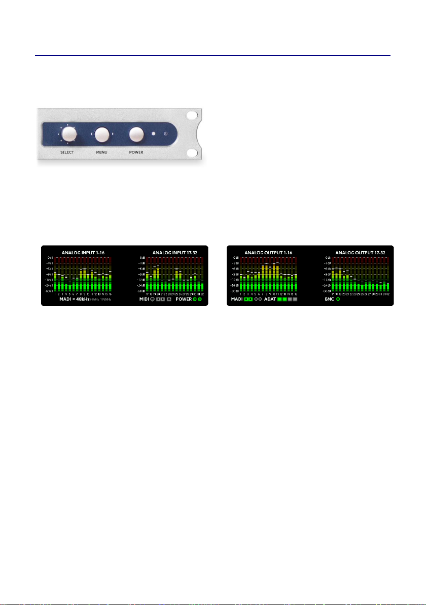
The A32 can be fully controlled from the front panel by using the
SELECT wheel and the MENU button. The POWER button can be used
as a home button and for
switching the unit on and off. It is
also possible to control the A32
via USB, MIDI or MIDI-overMADI.
The main screen shows the levels of all 32 analog inputs and outputs as
well as other important status information, so that you always know
what is happening. You can always return to this screen with a short
press of the power button.
The status line beneath the meters shows the following (from left to
right):
The current synchronization source and sample frequency
Whether there is MIDI input from the MIDI plugs, from MIDI-
over-MADI and/or from USB
If power is attached to the left and/or right mains input
Any audio input present on optical MADI, coax MADI and/or
ADAT 1-4. The symbol will be yellow if only audio is received
and green if the input is also synchronous to the sample
frequency
If BNC wordclock input is present
When using an external wordclock source (MADI, ADAT, or BNC), the
corresponding icon shows a blinking pulse symbol.
Operation
2
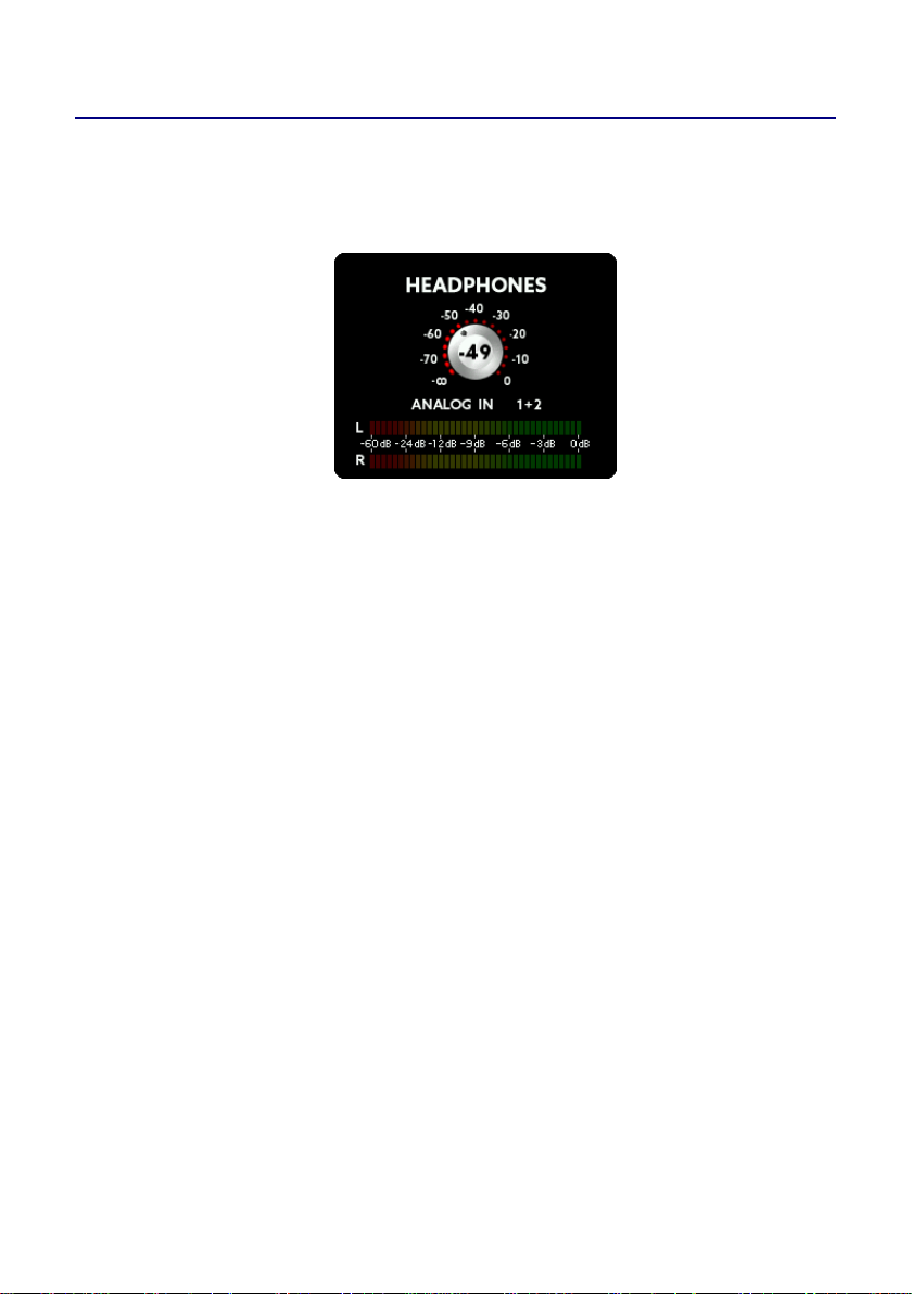
Headphones
Turning the SELECT knob whilst the main screen is visible on the
display will make the headphones menu appear. You can now select
the volume of the headphones output:
By pressing the MENU key, you can also select and then change the
following:
Source: You can choose between ANALOG IN / OUT, MADI IN /
OUT, ADAT IN / OUT and MIX 1-7.
Channel: Once you have chosen a source you can then select
the specific channel(s) to be monitored. Cycling thru the
channels will let you first select mono channels, followed by
stereo channel pairs.
If you prefer to have a full mix of the channels, you can choose a mix
preset. For further information regarding mix presets please see the
MIX chapter.

Operation
3
main menu
Pressing the MENU key shows the main menu. Use the SELECT wheel
to choose the desired menu option and press MENU to activate it.
The main menu has the following functions:
CLOCK
Here you can set the A32 to generate the wordclock itself (master) or
listen to a wordclock signal (slave) from an external source. If choosing
Master you can also select the sample rate here.
MIX
You can select, load and edit one of seven mixer presets in this menu.
The preset mixes can be used for the headphones output.
DIGITAL
Here you can see the analog I/O’s as meters and all digital I/O’s as LED
dots. This means that every dot shows a digital channel, which changes
color according to the level of the signal.
SETUP
Setup lets you change the gain-levels of the analog inputs and outputs.
Additionally, you can define the routing of the A32, set the MIDI and
MADI processing, change global settings or lock the front panel.
DSP
In the DSP menu optional DSP plugins can be loaded and edited.
PRESET
Levels, gains and the routing of the A32 can be saved and loaded in up
to six different preset slots.
HELP
You can change the language of the help system here, get information
about the schematic structure and lookup the firmware version.

Operation
4
main menu – CLOCK
The CLOCK SOURCE menu lets you select the wordclock source and the
sample frequency of the A32 when running in Master Mode:
The numbers below the labels show the internally generated clock as
Master or the measured external sample rate. If no sample rate is
detected, „---“ will be displayed.
MASTER
By selecting MASTER as the clock source, the internal clock generator
will be used for the wordclock. This circuit consists of a high precision
temperature compensated oscillator, which can be set to the desired
frequency.
MADI, ADAT
If you set the clock source to MADI or ADAT, the A32 extracts the
wordclock signal from these digital inputs, reduces jitter using the
digital PLL circuit and routes it back to the BNC output. The A32 then
uses this clock signal. When using higher sample frequencies, the MADI
and ADAT interfaces employ SMUX modes, in this case you will need to
set the desired SMUX frequency manually. Please see the SMUX
chapter for more details.
BNC
When receiving an external wordclock via the BNC IN of the A32, the
wordclock signal will also be routed thru the jitter reduction stage
before using it.

Operation
5
SMUX operation
Internally the A32 always uses all 32 analog channels, but the number
of digital MADI and ADAT channels is limited in relation to the SMUX
mode currently in use.
SMUX/1
SMUX/1 offers frequencies from 32kHz up to 48kHz.
SMUX/2
When using higher frequencies (64kHz to 96kHz) SMUX/2 is used. This
means that a single channel of audio is split across two consecutive
channels of the digital stream when transmitted via ADAT or MADI
(signal multiplexing). Consequently, the number of ADAT or MADI
channels is halved. For example, when using a sample rate of 96kHz
there will be 32 channels available via MADI as opposed to the usual
64 channels at 48kHz and below. Likewise, at 96kHz each ADAT cable
will carry 4 channels as opposed to 8 at 48kHz and below.
SMUX/1 and SMUX/2 offer redundant MADI. This means, that when
the MADI signal is lost, the A32 automatically switches to the other
MADI input.
SMUX/4
The SMUX/4 operation (128kHz-192kHz) divides the information of
each channel across four channels. This reduces the bandwidth of the
digital channels by a factor of 4. ADAT is not supported at that speed
and is switched off. The MADI cable only offers 16 channels at
SMUX/4. In order to still be capable of transferring all 32 analog
channels a special SMUX/4 mode will be activated. This mode uses
both MADI coax and optical connections simultaneously to transfer all
32 channels:
optical MADI: transmits and receives analog channels 1-16
coax MADI: transmits and receives analog channels 17-32
Operation
6
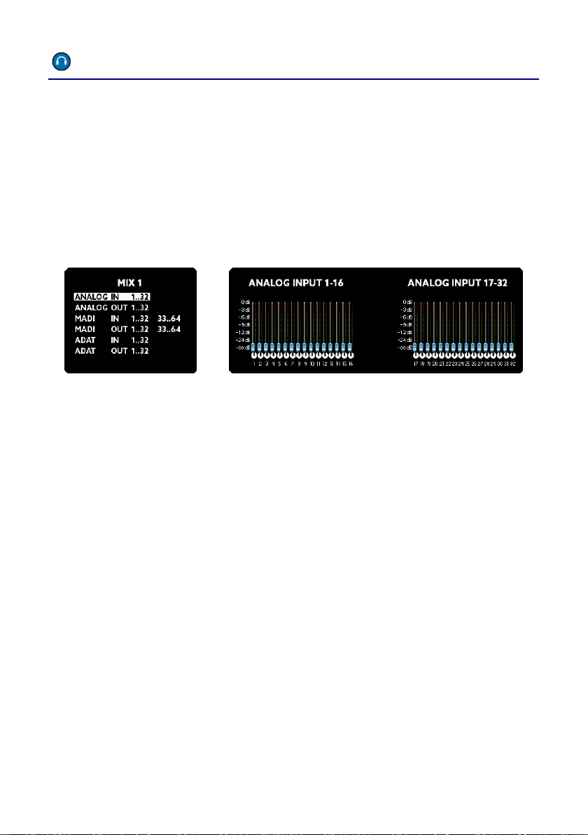
main menu – MIX
Inside the MIX menu you can select one of seven mix presets. The A32
allows you to create a custom mix of all analog and digital I/O’s which
can then be sent to the stereo headphones output on the front panel.
You can choose between these mix presets within the headphones
screen by selecting MIX 1 to 7 as the source.
In the MIX screen, after selecting the number of the MIX preset, press
MENU to edit:
First, select one of the eight groups. The actual mix of channels from
within this group will now be visible on the right screens. Press the
MENU button to edit the mix in three steps:
Select the channels: Scroll to select either a single channel or
group of multiple channels (2, 4, or 8). Continue by pressing
MENU.
Now you can adjust the level. When it is set as desired, press
MENU again.
Finally set the pan. If you selected two or more channels, the
even numbered pan knobs move in the opposite direction to
the rotation of the SELECT wheel.
These steps you can repeat as desired. When finished, hold down
the MENU button for a few seconds. All changes will be stored and
won’t get lost even when switching the unit off and on.

Operation
7
main menu – DIGITAL
The DIGITAL menu shows all analog and digital inputs and outputs. All
digital inputs and outputs are shown as dots with a traffic light color
code.
In this way, you have an overview of all channels at a glance.
The traffic light LED colors have the following meaning:
Hold down the MENU button for a few seconds to get back to the
previous screen.
Color
Range
red
-3dBFS to 0dBFS
yellow
-15dBFS to -4dBFS
green
-59dBFS to -16dBFS
grey
-inf to -60dBFS

Operation
8
main menu – SETUP -> GAINS
The analog inputs of the A32 can be set to different sensitivities. You
can choose between three reference levels: +4dBu, +13dBu and
+20dBu. Using the DSP, you can additionally set the reference levels
from -8dBu to +20dBu in 1 dB steps. The DSP always calculates the
optimum configuration. For example, if you set +12dBu, the analog
reference will be set to +13dBu and the signal will be amplified by 1dB,
because it is only 12dBu.
The number on top of the fader shows the maximum dBu level, which
the input is able to handle. When the fader is set to 20, as in the
picture above, the input can handle a maximum input level of +20dBu.
Avoid exceeding this maximum level to prevent digital clipping.
In addition, you can see the levels of the analog inputs and so easily set
the correct gain. The dB scale of these levels is found on the right hand
side of the screens.
The minimum value -8dBu corresponds
(approximately) to the reference level of -10dBV used
by consumer devices, like CD-players for example.

Operation
9
main menu – SETUP -> LEVELS
The LEVELS screen is similar to the GAINS screen described on the
previous page and is responsible for the levels of the analog outputs.
As with the inputs, you can set the level of each channel in 1dB steps
from -8dBu to +20dBu. The A32 offers individual analog level switching
of +4dBu, +13dBu and +20dBu. This means that this level is reached
when the digital output reaches 0dBFS.
If you select one of the three reference levels exactly, the digital signal
will be converted 1:1 to analog. However, if you select a value in
between these reference levels, the DSP will calculate the optimal
combination between analog and digital levelling. For example, if you
select +12dBu the analog output will be switched to +13dBu and the
digital signal will be attenuated by 1dB to reach the +12dBu output
level.
Just like the inputs you can also meter the levels of the channels here.
Please note, the level of the outputs will not change when adjusting
the amplification here, because you see the digital level before digital
and analog amplification.

Operation
10
main menu – SETUP -> ROUTING
The A32 features a sophisticated routing matrix. In the ROUTING
screen you can see a graphical representation on the left side and a list
view on the right screen.
To change the routing, do the following:
Choose the output: Turn the SELECT rotary to highlight a block
of 8 outputs. It corresponds to a column on the graphical view
and a line on the list view.
Choose the input: Press MENU. You will now be able to connect
an input to the chosen output by turning the SELECT rotary. The
inputs are shown as rows in the graphical view or as text on the
left hand side of the list view line.
Hold down the MENU button for a few seconds to leave the routing
screen.

Operation
11
main menu – SETUP -> MADI
The A32 has two MADI formats (one optical and one coaxial) which can
be used in a very flexible way:
1 - optical
The A32 only uses the optical MADI
input. No automatic switching between
the formats will happen.
2 - optical
The A32 uses the optical MADI input.
When the signal is lost, the A32 switches
to coax MADI. It will only switch back to
optical if the coax signal is subsequently
removed.
3 - optical
Same function as 2. In addition, both
inputs are scanned constantly and if no
signal is present on one a warning will be
shown on the main screen.
4 – coax
The A32 only uses the coax MADI input.
No automatic switching between the
formats will happen.
5 – coax
The A32 uses the coax MADI input.
When the signal is lost, the A32 switches
to optical MADI. It will only switch back
to coax if the optical signal is
subsequently removed.
6 – coax
Same function as 5. In addition, both
inputs are scanned constantly and if no
signal is present on one a warning will be
shown on the main screen.

Operation
12
main menu – SETUP -> MIDI
The MIDI routing screen is intended to allow you to choose the way
MIDI data is routed between MIDI and MIDI over MADI:
1 - separate
MIDI-over-MADI and MIDI are separated.
Control messages for the A32 are
scanned from both input ports and
replies are sent back to the
corresponding output port.
2 – MADI
priority
MIDI-over-MADI and MIDI are
connected: Data from the MIDI-overMADI port is sent to MIDI, and MIDI
input is sent back to MIDI-over-MADI.
The A32 receives and sends control
messages from/to the MIDI-over-MADI
port.
This way you can convert between MIDIover-MADI and MIDI while the A32
listens to the MIDI-over-MADI port.
3 – MIDI
priority
MIDI-over-MADI and MIDI are
connected: Data from the MIDI-overMADI port is sent to MIDI, and MIDI
input is sent back to MIDI-over-MADI.
The A32 receives and sends control
messages from/to the MIDI port.
This way you can convert between MIDIover-MADI and MIDI while the A32
listens to the MIDI port.

Operation
13
main menu – SETUP -> SETTINGS
In the SETTINGS screen you can switch some global features:
BNC Termination
The wordclock of the A32 is terminated internally with a 75-ohm
resistor by default. When daisy chaining wordclock of several units,
you should leave this option set to ON. If you’re using T-connectors for
the connections set this option to OFF, because in this case only the
last unit in the chain should be terminated.
MADI 96k Frame
There are two MADI transfer standards for the SMUX/2 mode (64kHz –
96kHz):
48k Frame: Identical to SMUX/1. The signal of 1 channel is split
(multiplexed) across a pair of 2 channels in order to double the
bandwidth. The usual 64 MADI channels are therefore reduced
to 32 channels.
96k Frame: The MADI stream is natively reduced to 32 channels
by increasing the frame size and allowing channels to be
transmitted directly.
Both formats transfer the same number of channels (32). The
advantage of the 96k frame mode is that the receiver can distinguish
between SMUX/1 and SMUX/2 mode automatically and can switch
appropriately. Please ensure both units have the same setting.

Operation
14
MADI short frame
Using the full bandwidth of MADI you can transfer 64 (SMUX/2: 32,
SMUX/4: 16) channels. By setting MADI short frame, the A32 will only
transfer 56 (SMUX/2: 28, SMUX/4: 14) channels. This setting
corresponds to an early MADI specification, which is capable of using
the remaining bandwidth for varispeed. Nowadays varispeed is not
commonly used in favor of having the full 64 channels.
Redundant Power
When using two power supplies for redundancy reasons, please set
this menu option to ON. If switched on, the A32 monitors both PSU
inputs. In case of a failure of one power supply, the A32 will display a
warning message on the main screen.
ADAT 4 as S/PDIF
The fourth ADAT I/O port can be configured as a stereo S/PDIF port. If
the sample rate of the connected device differs from the sample rate
of the A32, the external sample rate will be converted to that of the
A32 using a sample rate converter (SRC). The stereo S/PDIF input will
be distributed on the ADAT 4 channels, the stereo output is sourced by
the first two ADAT 4 channels.
Keyclick
This setting switches the key click sound on or off.
Delay compensation
If you daisy-chain two A32 using MADI, MADI data for the second A32
needs to pass through the first A32 first. This introduces a small delay
by design.

Operation
15
To compensate this delay, you should indicate the position of the A32
in the chain using this option:
Single: only 1 unit attached to MADI
1 of 2: first of two attached units
2 of 2: second of two attached units.

Operation
16
main menu – SETUP -> LOCK
To prevent accidental or forbidden operation of the A32, you can lock
the front panel. The headphone screen is still accessible, but all other
functions are locked. To lock the A32 front panel, enter the PIN
number printed on the bottom of the unit:
After entering the correct number, hold down the MENU button for a
few seconds to activate the lock.
To unlock the A32, repeat the procedure: Enter the correct number
and hold down the MENU button for a few seconds.
The PIN number of each A32 is fixed and can’t be changed by the user.
IMPORTANT: Keep the PIN code in a safe place!
Reconstruction of a PIN code by the manufacturer is
subject to a fee.

Operation
17
main menu – DSP
The Sharc DSP built into the A32 is used for routing, mixing and
gain/level settings.
But the DSP can do much more audio processing:
Using the USB connection, you can install Ferrofish-DSP plugins, which
are able to process audio effects with high accuracy and without
latency.
You can find more information on our website: www.ferrofish.com
Remark: You can’t use plugins from other manufacturers, esp. VST and
Scope plugins.

Operation
18
main menu – PRESET
The A32’s GAINS, LEVELS and the routing can be permanently stored in
one of six preset slots. This lets you pre configure the A32 and saves
you time later by just recalling the presets.
The PRESET Menu lets you choose which preset to load:
After selecting the number of the preset to load, you can choose which
parts of the preset you want to load: Gains of the analog inputs and/or
levels of the analog outputs and/or routing.
To store a preset, please use the store option :
Here you can store the settings using one of the six preset slots.

Operation
19
main menu – HELP
The HELP screen shows you the schematic structure of the A32, you
can look up the firmware version and you can set the language of the
help system.
The A32 provides a help system, which explains all key sections of the
unit, to guide you through using the A32 without even consulting the
manual.

A32 inputs and outputs
20
A32 inputs and outputs – analog: D-Sub25
All analog inputs and outputs are fully balanced and can send or
receive levels of +4dBu, +13dBu or +20dBu. Each channel can be set
independently. You can also set levels between these three reference
levels, which will be achieved digitally using the DSP. If setting the
input and output levels exactly to one of the three reference levels,
there is no digital gain calculation by the DSP.
D-Sub25 connectors are used for the analog inputs and outputs. The
pin configuration corresponds to the TASCAM® standard.
When connecting an unbalanced device to the A32’s input, please
connect the inverting (cold) input channel to ground.
When connecting an unbalanced device to the A32’s output, please
leave the inverting (cold) output channel open (not connected).
Please note that unlike analog systems, digital systems
do not have any soft clipping zone. When converting
analog signals, leave sufficient headroom to avoid
digital distortion.

A32 inputs and outputs
21
A32 inputs and outputs – MADI
MADI is a professional audio format, which can transfer 64 channels
over a distance of up to 2 kilometers.
When connecting several MADI devices in series you need to put them
in a daisy chain. This means that you connect the output of the first
device to the input of the second device and so on. This way you can
connect two units to transfer 64 analog inputs and 64 outputs.
The A32 has an optical and a coaxial MADI port. Both ports can be
used simultaneously for redundancy purposes. When using the
SMUX/4 mode, each port transfers only 16 channels, so both ports will
be used to transfer all 32 analog channels.
Use either optical fiber cables (SC connectors) or coaxial cable with an
impedance of 75 ohms (BNC connectors) for MADI.
Both kinds of cabling have their own advantages and disadvantages.
Due to optical transmission, fiber cables cannot be influenced by
electromagnetic crosstalk and can be used for distances up to 2 km.
Ferrofish also offers a single mode MADI version of the A32 on
request, which lets you transfer audio signals up to 10km. Please
contact us for more information.
Keep in mind that an optical fiber may break if bent too much.
Coaxial cables with an impedance of 75 ohms are widely used and easy
to source. Unless using armored optical fiber they are more robust, but
are limited to a length of 100 meters.

A32 inputs and outputs
22
When using sample rates higher than 48kHz, channels have to be
bundled to transport that higher data rate. As a result, the maximum
amount of usable channels is reduced according to the following chart:
The original MADI standard utilized a maximum channel count of 56
channels instead of 64 channels (numbers in brackets). This lower
channel count allows the sample rate to vary by +/- 10%. Nowadays
the variable sample rate is not commonly used anymore, in favor of
having more usable channels.
In SMUX/4 Mode both MADI connections (optical and coax) will be
used together to overcome the channel limitation of the MADI
standard and transfer all 32 analog inputs and outputs at up to 192kHz.
In this case the first 16 channels are transferred using the optical port
and the remaining 16 channels via the coax port.
The A32 detects automatically if 64 or 56 channels are received. The
number of channels it outputs can be set by using the MADI short
frame switch.
frequency
MADI channels
32kHz, 44.1kHz, 48kHz (SMUX/1)
64 (56) channels
64kHz, 88.2kHz, 96kHz (SMUX/2)
32 (28) channels
128kHz, 176.4kHz, 192kHz (SMUX/4)
16 (14) channels
128kHz, 176.4kHz, 192kHz (SMUX/4)
A32: 32 channels

A32 inputs and outputs
23
A32 inputs and outputs – ADAT
ADAT is a very common digital multichannel interface standard
invented by Alesis. It is capable of transferring eight channels of audio
at up to 48kHz over an optical plastic fiber cable. The maximum length
of an ADAT connection is limited to 10 meters.
When using ADAT with sample rates higher than 48kHz, the channel
count halves in SMUX/2 mode.
The A32 has four ADAT pairs, capable of transferring 32 channels in
SMUX/1 mode. The ports with the white door are the ADAT outputs,
the ports with the black door are the inputs.
The ADAT ports are switched off when using the SMUX/4 mode.
frequency
A32 ADAT channels
32kHz, 44.1kHz, 48kHz (SMUX/1)
8 channels x 4 I/O
64kHz, 88.2kHz, 96kHz (SMUX/2)
4 channels x 4 I/O

A32 inputs and outputs
24
A32 inputs and outputs – BNC WORDCLOCK
Every digital audio system needs a wordclock frequency to work. This
clock frequency can either be generated by the system itself (master
mode) or it can be supplied externally (slave mode). There can be only
one master clock in a digital system, all other connected devices must
slave to this clock.
The A32 can generate its own clock or it can synchronize to an external
clock.
For external synchronization the A32 can use the wordclock embedded
in the MADI or ADAT data stream. Alternatively, you can connect an
external wordclock directly using the BNC IN port.
Use the CLOCK screen to define where the wordclock should be
obtained from, or if the A32 should generate the wordclock itself.
Please note, that the BNC-IN wordclock must be terminated by
75-ohms (see SETTINGS), except when you’re using T-connectors for all
units.
The BNC OUT port always outputs the refreshed wordclock used by the
A32.

A32 inputs and outputs
25
A32 inputs and outputs – USB and MIDI
USB
The USB port can be used to remote control the A32. When connecting
to the PC, the A32 will appear as a USB-MIDI device.
Also, USB will be used to flash new firmware to the A32. Please visit
our website to check for a new firmware version.
MIDI
It’s also possible to use the MIDI input and MIDI output ports for
remote control.
An advantage of the MIDI connection is the galvanic isolation, because
the MIDI input has an opto coupler. Also, it’s easy to daisy chain
multiple A32 using MIDI to remote control more than one unit at the
same time.
Another feature is that MIDI data from the MIDI port can be
embedded into the MADI stream and vice versa. Use the MIDI screen
to configure the routing of the MIDI data.

Remote Software
26
Remote Software
Please note: The remote software is not available at the time of
printing this manual. Please visit our website for more information.
The A32 can be controlled from a computer via this software. To do so,
select one option to connect the PC with the A32:
USB Interface
Connect the A32 using a USB cable with your PC. A USB-MIDI driver will
be installed automatically, then the connection will be established.
MIDI Interface
Use a MIDI Interface to connect the A32 with your PC.
MADI Interface (MIDI over MADI)
You can also use the MADI connection to transfer MIDI. In this case,
MIDI will be embedded in the MADI data stream. To use this feature,
you need to have a MADI card which is capable of embedding MIDI
data. Please check the documentation of your MADI card to find out if
it supports this feature or contact the card manufacturer.
After starting the program, first select the input and output MIDI port
of the A32 and press connect. All scanned A32’s will then be shown in a
list.
Now simply select an A32 to work with and you’re ready to remote
control it.
Please visit our website to download the software and for more
information: www.ferrofish.com

technical specifications
27
technical specifications
MADI I/O: optical + coaxial interface
64 channels @32kHz, 44.1kHz, 48kHz
32 channels @64kHz, 88.2kHz, 96kHz
32 channels @128kHz, 176.4kHz, 192kHz*
* both interfaces work independent to achieve full 32+32 channels
MIDI over MADI implemented
latency: 3 samples
automatic switching between optical <-> coax MADI when signal lost
ADAT I/O: 4+4 x optical interfaces
32 channels @32kHz, 44.1kHz, 48kHz
16 channels @64kHz, 88.2kHz, 96kHz
n/a @128kHz, 176.4kHz, 192kHz
latency: 3 samples
S/PDIF: ADAT 4 I/O can be reconfigured as S/PDIF
input has sample rate converter included (performance of SRC: -128dB)
output follows A32 sample frequency
Wordclock: BNC: 1 x input, 1 x output
75 Ohm Termination switchable for input
MIDI I/O: two DIN5 jacks, for remote
conversion MIDI <-> MIDI over MADI possible
A/D Converter: 4 x CS5368 (Cirrus Logic)
4 x DSub25 / Tascam
analog switches: +20dBu, +13dBu, +4dBu
digital gain: +20dBu...-8dBu, 1dB steps
latency: @48kHz: 12/fs, 0.25ms, @96kHz: 9/fs, 0.09ms,
@192kHz: 5/fs, 0.03ms
OpAmps: RC4580 + OPA1664
level indicator: TFT screen, 28 levels
D/A Converter: 4 x CS4365 (Cirrus Logic)
4 x DSub25 / Tascam
analog switches: +20dBu, +13dBu, +4dBu
digital gain: +20dBu...-8dBu, 1dB steps
latency: @48kHz: 7.8/fs, 0.16ms, @96kHz: 5.4/fs, 0.06ms,
@192kHz: 6.6/fs, 0.03ms
OpAmps: RC4580 + OPA1664
level indicator: TFT screen, 28 levels
USB: USB 2.0 (remote, update)

CE/FCC, RohS, WEEE
28
Headphone: independent stereo channel
select any mono or stereo source
select one of 5 mixes of all inputs and outputs
digital volume control
audio processor: Sharc DSP ADSP-21489 / 400MHz
Routing of all 128+128 channels
Mixing to headphone output
DSP plugins
PLL: digitally controlled PLL / Jitter reduction system
output jitter: 50ps ... 100ps typ.
internal Clock: temperature compensated oscillator, with high accuracy
initial accuracy: +/-1.5ppm
over temperature range: +/-2.5ppm
aging: +/-1ppm
power supply: 2 x input jacks with screw lock for redundant power
voltage supervision, warning message on screen when PSU input fails
1 x power supply included, 12V, 3A
dimensions: 1HU, depth: 27cm (10.6”) (including connectors)
weight: 4.1kg (9lbs)
CE / FCC Compliance
This device complies with the limits of the European Council Directive on the
approximation of the laws of the member states relating to electromagnetic
compatibility (2014/30/EU).
This device complies with the limits for a Class B digital device, pursuant to Part 15 of
the FCC rules.
RoHS
This device has been soldered lead free and fulfills the requirements of the RoHS
directive.
Information about Disposal
According to the Directive on Waste Electrical and Electronic Equipment for
electrical and electronic devices (WEEE - RL2002/96/EG) this device has to
be reused or recycled after its usage.

warranty
29
Warranty
Each A32 is tested and all functions are checked extensively. Only high
quality components are used, which enables us to give two years full
warranty. As confirmation of the purchase date please keep the sales
receipt.
In case of a defect please consult your dealer. Defects, which are
caused by improper installation or use are not subject to the warranty.
In this case the repair is chargeable.
Compensation of any kind, i.e. of secondary damages is excluded. Any
liability beyond the merchandise value of the A32 is excluded. General
terms and conditions of Ferrofish GmbH apply.
Disclaimer
This documentation describes the actual state of development.
Ferrofish does not grant any warranty, neither explicit nor implicit, for
the correctness of this documentation. I.e. Ferrofish isn't liable for loss
of data in association with this product or this documentation. In
particular, Ferrofish is not liable for consequential damage, which
results from using the product or documentation.
This document may use trade names or product names of other
companies, these are subject to legal regulations, and are owned by
the property holders accordingly. This is also true, even if it's not
stated in the text explicitly.
This product and documentation are subject to the current terms and
conditions of Ferrofish GmbH.
authors: J. Gerhard, J. Kindermann

info@ferrofish.com
www.ferrofish.com
 Loading...