

Page 1

Manual
8
HydroCut Series
Walk-Behind Mower
Models:
5900604
HC32KAV13
HC36KAV13E
Ferris Industries
5375 North Main Street
Munnsville, NY 13409 USA
800-933-6175
Rev. Date:
TP 400-7077-08-HC-F
5022949
Revision
4/2005
0
Page 2

Page 3

Table Of Content
s
y
g
g
.
.
g
.
.
g
.
g
MODEL COMPONENTS PAGE
Engine Frame & Handle Bars Group - Electric Start ..........................................................................................................
Engine Frame & Handle Bars Group - Manual Start ..........................................................................................................
Fuel Supply Hose & Tank Replacement Parts Group - Electric Start .................................................................................
Fuel Suppl
Fuel Tank & Mount Group ..................................................................................................................................................
Engine, PTO & Deck Drive Idler Group - Manual Start ......................................................................................................
Engine, PTO & Deck Drive Idler Group - Electric Start ......................................................................................................
Motion Control, Parkin
Motion Control, Parkin
Transaxle & Mount Group ..................................................................................................................................................
Transaxle - SERVICE PARTS ...........................................................................................................................................
Tire & Wheel Group ...........................................................................................................................................................
Decals - Brand & Model .....................................................................................................................................................
Decals - Safety & Instruction ..............................................................................................................................................
32" Mower Deck - Frame, Caster & Shield ........................................................................................................................
32" Mower Deck - Hei
32" Mower Deck - Housing, Spindles, Blades & Pulleys ....................................................................................................
36" Mower Deck - Frame, Caster & Shield ........................................................................................................................
36" Mower Deck - Hei
36" Mower Deck - Housin
Electrical Group - Electric Start ..........................................................................................................................................
Electrical Group - Manual Start ..........................................................................................................................................
Electrical Schematic - Manual Start ...................................................................................................................................
Torque Specification Chart ............................................................................................. Inside Back Cover
Hose & Tank Replacement Parts Group - Manual Start .................................................................................
Brake & Operator Presence Group - Electric Start ......................................................................
Brake & Operator Presence Group - Manual Start ......................................................................
ht Adjustment ................................................................................................................................
ht Adjustment ................................................................................................................................
, Spindles, Blades & Pulleys ....................................................................................................
10
12
14
16
18
20
22
24
26
28
30
32
34
36
38
40
42
46
48
50
4
6
8
Page 4
Engine Frame & Handle Bars Group - Electric Start
NOTE: Unless noted otherwise,
use the standard hardware torque
specification chart.
077hbre0
The above parts group applies to the following Mfg. Nos.:
5900604
HC36KAV13E
© Copyright Ferris Industries. All Rights Reserved.
2005
4
TP 400-7077-08-HC-F
Page 5

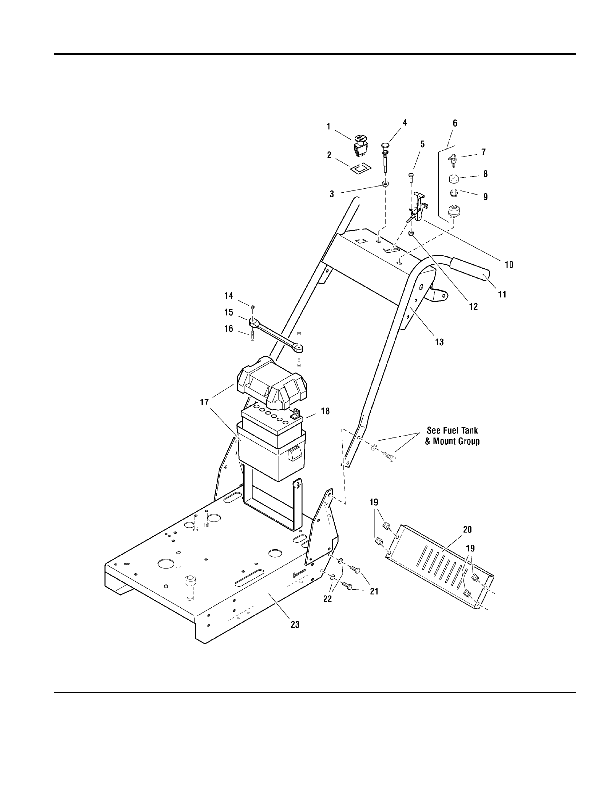
Engine Frame & Handle Bars Group - Electric Start
PART NO. DESCRIPTIONREF NO. QTY.
1 22180 1 SWITCH, PTO
2 22222 1 SWITCH RETAINER RING
3 25035 1 NUT, 3/8-24 Hex
4 46501 1 CABLE, Choke Control, 47"
5 25010-6 2 BOLT, 1/4-20 x 3/4
6 20927 1 SWITCH, Ignition, Complete (Includes Ref No. 7 - 9)
7 22789 1 KEY, Ignition, Molded Set
8 22790 1 COVER
9 22791 1 PLASTIC NUT
10 47629 1 CABLE, Throttle Control, 46"
11 21841 2 GRIP, Foam
12 25095 2 NUT, 1/4-20 Hex Nylon Lock
13 61279 1 HANDLE BAR ASSEMBLY
14 25271 2 NUT, #10-24 Hex Nylon Lock
15 21670 1 RUBBER STRAP
16 25270 2 SCREW, #10-24 x 1
17 46188 1 BATTERY BOX
18 - 1 BATTERY, Lawn & Garden, 12V (BCIU1, 340 CCA)
19 22308 4 BODY CLIP, 5/16-18
20 47735 1 REAR SHIELD
21 25011-6 4 BOLT, 5/16-18 x 3/4
22 25155 4 WASHER, 5/16" SAE
23 49229 1 ENGINE DECK ASSEMBLY
Footnotes
The above parts group applies to the following Mfg. Nos.:
5900604
HC36KAV13E
© Copyright Ferris Industries. All Rights Reserved.
2005
5
TP 400-7077-08-HC-F
Page 6
Engine Frame & Handle Bars Group - Manual Start
NOTE: Unless noted otherwise,
use the standard hardware torque
specification chart.
077HBRM0
The above parts group applies to the following Mfg. Nos.:
HC32KAV13
© Copyright Ferris Industries. All Rights Reserved.
2005
6
TP 400-7077-08-HC-F
Page 7

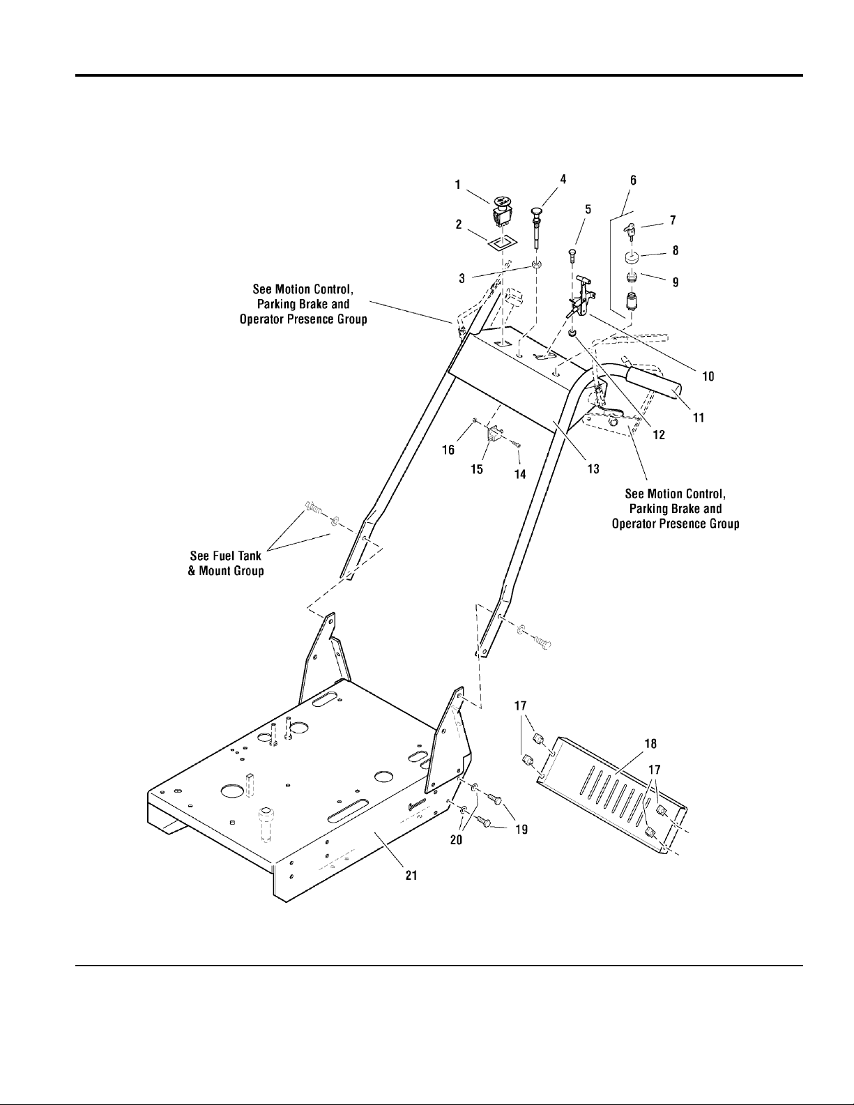
Engine Frame & Handle Bars Group - Manual Start
PART NO. DESCRIPTIONREF NO. QTY.
1 22180 1 SWITCH, PTO
2 22222 1 SWITCH RETAINER RING
3 25035 1 NUT, 3/8-24 Hex
4 46501 1 CABLE, Choke Control, 47"
5 25010-6 2 BOLT, 1/4-20 x 3/4
6 21842 1 SWITCH, Ignition, Complete (Includes Ref No. 7 - 9)
7 22789 1 KEY, Ignition, Molded Set
8 22790 1 COVER
9 22791 1 PLASTIC NUT
10 47629 1 CABLE, Throttle Control, 46"
11 21841 2 GRIP, Foam
12 25095 2 NUT, 1/4-20 Hex Nylon Lock
13 47905 1 HANDLE BAR ASSEMBLY
14 25179-4 2 SCREW, #10-24 x 1/2
15 21769 1 SWITCH, Plunger, NC
16 25029 2 NUT, #10-24 Hex
17 22308 4 BODY CLIP, 5/16-18
18 47735 1 REAR SHIELD
19 25011-6 4 BOLT, 5/16-18 x 3/4
20 25155 4 WASHER, 5/16" SAE
21 48230 1 ENGINE DECK ASSEMBLY
Footnotes
The above parts group applies to the following Mfg. Nos.:
HC32KAV13
© Copyright Ferris Industries. All Rights Reserved.
2005
7
TP 400-7077-08-HC-F
Page 8

Fuel Supply Hose & Tank Replacement Parts Group - Electric Start
NOTE: Unless noted otherwise,
use the standard hardware torque
specification chart.
077fshe0
The above parts group applies to the following Mfg. Nos.:
5900604
HC36KAV13E
© Copyright Ferris Industries. All Rights Reserved.
2005
8
TP 400-7077-08-HC-F
Page 9

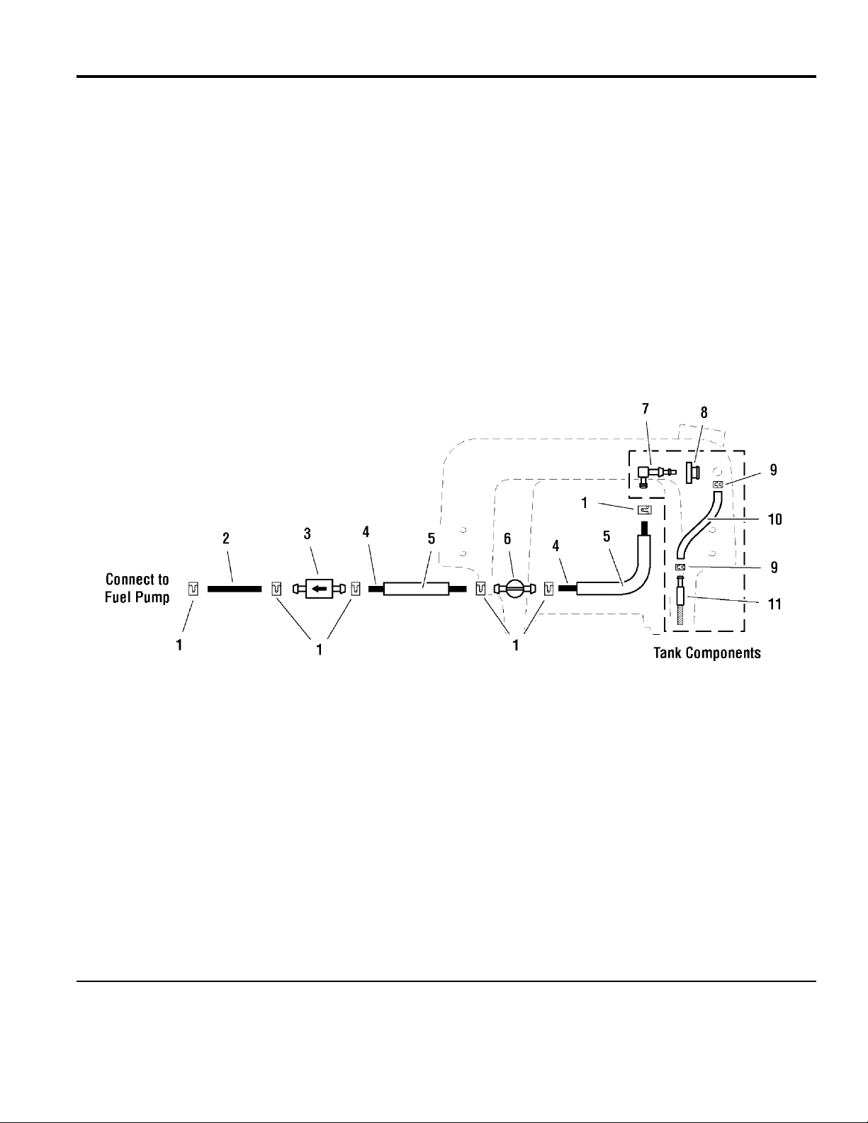
Fuel Supply Hose & Tank Replacement Parts Group - Electric Start
PART NO. DESCRIPTIONREF NO. QTY.
1 20835 6 CLAMP, Hose
2 50831-7 1 1/4" Fuel Line, 7" Long (supplied with engine)
3 21178-3 1 FUEL FILTER
4 50831-35 1 1/4" Fuel Line, 35" Long
5 50833-22 1 WIRE LOOM, 22"
6 21235 1 VALVE, Fuel Shut-Off
7 50831-4 1 1/4" Fuel Line, 4" Long
8 23061 1 ELBOW FITTING
9 1726400 1 GROMMET
10 23069 2 HOSE CLAMP
11 50925-20 1 HOSE, 20"
12 23067 1 SCREEN FITTING
Footnotes
The above parts group applies to the following Mfg. Nos.:
5900604
HC36KAV13E
© Copyright Ferris Industries. All Rights Reserved.
2005
9
TP 400-7077-08-HC-F
Page 10
Fuel Supply Hose & Tank Replacement Parts Group - Manual Start
NOTE: Unless noted otherwise,
use the standard hardware torque
specification chart.
077FSHM0
The above parts group applies to the following Mfg. Nos.:
HC32KAV13
© Copyright Ferris Industries. All Rights Reserved.
2005
10
TP 400-7077-08-HC-F
Page 11

Fuel Supply Hose & Tank Replacement Parts Group - Manual Start
PART NO. DESCRIPTIONREF NO. QTY.
1 20835 6 CLAMP, Hose
2 50831-7 1 1/4" Fuel Line, 7" Long (supplied with engine)
3 21178-3 1 FUEL FILTER
4 50831-19.5 2 1/4" Fuel Line, 19-1/2" Long
5 50833-18 2 WIRE LOOM, 18"
6 21235 1 VALVE, Fuel Shut-Off
7 23061 1 ELBOW FITTING
8 1726400 1 GROMMET
9 23069 2 HOSE CLAMP
10 50925-20 1 HOSE, 20"
11 23067 1 SCREEN FITTING
Footnotes
The above parts group applies to the following Mfg. Nos.:
HC32KAV13
© Copyright Ferris Industries. All Rights Reserved.
2005
11
TP 400-7077-08-HC-F
Page 12
Fuel Tank & Mount Group
NOTE: Unless noted otherwise,
use the standard hardware torque
specification chart.
077TNK0
The above parts group applies to the following Mfg. Nos.:
HC36KAV13E
5900604
HC32KAV13
© Copyright Ferris Industries. All Rights Reserved.
2005
12
TP 400-7077-08-HC-F
Page 13

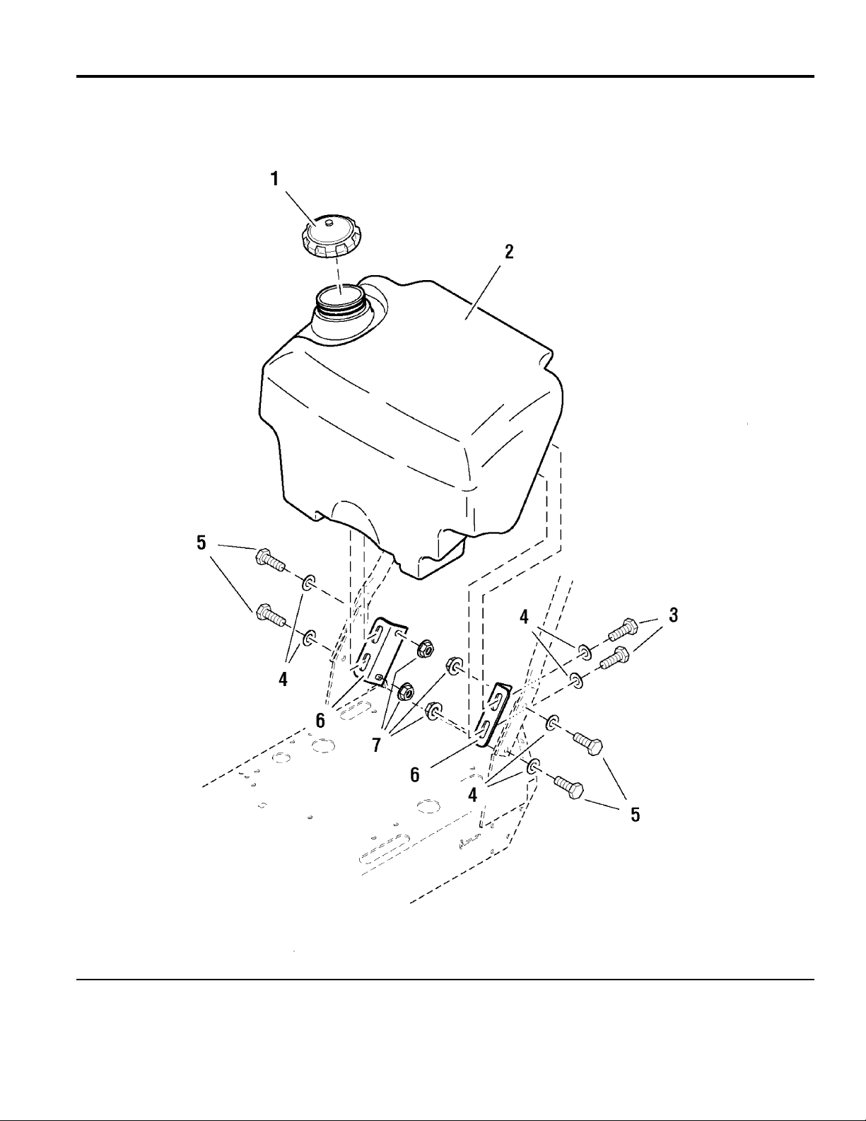
Fuel Tank & Mount Group
PART NO. DESCRIPTIONREF NO. QTY.
1 22158 1 FUEL TANK CAP
2 48149 1 FUEL TANK
3 25013-6 4 BOLT, 3/8-16 x 3/4
4 25156 8 WASHER, 3/8" SAE
5 25013-10 4 BOLT, 3/8-16 x 1-1/4
6 49228 2 FUEL TANK MOUNT
7 25128 4 NUT, 3/8-16 Hex Serrated Flange
Footnotes
The above parts group applies to the following Mfg. Nos.:
HC36KAV13E
5900604
HC32KAV13
© Copyright Ferris Industries. All Rights Reserved.
2005
13
TP 400-7077-08-HC-F
Page 14
Engine, PTO & Deck Drive Idler Group - Manual Start
NOTE: Unless noted otherwise,
use the standard hardware torque
specification chart.
077ENGW0
The above parts group applies to the following Mfg. Nos.:
HC32KAV13
© Copyright Ferris Industries. All Rights Reserved.
2005
14
TP 400-7077-08-HC-F
Page 15

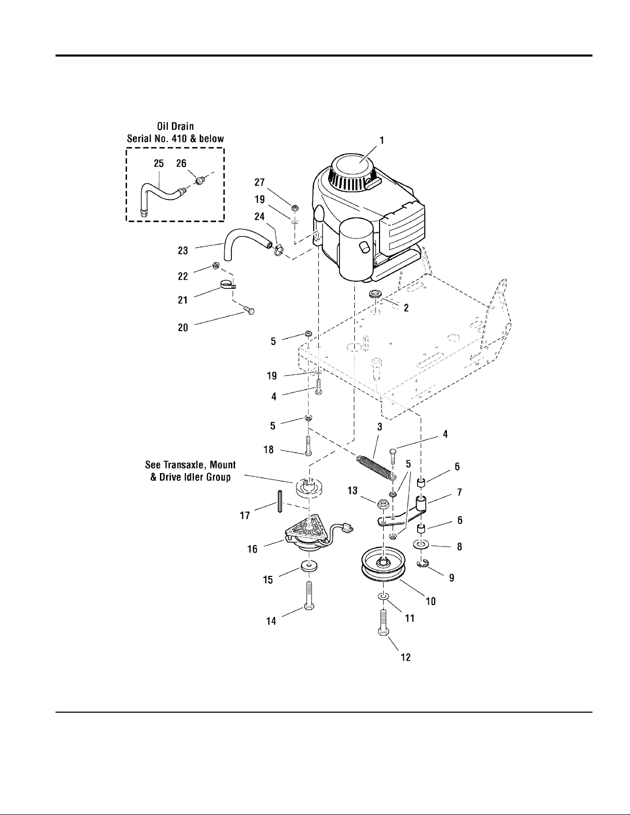
Engine, PTO & Deck Drive Idler Group - Manual Start
PART NO. DESCRIPTIONREF NO. QTY.
1 22907 1 ENGINE, 13HP Kawasaki (Model FH381V)
1 21178-3 1 FUEL FILTER
1 21334-1 1 OIL FILTER (49065-2078)
1 - 1 PRE-CLEANER (11013-7016)
1 - 1 AIR FILTER (11013-7017)
1 - 1 MUFFLER (49070-7002)
1 - 1 EXHAUST MANIFOLD (18088-7001)
1 - 1 MANIFOLD HEAT SHIELD (13271-7022)
1 - 2 EXHAUST MANIFOLD GASKET (11060-7021)
1 - 1 RECOIL ASSEMBLY, Complete (49088-7001)
2 21379 1 GROMMET, 7/8"
3 21103 1 SPRING, Extension
4 25011-12 5 BOLT, 5/16-18 x 1-1/2
5 25139 4 NUT, 5/16-18 Hex Large Serrated Flange
6 20876B 2 BUSHING, Brass
7 47661 1 DECK DRIVE IDLER ARM
8 25160 1 WASHER, 3/4" SAE
9 20863 1 C-CLIP
10 21369 1 IDLER PULLEY
11 25158 1 WASHER, 1/2" SAE
12 25018-20 1 BOLT, 1/2-20 x 2-1/2
13 25098 1 NUT, 1/2-20 Hex Nylon Lock
14 47632 1 CRANKSHAFT BOLT, 7/16 x 2-3/4
15 42132 1 SPACER, .45 x 1.62 x .37
16 1717664 1 ELECTRIC CLUTCH
17 50407-3 1 KEY, 1/4 SQ. X 2
18 25011-18 1 BOLT, 5/16-18 x 2-1/4
19 25155 5 WASHER, 5/16" SAE
20 25011-6 1 BOLT, 5/16-18 x 3/4
21 23173 1 CLAMP
22 25127 1 NUT, 5/16-18 Hex Small Serrated Flange
23 50857-10.5 1 HOSE, 10-1/2"
24 21392 1 CLAMP, #6 Hose
25 48681 1 OIL DRAIN HOSE (S/N: 101-410)
26 22234 1 ADAPTER, Oil Drain (S/N: 101-410)
27 25057 4 NUT, 5/16-18 Hex Nylon Lock
Footnotes
- See your local Kawasaki engine dealer for parts & service.
The above parts group applies to the following Mfg. Nos.:
HC32KAV13
© Copyright Ferris Industries. All Rights Reserved.
2005
15
TP 400-7077-08-HC-F
Page 16
Engine, PTO & Deck Drive Idler Group - Electric Start
NOTE: Unless noted otherwise,
use the standard hardware torque
specification chart.
077engw1
The above parts group applies to the following Mfg. Nos.:
HC36KAV13E
5900604
© Copyright Ferris Industries. All Rights Reserved.
2005
16
TP 400-7077-08-HC-F
Page 17

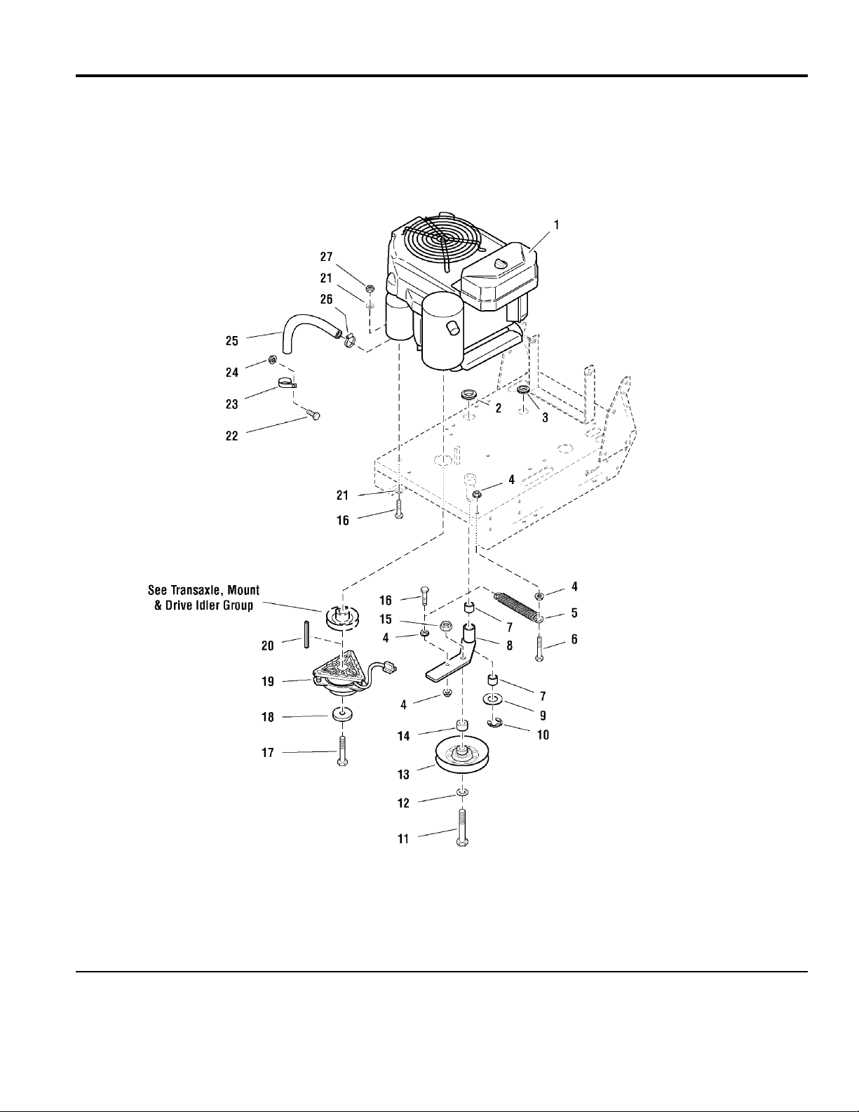
Engine, PTO & Deck Drive Idler Group - Electric Start
PART NO. DESCRIPTIONREF NO. QTY.
1 23399 1 ENGINE, 13HP Kawasaki (Model FH381V)
2 21379 1 GROMMET, 7/8"
3 21077 1 GROMMET, 1/2"
4 25139 4 NUT, 5/16-18 Hex Large Serrated Flange
5 23400 1 SPRING, Extension
6 25011-18 1 BOLT, 5/16-18 x 2-1/4
7 20876B 2 BUSHING, Brass
8 49208 1 DECK DRIVE IDLER ARM
9 25160 1 WASHER, 3/4" SAE
10 20863 1 C-CLIP
11 25017-22 1 BOLT, 1/2-13 x 2-3/4
12 25158 1 WASHER, 1/2" SAE
13 21097 1 PULLEY, V-Idler
14 49220 1 SPACER, .52 x 1.00 x .38
15 25056 1 NUT, 1/2-13 Hex Nylon Lock
16 25011-12 5 BOLT, 5/16-18 x 1-1/2
17 47632 1 CRANKSHAFT BOLT, 7/16 x 2-3/4
18 42132 1 SPACER, .45 x 1.62 x .37
19 1717664 1 ELECTRIC CLUTCH
20 50407-3 1 KEY, 1/4 SQ. X 2
21 25155 5 WASHER, 5/16" SAE
22 25011-6 1 BOLT, 5/16-18 x 3/4
23 23173 1 CLAMP
24 25127 1 NUT, 5/16-18 Hex Small Serrated Flange
25 50857-10.5 1 HOSE, 10-1/2"
26 21392 1 CLAMP, #6 Hose
27 25057 4 NUT, 5/16-18 Hex Nylon Lock
Footnotes
- See your local Kawasaki engine dealer for parts & service.
The above parts group applies to the following Mfg. Nos.:
HC36KAV13E
5900604
© Copyright Ferris Industries. All Rights Reserved.
2005
17
TP 400-7077-08-HC-F
Page 18

Motion Control, Parking Brake & Operator Presence Group - Electric Start
NOTE: Unless noted otherwise,
use the standard hardware torque
specification chart.
077mcge0
The above parts group applies to the following Mfg. Nos.:
HC36KAV13E
5900604
© Copyright Ferris Industries. All Rights Reserved.
2005
18
TP 400-7077-08-HC-F
Page 19

Motion Control, Parking Brake & Operator Presence Group - Electric Start
PART NO. DESCRIPTIONREF NO. QTY.
1 25510 1 FOAM GRIP
2 61278 1 BRAKE HANDLE SHAFT ASSEMBLY
3 22438 1 SWITCH, Plunger, NO/NO
4 25029 8 NUT, #10-24 Hex
5 21769 1 SWITCH, Plunger, NC
6 25179-4 8 SCREW, #10-24 x 1/2
7 21098 4 BEARING, Flange
8 61495 1 BRAKE ROD
9 20047 3 COLLAR, 5/16" Set
10 25057 8 NUT, 5/16-18 Hex Nylon Lock
11 25155 8 WASHER, 5/16" SAE
12 25011-6 8 BOLT, 5/16-18 x 3/4
13 25100 2 NUT, 3/8-16 Hex Side Lock
14 25010-8 6 BOLT, 1/4-20 x 1
15 61693 4 SLIDE SPACER
16 61691 1 CONTROL HANDLE, LH
16 61702 1 CONTROL HANDLE, RH (Not Shown)
17 61713 2 SWITCH ACTUATOR
18 25126 10 NUT, 1/4-20 Hex Serrated Flange
19 25010-6 4 BOLT, 1/4-20 x 3/4
20 61689 1 HANDLE MOUNT, LH
20 61692 1 HANDLE MOUNT, RH (Not Shown)
21 21769 2 SWITCH, Plunger, NC
22 25223 2 SHOULDER BOLT, 1/2 x 1
23 61683 1 PIVOT CONTROL, LH
23 61685 1 PIVOT CONTROL, RH (Not Shown)
24 25213-8 7 CLEVIS PIN, 5/16 x 1
25 25201-6 8 COTTER PIN, 3/32" x 3/4"
26 20979 8 CLEVIS, 5/16-24, Plastic
27 25033 8 NUT, 5/16-24 Hex
28 47642 2 THUMB CONTROL ROD
29 25128 2 NUT, 3/8-16 Hex Serrated Flange
30 25127 2 NUT, 5/16-18 Hex Small Serrated Flange
31 25055-14 1 BOLT, 5/16-18 x 1-3/4 TFL
32 47697 1 CONTROL SHAFT ASSEMBLY
33 47740 1 LINK STUD
34 25013-32 1 BOLT, 3/8-16 x 4
35 49352 1 SPRING, Extension
36 48328 1 BRAKE LINKAGE ROD
37 22481 2 COLLAR, Set, 1/4"
38 47732 1 DUMP VALVE ROD
Footnotes
The above parts group applies to the following Mfg. Nos.:
HC36KAV13E
5900604
© Copyright Ferris Industries. All Rights Reserved.
2005
19
TP 400-7077-08-HC-F
Page 20

Motion Control, Parking Brake & Operator Presence Group - Manual Start
NOTE: Unless noted otherwise,
use the standard hardware torque
specification chart.
077MCGM0
The above parts group applies to the following Mfg. Nos.:
HC32KAV13
© Copyright Ferris Industries. All Rights Reserved.
2005
20
TP 400-7077-08-HC-F
Page 21

Motion Control, Parking Brake & Operator Presence Group - Manual Start
PART NO. DESCRIPTIONREF NO. QTY.
1 49175 1 OPERATOR PRESENCE HANDLE - RH
2 21490 2 GRIP, Vinyl
3 25034 2 NUT, 3/8-16 Hex
4 43417 2 HEX ADJUSTER
5 45943 2 SHOULDER SPACER
6 47723 1 SWITCH ROD
7 48327 1 BRAKE ROD
8 20047 3 COLLAR, 5/16" Set
9 42614 2 THUMB CONTROL LEVER, Complete (Includes Ref No. 10 - S/N: 210 & below)
10 25510 2 FOAM GRIP
11 42542 1 PIVOT CONTROL - RH (S/N: 210 & below)
12 25213-8 7 CLEVIS PIN, 5/16 x 1
13 20979 8 CLEVIS, 5/16-24, Plastic
14 25201-6 8 COTTER PIN, 3/32" x 3/4"
15 25033 8 NUT, 5/16-24 Hex
16 47642 2 THUMB CONTROL ROD
17 25100 2 NUT, 3/8-16 Hex Side Lock
18 25139 2 NUT, 5/16-18 Hex Large Serrated Flange
19 42541 1 PIVOT CONTROL - LH (S/N: 210 & below)
20 49176 1 OPERATOR PRESENCE HANDLE - LH
21 25011-6 6 BOLT, 5/16-18 x 3/4
22 25223 2 SHOULDER BOLT, 1/2 x 1
23 25128 2 NUT, 3/8-16 Hex Serrated Flange
24 25155 4 WASHER, 5/16" SAE
25 25057 4 NUT, 5/16-18 Hex Nylon Lock
26 21098 2 BEARING, Flange
27 25013-32 1 BOLT, 3/8-16 x 4
28 49352 1 SPRING, Extension
29 48328 1 BRAKE LINKAGE ROD
30 47732 1 DUMP VALVE ROD
31 22481 2 COLLAR, Set, 1/4"
32 47740 1 LINK STUD
33 47697 1 CONTROL SHAFT ASSEMBLY
34 25010-6 4 BOLT, 1/4-20 x 3/4
35 25126 4 NUT, 1/4-20 Hex Serrated Flange
36 48547 2 THUMB CONTROL LEVER, Complete (Includes Ref No. 10 - S/N: 211 & above)
37 48544 1 PIVOT CONTROL - RH (S/N: 211 & above)
38 48545 1 PIVOT CONTROL - LH (S/N: 211 & above)
39 25127 2 NUT, 5/16-18 Hex Small Serrated Flange (S/N: 1039 & above)
40 25055-14 1 BOLT, 5/16-18 x 1-3/4 TFL (S/N: 1039 & above)
Footnotes
The above parts group applies to the following Mfg. Nos.:
HC32KAV13
© Copyright Ferris Industries. All Rights Reserved.
2005
21
TP 400-7077-08-HC-F
Page 22

Transaxle & Mount Group
NOTE: Unless noted otherwise,
use the standard hardware torque
specification chart.
077TRN0
The above parts group applies to the following Mfg. Nos.:
5900604
HC36KAV13E
HC32KAV13
© Copyright Ferris Industries. All Rights Reserved.
2005
22
TP 400-7077-08-HC-F
Page 23

Transaxle & Mount Group
PART NO. DESCRIPTIONREF NO. QTY.
1 25096 1 NUT, 3/8-16 Hex Nylon Lock
2 25057 7 NUT, 5/16-18 Hex Nylon Lock
3 25155 12 WASHER, 5/16" SAE
4 47582 1 TRANSAXLE BRACE
5 25059-6 2 BOLT, Self-Tapping, 5/16-18 x 3/4
6 25011-6 3 BOLT, 5/16-18 x 3/4
7 48312 1 SKID PLATE
8 22967 1 HYDRO RETURN SPRING
9 25011-24 4 BOLT, 5/16-18 x 3
10 22905 1 HYDROSTATIC TRANSAXLE
11 23058 1 BELT
12 20807 1 SPRING, Extension
13 25100 2 NUT, 3/8-16 Hex Side Lock
14 25013-24 1 BOLT, 3/8-16 x 3
15 25165 2 WASHER, 3/8" Fender
16 47716 1 SPACER, .41 x .75 x 2.06
17 20876B 2 BUSHING, Brass
18 47717 1 TRANSAXLE IDLER ARM
19 43627 1 IDLER PULLEY
20 25156 1 WASHER, 3/8" SAE
21 25013-16 1 BOLT, 3/8-16 x 2
22 47914 1 TRANSAXLE DRIVE PULLEY
Footnotes
The above parts group applies to the following Mfg. Nos.:
5900604
HC36KAV13E
HC32KAV13
© Copyright Ferris Industries. All Rights Reserved.
2005
23
TP 400-7077-08-HC-F
Page 24

Transaxle - SERVICE PARTS
NOTE: Unless noted otherwise,
use the standard hardware torque
specification chart.
077TSP0
The above parts group applies to the following Mfg. Nos.:
HC36KAV13E
5900604
HC32KAV13
© Copyright Ferris Industries. All Rights Reserved.
2005
24
TP 400-7077-08-HC-F
Page 25

Transaxle - SERVICE PARTS
PART NO. DESCRIPTIONREF NO. QTY.
6 22905-1 10.5 SEALANT
9 22905-2 1 SHAFT, INPUT
10 22905-3 1 RING - RETAINING
11 22905-4 1 SPACER
12 22905-5 3 RING - RETAINING
13 22905-16 1 SEAL, Lip, .67 x 1.58 x .276
14 22905-6 1 BALL BEARING
32 22905-7 2 OUTBOARD SLEEVE BEARING
34 22905-17 2 LIP SEAL, Axle Seal
35 22905-8 1 AXLE SHAFT - RH
36 22905-9 1 AXLE SHAFT - LH
55 22905-10 1 SPRING - HELICAL COMPRESSION
56 22905-11 1 WASHER
57 22905-12 78.8 20W-50 OIL
101 22967 1 HYDRO RETURN SPRING
119 22905-13 1 FAN, 6", 10 BLADE
128 22905-14 1 EXPANSION TANK KIT
130 22905-15 1 FAN/PULLEY KIT (Includes Ref. No. 119)
Footnotes
The above parts group applies to the following Mfg. Nos.:
HC36KAV13E
5900604
HC32KAV13
© Copyright Ferris Industries. All Rights Reserved.
2005
25
TP 400-7077-08-HC-F
Page 26

Tire & Wheel Group
NOTE: Unless noted otherwise,
use the standard hardware torque
specification chart.
077WHL0
The above parts group applies to the following Mfg. Nos.:
HC32KAV13
HC36KAV13E
5900604
© Copyright Ferris Industries. All Rights Reserved.
2005
26
TP 400-7077-08-HC-F
Page 27

Tire & Wheel Group
PART NO. DESCRIPTIONREF NO. QTY.
1 48409 2 KEY, 3/16 SQ. X 2-1/2
2 20792S 2 DRIVE HUB
3 23104 2 WHEEL & TIRE ASSEMBLY, 16 x 6.5 x 8, Complete (Includes Ref No. 4 & 5)
4 23104-2 2 TIRE, 16. x 6.5 x 8
5 23104-1 2 WHEEL ASSEMBLY, 8 x 5.38
6 25520-3 8 SHIM
7 20863 2 C-CLIP
8 20601 8 LUG NUT, 1/2-20
Footnotes
The above parts group applies to the following Mfg. Nos.:
HC32KAV13
HC36KAV13E
5900604
© Copyright Ferris Industries. All Rights Reserved.
2005
27
TP 400-7077-08-HC-F
Page 28

Decals - Brand & Model
NOTE: Unless noted otherwise,
use the standard hardware torque
specification chart.
077dclb0
The above parts group applies to the following Mfg. Nos.:
HC32KAV13
HC36KAV13E
5900604
© Copyright Ferris Industries. All Rights Reserved.
2005
28
TP 400-7077-08-HC-F
Page 29

Decals - Brand & Model
PART NO. DESCRIPTIONREF NO. QTY.
1 22560 1 DECAL, Ferris Text Logo
2 48228 1 DECAL, ICC
3 48229 1 DECAL, HydroCut 32
4 49065 1 DECAL, HydroCut 36
Footnotes
The above parts group applies to the following Mfg. Nos.:
HC32KAV13
HC36KAV13E
5900604
© Copyright Ferris Industries. All Rights Reserved.
2005
29
TP 400-7077-08-HC-F
Page 30

Decals - Safety & Instruction
NOTE: Unless noted otherwise,
use the standard hardware torque
specification chart.
077dcls0
The above parts group applies to the following Mfg. Nos.:
HC32KAV13
HC36KAV13E
5900604
© Copyright Ferris Industries. All Rights Reserved.
2005
30
TP 400-7077-08-HC-F
Page 31

Decals - Safety & Instruction
PART NO. DESCRIPTIONREF NO. QTY.
1 48321 1 DECAL, Control Panel (Manual Start)
2 61465 1 DECAL, Control Panel (Electric Start)
3 49318 1 DECAL, Height Of Cut (32" model)
4 49021 1 DECAL, Height Of Cut (36" model)
5 47778 1 DECAL, Cut Height Adjust
6 61537 1 DECAL, Belt R&R (36" model)
7 1704473 1 DECAL, Hot Surface
8 49658 1 DECAL, Danger
9 21818 1 DECAL, Warning, Machine Will Climb
10 1704277 1 DECAL, Danger (Chute In Place)
11 1704276 2 DECAL, Danger (Hand Under Deck)
Footnotes
The above parts group applies to the following Mfg. Nos.:
HC32KAV13
HC36KAV13E
5900604
© Copyright Ferris Industries. All Rights Reserved.
2005
31
TP 400-7077-08-HC-F
Page 32

32" Mower Deck - Frame, Caster & Shield
NOTE: Unless noted otherwise,
use the standard hardware torque
specification chart.
0772FR0
The above parts group applies to the following Mfg. Nos.:
HC32KAV13
5900604
© Copyright Ferris Industries. All Rights Reserved.
2005
32
TP 400-7077-08-HC-F
Page 33

32" Mower Deck - Frame, Caster & Shield
PART NO. DESCRIPTIONREF NO. QTY.
1 48145 1 SHIELD INSERT
2 25299-4 4 SCREW, Allen Head, 1/4-20 x 1/2
3 48150 1 GUARD, MOWER HOUSING
4 48353 2 SHIELD MOUNT BRACKET
5 22308 4 BODY CLIP, 5/16-18
6 25169 4 WASHER, 1/4" Lock
7 25010-6 4 BOLT, 1/4-20 x 3/4
8 25013-8 8 BOLT, 3/8-16 x 1
9 25128 8 NUT, 3/8-16 Hex Serrated Flange
10 25013-20 4 BOLT, 3/8-16 x 2-1/2
11 25156 4 WASHER, 3/8" SAE
12 22319 4 KNOB
13 47648 1 FRAME RAIL - LH
14 22098 2 CAP, Plastic
15 48194 1 CROSS TUBE
16 48969 1 CASTER MOUNT FRAME, Complete (Includes Ref No. 17 & 28)
17 20095 2 GREASE FITTING
18 25017-44 2 BOLT, 1/2-13 x 5-1/2
19 41657 2 AXLE, Caster Wheel
20 21181S 2 WHEEL & TIRE ASSEMBLY, Silver, 9 x 3.5 x 4, Complete (Includes Ref No. 21 - 25)
21 21181-1 2 TIRE, Front, 9 x 3.5 x 4
22 21181-2 2 TUBE
23 21181S-3 2 HUB & BEARING ASSEMBLY, Complete, Silver (Includes Ref No. 24 & 25)
24 21182 2 BEARING, Roller (1 per tire)
25 21043 4 RETAINER, Bearing (2 per tire)
26 25056 2 NUT, 1/2-13 Hex Nylon Lock
27 48172 2 CASTER YOKE (Use with Ref No. 16, part no. 48969)
28 20823 4 BUSHING, Flange
29 25096 4 NUT, 3/8-16 Hex Nylon Lock
30 10114 2 COLLAR, 3/4" Split
31 47649 1 FRAME RAIL - RH
32 48968 1 CASTER MOUNT FRAME W/ LOCKS, Complete (Includes Ref No. 17 & 28)
33 48965 2 CASTER YOKE (Use with Ref No. 32, part no. 48968)
34 23274 2 VINYL CAP
Footnotes
The above parts group applies to the following Mfg. Nos.:
HC32KAV13
5900604
© Copyright Ferris Industries. All Rights Reserved.
2005
33
TP 400-7077-08-HC-F
Page 34

32" Mower Deck - Height Adjustment
NOTE: Unless noted otherwise,
use the standard hardware torque
specification chart.
0772HA0
The above parts group applies to the following Mfg. Nos.:
HC32KAV13
5900604
© Copyright Ferris Industries. All Rights Reserved.
2005
34
TP 400-7077-08-HC-F
Page 35

32" Mower Deck - Height Adjustment
PART NO. DESCRIPTIONREF NO. QTY.
1 25162 4 WASHER, 1" SAE
2 47682 1 DECK LIFT PIVOT - REAR
3 25356 8 SHOULDER BOLT, 1/2 x 3/8
4 47655 1 HEIGHT ADJUST ROD
5 48526 1 LINKAGE ADJUSTER
6 25100 1 NUT, 3/8-16 Hex Side Lock
7 25201-6 1 COTTER PIN, 3/32" x 3/4"
8 25046 8 NUT, 3/8-16 Hex Top Lock
9 10546 1 COLLAR, 3/8" Set
10 25156 6 WASHER, 3/8" SAE
11 22645 1 SPRING, Compression
12 47710 4 DECK ADJUST LINK
13 25011-8 4 BOLT, 5/16-18 x 1
14 25139 4 NUT, 5/16-18 Hex Large Serrated Flange
15 25013-10 2 BOLT, 3/8-16 x 1-1/4
16 44933 2 SPACER, .39 x .75 x .38
17 48549 2 COLLAR, Double Split, 1"
18 25128 7 NUT, 3/8-16 Hex Serrated Flange
19 47737 1 CUT HEIGHT INDICATOR
20 25034 1 NUT, 3/8-16 Hex
21 47681 1 DECK LIFT PIVOT - FRONT
22 25013-6 4 BOLT, 3/8-16 x 3/4
23 48439 2 HANGER PLATE
24 20095 1 GREASE FITTING
25 48548 1 WASHER, Nylon, 3/8
Footnotes
The above parts group applies to the following Mfg. Nos.:
HC32KAV13
5900604
© Copyright Ferris Industries. All Rights Reserved.
2005
35
TP 400-7077-08-HC-F
Page 36

32" Mower Deck - Housing, Spindles, Blades & Pulleys
NOTE: Unless noted otherwise,
use the standard hardware torque
specification chart.
0772HC0
The above parts group applies to the following Mfg. Nos.:
HC32KAV13
5900604
© Copyright Ferris Industries. All Rights Reserved.
2005
36
TP 400-7077-08-HC-F
Page 37

32" Mower Deck - Housing, Spindles, Blades & Pulleys
PART NO. DESCRIPTIONREF NO. QTY.
1 22918 1 BELT
2 50407-1 2 KEY, 1/4 SQ. X 1
3 47638 2 SPINDLE PULLEY
4 47725 8 SPACER
5 25013-8 1 BOLT, 3/8-16 x 1
6 47777 1 BELT GUIDE
7 25126 1 NUT, 1/4-20 Hex Serrated Flange
8 25392 10 NUT, 5/16-18 Hex Nylock Flange
9 61096 2 SPINDLE ASSEMBLY, Complete (Includes Ref No. 10 - 18)
10 23329 2 GREASE FITTING
11 25405 2 NUT, 3/4-16 Hex
12 25406 2 WASHER, 3/4" Belleville
13 49793 4 TRASH SHIELD
14 23330 4 BEARING
15 23296 2 RELIEF VALVE
16 61097 2 SPINDLE HOUSING
17 61099 2 SPACER, 1.00 x 1.25 x 1.75
18 61100 2 SPINDLE SHAFT
19 23156 8 BOLT, Flange Head, 5/16-18 x 1-1/4
20 20843 2 MOWER BLADE, 16-1/4"
21 25159 2 WASHER, 5/8" USS
22 25320-14 2 BOLT, 5/8-11 x 1-3/4
23 6647576 1 32" MOWER HOUSING ASSEMBLY (Includes safety decals)
24 25011-8 2 BOLT, 5/16-18 x 1
25 47724 1 DISCHARGE CHUTE
Footnotes
The above parts group applies to the following Mfg. Nos.:
HC32KAV13
5900604
© Copyright Ferris Industries. All Rights Reserved.
2005
37
TP 400-7077-08-HC-F
Page 38

36" Mower Deck - Frame, Caster & Shield
NOTE: Unless noted otherwise,
use the standard hardware torque
specification chart.
0773fr0
The above parts group applies to the following Mfg. Nos.:
HC36KAV13E
© Copyright Ferris Industries. All Rights Reserved.
2005
38
TP 400-7077-08-HC-F
Page 39

36" Mower Deck - Frame, Caster & Shield
PART NO. DESCRIPTIONREF NO. QTY.
1 48145 1 SHIELD INSERT
2 25299-4 4 SCREW, Allen Head, 1/4-20 x 1/2
3 48150 1 GUARD, Mower Deck
4 48353 2 SHIELD MOUNT BRACKET
5 22308 4 BODY CLIP, 5/16-18
6 25169 4 WASHER, 1/4" Lock
7 25010-6 4 BOLT, 1/4-20 x 3/4
8 25013-10 12 BOLT, 3/8-16 x 1-1/4
9 25128 8 NUT, 3/8-16 Hex Serrated Flange
10 25156 4 WASHER, 3/8" SAE
11 22319 4 KNOB
12 47648 1 FRAME RAIL - LH
13 49262 1 CASTER MOUNT FRAME, Complete (Includes Ref No. 14 & 32)
14 20095 2 GREASE FITTING
15 25095 4 NUT, 1/4-20 Hex Nylon Lock
16 49214 1 SHIELD MOUNT ANGLE
17 49217 1 RUBBER SHIELD
18 49216 1 SHIELD MOUNT BAR
19 25154 4 WASHER, 1/4" SAE
20 25010-10 4 BOLT, 1/4-20 X 1
21 49215 2 SHIELD MOUNT BRACKET
22 25017-44 2 BOLT, 1/2-13 x 5-1/2
23 41657 2 AXLE, Caster Wheel
24 21181S 2 WHEEL & TIRE ASSEMBLY, Silver, 9 x 3.5 x 4, Complete (Includes Ref No. 25 - 29)
25 21181-1 2 TIRE, Front, 9 x 3.5 x 4
26 21181-2 2 TUBE
27 21181S-3 2 HUB & BEARING ASSEMBLY, Complete, Silver (Includes Ref No. 28 & 29)
28 21182 2 BEARING, Roller (1 per tire)
29 21043 4 RETAINER, Bearing (2 per tire)
30 25056 2 NUT, 1/2-13 Hex Nylon Lock
31 48172 2 CASTER YOKE
32 20823 4 BUSHING, Flange
33 25096 4 NUT, 3/8-16 Hex Nylon Lock
34 10114 2 COLLAR, 3/4" Split
35 23274 2 VINYL CAP
36 47649 1 FRAME RAIL - RH
37 61717 1 WIRE GUARD
Footnotes
The above parts group applies to the following Mfg. Nos.:
HC36KAV13E
© Copyright Ferris Industries. All Rights Reserved.
2005
39
TP 400-7077-08-HC-F
Page 40

36" Mower Deck - Height Adjustment
NOTE: Unless noted otherwise,
use the standard hardware torque
specification chart.
0773ha0
The above parts group applies to the following Mfg. Nos.:
HC36KAV13E
© Copyright Ferris Industries. All Rights Reserved.
2005
40
TP 400-7077-08-HC-F
Page 41

36" Mower Deck - Height Adjustment
PART NO. DESCRIPTIONREF NO. QTY.
1 25162 4 WASHER, 1" SAE
2 47682 1 DECK LIFT PIVOT - REAR
3 25356 8 SHOULDER BOLT, 1/2 x 3/8
4 47655 1 HEIGHT ADJUST ROD
5 48526 1 LINKAGE ADJUSTER
6 25100 1 NUT, 3/8-16 Hex Side Lock
7 25201-6 1 COTTER PIN, 3/32" x 3/4"
8 25046 8 NUT, 3/8-16 Hex Top Lock
9 10546 1 COLLAR, 3/8" Set
10 25156 6 WASHER, 3/8" SAE
11 22645 1 SPRING, Compression
12 47710 4 DECK ADJUST LINK
13 25011-8 4 BOLT, 5/16-18 x 1
14 25139 4 NUT, 5/16-18 Hex Large Serrated Flange
15 25013-10 2 BOLT, 3/8-16 x 1-1/4
16 44933 2 SPACER, .39 x .75 x .38
17 48549 2 COLLAR, Double Split, 1"
18 25128 7 NUT, 3/8-16 Hex Serrated Flange
19 47737 1 CUT HEIGHT INDICATOR
20 25034 1 NUT, 3/8-16 Hex
21 47681 1 DECK LIFT PIVOT - FRONT
22 25013-8 4 BOLT, 3/8-16 x 1
23 48439 2 HANGER PLATE
24 20095 1 GREASE FITTING
25 48548 1 WASHER, Nylon, 3/8
Footnotes
The above parts group applies to the following Mfg. Nos.:
HC36KAV13E
© Copyright Ferris Industries. All Rights Reserved.
2005
41
TP 400-7077-08-HC-F
Page 42

36" Mower Deck - Housing, Spindles, Blades & Pulleys
NOTE: Unless noted otherwise,
use the standard hardware torque
specification chart.
0773hc0
The above parts group applies to the following Mfg. Nos.:
HC36KAV13E
© Copyright Ferris Industries. All Rights Reserved.
2005
42
TP 400-7077-08-HC-F
Page 43

36" Mower Deck - Housing, Spindles, Blades & Pulleys
PART NO. DESCRIPTIONREF NO. QTY.
1 23262 1 BELT
2 25324-32 2 CARRIAGE BOLT, 1/2-13 x 4
3 25158 2 WASHER, 1/2" SAE
4 25056 2 NUT, 1/2-13 Hex Nylon Lock
5 45023 2 SPACER, .52 x 1.00 x .44
6 23264 1 IDLER PULLEY
7 48994 1 IDLER MOUNT
8 25405 2 NUT, 3/4-16 Hex
9 25406 2 WASHER, 3/4" Belleville
10 49218 1 SPACER, 1.00 x 1.57 x .69
11 49238 1 BELT, Chevron
12 25389 2 KEY, 1/4 SQ. X 3/4
13 48977 2 SPROCKET, Chevron
14 25392 8 NUT, 5/16-18 Hex Nylock Flange
15 61175 2 SPINDLE ASSEMBLY, Complete (Includes Ref No. 16 - 22)
16 23329 2 GREASE FITTING
17 49793 4 TRASH SHIELD
18 23330 4 BEARING
19 23296 2 RELIEF VALVE
20 61097 2 SPINDLE HOUSING
21 61099 2 SPACER, 1.00 x 1.25 x 1.75
22 61137 2 SPINDLE SHAFT w/ SADDLE
23 23156 8 BOLT, Flange Head, 5/16-18 x 1-1/4
24 21227 2 MOWER BLADE, 18"
25 25159 2 WASHER, 5/8" USS
26 25320-14 2 BOLT, 5/8-11 x 1-3/4
27 61727 1 PULLEY RETAINER
28 25011-6 2 BOLT, 5/16-18 x 3/4
29 48954 1 BAFFLE
30 22788 1 SPRING, Compression
31 48735 1 MOWER DECK HOUSING
32 25144-6 1 CARRIAGE BOLT, 1/4-20 x 3/4
33 25144 1 CARRIAGE BOLT, 1/4-20 x 1-1/4
34 1960518 2 PUSH NUT, 1/4, Black
35 61511 1 CHUTE SUPPORT PLATE
36 25154 2 WASHER, 1/4" SAE
37 1704873 1 CLAMP
38 1723938 1 SPRING, Torsion
39 1705449 1 DEFLECTOR
40 1723323 1 SPRING END CAP
41 25391 2 NUT, 1/4-20 Hex Nylock Flange
Footnotes
The above parts group applies to the following Mfg. Nos.:
HC36KAV13E
© Copyright Ferris Industries. All Rights Reserved.
2005
43
TP 400-7077-08-HC-F
Page 44

36" Mower Deck - Housing, Spindles, Blades & Pulleys
NOTE: Unless noted otherwise,
use the standard hardware torque
specification chart.
0773hc0
The above parts group applies to the following Mfg. Nos.:
HC36KAV13E
© Copyright Ferris Industries. All Rights Reserved.
2005
44
TP 400-7077-08-HC-F
Page 45

36" Mower Deck - Housing, Spindles, Blades & Pulleys
PART NO. DESCRIPTIONREF NO. QTY.
42 61807 1 CHUTE SUPPORT ROD
43 44933 1 SPACER, .39 x .75 x .38
44 49221 1 SPACER, 1.00 x 1.57 x 1.19
45 47638 1 SPINDLE PULLEY
46 50407-1 1 KEY, 1/4 SQ. X 1
Footnotes
The above parts group applies to the following Mfg. Nos.:
HC36KAV13E
© Copyright Ferris Industries. All Rights Reserved.
2005
45
TP 400-7077-08-HC-F
Page 46

Electrical Group - Electric Start
NOTE: Unless noted otherwise,
use the standard hardware torque
specification chart.
077egwe0
The above parts group applies to the following Mfg. Nos.:
5900604
HC36KAV13E
© Copyright Ferris Industries. All Rights Reserved.
2005
46
TP 400-7077-08-HC-F
Page 47

Electrical Group - Electric Start
PART NO. DESCRIPTIONREF NO. QTY.
1 61675 2 SWITCH, NC
2 22180 1 SWITCH, PTO
3 20927 1 SWITCH, Ignition, Complete (Includes Ref No. 4 - 6)
4 22789 1 KEY, Ignition, Molded Set
5 22790 1 COVER
6 22791 1 PLASTIC NUT
7 61470 1 WIRE HARNESS
8 22438 1 SWITCH, Plunger, NO/NO
9 21769 1 SWITCH, Plunger, NC
10 21405 1 POSITIVE (+) BATTERY CABLE, 22"
11 25126 4 NUT, 1/4-20 Hex Serrated Flange
12 25010-6 4 BOLT, 1/4-20 x 3/4
13 21406 1 NEGATIVE (-) BATTERY CABLE, 22"
14 - 1 BATTERY, Lawn & Garden, 12V (BCIU1, 340 CCA)
15 23216 2 NUT, Hex Jam, 5/16-24
16 23217 2 WASHER, Light Lock, 5/16
17 1724815 1 SOLENOID
18 21542 1 POSITIVE (+) BATTERY CABLE, 30"
Footnotes
The above parts group applies to the following Mfg. Nos.:
5900604
HC36KAV13E
© Copyright Ferris Industries. All Rights Reserved.
2005
47
TP 400-7077-08-HC-F
Page 48

Electrical Group - Manual Start
NOTE: Unless noted otherwise,
use the standard hardware torque
specification chart.
077EGWM0
The above parts group applies to the following Mfg. Nos.:
HC32KAV13
© Copyright Ferris Industries. All Rights Reserved.
2005
48
TP 400-7077-08-HC-F
Page 49

Electrical Group - Manual Start
PART NO. DESCRIPTIONREF NO. QTY.
1 47772 1 WIRE HARNESS
2 22180 1 SWITCH, PTO
3 21842 1 SWITCH, Ignition, Complete (Includes Ref No. 4 - 6)
4 22789 1 KEY, Ignition, Molded Set
5 22790 1 COVER
6 22791 1 PLASTIC NUT
7 21769 1 SWITCH, Plunger, NC
Footnotes
The above parts group applies to the following Mfg. Nos.:
HC32KAV13
© Copyright Ferris Industries. All Rights Reserved.
2005
49
TP 400-7077-08-HC-F
Page 50

Electrical Schematic - Manual Start
077eswm0
The above parts group applies to the following Mfg. Nos.:
HC32KAV13
© Copyright Ferris Industries. All Rights Reserved.
2005
50
TP 400-7077-08-HC-F
Page 51

Electrical Schematic - Electric Start
077eswe0
The above parts group applies to the following Mfg. Nos.:
HC36KAV13E
5900604
© Copyright Ferris Industries. All Rights Reserved.
2005
51
TP 400-7077-08-HC-F
Page 52

Page 53

Hardware Identification & Torque Specifications
Common Hardware Types
Hex Head Capscrew
Carriage Bolt
Standard Hardware Sizing
When a washer or nut is identified as 1/2”, this is the
Nominal size
second number is present it represent the
When bolt or capscrew is identified as 1/2 - 16 x 2”, this
means the
second number represents the
example, and the final number is the
bolt or screw (in this example 2 inches long).
, meaning the
Nominal size
inside diameter
, or
body diameter
threads per inch
body length
Washer
Lockwasher
Hex Nut
is 1/2 inch; if a
threads per inch
is 1/2 inch; the
(16 in this
of the
The guides and ruler furnished below are designed to
help you select the appropriate hardware and tools.
0
1/4 3/4
1/2
Nut, 1/2”
Inside
Diameter
1
1/4 3/4
1/2
Screw, 1/2 x 2
2
1/4 3/4
1/2
3
1/4 3/4
1/2
4
Body
Diameter
Body
Length
Torque Specification Chart
FOR STANDARD MACHINE HARDWARE (Tolerance ± 20%)
Hardware
Grade
Size Of
Hardware ft/lbs Nm. ft/lbs Nm. ft/lbs Nm.
8-32
8-36
10-24
10-32
1/4-20
1/4-28
5/16-18 11 15.0 17 23.1 25 34.0
5/16-24 12 16.3 19 25.8 27 34.0
3/8-16 20 27.2 30 40.8 45 61.2
3/8-24 23 31.3 35 47.6 50 68.0
7/16-14 30 40.8 50 68.0 70 95.2
7/16-20 35 47.6 55 74.8 80 108.8
1/2-13 50 68.0 75 102.0 110 149.6
1/2-20 55 74.8 90 122.4 120 163.2
9/16-12 65 88.4 110 149.6 150 204.0
9/16-18 75 102.0 120 163.2 170 231.2
5/8-11 90 122.4 150 204.0 220 299.2
5/8-18 100 136 180 244.8 240 326.4
3/4-10 160 217.6 260 353.6 386 525.0
3/4-16 180 244.8 300 408.0
7/8-9 140 190.4 400 544.0 600 816.0
7/8-14 155 210.8 440 598.4 660 897.6
1-8 220 299.2 580 788.8 900 1,244.0
1-12 240 326.4 640 870.4 1,000 1,360.0
1. These torque values are to be used for all hardware
excluding: locknuts, self-tapping screws, thread forming
screws, sheet metal screws and socket head setscrews.
2. Recommended seating torque values for locknuts:
a. for prevailing torque locknuts - use 65% of grade 5
torques.
b. for flange whizlock nuts and screws - use 135% of
grade 5 torques.
3. Unless otherwise noted on assembly drawings, all torque
values must meet this specification.
No
Marks
SAE Grade 2 SAE Grade 5 SAE Grade 8
in/lbs in/lbs
19
20
27
31
66
76
2.1
2.3
3.1
3.5
7.6 8 10.9 12 16.3
8.6 10 13.6 14 19.0
30
31
43
49
NOTES
3.4
3.5
4.9
5.5
in/lbs
41
43
60
68
420 571.2
4.6
4.9
6.8
7.7
Wrench & Fastener Size Guide
1/4
1/4” Bolt or Nut
Wrench—7/16”
5/16
5/16” Bolt or Nut
Wrench—1/2”
3/8
3/8” Bolt or Nut
Wrench—9/16”
7/16
DIA.
7/16” Bolt or Nut
Wrench (Bolt)—5/8”
Wrench (Nut)—11/16”
1/2
DIA.
1/2” Bolt or Nut
Wrench—3/4”
Page 54

Parts
Manual
HydroCut Series
Walk-Behind Mower
IT IS THE POLICY OF FERRIS INDUSTRIES TO IMPOVE ITS PRODUCTS WHENEVER IT IS
POSSIBLE AND PRACTICAL TO DO SO. WE RESERVE THE RIGHT TO MAKE CHANGES
OR ADD IMPROVEMENTS AT ANY TIME WITHOUT INCURRING ANY OBLIGATION TO
MAKE SUCH CHANGES ON PRODUCTS MANUFACTURED PREVIOUSLY.
Ferris Industries
5375 North Main Street
Munnsville, NY 13409 USA
800-933-6175
www.ferrisindustries.com
© Copyright Ferris Industries
All Rights Reserved. Printed In USA.
2005
 Loading...