

Page 1
Installation
Instructions
Derby Stallion Oil Cooler Kit
Par t No. 1846197
Kit Contents:
Ref Part No. Qty. Description
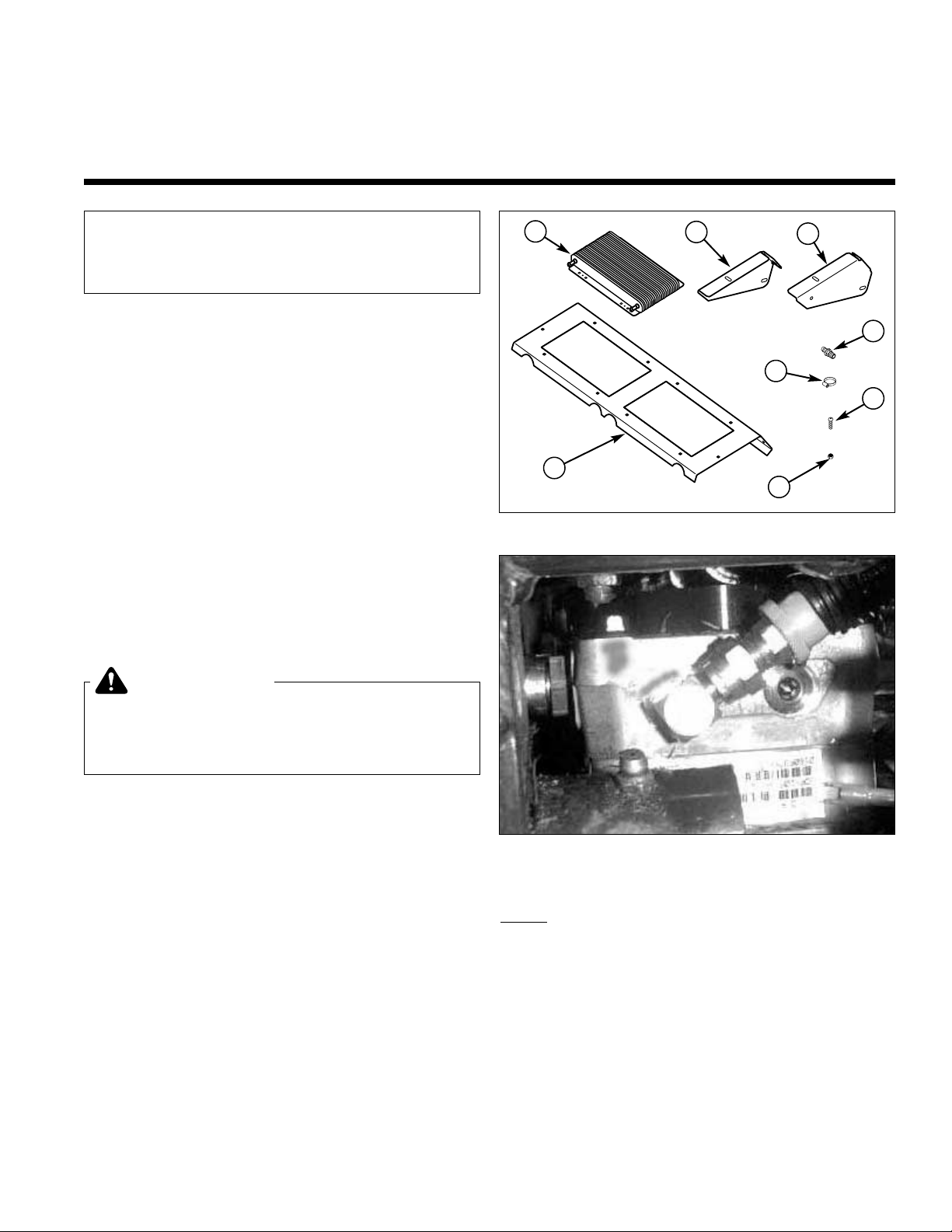
1 22467 2 Oil Cooler
2 1846152 1 Mount Bracket-Left
3 1846153 1 Mount Bracket-Right
4 1846154 1 Oil Cooler Mount
5 22106 2 3/8” Hose Fitting
6 21164 4 Hose Clamp
7 25299 8 Bolt, 1/4-20 x 3/4” Torx Head
8 25095 8 Nut, 1/4-20 Nylon Lock
9 50860-19 1 3/8” Hose, 19” (not shown)
10 50860-25 1 3/8” Hose, 25” (not shown)
11 50860-48 2 3/8” Hose, 48” (not shown)
12 50862-18 1 3/4” Wire Loom, 18” (not shown)
12 50862-24 1 3/4” Wire Loom, 24” (not shown)
13 21029 3 Long Tie Wrap (not shown)
14 21030 1 Short Tie Wrap (not shown)
This kit is for installing oil coolers to the
hydraulic system. This kit should be installed
when using the Triple Bagger Grass
Collection System.
WARNING
Before beginning any service work turn off the
PTO, set the parking brake,turn off the ignition,
and disconnect the spark plug wire(s).
1
© Copyright 2000 Ferris Industries. All Rights Reser ved.
REMOVAL & INSTALLATION
1. Park machine on a flat, level surface and engage the
parking brake.
2. Remove and discard the fuel tank tie bar and the left
and right mounting brackets. SAVE the mounting
hardware.
3. Remove the split collars from the control cross shaft
and carefully lift the shaft assembly from the saddles.
Set the shaft on the ledge of the rear seat support to
allow for increased access room.
4. Subassemble the 19” and 25” hose lengths with one
of the barbed fittings on each hose and the appropriate length of wire loom. Be sure the barbs are fully
inserted into the hose end. Applying a few drops of
oil on the barbs will make the assemble easier.
Figure 1. Kit Contents
NOTE: Some oil loss will occur when disconnecting the
hydraulic hoses. Remove and reconnect as quickly as
possible and prepare to contain the lost oil.
5. Remove the right return hose and loosen the jam nut
on the fitting on the pump. Rotate the fitting towards
the rear of the machine and point it slightly upwards
(see Figure 2). Tighten the jam nut.
6. Install the 19” hose assembly to the fitting on the
pump and tighten. Leave the free end of the hose
higher than the reservoir to prevent to hydraulic system from draining.
Figure 2. Fitting Orientation
1
4
3
2
8
7
6
5
For all Derby Stallion ZT2354 mowers
1846261
Rev. 9/2000
TP 200-7030-00-SL-D
Page 2
Installation Instructions 1846197
2
© Copyright 2000 Ferris Industries. All Rights Reser ved.
7. Block the front wheels and jack up the rear of the
machine and set on jack stands or wooden blocks.
Remove the left drive tire. This will allow for easier
access to the left hand pump.
8. Remove the left return hose and loosen the jam nut
on the fitting on the pump. Rotate the fitting towards
the rear of the machine and point it slightly upwards
(see Figure 2). Tighten the jam nut.
9. Install the 25” hose assembly to the fitting on the
pump and tighten. Leave the free end of the hose
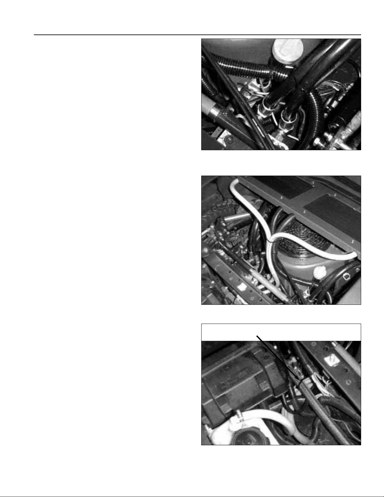
higher than the reservoir to prevent to hydraulic system from draining. Route the hose behind the highpressure hoses (see Figure 3).
10.Remove both return hoses from the top of the reservoir and save the hose clamps.
11.Reinstall the control cross shaft into the saddles.
Make sure the new hoses do not contact the shaft. If
the hose does contact the shaft, loosen the jam nut
on the fitting and rotate the fitting until approximately
1/4” clearance is obtained. Secure the cross shaft
with the split collars.
12.Route the 48” hoses under the control cross shaft
and through the clearance opening in the battery pan
near the right-hand pump, under the wiring harness
and under the 5/8” supply hose.
13.Connect the retur n hoses to the reser voir and secure
with the hose clamps previously removed.
14.Install the oil coolers in the oil cooler mount using the
torx bolts and nylon nuts supplied with this kit. Make
sure the hose barbs of the coolers are pointing
towards the half-holes in the mount.
15.Install the left and r ight side cooler mount brackets to
the fuel tanks using the bolts previously removed.
16.Install the oil cooler mount on the brackets, center
side-to-side and secure with the torx bolts and nylon
nuts previously removed.
17.Connect the hoses the the oil coolers. Connect the
hose from the right side barb of the oil reservoir to
the right side oil cooler and the hose from the left
side barb to the left side cooler. See Figure 4 for the
proper hose locations. Secure with the enclosed
hose clamps.
18.Install the tie wraps as shown in Figures 4-6. Use a
long tie wrap to secure the 48” hoses to the 5/8” supply hose. Position the hoses so the do not contact
the battery pan. Use the remaining two long tie
wraps the bundle the hoses together in front of the
engine. Be sure the tie wrap the hoses to the engine
screen. Use the shor t tie wrap to secure the 25”
hose to the engine oil dipstick tube. Do not overtighten the tie wraps or collapsing the hose may
result.
Figure 3. Left Return Hose Routing
Figure 4. Hose Routing
Tie Wrap
Figure 5. Tie Wrap Location
Page 3

Installation Instructions 1846197
3
© Copyright 2000 Ferris Industries. All Rights Reser ved.
19.Refill the oil reser voir to the “MAX OIL LEVEL HOT”
line. Use either Mobil 1, 15W-50 synthetic oil or
Castrol Syntec 5W-50 oil. DO
NOT use conventional
oils. Make sure area around the reservoir is free of
dust, dirt, or other debris.
20.Reinstall the left dr ive tire and remove the jack
stands. Lower the seat plate.
21.Make sure the parking brake is engaged, the control
handles locked in the “NEUTRAL” position and the
PTO switch is off. Reconnect the spark plug wires.
22.Start the engine and run it in the slowest throttle
position. Dismount the machine and raise the seat
plate.
23.Carefully watch the oil level in the reservoir while the
machine in running. The level will initially drop quickly as the oil coolers are being filled. Do not allow the
oil level to drop below 50% of the full capacity.
24.With the cap removed, look through the filler neck of
the oil reservoir and watch for oil flow at the return
line barbs. Once there is a continuously flow of oil,
the return side of the hydraulic system has been
filled. If necessar y, fill the oil reservoir to 1/2” below
the “MAX OIL LEVEL HOT” line.
25.Replace the oil reser voir cap and lower the seat
plate.
Figure 6. Tie Wrap Location
 Loading...