

Page 1

Supplemental Setup and Operating
Not for
Reproduction
Instructions and Illustrated Parts Lists
for Ferris Zero-Turn Riding Mowers Using
Propane Fuel
Model Description
5900690 IS3100ZBVP3261, Zero-Turn Riding Mower w/ Propane Fuel
5900691 IS3100ZBVP32, Zero-Turn Riding Mower w/ Propane Fuel
5900789 IS3100ZBVP3261, Zero-Turn Riding Mower w/ Propane Fuel & 16cc Pumps
5900790 IS3100ZBVP32, Zero-Turn Riding Mower w/ Propane Fuel & 16cc Pumps
5900942 IS3100ZBVP3261HT, Zero-Turn Riding Mower w/ Propane Fuel & 16cc Pumps
Briggs & Stratton Power Products Group, LLC.
5375 N. Main Street
Munnsville, NY 13409-4003
5404081
Rev U
Page 2

This manual is intended to supplement the operator’s manual included
Not for
Reproduction
with your machine. There is very important safety, operational and maintenance
information in this manual. Read and understand all information in your
operator’s manual and this supplement manual before attempting to operate this
machine. Save these original instructions for future reference.
Table of Contents
Operator Safety .................................................. 1
Propane Mower Operating Procedures ...................1
Propane Fuel Tank Filling Procedures ....................1
Procedures for Safe Handling of Propane ...............1
Features & Controls ........................................... 2
Control Functions ....................................................2
Operation ............................................................ 4
Checks Before Starting ...........................................4
Starting the Engine ..................................................4
Stopping the Rider ..................................................4
Regular Maintenance ......................................... 4
Removing the Propane Tanks .................................4
Re-installing the Propane Tanks .............................5
Initial Fill of a New Propane Tank ............................5
Excess Flow Valve ..................................................5
Leak Testing the Fuel System .................................6
Specifications ..................................................... 7
Seguridad del Operador .................................... 9
Funciones y Controles .................................... 10
Operación .......................................................... 12
Mantenimiento Regular ................................... 13
Especificaciones .............................................. 15
Illustrated Parts Lists....................................... 16
Tank Mount Group ................................................16
Instrument Control Panel Group ............................18
Fuel Supply Group ................................................20
Electrical Schematics
Charging Circuit ....................................................24
Cranking Circuit .....................................................25
Ignition Grounding Circuit / Operator
Presence ...............................................................26
PTO Clutch Circuit ................................................27
NOTE: In this manual, “left” and “right” are referred to as
seen from the operating position.
Briggs & Stratton Power Products Group, LLC.
Copyright © 2012 Briggs & Stratton Corporation
Milwaukee, WI, USA. All rights reserved.
FERRIS is a trademark of Briggs & Stratton Corporation
Milwaukee, WI, USA.
Contact Information:
Briggs & Stratton Power Products Group, LLC.
5375 N. Main St.
Munnsville, NY 13409-4003
(800) 933-6175
www.ferrisindustries.com
Spanish English
ES GB
Page 3

Operator Safety
Not for
Reproduction
WARNING
Avoid serious injury or death from operating
a mower using propane fuel. Follow mower
operating procedures, propane fuel and
propane fuel tank filling producedures.
Operator Safety
P/N: 5103596
Decal, Warning, Vapor Valve
MOWER OPERATING
PROCEDURES USING PROPANE
FUEL
Background
• Ferris propane mowers are designed to operate
on a propane vapor system, which draws vapor
from the fuel tank. It is not compatible with the
typical propane fork truck system that operate on
propane liquid drawn from the fuel tank.
• The fuel system is designed with a left hand
thread on the fuel hose and tank connections
intended to prevent use of a liquid propane tank
(using right hand threads). The mower will NOT
function correctly with a liquid propane fuel tank.
Operation
• Turn propane OFF at the fuel tank shut-off valve
at the end of each day, before changing fuel tanks
and/or transporting.
• Operate the mower on one propane tank at a
time. Keep the fuel tank shut-off valve on the
opposite side tank turned off.
• CLOSE the fuel tank shut-off valve on the propane
tank immediately if you smell raw propane. DO
NOT attempt to start engine until the problem has
been identified and repaired.
• Avoid fire hazard. Never open the tank vapor
(spud) valve while the tank is attached or near the
unit.
Service
• Do NOT bleed propane fuel indoors, in an
enclosed trailer, garage or other enclosed areas.
Propane is under pressure and highly flammable.
• Do NOT alter or adjust the propane fuel system in
any way.
• Store propane fuel tanks only in OUTSIDE
areas away from electric or gas appliances and
any possible source of spark, heat or heavy
equipment. The storage facility should be
constructed and located in compliance with local,
state, federal or provincial jursidictional safety
codes.
• Use ONLY a D.O.T. rated propane fuel tank. See
your Ferris dealer to obtain extra tanks.
• Regularly check the flexible supply line. Make
sure that they are in good condition. Replace
damaged or leaking components.
PROPANE FUEL TANK FILLING
PROCEDURES
• A propane fuel tank is a cylinder designed to
• Do not overfill the propane tank. Fill at an
• A new propane tank that has never been filled
FLAMMABLE
PROCEDURES FOR SAFE
HANDLING OF PROPANE
• If there is a propane (LP) gas leakage in the area,
• To protect yourself from the risk of frostbite from
contain a liquefied petroleum gas (propane)
under pressure that is highly flammable. Filling,
operating and servicing of this cylinder (tank)
must be conducted at an approved propane
dealer by persons properly trained and qualified in
accordance with local, state, federal and provincial
jurisdictional requirements.
approved propane dealer following the procedures
and specifications on the tank.
with propane requires special procedures to
properly purge the tank of air and fill for the first
time. Refer to the instructions on the propane
tank and fill only at an approved propane dealer
following the procedures and specifications on the
tank.
WARNING
Propane vapors are extremely flammable
GAS
2
and explosive.
Fire or explosion can cause severe burns
or death.
Frostbite can result from skin / eye contact
contact with leaking propane (LP) fluid.
do not attempt to start engine.
a potential propane (LP) fluid leak, always wear
protective clothing when working on the propane
system.
GB
1
Page 4

Features & Controls
Not for
Reproduction
Features & Controls
Instrument Control Panel
(S/N: 2014953656 & Below)
CONTROL FUNCTIONS
The information below briefly describes the function of individual controls. Starting, stopping, driving, and
mowing require the combined use of several controls applied in specific sequences. To learn what combination
and sequence of controls to use for various tasks see the OPERATION section.
Ground Speed Control Levers
These levers control the ground speed of the rider.
The left lever controls the left rear drive wheel and
the right controls the right rear drive wheel.
Moving a lever forward increases the FORWARD
speed of the associated wheel, and pulling back on a
lever increases the REVERSE speed.
Note: The further a lever is moved away from the
neutral position the faster the drive wheel will turn.
See the Operation section for steering instructions.
PTO (Power Take Off) Switch
The PTO switch engages and disengages the mower.
Pull UP on the switch to engage the mower, and push
DOWN to disengage the mower.
Throttle Control
Moving the throttle control fully forward is FULL
throttle position. Always operate the unit at FULL
throttle when mowing.
Seat Adjustment Lever
The seat can be adjusted forward and back. Move
the lever forward, position the seat as desired, and
release the lever to lock the seat in position.
Ignition Switch
The ignition switch starts and stops the engine, it has
three positions:
OFF Stops the engine and shuts off the
electrical system.
RUN Allows the engine to run and powers
the electrical system.
START Cranks the engine for starting.
NOTE: Never leave the ignition switch in the RUN
position with the engine stopped–this drains the
battery.
2
GB
www.ferrisindustries.com
Page 5

Features & Controls
Not for
Reproduction
Parking Brake
DISENGAGE Releases the parking
ENGAGE Locks the parking
Pull the parking brake lever back to engage the
parking brake. Move the lever fully forward to
disengage the parking brake. NOTE: To start the
unit the parking brake must be engaged.
Deck Lift Pedal, Cutting
Height Adjustment Pin & Deck Lift Lock
Lever
These control the cutting height of the mower deck.
Depress the pedal until it locks into the 5” (12,7cm)
position. Place the adjustment pin in the desired
cutting height and release the lift lock lever.
Hour Meter
The hour meter measures the number of hours the
PTO has been engaged. The hour meter has a self
contained power source so the total hours are always
visible.
Instrument Control Panel
(S/N: 2014953657 & Above)
brake.
brake.
FUEL TANK CONTROLS
Fuel Tank Shut-Off Valve
(One valve per tank)
The fuel shut off valves are located on the front of the
propane tanks. Turn the knob CLOCKWISE to close
the fuel shut off valve. Turn the knob COUNTERCLOCKWISE to open the fuel shut off valve.
When operating the unit, only one fuel tank shut-off
valve should be open at a time, so that LP gas is only
drawn from one tank at a time.
The propane tanks are equipped with a excess flow
valve that will automatically close and stop the flow of
propane from the tank if the flow of propane exceeds
the specified rate.
Fuel Level Guage
Displays the fuel level in the tank.
GB
3
Page 6

Operation
Not for
Reproduction
Operation
CHECKS BEFORE STARTING
• Check that crankcase is filled to the full mark on
the dipstick. See the engine Operator’s Manual for
instructions and oil recommendations.
• Make sure all nuts, bolts, screws and pins are in
place and tight.
• Adjust the seat position, and make certain you can
reach all controls from operator’s position.
• Make sure that the propane tanks are installed
correctly and secured tightly. Refer to engine
manual for fuel recommendations.
• Make sure that only one fuel shut-off valve is
OPEN. Do NOT run the machine with both fuel
shut-off valves opened at the same time.
WARNING
If you do not understand how a specific control
functions, or have not yet thoroughly read the
FEATURES & CONTROLS section, do so now.
Do NOT attempt to operate the tractor without
first becoming familiar with the location and
function of ALL controls.
6. After warming the engine, ALWAYS operate
the unit at FULL THROTTLE when mowing.
In the event of an emergency the engine can be
stopped by simply turning the ignition switch
to STOP. Use this method only in emergency
situations. For normal engine shut down follow the
procedure given in STOPPING THE RIDER.
STOPPING THE RIDER
1. Returning the ground speed control levers to the
middle position will stop tractor movement. Pivot
the levers outward and lock them in NEUTRAL.
2. Disengage the PTO by pushing down on the PTO
switch.
3. Engage the parking brake by pulling the handle up
until it locks into position.
4. Move the throttle control to 1/4 throttle position
and turn the ignition key to OFF. Remove the
key.
5. Close the fuel tank shut-off valve on the propane
tank by turning the fuel tank shut-off valve
CLOCKWISE.
STARTING THE ENGINE
1. Open the fuel shut off valve on one of the propane
tanks by turning the fuel shut off valve COUNTERCLOCKWISE. Leave the valve on the opposite
tank closed.
2. While sitting in the operator’s seat, engage the
parking brake and make sure the PTO switch is
disengaged and the ground speed control levers
are locked in the NEUTRAL position.
3. Set the engine throttle control to 1/4 throttle
position.
4. Insert the key into the ignition switch and turn it to
START.
NOTE: Allow the engine to crank for 3 seconds,
if the engine does not start, re-check to see if the
crankcase is filled to the full mark on the dipstick.
If necessary fill the crankcase to the full mark on
the dipstick. See the engine Operator’s Manual for
instructions and oil recommendations.
5. After the engine starts, allow the engine to warm
up for at least a minute before engaging the PTO
switch or driving the rider.
Warm up the engine by running it for at least a minute
before engaging the PTO switch or driving the rider.
Maintenance
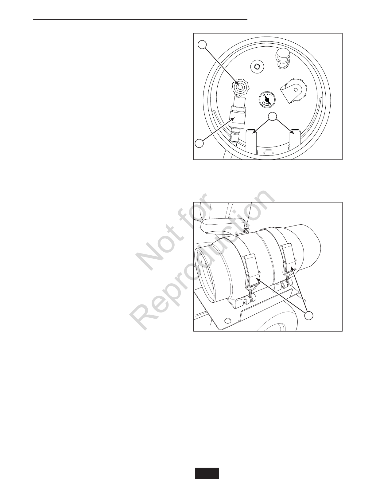
REMOVING THE PROPANE TANKS
The propane tanks must be removed from the
machine for re-filling and for long term storage.
1. Close the the fuel shut off valve (A, Figure 1) by
turning it CLOCKWISE.
2. The fuel supply hose fittings (B) are left-handed
threads. Rotate the fuel supply hose fitting to the
right to loosen the fuel supply hose fitting.
3. Release the propane tank straps (A, Figure 2) that
secure the propane tank to the machine.
4. Lift the propane tank straight up off the machine.
4
GB
www.ferrisindustries.com
Page 7
RE-INSTALLING THE PROPANE
Not for
Reproduction
TANKS
NOTE: The propane tank should be installed on
the unit so that the fuel shut-off valve and fuel level
gauge are pointing toward the rear of the machine by
the rear bumper.
1. Position the propane tank so that the tank
positioning bracket (C, Figure 1) fits into the slots
located on either side of the center slot.
2. Connect the fuel supply hose fitting (B) to the
tank. Turn the fuel supply hose fitting to the left to
tighten the fuel supply hose fitting.
3. Tighten the propane tank straps (A, Figure 2) that
secures the propane tank to the machine.
NOTE: The length of the propane tank straps are
adjustable. If the propane tank straps do not firmly
secure the propane tank in place, unclasp the
propane tanks straps, turn the handles clockwise and
then reclaps the propane tank brackets. Continue
this process until the propane tank straps hold the
tank firmly in place. DO NOT operate the machine
with a propane tank that is not firmly secured into
place.
NOTE: Wait until you are ready to start the machine
before re-opening the fuel shut off valve (A, Figure 1).
Regular Maintenance
A
C
B
Figure 1. Closing the Fuel Tank Shut-Off Valve
A. Fuel Shut Off Valve
B. Fuel Supply Hose Fitting (w/ Left Hand Threads)
C. Tank Positioning Bracket
INITIAL FILL OF A NEW PROPANE
TANK
A new propane tank that has never been filled with
propane requires special procedures to properly
purge the tank of air and fill for the first time. Refer
to the instructions on the propane tank and fill only at
an approved propane dealer following the procedures
and specifications on the tank.
EXCESS FLOW VALVE
The propane tanks on this unit are equipped with
excess flow valves which will close if the flow of
propane exceeds a specified rate.
Conditions that will cause the excess flow valves to
close are:
a) If a component of the propane system suffers
significant damage, allowing the mass escape of
propane.
b) If one propane tank is empty and the fuel shut-off
valve is not closed before opening the fuel shut-off
valve on the full tank. This causes the propane
to quickly flow from the full tank to the empty tank
until both tanks are at the same level.
A
Figure 2. Releasing the Tank Straps
A. Propane Tank Straps
GB
5
Page 8
Regular Maintenance
Not for
Reproduction
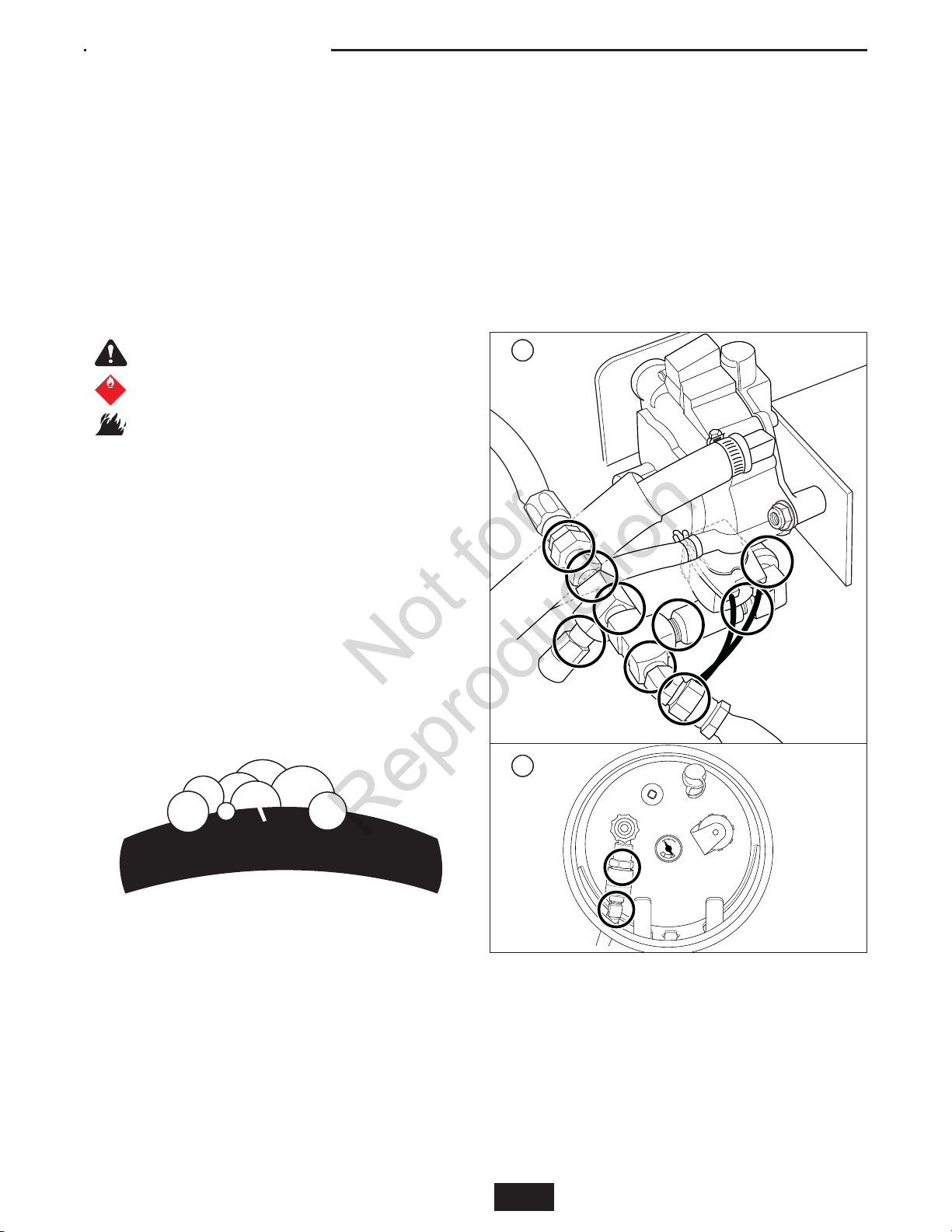
LEAK TESTING THE FUEL SYSTEM
This procedure should only be used when trying to
identify the location of a leak.
1. Create a mixture of 50% water and 50% liquid
dishwashing soap.
2. OPEN the fuel tank shut-off valve on the left
hand propane tanks (turn valve COUNTERCLOCKWISE. Leave the fuel tank shut-off valve
on the right tank closed propane tank closed.
3. Using a sponge, rag or small non-metallic brush,
apply the soap water mixture at each of the
locations circled in Figure 3.
WARNING
Gaseous vapors are extremely flammable
FLAMMABLE
GAS
2
and explosive.
Fire or explosion can cause severe burns
or death.
• DO NOT smoke or permit ignition sources in
the area while conducting a leak test.
• Perform leak test OUTDOORS only in a well
ventilated area.
• DO NOT perform a leak test with a match or
open flame.
• DO NOT perform a leak test while the unit is
in use.
• ALWAYS perform a leak test whenever any
fuel system components are changed.
9. When you are done testing the system make sure
that both fuel tank shut-off valves are CLOSED
until you are ready to use the unit again.
10. Wash off soapy residue with clean cold water and
towel dry.
11. Wait five minutes to allow all gas to evacuate the
area before starting the generator.
NOTE: The leak test must be performed in an area
that has adequate lighting in order to see if bubbles
are developing. DO NOT use a flashlight to check for
bubbles.
A
4. Check each location shown in Figure 3 for
growing bubbles, which indicate a fuel leak.
Bubbles will look something like this:
5. CLOSE the fuel tank shut-off valve (turn fully
CLOCKWISE).
6. Tighten or replace any leaking connections.
7. Repeate steps 2 through 6 until no leaks are
detected. DO NOT use the unit if leaks cannot be
stopped. Contact your authorized Ferris dealer for
assistance.
8. Repeat steps 2 through 8, with the fuel tank shutoff valve closed on the left propane tank and
the fuel tank shut-off valve opened on the right
propane tank.
B
Figure 3. Leak Test Locations
A. Regulator and Connections
B. Propane Tank (Right Side Shown)
6 www.ferrisindustries.com
GB
Page 9

Specifications
Not for
Reproduction
SPECIFICATIONS
Specifications are correct at time of printing and are
subject to change without notice.
ENGINE:
Briggs & Stratton*
Make Briggs & Stratton
Model 543577-0110-E1
Displacement 54.62 Cu. in (895 cc)
Electrical System 12 Volt, 20 amp. Alternator,
Battery: 340 CCA
Oil Capacity 2.4 US qt. (2.25 L) w/ Filter
Power Ratings: The gross power rating for individual gas engine
models is labeled in accordance with SAE (Society of Automotive
Engineers) code J1940 (Small Engine Power & Torque Rating
Procedure), and rating performance has been obtained and
corrected in accordance with SAE J1995 (Revision 2002-05).
Torque values are derived at 3060 RPM; horsepower values are
derived at 3600 RPM. The gross power curves can be viewed at
www.BRIGGSandSTRATTON.COM. Net power values are taken
with exhaust and air cleaner installed whereas gross power values
are collected without these attachments. Actual gross engine power
will be higher than net engine power and is affected by, among
other things, ambient operating conditions and engine-to-engine
variability. Given the wide array of products on which engines are
placed, the gas engine may not develop the rated gross power
when used in a given piece of power equipment. This difference is
due to a variety of factors including, but not limited to, the variety
of engine components (air cleaner, exhaust, charging, cooling,
carburetor, fuel pump, etc.), application limitations, ambient
operating conditions (temperature, humidity, altitude), and engineto-engine variability. Due to manufacturing and capacity limitations,
Briggs & Stratton may substitute an engine of higher rated power
for this Series engine.
TRANSMISSIONS:
(Pumps)
Hydro-Gear PJ-12:
12cc Pumps fit models: S/N: 2014192366 - 2014192366
Hydro-Gear PR-16:
16cc Pumps fit models: 37HP DFI Models: 2015308756 & Below;
All other models: S/N: 2014192367 - 2015308756)
Hydro-Gear PR-2HCC-GV1X-XXXX:
S/N: 2015308757 & Above
(Wheel Motors)
Parker TF-024:
(S/N: 2015122497 & Below)
Parker TG-024:
(S/N: 2015122498 & Above)
Type Pump and Wheel Motor
Hydraulic Fluid Mobil 1™ 15W-50 synthetic oil or
Castrol Syntec™ 5W-50 oil
Speeds Forward: 0-10 MPH (0-16.09 km/h)
@ 3400 rpm Reverse: 0-5 MPH (0-8.05 km/h)
DIMENSIONS:
Overall Length 82” (208,3 cm)
Overall Width
61” Side Discharge 73” (183,4 cm)
72” Side Discharge 85” (216 cm)
Height 71” (180,3 cm) with Roll Bar Up
55” (139,7 cm) with Roll Bar Down
Weight (apx.) 2150 lbs. (975 kg)
CHASSIS:
Fuel Tanks Capacity: 56 lbs net
Rear Wheels Tire Size: 24 x 12.00 -12
Inflation Pressure: 15 psi (1,03 bar)
Front Wheels Tire Size: 13 x 6.50 - 6
Inflation Pressure: 25 psi (1,72 bar)
GB
7
Page 10

Notes / Notas
Not for
Reproduction
8 www.ferrisindustries.com
ES
Page 11

Seguridad del Operador
Not for
Reproduction
Seguridad del Operador
ADVERTENCIA
Evite sufrir lesiones graves o la muerte al
operar un cortacésped con combustible
de propano. Siga los procedimientos de
operación del cortacésped, del combustible
de propano y de llenado del depósito de
combustible de propano.
PROCEDIMIENTOS OPERATIVOS
DEL CORTACÉSPED AL USAR
COMBUSTIBLE DE PROPANO
Antecedentes
• Los cortacéspedes Ferris a propano están diseñados
para que funcionen en un sistema a vapor de
propano, el que extrae vapor del depósito de
combustible. No es compatible con el sistema de
propano típico de un elevador de horquilla que
funciona con propano líquido que se extrae del
depósito de combustible.
• El sistema de combustible está diseñado con una
rosca izquierda en las conexiones de la manguera y
del depósito de combustible para evitar el uso de un
depósito de propano líquido (con roscas derechas).
El cortacésped NO funcionará correctamente con un
depósito de combustible de propano líquido.
Operación
• APAGUE el suministro de propano en la válvula de
corte del depósito de combustible al final de cada
día, antes de cambiar depósitos de combustible o de
transportarlo.
• Opere el cortacésped con un depósito de propano
a la vez. Mantenga cerrada la válvula de corte del
depósito de combustible que se encuentra en el lado
opuesto del mismo.
• CIERRE inmediatamente la válvula de corte del
depósito de combustible que se encuentra en el
mismo si siente olor a propano. NO intente arrancar
el motor hasta que se haya identificado y reparado
el problema.
• Evite riesgos de incendio. Nunca abra la válvula (de
conexión) de vapor del tanque cuando el tanque
esté sujeto a la unidad o cerca de la misma.
Mantenimiento
• NO purgue combustible de propano en interiores,
en un remolque cerrado, un garaje u otras áreas
cerradas. El propano se encuentra bajo presión y es
altamente inflamable.
• NO altere ni ajuste el sistema de combustible de
propano de ninguna manera.
• Almacene depósitos de combustible de propano
solamente en áreas EXTERIORES lejos de
artefactos eléctricos o a gas, y de cualquier posible
fuente de chispas, calor o equipo pesado. El recinto
de almacenamiento debe estar construido y ubicado
en conformidad con los códigos de seguridad de la
jurisdicción local, estatal, federal o provincial.
• Use SÓLO un depósito de combustible de propano
certificado por el Departamento de Transportes de
EE.UU. Consulte con su distribuidor Ferris para
obtener depósitos adicionales.
• Revise regularmente la tubería de suministro flexible.
Asegúrese de que esté en buenas condiciones.
Reemplace los componentes dañados o que
presenten fugas.
P/N: 5103596
Decal, Warning, Vapor Valve
PROCEDIMIENTOS DE LLENADO
DEL DEPÓSITO DE COMBUSTIBLE
DE PROPANO
• Un depósito de combustible de propano es
un cilindro diseñado para contener un gas de
petróleo licuado (propano) bajo presión que es
altamente inflamable. El llenado, la operación
y el mantenimiento de este cilindro (depósito) lo
debe realizar personal debidamente capacitado y
calificado en un distribuidor de propano aprobado
en conformidad con los requisitos de la jurisdicción
local, estatal, federal y provincial.
• No llene el depósito de propano en exceso.
Abastezca combustible en un distribuidor de propano
aprobado siguiendo los procedimientos y las
especificaciones que aparecen en el depósito.
• Un depósito de propano nuevo que nunca se haya
llenado con propano requiere procedimientos
especiales para purgar adecuadamente el depósito
de aire y llenarlo por primera vez. Consulte las
instrucciones que aparecen en el depósito de
propano y llénelo solamente en un distribuidor de
propano aprobado, siguiendo los procedimientos y
las especificaciones que aparecen en el depósito.
ADVERTENCIA
Los vapores de propano son
FLAMMABLE
GAS
2
extremadamente inflamables y explosivos.
El fuego o una explosión puede causar
quemaduras graves o la muerte.
Se puede producir congelación debido al
contacto con la piel o los ojos con líquido
de propano que se fugue.
PROCEDIMIENTOS DE
MANIPULACIÓN SEGURA DEL
PROPANO
• Si existe una fuga de gas propano en el área, no
intente arrancar el motor.
• Para protegerse del riesgo de congelación debido
a una potencial fuga de líquido de propano, use
siempre vestimenta de protección al trabajar en el
sistema de propano.
ES
9
Page 12

Funciones y Controles
Not for
Reproduction
Funciones y Controles
Panel de instrumentos de control
(S/N: 2014953656 & Abajo)
FUNCIONES DE CONTROL
La siguiente información describe brevemente la función de cada uno de los controles. Arrancar, detenerse,
conducir y podar el césped requieren del uso combinado de varios controles que se aplican en secuencias
específicas. Para aprender qué combinaciones y qué secuencia de controles deben usarse para diversas
labores, sírvase leer la sección de OPERACIÓN.
Control de aceleración
Palancas de velocidad de avance
Estas palancas controlan la velocidad de avance del
montable. La palanca izquierda controla la rueda de
tracción trasera izquierda y la derecha controla la
rueda de tracción trasera derecha.
Mover la palanca hacia adelante aumenta la
velocidad HACIA ADELANTE de la llanta asociada
y jalarla hacia atrás aumenta la velocidad en
REVERSA.
Nota: Entre más se aleje una palanca de la posición
de neutral, más rápido girará la rueda de tracción.
Vea la sección de Operar el montable de giro cero
para obtener las instrucciones de direccionamiento.
Interruptor PTO (eliminador de
energía)
El interruptor PTO activa y desactiva la podadora.
Jale el interruptor hacia ARRIBA para activarlo y
empújelo hacia ABAJO para desactivarlo.
El acelerador controla la velocidad del motor. Mueva
el acelerador hacia adelante para aumentar la
velocidad del motor y hacia atrás para bajarla. Opere
siempre con el acelerador en FULL.
Palanca de ajuste del asiento
El asiento puede ajustarse hacia adelante y hacia
atrás. Mueva la palanca hacia adelante, posicione el
asiento según desee y suéltela para fijar el asiento en
esa posición.
Interruptor de encendido
El interruptor de encendido arranca y detiene el motor
y tiene tres posiciones:
OFF (apagado) Detiene el motor y corta el
sistema eléctrico.
RUN (activo) Permite que el motor corra y
suministra energía al sistema
eléctrico.
START (arrancar) Da marcha para que
arranque el motor.
NOTA: No deje nunca el interruptor de encendido en la
posición de RUN con el motor detenido ya que esto drena
la batería.
10 www.ferrisindustries.com
ES
Page 13

Funciones y Controles
Not for
Reproduction
Freno de mano
QUITAR Con eso se quita el freno
ACCIONAR Con eso se fija el freno de
Jale la palanca del freno de mano para accionar el
mismo y mueva la palanca completamente hacia
adelante para quitarlo. NOTA: Para arrancar la
unidad, el freno de mano debe estar accionado.
Pedal elevador de la cubierta,
Pasador de ajuste de la altura
de corte y Palanca de bloqueo
del elevador de la cubierta
Éstos controlan la altura de corte de la cubierta de la
podadora. Presione el pedal hasta que quede fijo en
la posición de 5” (12,7cm). Coloque el pasador de
ajuste a la altura de corte deseada y luego suelte la
palanca de bloqueo del elevador.
Medidor de horas
Mide el tiempo que el PTO lleva activado.
Panel de instrumentos de control
(S/N: 2014953657 & Arriba)
de mano.
mano.
CONTROLES DEL DEPÓSITO DE
COMBUSTIBLE
Válvula de corte del depósito de
combustible
(una válvula por depósito)
Las válvulas de corte de combustible se ubican en
la parte delantera de los depósitos de combustible.
Gire la perilla EN EL SENTIDO DE LAS AGUJAS
DEL RELOJ para cerrar la válvula de corte
de combustible. Gire la perilla EN SENTIDO
CONTRARIO AL DE LAS AGUJAS DEL RELOJ para
abrir la válvula de corte de combustible.
Al operar la unidad, sólo se debe abrir una válvula de
corte del depósito de combustible a la vez, por lo que
el gas de petróleo licuado sólo se extrae desde un
depósito a la vez.
Los tanques de propano están equipados con
una válvula de exceso de flujo que se cierre
automáticamente y detener el flujo de propano de la
cisterna si el flujo de propano es superior a la tasa
especificada.
Medidor de combustible
Muestra el nivel de combustible en el tanque.
ES
11
Page 14

Operación
Not for
Reproduction
Operación
REVISIONES ANTES DE
ARRANCAR
• Revise que el aceite del cárter esté en la marca
de lleno de la varilla de nivel de aceite. Vea el
Manual del operador del motor para obtener
instrucciones y recomendaciones.
• Asegúrese de que las tuercas, pernos, tornillos y
pasadores estén en su lugar y apretados.
• Ajuste la posición del asiento y asegúrese de
poder alcanzar todos los controles desde el
puesto del operador.
• Asegúrese de que los depósitos de propano
estén correctamente instalados y bien cerrados.
Consulte el manual del motor para conocer las
recomendaciones de combustible.
• Asegúrese de que sólo se ABRA una válvula
de corte de combustible. NO haga funcionar
la máquina con ambas válvulas de corte de
combustible abiertas a la vez.
ADVERTENCIA
Si usted no entiende cómo funciona un control
específico, o no ha leído con detenimiento la
sección de FUNCIONES Y CONTROL, hágalo
ahora.
NO intente operar el montable sin antes
familiarizarse con la ubicación y la función de
CADA UNO de los controles.
ARRANCAR EL MOTOR
1. Sólo se debe abrir una válvula de corte del
depósito de combustible a la vez. Gire la perilla
EN SENTIDO CONTRARIO AL DE LAS AGUJAS
DEL RELOJ para abrir la válvula de corte de
combustible.
2. Estando sentado en el asiento del operador,
accione el freno de mano y asegúrese de que
el interruptor PTO esté desactivado y que las
manivelas de control de movimiento estén fijas en
posición de NEUTRAL.
3. Coloque el control de la mariposa del motor en la
posición 1/4 de marcha.
4. Introduzca la llave en el interruptor de encendido
y gírela a START.
NOTA: Permita que el motor se encienda durante 3
segundos. Si no arranca el motor, vuelva a revisar
para ver si el cárter está lleno hasta la marca Full
(Lleno) en la varilla para medición del nivel. Si fuese
necesario, llene el cárter hasta la marca de Full en la
varilla para medición del nivel. Consulte el manual
del operador del motor para obtener instrucciones y
recomendaciones sobre el aceite.
5. Después de arrancar el motor, permitir que el
motor se caliente durante al menos un minuto
antes de iniciar la toma de fuerza o cambiar la
conducción del jinete.
Caliente el motor dejándolo correr al menos un
minuto antes de activar el interruptor PTO o conducir
la unidad.
6. Después de calentar el motor, opere SIEMPRE
la unidad con el acelerador en posición de
FULL mientras poda el césped.
En caso de emergencia, el motor puede detenerse
simplemente girando el interruptor de encendido
a STOP. Use este método sólo en situaciones
de emergencia. Para apagar el motor de manera
normal, siga el procedimiento dado en DETENER EL
MONTABLE.
DETENER EL MONTABLE
1. Para detener el movimiento del montable, regrese
las palancas del control de velocidad de avance a
la posición media. Gire las palancas hacia afuera
y fíjelas en NEUTRAL.
2. Desactive el PTO empujando hacia abajo el
interruptor.
3. Accione el freno de mano jalando la manivela
hacia arriba hasta que quede fija.
4. Mueva el control de la mariposa hasta la posición
de 1/4 de marcha y gire la llave de encendido
hasta la posición OFF (Apagado). Retire la llave.
5. Cierre la válvula de corte del depósito de
combustible que se encuentra en el depósito de
propano en un movimiento EN EL SENTIDO DE
LAS AGUJAS DEL MOTOR.
Mantenimiento
RETIRO DE LOS DEPÓSITOS DE
PROPANO
Los depósitos de propano se deben retirar de la
máquina para llenarlos y durante un almacenamiento
prolongado.
1. Cierre la válvula de corte de combustible (A,
Figura 1) girándola EN EL SENTIDO DE LAS
AGUJAS DEL RELOJ.
2. Los accesorios de la manguera de suministro
de combustible (B) tienen roscas izquierdas.
Gire el accesorio de la manguera de suministro
de combustible hacia la derecha para soltar
el accesorio de la manguera de suministro de
combustible.
3. Suelte las bandas del depósito de propano (A,
Figura 2) que fijan el depósito de propano a la
máquina.
4. Levante el depósito de propano de manera recta
de la máquina.
12 www.ferrisindustries.com
ES
Page 15

REINSTALACIÓN DE LOS
Not for
Reproduction
DEPÓSITOS DE PROPANO
NOTA: El depósito de propano se debe instalar en la
unidad para que la válvula de corte de combustible y
el indicador de nivel de combustible apunten hacia la
parte posterior de la máquina cerca del parachoques.
1. Coloque el depósito de propano de modo que
el soporte de posicionamiento del depósito
(C, Figura 1) encaje en las ranuras que se
encuentran a cada lado de la ranura central.
2. Conecte el accesorio de la manguera de
suministro de combustible (B) al depósito. Gire
el accesorio de la manguera de suministro de
combustible hacia la izquierda para apretar el
accesorio de la manguera de suministro de
combustible.
3. Apriete las bandas del depósito de propano (A,
Figura 2) que fijan el depósito de propano a la
máquina.
NOTA: El largo de las bandas del depósito de
propano es ajustable. Si las bandas del depósito
de propano no lo fijan bien en su lugar, suéltelas,
gire las manillas en el sentido de las agujas del reloj
y luego vuelva a colocar los soportes del depósito
de propano. Continúe este proceso hasta que las
bandas del depósito de propano lo fijen firmemente
en su lugar. NO opere la máquina con un depósito
de propano que no esté fijo de manera firme en
su lugar.
NOTA: Espere hasta que esté listo para arrancar la
máquina antes de volver a abrir la válvula de corte de
combustible (A, Figura 1).
Mantenimiento regular
A
C
B
Figura 1. Cierre de la válvula de corte del
depósito de combustible
A. Válvula de corte de combustible
B. Accesorio de la manguera de suministro de
combustible (c/ roscas izquierdas)
C. Soporte de posicionamiento del depósito
LLENADO INICIAL DE UN
DEPÓSITO DE PROPANO NUEVO
Un depósito de propano nuevo que nunca se haya
llenado con propano requiere procedimientos
especiales para purgar adecuadamente el depósito
de aire y llenarlo por primera vez. Consulte las
instrucciones que aparecen en el depósito de
propano y llénelo solamente en un distribuidor de
propano aprobado, siguiendo los procedimientos y
las especificaciones que aparecen en el depósito.
Figura 2. Liberación de las bandas del depósito
A. Bandas del depósito de propano
b) Si un tanques de propano está vacío y la válvula
VÁLVULA DE EXCESO DE FLUJO
Los tanques de propano en esta unidad están
equipados con válvulas de exceso de flujo que se
cerrará si el flujo de propano supera una determinada
tasa.
Condiciones que causa el exceso de flujo para cerrar
las válvulas son:
a) Si un componente del sistema de propano sufre
daños importantes, permitiendo la masiva fuga de
propano.
ES
A
de cierre de combustible no se cierra antes
de abrir la válvula de cierre de combustible
en el tanque lleno. Esto hace que el propano
rápidamente el flujo de tanque lleno a la cisterna
vacíos hasta que ambos tanques se encuentran al
mismo nivel.
13
Page 16

Mantenimiento regular
Not for
Reproduction
PRUEBA DE FUGAS DEL SISTEMA
DE COMBUSTIBLE
Este procedimiento sólo se debe usar al intentar
identificar la ubicación de una fuga.
1. Cree una mezcla de 50% de agua y 50% de jabón
lavavajillas líquido.
2. ABRA la válvula de corte del depósito de
combustible que se encuentra a la izquierda
de los depósitos de propano (gire la válvula en
sentido CONTRARIO AL DE LAS AGUJAS DEL
RELOJ. Deje cerrada la válvula de corte en el
depósito de propano derecho.
3. Con una esponja, un trapo o una escobilla no
metálica pequeña, aplique la mezcla de agua con
jabón en cada uno de los lugares encerrados en
un círculo en la Figura 3.
ADVERTENCIA
Los vapores gaseosos son
FLAMMABLE
GAS
extremadamente inflamables y explosivos.
2
El fuego o una explosión puede causar
quemaduras graves o la muerte.
• NO fume ni permita fuentes de encendido en
el área mientras realice una prueba de fugas.
• Realice pruebas de fugas en EXTERIORES
sólo en un área ventilada.
• NO realice una prueba de fugas con un
fósforo o una llama abierta.
• NO realice una prueba de fugas mientras esté
en uso la unidad.
• Realice SIEMPRE una prueba de fugas
cuando se cambie cualquier componente del
sistema de combustible.
8. Repita los pasos 2 al 8 con la válvula de corte del
depósito de combustible cerrada en el depósito
de propano izquierdo y con la válvula de corte del
depósito de combustible abierta en el depósito de
propano derecho.
9. Cuando termine de probar el sistema, asegúrese
de que ambas válvulas de corte del depósito de
combustible estén CERRADAS hasta que esté
listo para usar nuevamente la unidad.
10. Limpie los residuos de jabón con agua fría limpia
y una toalla seca.
11. Espere cinco minutos para permitir que se
evacue todo el gas del área antes de arrancar el
generador.
NOTA: La prueba de fugas se debe realizar en un
área que tenga la iluminación adecuada para saber
si se desarrollan burbujas. NO use una linterna para
revisar si existen burbujas.
A
4. Revise todos los lugares que se muestran en
la Figura 3 parta saber si existen burbujas que
indiquen una fuga de combustible. Las burbujas
serán similares a esto:
5. CIERRE la válvula de corte del depósito de
combustible (gírela completamente EN EL
SENTIDO DE LAS AGUJAS DEL RELOJ).
6. Apriete o reemplace todas las conexiones que
7. Repita los pasos 2 al 6 hasta que no se detecten
14
presenten fugas.
fugas. NO use la unidad si no se pueden detener
las fugas. Comuníquese con su distribuidor Ferris
autorizado para obtener asistencia.
ES
Figura 3. Lugares de prueba de fugas
A. Regulador y conexiones
B. Depósito de propano (se muestra el lado
derecho)
B
www.ferrisindustries.com
Page 17

Especificaciones
Not for
Reproduction
ESPECIFICACIONES
Las especificaciones son correctas al momento de la
impresión y están sujetas a cambios sin previo aviso.
MOTOR
Briggs & Stratton Vanguard de 32 Bruto HP*
Marca Briggs & Stratton
Modelo 543777-0120-E1
Carrera 54.62 pulgadas cúbicas (895 cc)
Sistema eléctrico 12 voltios, 20 amp. Alternador,
batería: 340 CCA
Capacidad de aceite 2.4 US qt. (2.25 L) c/ filtro
*Clasificación de la potencia del motor: La clasificación de
potencia bruta para el modelo de motor de gasolina individual está
etiquetada de acuerdo con el código J1940 (Small Engine Power
& Torque Rating Procedure) de la SAE (Society of Automotive
Engineers), y la clasificación de rendimiento ha sido obtenida y
corregida de conformidad con SAE J1995 (Revisión 2002-05).
Los valores de torsión se derivan a 3060 RPM. Los valores de
los caballos de fuerza se derivan a 3600 RPM. Las curvas de
potencia bruta se pueden ver en www.BRIGGSandSTRATTON.
COM. Los valores de potencia neta se obtienen con el filtro de
aire y la ventilación instalados mientras que los valores de la
potencia bruta se reúnen sin estos accesorios instalados. La
potencia bruta efectiva del motor será superior a la de la potencia
del motor y se verá afectada por, entre otros elementos, las
condiciones ambientales de funcionamiento y variabilidad entre
motores. Dado el amplio conjunto de productos en que se colocan
los motores, el motor de gasolina no desarrollará la potencia bruta
clasificada cuando se utilice en un componente de equipamiento
de motor determinado. Estas diferencias son debidas a una
amplia variedad de factores, incluidos, sin exclusión de otros,
diferentes componentes del motor (limpiadores de aire, tubos de
escape, carga, refrigeración, carburador, bomba de combustible,
etc.), limitaciones de aplicación, condiciones ambientales de
funcionamiento (temperatura, humedad, altitud) y la variabilidad
entre motores. Debido a las limitaciones de fabricación y
capacidad, Briggs & Stratton podrá sustituir una mayor potencia
clasificada para este motor de serie.
TRANSMISIONES:
Bomba
HydroGear PJ-12:
Modelos de bomba de 12cc: S/N: 2014192366 - 2014192366
Hydro-Gear PR-16:
Modelos de DFI: 2015308756 y Abajo;
Pron otro modelos: S/N: 2014192367 - 2015308756
Hydro-Gear PR-2HCC-GV1X-XXXX:
2015308757 y Arriba
Motor Radial
Parker TF-024:
(S/N: 2015122497 y Abajo)
Parker TG-024:
(S/N: 2015122498 y Arriba)
Tipo Bomba y motor radial
Fluido hidráulico Aceite sintético Mobil 1™ 15W-50 o
Aceite Castrol Syntec™ 5W-50
Velocidad @ Hacia adelante: 0-10 MPH (0-16.09 km/h);
3400 rpm Hacia atrás: 0-5 MPH (0-8.05 km/h)
DIMENSIONES:
Longitud total 82” (208,3 cm)
Ancho total
61” de expulsión lateral 73” (183,4 cm)
72” de expulsión lateral 85” (216 cm)
Altura
Con la Barra Antivuelco Abajo 55” (139,7 cm)
Con la Barra Antivuelco Arriba 71” (180,3 cm)
Peso (aprox.) 2150 lbs. (975 kg)
CHASIS
Tanques de gasolina Capacidad: 12 galones (45.42L) en total
Ruedas traseras Tamaño de llanta: 24 x 12.00 -12
Presión de inflado: 15 psi (1.03 bar)
Ruedas delanteras Tamaño de llanta: 13 x 6.50 - 6
Presión de inflado: 25 psi (1.72 bar)
ES
15
Page 18

Supplemental Parts List - Tank Mount Group
Not for
Reproduction
Illustrated Parts Lists
25
3
21
18
19
10
19
18
19
4
20
18
20
5 , 27
RH side components
12
6 , 28
17
20
18
20
19
18
14
15
11
19
9
8
2
22
Propane System Service Parts
4
7
20
18
3
18
19
20
23
1
16 www.ferrisindustries.com
Page 19

Supplemental Parts List - Tank Mount Group
Not for
Reproduction
REF NO. PART NO. QTY DESCRIPTION
1 5407570B 1 MOUNT, TANK MOUNT, PROPANE, RH - RED
2 5407592B 1 MOUNT, TANK MOUNT, PROPANE, LH - RED
3 5404213B 1 PLATE, BRACKET, REGULATOR MOUNT, PROPANE - RED
4 5403947B 2 PLATE, BRACKET, TANK MOUNT - RED
5 5403521B 1 WELD, TANK MOUNT - LH (S/N: 2014953566 & Below)
6 5403520B 1 WELD, TANK MOUNT - RH (S/N: 2014953566 & Below)
7 5023173 2 CLAMP, HOSE, 1” DIAMETER
8 5025013X8 8 BOLT, 3/8-16 X 1 GD5 YZ
9 5025156 8 WASHER, 3/8 SAE
10 5025394 8 NUT, 3/8-16 HEX NYLOCK FLANGE
11 5403618B 1 PLATE, SWITCH, GUARD, LH - RED
12 5403617 1 PLATE, SWITCH, GUARD, RH - RED
13 5025010X16 2 BOLT, 1/4-20 X 2”, GD5 (For bolting hose clamps to engine.)
14 5025154 6 WASHER, 1/4 SAE (Qty: 2 for bolting hose clamps to engine.)
15 5025010X8 4 BOLT, 1/4-20 X 1” GD5
16 5025011X6 8
17 5025156 6 NUT, 1/4-20 HEX SERRATED FLANGE
18 5025155 28 WASHER, 5/16 SAE
19 5025392 28 NUT, 5/16-18 HEX NYLOCK FLANGE
20 5025011X8 18 BOLT, 5/16-18 X 1 GD5 YZ
21 5025011X12 2 BOLT, 5/16-18 X 1-1/2” GD5 YZ
22 5101427 2 STRAP, BRACKET KIT, PROPANE TANK (Not shown.)
23 5101707 2 TANK, PROPANE - WORTHINGTON
24 - 1 ENGINE, BRIGGS & STRATTON, PROPANE READY
25 5101425 1 SWITCH, OIL PRESSURE (Not illustrated.)
26 5102666 2 DECAL, WARNING, VAPOR VALVE
27 5406713B 1 WELD, TANK MOUNT - LH (S/N: 2014953567 & Above)
BOLT, 5/16-18 X 3/4 GD5 (Not shown. For bolting propane tank
strap brackets tank mount weldments.)
28 5406714B 1 WELD, TANK MOUNT - RH (S/N: 2014953567 & Above)
17
Page 20

Supplemental Parts List - Instrument Control Group
Not for
Reproduction
S/N: 2014953566 & Below
1
12
9
13
20
2
3
10
15
16
Oriented to
be read from
operator position.
4
7
6
5
14
8
S/N: 2014953567 & Above
21
11
Oriented to
be read from
operator position.
23
22
25
24
Important Note:
Unlabelled components
are the same as above.
18 www.ferrisindustries.com
Page 21

Supplemental Parts List - Instrument Control Group
Not for
Reproduction
REF NO. PART NO. QTY DESCRIPTION
1 5020927 1 SWITCH, IGNITION, 6 POST (INCLUDES REF # 17 -19
2 5022180 1 SWITCH, BLADE ENGAGEMENT
3 5022222 1 RING, SWITCH RETAINER
4 5100996 1 HOUR METER, W/ SUPRESSOR
5 5101537 1 LEVER, THROTTLE CONTROL (S/N: 2014953566 & Below)
6 5101072 1 CABLE, THROTTLE, 52” (S/N: 2014953566 & Below)
7 5025179X6 2 SCREW, #10-24 X 3/4” ROUND PHILLIPS
8 5025271 2 NUT, #10-24 HEX NYLON LOCK
9 5025155 2 WASHER, 5/16 SAE
10 5025299X4 3 SCREW, 1/4-20 X 1/2 ALLEN BH
11 5022665 3 BODY CLIP, 1/4-20 X 1/2” DEEP
12 5403495A 1 CONTROL PANEL, TOP - BLK (S/N: 2014953566 & Below)
13 5403496A 1 CONTROL PANEL, BOTTOM - BLK (S/N: 2014953566 & Below)
14 5046360X1 1 KNOB, THROTTLE CONTROL (SV)
15 1709188 1 PLUG, .820X1.44 HOLE, BLACK PLASTIC
16 5022269 1 O-RING, 7/8 ID X 1/16 W
17 5022789 1 KEY, IGNITION MOLDED SET (NOT SHOWN) (SV)
18 5022790 1 COVER (NOT SHOWN) (SV)
19 5022791 1 PLASTIC NUT (NOT SHOWN) (SV)
20 5025011X6 2 BOLT, 5/16-18 X 3/4 GD5
21 5025392 2 NUT, 5/16-18 HEX NYLOCK FLANGE
22 5405268A 1 PLATE, INST CTRL PANEL (S/N: 2014953567 & Above)
23 5407425A 1 PLATE, INST CTRL SHIELD (S/N: 2014953567 & Above)
24 5046360 1 HANDLE, THROTTLE CONTROL (S/N: 2014953567 & Above)
25 5101076 1 CABLE, THROTTLE 47” (S/N: 2014953567 & Above)
19
Page 22

Supplemental Parts List - Fuel Supply Group (S/N: 2014953566 & Below)
Not for
Reproduction
FRONT FRONT
See Hydraulic
Group
1 1
2
25
14
15
16
3
4
2
7
6
17 18
5
8
2
10
11
2
12
REGULATOR
20
19
9
22
21
30
26
13
6
23
27 15
14
15
24
25
19
20
30
ENGINE
28 - “Soft Plug, IMPCO
Propane Regulator”
20 www.ferrisindustries.com
Page 23

Supplemental Parts List - Fuel Supply Group (S/N: 2014953566 & Below)
Not for
Reproduction
REF NO. PART NO. QTY DESCRIPTION
1 5101707 2 TANK, ALUMINUM, PROPANE
2 5023268 4 CLAMP, HOSE
3 5050860X29 1 HOSE, 3/8” PUSH-LOCK, 29.00”
4 5050861X25 1 WIRE LOOM, 5/8” ID, 25” LONG
5 5101430 1 RELIEF VALVE, PROPANE
6 5101570 2 FITTING, 1/4 NPT STREET ELBOW, PLATED STEEL
7 5101440 2 FITTING, 3/8 HOSE BARB X 1/4NPT, BRASS
8 5023267 1 ADAPTER, 90 DEG, 9/16-3/8 BARB
9 5101433 1 HOSE, LOW PRESSURE FUEL X 33.25, PROPANE
10 5050860X11 1 HOSE, 3/8” PUSH-LOCK, 11.00”
11 5050861X11 1 WIRE LOOM, 5/8” ID, 11” LONG
12 5101452 1 FITTING, 1/4NPT X 45, STREET ELBOW BRASS
13 5101423 1 REGULATOR, PROPANE (INCLUDES REF NO 20 & 28)
14 5101429 2 COUPLING, PROPANE TANK
15 5101436 3 FITTING, TEE, 1/4 NPTM X 45 ELBOW BRASS
16 5101432 1 HOSE, LH FUEL SUPPLY ASM X 16.62 PROPANE
17 5101437 1 FITTING, 1/4 NPTM STRAIGHT, BRASS
18 5101572 1 FITTING, 1/4” NPT STREET TEE, PLATED STEEL
19 5021164 2 CLAMP, #10 HOSE, STAINLESS
20 5101569 2 FITTING, 3/8NPT-1/2 HOSE, BARB PLATED STEEL (SV)
21 5101439 1 FITTING, 1/4 HOSE BARB X 1/8NPT, BRASS
22 5100384X32 1 LOOM, CONVOLUTED SPLIT, 1” ID
23 5404096 1 VALVE, LOCK OFF, ASSEMBLY
24 5101431 1 HOSE, RH FUEL SUPPLY ASM X 36, PROPANE
25 5023173 3 CLAMP, HOSE, 1.000 DIA
26 5404026 1 HOSE, 1/4 ID VAC HOSE X 29, PROPANE
27 5101571 1 FITTING, TEE, 1/4 NPT, PLATED STEEL
28 5101423X1 1 SOFT PLUG, IMPCO PROPANE REGULATOR (Not Shown - SV)
29 5050840X4 1 BLACK Q TRIM, 4.00 LONG (Not Shown)
30 5020835 2 CLAMP, HOSE, EXTERNAL, 1/2 - RED
21
Page 24

Supplemental Parts List - Fuel Supply Group (S/N: 2014953567 & Above)
Not for
Reproduction
FRONT FRONT
8
LH
Hydraulic
1 1
2
3
4
2
7
6
14
15
16
17
Pump
To Oil
Cooler
2
10
11
2
12
REGULATOR
20
19
See Hydraulic
Group
To R H
Hydraulic
Pump
13
6
23
21
27
18
14
15
24
25
25
9
22
19
20
ENGINE
26
27
15
5
28 - “Soft Plug, IMPCO
Propane Regulator”
22 www.ferrisindustries.com
Spanish English
ES GB
Page 25

Supplemental Parts List - Fuel Supply Group (S/N: 2014953567 & Above)
Not for
Reproduction
REF NO. PART NO. QTY DESCRIPTION
1 5101707 2 TANK, ALUMINUM, PROPANE
2 5023268 4 CLAMP, HOSE
3 5050860X16 1 HOSE, 3/8” PUSH-LOCK, 16.00”
4 5050861X25 1 WIRE LOOM, 5/8” ID, 25” LONG
5 5101430 1 RELIEF VALVE, PROPANE
6 5101570 2 FITTING, 1/4 NPT STREET ELBOW, PLATED STEEL
7 5101440 2 FITTING, 3/8 HOSE BARB X 1/4NPT, BRASS
8 5023267 1 ADAPTER, 90 DEG, 9/16-3/8 BARB
9 5101433 1 HOSE, LOW PRESSURE FUEL X 33.25, PROPANE
10 5050860X15 1 HOSE, 3/8” PUSH-LOCK, 15.00”
11 5050861X11 1 WIRE LOOM, 5/8” ID, 11” LONG
12 5101452 1 FITTING, 1/4NPT X 45, STREET ELBOW BRASS
13 5101423 1 REGULATOR, PROPANE (INCLUDES REF NO 20 & 28)
14 5101429 2 COUPLING, PROPANE TANK
15 5101436 3 FITTING, TEE, 1/4 NPTM X 45 ELBOW BRASS
16 5103140 1 HOSE, LH PROPANE
17 5101437 1 FITTING, 1/4 NPTM STRAIGHT, BRASS
18 5103139 1 FITTING, MALE PIPE CROSS
19 5021164 2 CLAMP, #10 HOSE, STAINLESS
20 5101569 2 FITTING, 3/8NPT-1/2 HOSE, BARB PLATED STEEL (SV)
21 5101439 1 FITTING, 1/4 HOSE BARB X 1/8NPT, BRASS
22 5100384X32 1 LOOM, CONVOLUTED SPLIT, 1” ID
23 5404096 1 VALVE, LOCK OFF, ASSEMBLY
24 5101431 1 HOSE, RH FUEL SUPPLY ASM X 36, PROPANE
25 5023173 3 CLAMP, HOSE, 1.000 DIA
26 5404026 1 HOSE, 1/4 ID VAC HOSE X 29, PROPANE
27 5020835 1 CLAMP, HOSE, EXTERNAL, 1/2 - RED
28 5101423X1 1 SOFT PLUG, IMPCO PROPANE REGULATOR (Not Shown - SV)
29 5050840X4 1 BLACK Q TRIM, 4.00 LONG (Not Shown)
Spanish English
ES GB
23
Page 26

Supplemental Parts List - Electrical Schematic - Charging Circuit
Not for
Reproduction
IGNITION SWITCH
POSITION CIRCUIT MAKE
YELLOW
ORANGE/WHITE
ORANGE/WHITE
BLACK
2
1
3
4
TO TEMP.
GUAGE HARNESS
87A
YELLOW
87
86
87A
87
86
BLACK
1. OFF G & M & A
2. RUN B & L & A
3. START B & L & S
S
M
IGNITION
SWITCH
5020927
L
WHITE
ORANGE/WHITE
WHITE
BLACK
WHITE/RED
ORANGE/WHITE
WHITE
BLACK
WHITE
BLACK
GREEN
WHITE
BLACK
NEGATIVE BATTERY CABLE
5044014 (S/N: 2014809903 & Below)
GRAY
RED
B
VIOLET
A
G
BLACK
20A FUSE
5021603
ORANGE
PTO CLUTCH
5023233
BLACK
GRAY
WHITE
YELLOW
ORANGE/BLACK
RED
ORANGE/BLACK
VIOLET
BLACK
WHITE
12
4
3
5 6
TO JUMPER
HARNESS
RED
5021405
5021406
TO JUMPER
HARNESS
STARTER
MOTOR
POSITIVE BATTERY CABLE
NEGATIVE BATTERY CABLE
AUXILARY
CONNECTOR
TO MAIN
HARNESS
BATTERY
TO MAIN
HARNESS
YELLOW
AUXILARY
SWITCH
ORANGE/BLACK
JUMPER HARNESS
VIOLET
YELLOW
BRIGGS & STRATTON ENGINE
GRAY
BLACK
BROWN
RED
ENGINE
BLOCK
FUEL CUT-OFF
IGNITION
GROUND
VOLTAGE REGULATOR
IS3100Z WIRE HARNESS
5401150
ORANGE/GREEN
YELLOW
RH NEUTRAL
BLUE
ORANGE/WHITE
LH NEUTRAL
ORANGE
PARKING BRAKE
5
2
4
1
3
R/C
TIME DELAY MODULE
SCHEMATIC
SEAT
SWITCH
5022094
SWITCH
5021451
SWITCH
5021451
SWITCH
5022182
NC
NC
NO
NO
NC
ORANGE
NO
ORANGE
ORANGE
BLUE
YELLOW
ORANGE
ORANGE/GREEN
BLUE
TIME DELAY MODULE
5023310
ORANGE
2
4
ORANGE
ORANGE
5
YELLOW
3
BLACK
GRAY
COMNONC
ORANGE/WHITE
PTO
SWITCH
5022180
ORANGE
BLUE
HOURMETER
5100996
BLACK
BLACK
(LIQUID COOLED ONLY)
BLUE
BLUE
VIOLET
BLACK
30
85
30
85
BLACK
RELAY
5021766
RELAY
5021766
YELLOW
1
5403508
2
1
4
3
6
5
2
1
4
3
6
5
8
7
YELLOW
STARTER SOLENOID
2
1
4
3
6
5
8
7
ORANGE/
WHITE
WHITE
NO
PRESSURE
TO ENGINE
HARNESS
BLACK
PROPANE FUEL
SOLENOID &
HARNESS
5404096
PROPANE
SOLENOID
BLACK
ORANGE/BLACK
NC
COMMON
OIL
SWITCH
BLACK
12
12
BLACK BLACK
YELLOW
24 www.ferrisindustries.com
Page 27

IS3100Z WIRE HARNESS
Not for
Reproduction
5401150
ORANGE/GREEN
YELLOW
SWITCH
RH NEUTRAL
SWITCH
BLUE
ORANGE/WHITE
LH NEUTRAL
SWITCH
ORANGE
PARKING BRAKE
SWITCH
5
2
4
1
3
R/C
TIME DELAY MODULE
SCHEMATIC
NC
NC
SEAT
5022094
NO
5021451
NO
5021451
NC
NO
5022182
Supplemental Parts List - Electrical Schematic - Cranking Circuit
IGNITION SWITCH
POSITION CIRCUIT MAKE
1. OFF G & M & A
2. RUN B & L & A
YELLOW
ORANGE/WHITE
ORANGE/WHITE
BLACK
2
1
3
4
TO TEMP.
GUAGE HARNESS
87A
YELLOW
87
86
87A
87
86
BLACK
3. START B & L & S
S
M
IGNITION
SWITCH
5020927
L
WHITE
ORANGE/WHITE
WHITE
BLACK
WHITE/RED
ORANGE/WHITE
WHITE
BLACK
BLACK
WHITE
GREEN
WHITE
BLACK
NEGATIVE BATTERY CABLE
5044014 (S/N: 2014809903 & Below)
GRAY
PROPANE FUEL
SOLENOID &
ORANGE/
WHITE
WHITE
NO
PRESSURE
TO ENGINE
HARNESS
BLACK
YELLOW
COMMON
OIL
SWITCH
HARNESS
PROPANE
SOLENOID
RED
B
VIOLET
A
G
BLACK
20A FUSE
5021603
ORANGE
PTO CLUTCH
5023233
BLACK
GRAY
WHITE
YELLOW
NEGATIVE BATTERY CABLE
ORANGE/BLACK
RED
ORANGE/BLACK
VIOLET
BLACK
WHITE
12
4
3
5 6
TO JUMPER
HARNESS
RED
5021405
5021406
TO JUMPER
HARNESS
STARTER
MOTOR
POSITIVE BATTERY CABLE
AUXILARY
CONNECTOR
TO MAIN
HARNESS
BATTERY
TO MAIN
HARNESS
YELLOW
AUXILARY
SWITCH
ORANGE/BLACK
JUMPER HARNESS
5403508
2
4
6
VIOLET
YELLOW
STARTER SOLENOID
1
3
5
2
1
4
3
6
5
8
7
BRIGGS & STRATTON ENGINE
GRAY
BLACK
BROWN
RED
2
1
4
3
6
5
8
7
ENGINE
BLOCK
FUEL CUT-OFF
IGNITION
GROUND
VOLTAGE REGULATOR
ORANGE
ORANGE
BLUE
YELLOW
ORANGE
ORANGE/GREEN
ORANGE
TIME DELAY MODULE
5023310
BLUE
ORANGE
2
4
ORANGE
ORANGE
5
YELLOW
1
3
BLACK
YELLOW
BLUE
BLUE
VIOLET
BLUE
HOURMETER
COMNONC
5100996
BLACK
GRAY
ORANGE/WHITE
PTO
SWITCH
5022180
ORANGE
BLACK
30
85
RELAY
5021766
30
85
RELAY
5021766
BLACK
BLACK
(LIQUID COOLED ONLY)
5404096
BLACK
12
12
ORANGE/BLACK
NC
BLACK
BLACK BLACK
YELLOW
25
Page 28

Supplemental Parts List - Electrical Schematic - Ignition Grounding
Not for
Reproduction
Circuit / Operator Presence
IGNITION SWITCH
POSITION CIRCUIT MAKE
YELLOW
ORANGE/WHITE
ORANGE/WHITE
BLACK
2
1
3
4
TO TEMP.
GUAGE HARNESS
87A
YELLOW
87
86
87A
87
86
BLACK
1. OFF G & M & A
2. RUN B & L & A
3. START B & L & S
S
M
IGNITION
SWITCH
5020927
L
WHITE
ORANGE/WHITE
WHITE
BLACK
WHITE/RED
ORANGE/WHITE
WHITE
BLACK
BLACK
WHITE
GREEN
WHITE
BLACK
NEGATIVE BATTERY CABLE
5044014 (S/N: 2014809903 & Below)
GRAY
RED
B
VIOLET
A
G
BLACK
20A FUSE
5021603
ORANGE
PTO CLUTCH
5023233
BLACK
GRAY
WHITE
YELLOW
ORANGE/BLACK
RED
ORANGE/BLACK
VIOLET
BLACK
WHITE
12
4
3
5 6
TO JUMPER
HARNESS
RED
5021405
5021406
TO JUMPER
HARNESS
STARTER
MOTOR
POSITIVE BATTERY CABLE
NEGATIVE BATTERY CABLE
AUXILARY
CONNECTOR
TO MAIN
HARNESS
BATTERY
TO MAIN
HARNESS
YELLOW
AUXILARY
SWITCH
ORANGE/BLACK
JUMPER HARNESS
5403508
2
4
6
VIOLET
YELLOW
1
3
5
1
3
5
7
STARTER SOLENOID
BRIGGS & STRATTON ENGINE
GRAY
BLACK
BROWN
RED
2
1
4
3
6
5
8
7
ENGINE
BLOCK
FUEL CUT-OFF
IGNITION
GROUND
VOLTAGE REGULATOR
IS3100Z WIRE HARNESS
5401150
ORANGE/GREEN
YELLOW
RH NEUTRAL
BLUE
ORANGE/WHITE
LH NEUTRAL
ORANGE
PARKING BRAKE
5
2
4
1
3
R/C
TIME DELAY MODULE
SCHEMATIC
SEAT
SWITCH
5022094
SWITCH
5021451
SWITCH
5021451
SWITCH
5022182
NC
NC
NO
NO
NC
ORANGE
NO
ORANGE
ORANGE
BLUE
YELLOW
ORANGE
ORANGE/GREEN
BLUE
TIME DELAY MODULE
5023310
ORANGE
2
4
ORANGE
ORANGE
5
YELLOW
3
BLACK
GRAY
COMNONC
ORANGE/WHITE
PTO
SWITCH
5022180
ORANGE
BLUE
HOURMETER
5100996
BLACK
BLACK
(LIQUID COOLED ONLY)
BLUE
BLUE
VIOLET
BLACK
30
85
30
85
BLACK
RELAY
5021766
RELAY
5021766
YELLOW
1
2
4
6
8
ORANGE/
WHITE
WHITE
BLACK
YELLOW
PROPANE FUEL
SOLENOID &
HARNESS
5404096
PROPANE
SOLENOID
NO
COMMON
OIL
PRESSURE
SWITCH
TO ENGINE
HARNESS
BLACK
BLACK
12
12
ORANGE/BLACK
BLACK BLACK
NC
YELLOW
26 www.ferrisindustries.com
Page 29

IS3100Z WIRE HARNESS
Not for
Reproduction
5401150
ORANGE/GREEN
YELLOW
RH NEUTRAL
SWITCH
BLUE
ORANGE/WHITE
LH NEUTRAL
SWITCH
ORANGE
PARKING BRAKE
SWITCH
5
2
4
1
3
R/C
TIME DELAY MODULE
SCHEMATIC
Supplemental Parts List - Electrical Schematic - PTO Clutch Circuit
IGNITION SWITCH
POSITION CIRCUIT MAKE
1. OFF G & M & A
2. RUN B & L & A
YELLOW
ORANGE/WHITE
ORANGE/WHITE
BLACK
2
1
3
4
TO TEMP.
GUAGE HARNESS
87A
YELLOW
87
86
87A
87
86
BLACK
3. START B & L & S
S
M
IGNITION
SWITCH
5020927
L
WHITE
ORANGE/WHITE
WHITE
BLACK
WHITE/RED
ORANGE/WHITE
WHITE
BLACK
WHITE
BLACK
GREEN
WHITE
BLACK
NEGATIVE BATTERY CABLE
5044014 (S/N: 2014809903 & Below)
GRAY
RED
B
VIOLET
A
G
BLACK
20A FUSE
5021603
ORANGE
PTO CLUTCH
5023233
BLACK
GRAY
WHITE
YELLOW
ORANGE/BLACK
RED
ORANGE/BLACK
VIOLET
BLACK
WHITE
12
4
3
5 6
TO JUMPER
HARNESS
RED
5021405
5021406
TO JUMPER
HARNESS
STARTER
MOTOR
POSITIVE BATTERY CABLE
NEGATIVE BATTERY CABLE
AUXILARY
CONNECTOR
TO MAIN
HARNESS
BATTERY
TO MAIN
HARNESS
YELLOW
AUXILARY
SWITCH
ORANGE/BLACK
JUMPER HARNESS
5403508
2
4
6
VIOLET
YELLOW
1
3
5
2
1
4
3
6
5
8
7
STARTER SOLENOID
BRIGGS & STRATTON ENGINE
GRAY
BLACK
BROWN
RED
2
1
4
3
6
5
8
7
ENGINE
BLOCK
FUEL CUT-OFF
IGNITION
GROUND
VOLTAGE REGULATOR
SEAT
SWITCH
5022094
5021451
5021451
5022182
NC
NC
NO
NO
NC
ORANGE
NO
ORANGE
ORANGE
BLUE
YELLOW
ORANGE
ORANGE/GREEN
BLUE
TIME DELAY MODULE
5023310
ORANGE
2
4
ORANGE
ORANGE
5
3
BLACK
YELLOW
1
YELLOW
BLUE
VIOLET
BLUE
BLUE
HOURMETER
COMNONC
5100996
BLACK
GRAY
ORANGE/WHITE
PTO
SWITCH
5022180
ORANGE
30
85
RELAY
5021766
30
85
RELAY
5021766
BLACK
BLACK
BLACK
(LIQUID COOLED ONLY)
ORANGE/
WHITE
WHITE
BLACK
YELLOW
PROPANE FUEL
SOLENOID &
HARNESS
5404096
PROPANE
SOLENOID
NO
COMMON
OIL
PRESSURE
SWITCH
TO ENGINE
HARNESS
BLACK
BLACK
12
12
ORANGE/BLACK
BLACK BLACK
NC
YELLOW
27
Page 30

Notes
Not for
Reproduction
Page 31

Not for
Reproduction
Page 32

Supplemental Setup and Operating
Not for
Reproduction
Instructions and Illustrated Parts Lists for
Ferris Zero-Turn Riding Mowers Using
Propane Fuel
Briggs & Stratton Power Products Group, LLC.
5375 N. Main Street
Munnsville, NY 13409-4003
www.ferrisindustries.com
 Loading...