

Page 1

Manual
4
ProCut 30 Series
3-Wheel Riding Mower
Serial No. 1023 & Above
Models:
5901035
5901036
5900228
5900227
Ferris Industries
5375 North Main Street
Munnsville, NY 13409 USA
800-933-6175
Rev. Date:
TP 400-7095-04-H3-F
5022211
Revision
11/2005
0
Page 2

Page 3

Table Of Content
s
.
.
.
.
g
y
g
.
y
.
.
g
y
y
(
MODEL COMPONENTS PAGE
Steering Group ..................................................................................................................................................................
Seat & Mount Group ..........................................................................................................................................................
Fuel Supply Hose & Tank Replacement Part Group ..........................................................................................................
Fuel Tank & Mount Group .................................................................................................................................................
Instrument & Control Panel Group .....................................................................................................................................
Engine Accessories Group ................................................................................................................................................
Engine & PTO Group - Kohler ...........................................................................................................................................
Pump Drive Group .............................................................................................................................................................
Motion Control Group - En
Motion Control Group - Trailer ...........................................................................................................................................
H
draulic Group .................................................................................................................................................................
Parkin
Deck Lift Group ..................................................................................................................................................................
Tire & Wheel Group ...........................................................................................................................................................
Decal Group - Brand & Model ............................................................................................................................................
Decal Group - Safet
Oil Cooler Mount Group .....................................................................................................................................................
Operator Presence Group .................................................................................................................................................
61" Mower Deck - Housin
61" Mower Deck - Pulle
61" Mower Deck - Rollers & Casters ..................................................................................................................................
72" Mower Deck - Housing, Covers, Spindles & Blades ....................................................................................................
72" Mower Deck - Pulle
72" Mower Deck - Rollers & Casters ..................................................................................................................................
Electrical Schematics - Kohler (S/N: 11581 & below) ........................................................................................................
Electrical Schematics - Kohler
Brake Group .........................................................................................................................................................
ine Deck .................................................................................................................................
& Operation .....................................................................................................................................
, Covers, Spindles & Blades ....................................................................................................
s, Belt & Idler Arm .......................................................................................................................
s, Belt & Idler Arm .......................................................................................................................
S/N: 11582 & above) ........................................................................................................
Torque Specification Chart ............................................................................................. Inside Back Cover
10
12
14
16
18
20
22
24
28
30
32
34
36
38
40
42
44
48
50
52
54
56-59
60-63
4
6
8
Page 4
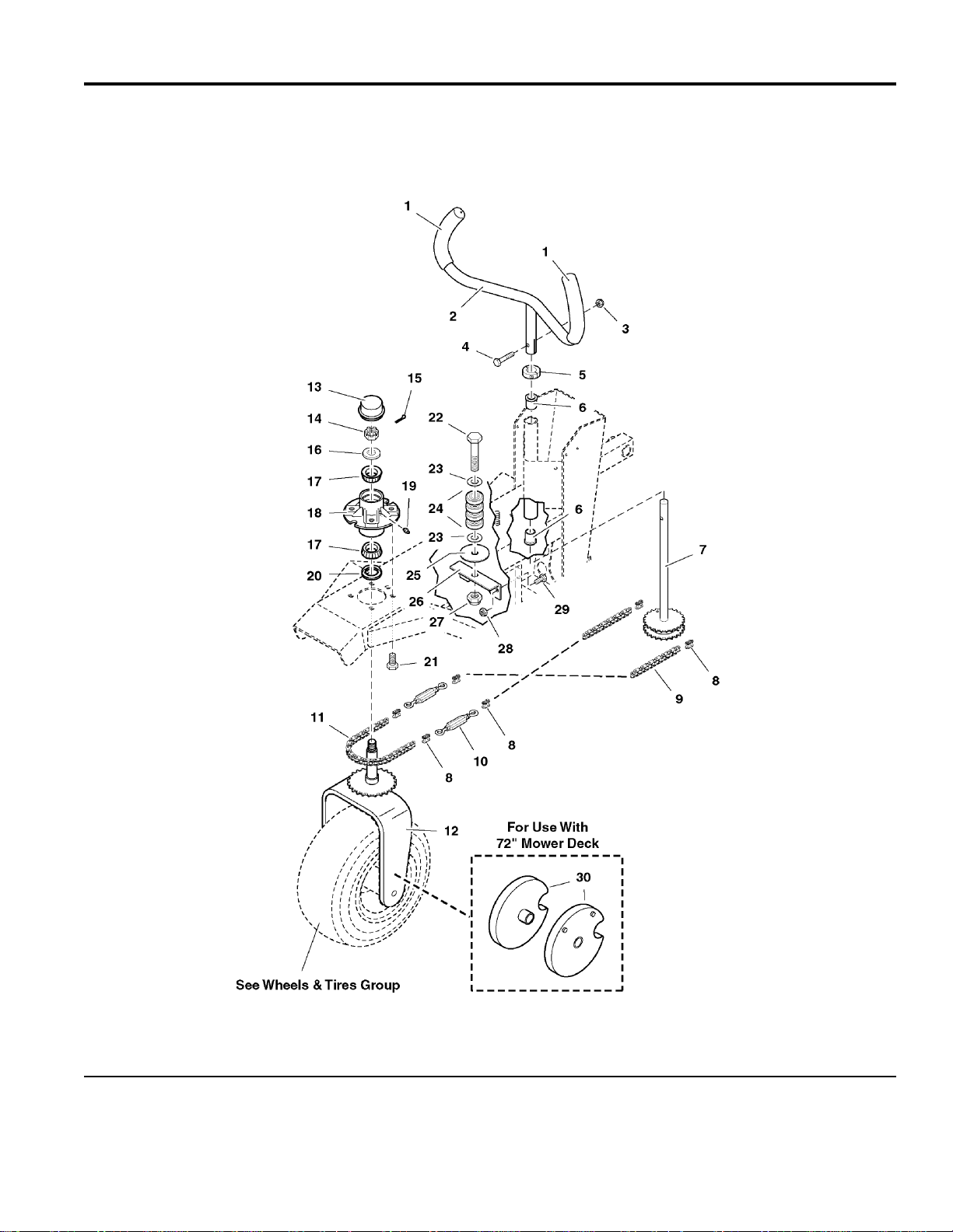
Steering Group
)
)
NOTE: Unless noted otherwise,
use the standard hardware torque
specification chart.
095STR0
The above parts group applies to the following Mfg. Nos.:
5901035 (S/N: 1023 & Above) (H3225K
5901036 (H3227K
© Copyright Ferris Industries. All Rights Reserved.
2005
4
TP 400-7095-04-H3-F
Page 5

Steering Group
)
)
PART NO. DESCRIPTIONREF NO QTY.
1 5020837 2 GRIP, Foam
2 5041770B 1 STEERING HANDLE
3 5025096 1 NUT, 3/8-16 Hex Nylon Lock
4 5025013X12 1 BOLT, 3/8-16 x 1-1/2
5 5020602 1 COLLAR, 1" Split
6 5020823 2 BUSHING, Flange
7 5042087 1 SHAFT, Steering Sprocket
8 5010674 6 CONNECTOR, #40 Chain Link
9 5010673X31 2 CHAIN, #40 Roller, 31 Links
10 5042090 2 TURNBUCKLE
11 5010673X35 1 CHAIN, #40 Roller, 35 Links
12 5042127B 1 MOUNT, Steering Tire
13 5021073 1 CAP
14 5025104 1 NUT, 3/4-16 Hex Slotted
15 5025203X10 1 COTTER PIN, 1/8" X 1-1/4"
16 5025160 1 WASHER, 3/4" SAE
17 5020884 2 BEARING, Tapered Roller
18 5042110 1 HUB, Steering
19 5020095 1 GREASE FITTING
20 5021072 1 GREASE SEAL
21 5025018X10 4 BOLT, 1/2-20 x 1-1/4
22 5025280X24 1 BOLT, 5/8-11 x 3
23 5025281 2 WASHER, 5/8" SAE
24 5021882 4 BEARING, Roller
25 5043652 1 WASHER, Chain
26 5044627B 1 MOUNT, Chain Roller
27 5025282 1 NUT, 5/8-11 Hex Jam Nylon Lock
28 5025057 2 NUT, 5/16-18 Hex Nylon Lock
29 5025011X6 2 BOLT, 5/16-18 x 3/4
30 5044372B 2 WHEEL WEIGHT (72" Deck only)
Footnotes
The above parts group applies to the following Mfg. Nos.:
5901035 (S/N: 1023 & Above) (H3225K
5901036 (H3227K
© Copyright Ferris Industries. All Rights Reserved.
2005
5
TP 400-7095-04-H3-F
Page 6
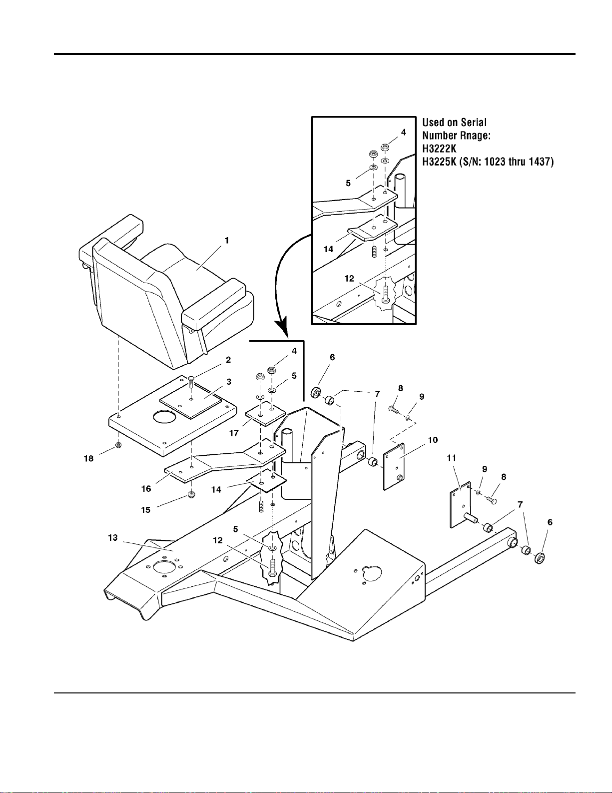
Seat & Mount Group
)
)
NOTE: Unless noted otherwise,
use the standard hardware torque
specification chart.
095STM
The above parts group applies to the following Mfg. Nos.:
5901035 (S/N: 1023 & Above) (H3225K
5901036 (H3227K
© Copyright Ferris Industries. All Rights Reserved.
2005
6
TP 400-7095-04-H3-F
Page 7

Seat & Mount Group
)
)
PART NO. DESCRIPTIONREF NO QTY.
1 5022031 1 SEAT, Gray, Complete
1 5022031X2 1 CUSHION, Bottom, Gray
1 5022031X4 1 CUSHION, Back, Gray
1 5022185 2 ARM REST, Complete
1 5020930X3 1 SEAT ADJUSTER RAILS (set of 2)
2 5025013X10 2 BOLT, 3/8-16 x 1-1/4
3 5045574B 1 PLATE, Seat Mount
4 5025094 2 NUT, 7/16-20 Hex Nylon Lock
5 5025157 2 WASHER, 7/16" SAE (H3225K, S/N: 1023 - 1437)
5 5025381 3 WASHER, 7/16" GD9 (H3225K, S/N: 1462 & above)
6 5010477 2 COLLAR, 5/8" Set
7 5020876P 4 BUSHING, Plastic
8 5025011X8 6 BOLT, 5/16-18 x 1
9 5025170 6 WASHER, 5/16" Lock
10 5045570B 1 PIVOT BRACKET-LH
11 5045571B 1 PIVOT BRACKET-RH
12 25291-14 1 BOLT, 7/16-20 x 1-3/4 (H2335K, S/N: 1023 - 1437)
12 5025380 1 BOLT, 7/16-20 x 2 (H3225K, S/N: 1438 & above)
13 5031113B 1 TRAILER FRAME
14 - 1 SUPPORT, Seat Spring (OBSOLETE, see S/N: 1438 & above for replacement
parts.)
14 5048224A 1 SHIM, Seat Spring, Lower
15 5025096 2 NUT, 3/8-16 Hex Nylon Lock
16 - 1 SEAT SPRING (OBSOLETE, see S/N: 1438 & above for replacement parts.)
16 5048222A 1 SEAT SPRING
17 5048223A 1 SHIM, Seat Spring, Upper
18 5025057 4 NUT, 5/16-18 Hex Nylon Lock
Footnotes
The above parts group applies to the following Mfg. Nos.:
5901035 (S/N: 1023 & Above) (H3225K
5901036 (H3227K
© Copyright Ferris Industries. All Rights Reserved.
2005
7
TP 400-7095-04-H3-F
Page 8
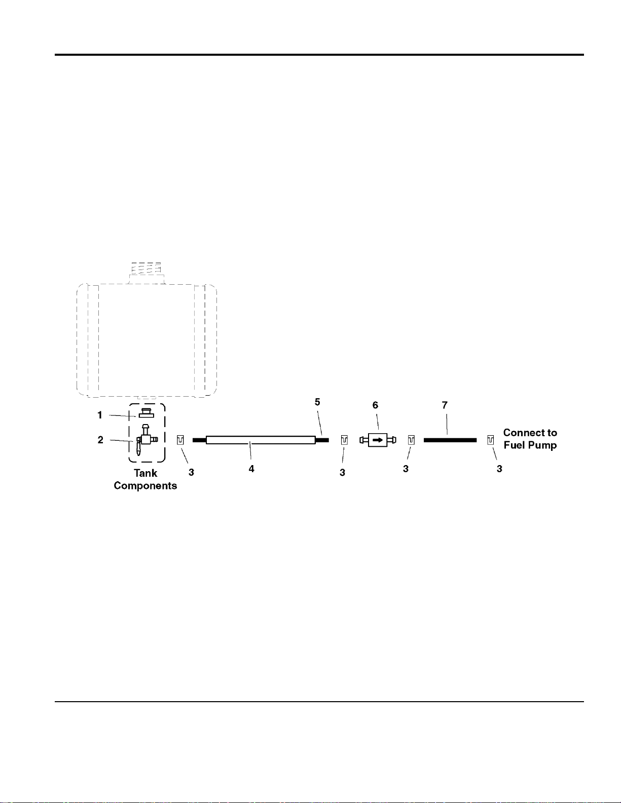
Fuel Supply Hose & Tank Replacement Part Group
)
)
NOTE: Unless noted otherwise,
use the standard hardware torque
specification chart.
095FSH0
The above parts group applies to the following Mfg. Nos.:
5901035 (S/N: 1023 & Above) (H3225K
5901036 (H3227K
© Copyright Ferris Industries. All Rights Reserved.
2005
8
TP 400-7095-04-H3-F
Page 9

Fuel Supply Hose & Tank Replacement Part Group
)
)
PART NO. DESCRIPTIONREF NO QTY.
1 5022151 1 RUBBER BUSHING
2 5022152 1 FUEL SHUTOFF VALVE
3 5020835 4 CLAMP, Hose
4 5050833X35 1 WIRE LOOM, 35"
5 50831-37 1 1/4" Fuel Line, 37" Long
6 5021178X3 1 FUEL FILTER
7 5050831X9 1 1/4" Fuel Line, 9" Long
Footnotes
The above parts group applies to the following Mfg. Nos.:
5901035 (S/N: 1023 & Above) (H3225K
5901036 (H3227K
© Copyright Ferris Industries. All Rights Reserved.
2005
9
TP 400-7095-04-H3-F
Page 10
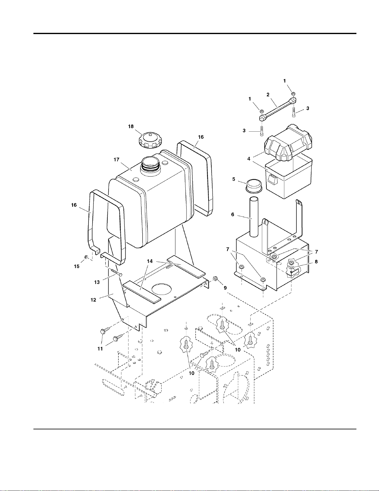
Fuel Tank & Mount Group
)
)
NOTE: Unless noted otherwise,
use the standard hardware torque
specification chart.
095TNK0
The above parts group applies to the following Mfg. Nos.:
5901035 (S/N: 1023 & Above) (H3225K
5901036 (H3227K
© Copyright Ferris Industries. All Rights Reserved.
2005
10
TP 400-7095-04-H3-F
Page 11

Fuel Tank & Mount Group
)
)
PART NO. DESCRIPTIONREF NO QTY.
1 5025271 2 NUT, #10-24 Hex Nylon Lock
2 5021670 1 RUBBER STRAP
3 5025270 2 SCREW, #10-24 x 1
4 5046188 1 BATTERY BOX
5 5021871 1 BREATHER
6 5030789 1 HYDRO TANK ASSEMBLY, Complete
6 5030774B 1 HYDRO TANK
6 21125-7 3 FOIL TAPE
7 5025127 5 NUT, 5/16-18 Hex Small Serrated Flange
8 5025155 1 WASHER, 5/16" SAE
9 5025057 1 NUT, 5/16-18 Hex Nylon Lock
10 5025011X6 5 BOLT, 5/16-18 x 3/4
11 5025059X6 2 BOLT, Self Tapping, 5/16-18 x 3/4
12 5044692B 1 FUEL TANK MOUNT
13 5025010X12 2 BOLT, 1/4-20 X 1-1/2
14 5021877 2 RUBBER PAD
15 5025126 2 NUT, 1/4-20 Hex Serrated Flange
16 5044693B 2 FUEL TANK STRAP
17 5021868 1 FUEL TANK, 6 Gallon
18 5022158 1 FUEL TANK CAP
Footnotes
The above parts group applies to the following Mfg. Nos.:
5901035 (S/N: 1023 & Above) (H3225K
5901036 (H3227K
© Copyright Ferris Industries. All Rights Reserved.
2005
11
TP 400-7095-04-H3-F
Page 12
Instrument & Control Panel Group
)
)
NOTE: Unless noted otherwise,
use the standard hardware torque
specification chart.
095INS0
The above parts group applies to the following Mfg. Nos.:
5901035 (S/N: 1023 & Above) (H3225K
5901036 (H3227K
© Copyright Ferris Industries. All Rights Reserved.
2005
12
TP 400-7095-04-H3-F
Page 13

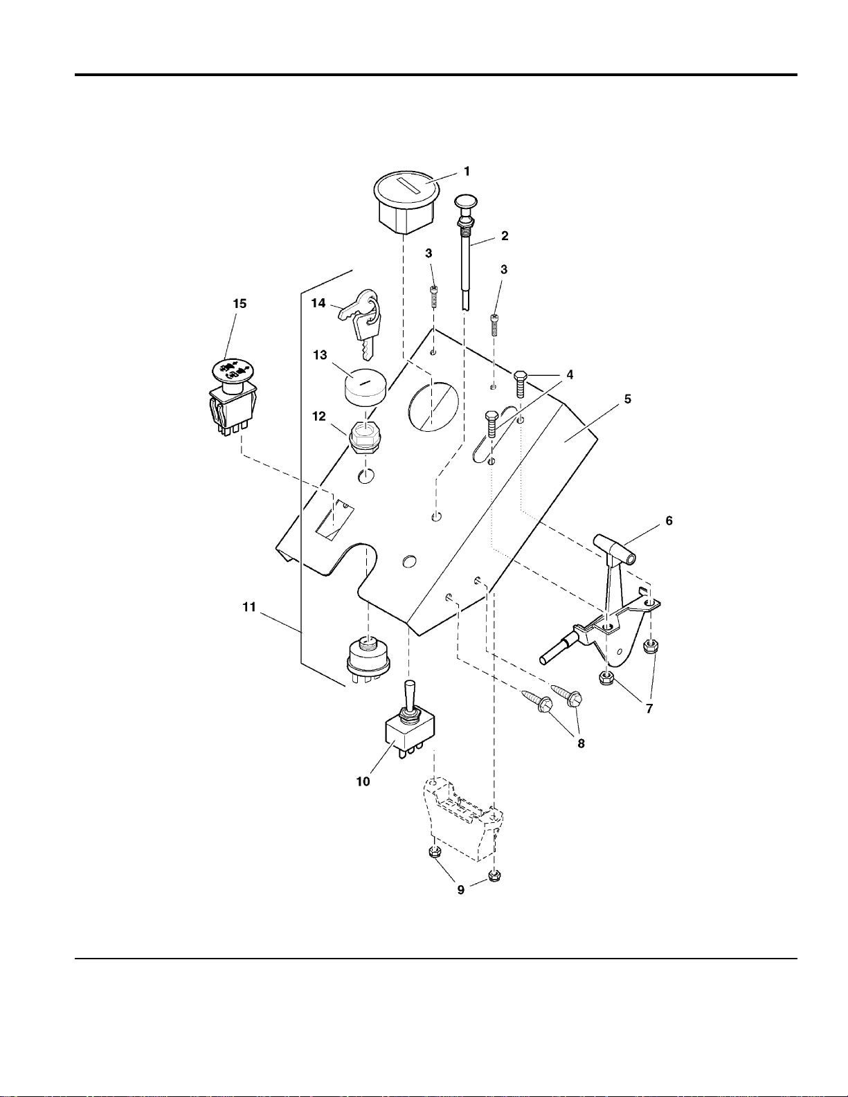
Instrument & Control Panel Group
)
)
PART NO. DESCRIPTIONREF NO QTY.
1 5020060 1 HOUR METER
2 5021663 1 CABLE, Choke Control, 57"
3 5025270 2 SCREW, #10-24 x 1
4 5025010X6 2 BOLT, 1/4-20 x 3/4
5 5045193B 1 DASH PANEL
6 5021662 1 CABLE, Throttle, 54"
7 5025095 2 NUT, 1/4-20 Hex Nylon Lock
8 5025279X6 4 BOLT, Self-Tapping, 1/4-20 x 3/4
9 5025271 2 NUT, #10-24 Hex Nylon Lock
10 5021734 1 SWITCH, Actuator
11 5020927 1 SWITCH, Ignition, Complete (Includes Ref No. 12 - 14)
12 5022791 1 PLASTIC NUT
13 5022790 1 COVER
14 5022789 1 KEY, Ignition, Molded Set
15 5022180 1 SWITCH, PTO
Footnotes
The above parts group applies to the following Mfg. Nos.:
5901035 (S/N: 1023 & Above) (H3225K
5901036 (H3227K
© Copyright Ferris Industries. All Rights Reserved.
2005
13
TP 400-7095-04-H3-F
Page 14
Engine Accessories Group
)
)
NOTE: Unless noted otherwise,
use the standard hardware torque
specification chart.
095EAC0
The above parts group applies to the following Mfg. Nos.:
5901035 (S/N: 1023 & Above) (H3225K
5901036 (H3227K
© Copyright Ferris Industries. All Rights Reserved.
2005
14
TP 400-7095-04-H3-F
Page 15

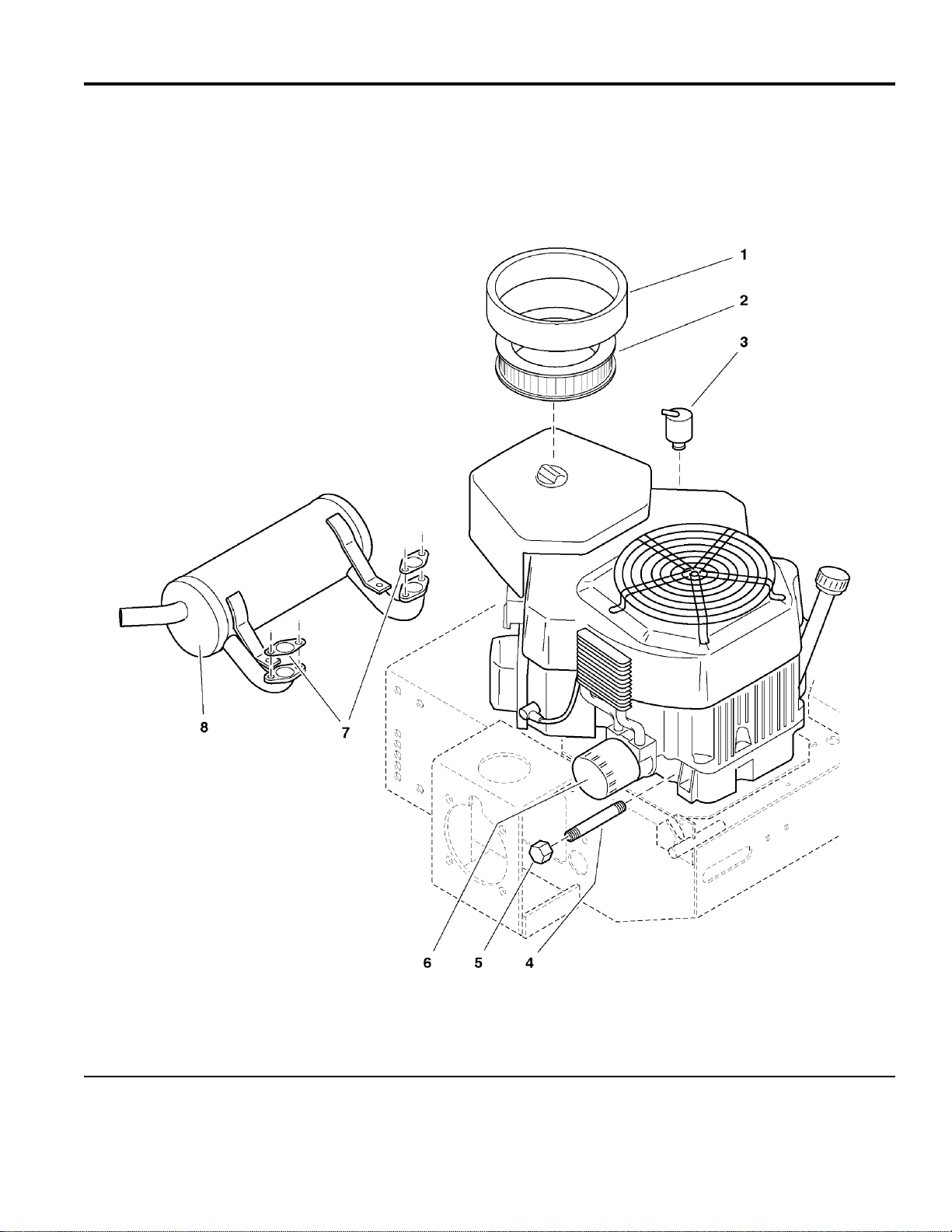
Engine Accessories Group
)
)
PART NO. DESCRIPTIONREF NO QTY.
1 5020922X4 1 PRE-CLEANER (45 083 01)
2 5020922X2 1 AIR FILTER (45 083 02)
3 - 1 BREATHER (24 755 20)
4 5021707 1 NIPPLE, 3/8 NPT X 4-1/2
5 5021466 1 CAP, 3/8 NPT
6 5021144X1 1 OIL FILTER (12 050 01)
7 - 2 GASKET (24 041 02)
8 5022161 1 MUFFLER, Kohler
Footnotes
- See your local Kohler engine dealer for service parts.
The above parts group applies to the following Mfg. Nos.:
5901035 (S/N: 1023 & Above) (H3225K
5901036 (H3227K
© Copyright Ferris Industries. All Rights Reserved.
2005
15
TP 400-7095-04-H3-F
Page 16
Engine & PTO Group - Kohler
)
)
NOTE: Unless noted otherwise,
use the standard hardware torque
specification chart.
095ENGK
The above parts group applies to the following Mfg. Nos.:
5901035 (S/N: 1023 & Above) (H3225K
5901036 (H3227K
© Copyright Ferris Industries. All Rights Reserved.
2005
16
TP 400-7095-04-H3-F
Page 17

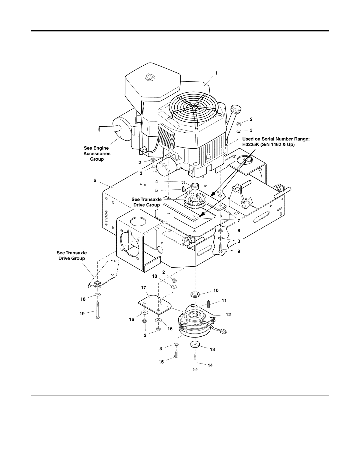
Engine & PTO Group - Kohler
)
)
PART NO. DESCRIPTIONREF NO QTY.
1 5022961 1 ENGINE, 25HP Kohler (Model CV730S) (H3225K S/N: 1462 & above)
1 5022034 1 ENGINE, 22HP Kohler (Model CV22S) (H3225K, S/N: 1023 - 1461)
1 5022069 1 ENGINE, 25HP Kohler (Model CV25S) (H3225K, S/N: 1023 - 1461)
1 5023235 1 ENGINE, 27HP Kohler (Model CV740V)
2 5025057 7 NUT, 5/16-18 Hex Nylon Lock
3 5025155 9 WASHER, 5/16" SAE
4 5042840 1 SPACER, 1.13 X 1.75 X .88 (H3225K, S/N: 1462 & above)
4 5044062 1 SPACER, 1.13 X 1.75 X .50 (H3225K, S/N: 1023 - 1461)
5 5050407X10 1 KEY, 1/4 SQ. X 5/8
6 5031130B 1 ENGINE DECK (H3225K, S/N: 1023 & Above)
7 5045352B 2 SPACER, Engine Block (H3225K, S/N: 1462 & above)
8 5025188 3 WASHER, 5/16" Internal Tooth Lock
9 5025011X14 3 BOLT, 5/16-18 x 1-3/4 (H3225K, S/N: 1462 & above)
9 5025011X10 3 BOLT, 5/16-18 x 1-1/4 (H3225K, S/N: 1023 - 1461)
10 5048135 1 SPACER, 1.13 x 1.75 x .62 (H3225K, S/N: 1462 & above)
10 5042945 1 SPACER, 1.13 x 2.00 x .19 (H3225K, S/N: 1023 - 1461)
11 5050407X1 1 KEY, 1/4 SQ. X 1
12 5021145 1 CLUTCH, Electric, 1-1/8" Shaft
13 5042132 1 SPACER, .45 x 1.62 x .37
14 5045289 1 CRANKSHAFT BOLT, 7/16 x 2-1/2 (H3225K, S/N: 1462 & above)
14 5043626 1 CRANKSHAFT BOLT, 7/16 x 3 (H3225K, S/N: 1023 - 1461)
15 5025011X6 1 BOLT, 5/16-18 x 3/4
16 5044617 2 WASHER, Clutch Anchor
17 5043636 1 CLUTCH ANCHOR PAD
18 5025164 2 WASHER, 5/16" Fender
19 25011-28 1 BOLT, 5/16-18 x 3-1/2 (H3225K, S/N: 1462 & above)
19 5025011X24 1 BOLT, 5/16-18 x 3 (H3225K, S/N: 1023 - 1461)
Footnotes
- See your local Kohler engine dealer for parts & service.
The above parts group applies to the following Mfg. Nos.:
5901035 (S/N: 1023 & Above) (H3225K
5901036 (H3227K
© Copyright Ferris Industries. All Rights Reserved.
2005
17
TP 400-7095-04-H3-F
Page 18
Pump Drive Group
)
)
NOTE: Unless noted otherwise,
use the standard hardware torque
specification chart.
095PDR0
The above parts group applies to the following Mfg. Nos.:
5901035 (S/N: 1023 & Above) (H3225K
5901036 (H3227K
© Copyright Ferris Industries. All Rights Reserved.
2005
18
TP 400-7095-04-H3-F
Page 19

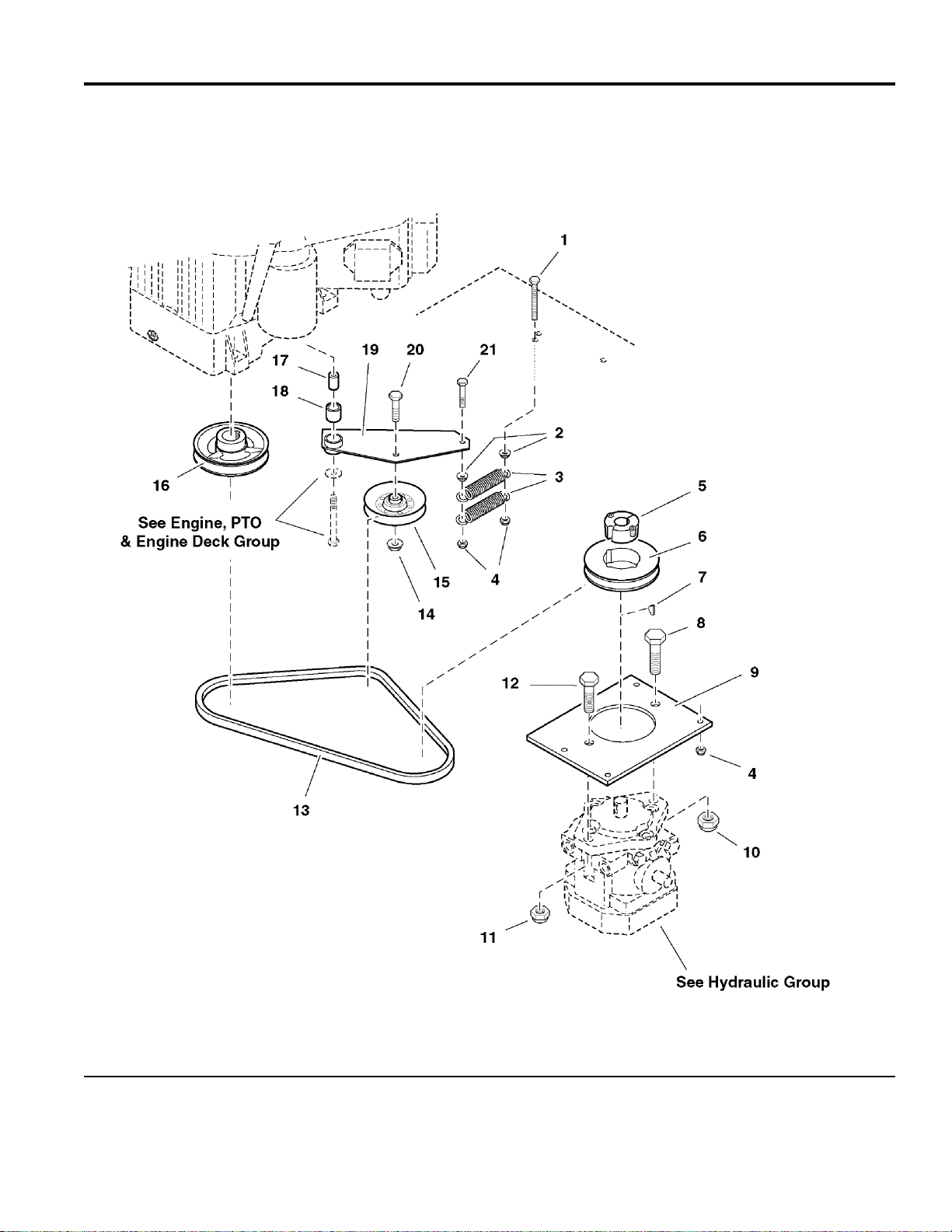
Pump Drive Group
)
)
PART NO. DESCRIPTIONREF NO QTY.
1 5025055X28 1 BOLT, 5/16-18 x 3-1/2 TFL
2 5025127 2 NUT, 5/16-18 Hex Small Serrated Flange
3 5020807 2 SPRING, Extension
4 5025057 6 NUT, 5/16-18 Hex Nylon Lock
5 5021367 1 BUSHING, Tapered Hub
6 5021681 1 PULLEY, Tapered Hub
7 5021084 1 KEY, #61 Woodruff
8 5025018X14 1 BOLT, 1/2-20 x 1-3/4
9 5044024B 1 PLATE, Pump Mount
10 5025098 1 NUT, 1/2-20 Hex Nylon Lock
11 5025125 1 NUT, 7/16-14 Hex Nylon Lock
12 25015-12 1 BOLT, 7/16-14 x 1-1/2
13 5021684 1 BELT
14 5025128 1 NUT, 3/8-16 Hex Serrated Flange
15 5044060 1 PULLEY, Idler
16 5044061 1 PULLEY, Pump Drive
17 5042134 1 SPACER, .32 x .75 x 1.06
18 5020876B 1 BUSHING, Brass
19 5044032B 1 IDLER ARM ASSEMBLY, Complete (Includes Ref No. 18)
20 5025013X14 1 BOLT, 3/8-16 x 1-3/4
21 5025011X14 1 BOLT, 5/16-18 x 1-3/4
Footnotes
The above parts group applies to the following Mfg. Nos.:
5901035 (S/N: 1023 & Above) (H3225K
5901036 (H3227K
© Copyright Ferris Industries. All Rights Reserved.
2005
19
TP 400-7095-04-H3-F
Page 20
Motion Control Group - Engine Deck
)
)
NOTE: Unless noted otherwise,
use the standard hardware torque
specification chart.
095MCGE0
The above parts group applies to the following Mfg. Nos.:
5901035 (S/N: 1023 & Above) (H3225K
5901036 (H3227K
© Copyright Ferris Industries. All Rights Reserved.
2005
20
TP 400-7095-04-H3-F
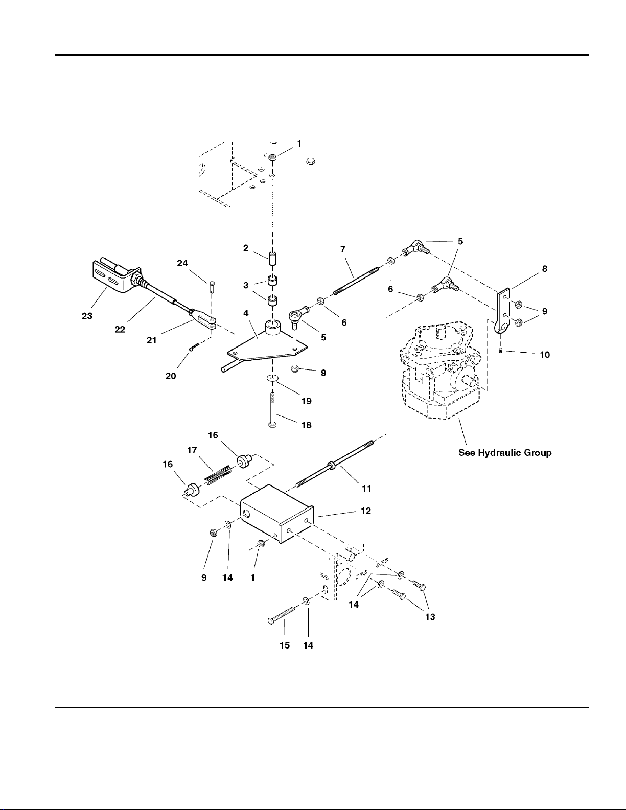
Page 21

Motion Control Group - Engine Deck
)
)
PART NO. DESCRIPTIONREF NO QTY.
1 5025057 2 NUT, 5/16-18 Hex Nylon Lock
2 5042926 1 SPACER, .33 X .75 X 1.56
3 5020043 2 BUSHING, Brass
4 5044068B 1 SPEED CONTROL PIVOT, Complete (Includes Ref No. 3)
5 5021170 3 BALL JOINT, 5/16-24 Female Studded
6 5025033 3 NUT, 5/16-24 Hex
7 5044083 1 CONTROL ROD
8 5044049B 1 LEVER, Pump Control
9 5025045 4 NUT, 5/16-24, Hex Nylon Lock
10 25272-4 1 SET SCREW, 5/16-18 x 1/2, Cone
11 5042934 1 SPRING RETURN ROD
12 5044055B 1 BOX, Spring Mount
13 5025011X8 2 BOLT, 5/16-18 x 1
14 5025155 4 WASHER, 5/16" SAE
15 5025055X28 1 BOLT, 5/16-18 x 3-1/2 TFL
16 5042911 2 GUIDE, Spring Return
17 5021354 1 SPRING, Compression
18 5025011X18 1 BOLT, 5/16-18 x 2-1/4
19 5025164 1 WASHER, 5/16" Fender
20 25204-4 1 COTTER PIN, 1/16" x 1/2"
21 5021104 1 CLEVIS, 1/4-28, Plastic
22 5021089 1 CABLE, Speed Control
23 5042170B 1 CABLE BRACKET
24 5025212X8 1 CLEVIS PIN, 1/4 x 1
Footnotes
The above parts group applies to the following Mfg. Nos.:
5901035 (S/N: 1023 & Above) (H3225K
5901036 (H3227K
© Copyright Ferris Industries. All Rights Reserved.
2005
21
TP 400-7095-04-H3-F
Page 22

Motion Control Group - Trailer
)
)
NOTE: Unless noted otherwise,
use the standard hardware torque
specification chart.
095MCGT0
The above parts group applies to the following Mfg. Nos.:
5901035 (S/N: 1023 & Above) (H3225K
5901036 (H3227K
© Copyright Ferris Industries. All Rights Reserved.
2005
22
TP 400-7095-04-H3-F
Page 23

Motion Control Group - Trailer
)
)
PART NO. DESCRIPTIONREF NO QTY.
1 5042185B 1 FOOT CONTROL PEDAL
2 5042281 1 SAFETY WALK
3 5025171 2 WASHER, 3/8" Lock
4 5025013X6 2 BOLT, 3/8-16 x 3/4
5 5025097 2 NUT, 3/8-24 Hex Nylon Lock
6 5025013X8 2 BOLT, 3/8-16 x 1
7 5042137B 1 FOOT PEDAL PIVOT MOUNT, Complete
8 5020875P 2 BUSHING, Plastic
9 5042147 1 SHAFT, Pedal Pivot
10 5025139 6 NUT, 5/16-18 Hex Large Serrated Flange
11 5025128 2 NUT, 3/8-16 Hex Serrated Flange
12 5025011X20 2 BOLT, 5/16-18 x 2-1/2
13 5021098 2 BEARING, Flange
14 25204-4 1 COTTER PIN, 1/16" x 1/2"
15 5021089 1 CABLE, Speed Control
16 5042170B 1 CABLE BRACKET
17 5025155 2 WASHER, 5/16" SAE
18 5025011X8 2 BOLT, 5/16-18 x 1
19 5021104 1 CLEVIS, 1/4-28, Plastic
20 5025212X8 1 CLEVIS PIN, 1/4 x 1
21 5025011X6 2 BOLT, 5/16-18 x 3/4
22 5042184B 1 BELL CRANK
23 5021049 1 BALL JOINT, 3/8-24 Male, Studded
24 5025035 1 NUT, 3/8-24 Hex
25 5020805 1 BALL JOINT, 3/8" Female Studded
Footnotes
The above parts group applies to the following Mfg. Nos.:
5901035 (S/N: 1023 & Above) (H3225K
5901036 (H3227K
© Copyright Ferris Industries. All Rights Reserved.
2005
23
TP 400-7095-04-H3-F
Page 24

Hydraulic Group
)
)
NOTE: Unless noted otherwise,
use the standard hardware torque
specification chart.
095HYD0
The above parts group applies to the following Mfg. Nos.:
5901035 (S/N: 1023 & Above) (H3225K
5901036 (H3227K
© Copyright Ferris Industries. All Rights Reserved.
2005
24
TP 400-7095-04-H3-F
Page 25

Hydraulic Group
)
)
PART NO. DESCRIPTIONREF NO QTY.
1 5021871 1 BREATHER
2 5030789 1 HYDRO TANK ASSEMBLY, Complete
2 5030774B 1 HYDRO TANK
2 21125-7 3 FOIL TAPE
3 5021082 1 STRAINER
4 5021233 4 FITTING, 1/2" NPT, 90 Deg.
5 5021392 10 CLAMP, #6 Hose
6 5021356 1 FILTER HEAD
7 5021363 1 FITTING, O-Ring, 90 Deg.
8 5022845 1 SPRING, Compression
9 5050848X22P75 1 HOSE, Hydraulic, 22-3/4"
10 5021357 1 FILTER
11 5050848X9P75 1 HOSE, 9-3/4"
12 5021368 1 OIL COOLER
13 5021388 1 FITTING, Reducer
14 5021370 3 FITTING, NPT - Hose, 90 Deg.
15 5050857X29 1 HOSE, 29"
16 5050857X39 1 HOSE, 29"
17 5021372 2 FITTING, 3/8NPT-1/2" Hose, Straight
18 5021373 2 FITTING, O-Ring - NPT, Swivel
19 5021333 1 HYDRAULIC PUMP
20 5021362 2 FITTING, O-Ring - NPT, 45 Deg.
21 5021361 2 FITTING, 1/2 NPT, 45 Deg. Swivel
22 5021380 1 HOSE ASSEMBLY, 19"
23 5021381 1 HOSE ASSEMBLY, 17"
24 5021636 2 PLUG, O-Ring
25 5021621 2 HYDRAULIC WHEEL MOTOR
26 5021615 2 FITTING, 7/16" O-Ring 90 Degree Swivel
27 5021616 3 FITTING, Male Adapter
28 5020835 6 CLAMP, Hose
29 5050869X25 1 HOSE, 25"
30 5021618 1 FITTING, Tee
31 5021360 2 FITTING, Tee
32 5050869X2P25 1 HOSE, 2-1/4"
33 5050869X6P25 1 HOSE, 6-1/4"
34 5021383 1 HOSE ASSEMBLY, 13"
35 5021382 1 HOSE ASSEMBLY, 15"
36 5021620 1 FITTING, O-Ring - Hose
37 5050857X10P5 1 HOSE, 10-1/2"
38 5021617 1 FITTING, Reducer
39 5021378 1 FITTING, Reducer
Footnotes
The above parts group applies to the following Mfg. Nos.:
5901035 (S/N: 1023 & Above) (H3225K
5901036 (H3227K
© Copyright Ferris Industries. All Rights Reserved.
2005
25
TP 400-7095-04-H3-F
Page 26

Hydraulic Group
)
)
NOTE: Unless noted otherwise,
use the standard hardware torque
specification chart.
095HYD0
The above parts group applies to the following Mfg. Nos.:
5901035 (S/N: 1023 & Above) (H3225K
5901036 (H3227K
© Copyright Ferris Industries. All Rights Reserved.
2005
26
TP 400-7095-04-H3-F
Page 27

Hydraulic Group
)
)
PART NO. DESCRIPTIONREF NO QTY.
40 5021376 1 FITTING, Tee
41 5021377 1 FITTING, Straight Swivel
Footnotes
The above parts group applies to the following Mfg. Nos.:
5901035 (S/N: 1023 & Above) (H3225K
5901036 (H3227K
© Copyright Ferris Industries. All Rights Reserved.
2005
27
TP 400-7095-04-H3-F
Page 28

Parking Brake Group
)
)
NOTE: Unless noted otherwise,
use the standard hardware torque
specification chart.
095PBR0
The above parts group applies to the following Mfg. Nos.:
5901035 (S/N: 1023 & Above) (H3225K
5901036 (H3227K
© Copyright Ferris Industries. All Rights Reserved.
2005
28
TP 400-7095-04-H3-F
Page 29

Parking Brake Group
)
)
PART NO. DESCRIPTIONREF NO QTY.
1 5021733 1 KNOB
2 5030919B 1 PARKING BRAKE LEVER
3 5025281 1 WASHER, 5/8" SAE
4 5025203X10 3 COTTER PIN, 1/8" X 1-1/4"
5 5043972B 1 BRAKE LOCK LINK
6 5044043B 1 BRAKE LINK
7 5020047 2 COLLAR, 5/16" Set
8 5025201X6 3 COTTER PIN, 3/32" x 3/4"
9 5025158 4 WASHER, 1/2" SAE
10 5025232X10 2 CLEVIS PIN, 1/2" x 1-1/4"
11 5021685 2 BRAKE LEVER
12 5044425B 2 BRAKE TUBE
13 5044422 2 BRAKE SPRING ROD
14 5025156 4 WASHER, 3/8" SAE
15 5021773 2 SPRING, Compression
16 5025097 2 NUT, 3/8-24 Hex Nylon Lock
17 5025035 4 NUT, 3/8-24 Hex
18 5021171 2 CLEVIS, 3/8-24, Plastic
19 5025214X9 2 CLEVIS PIN, 3/8 x 1-1/8
20 5021124 2 BALL JOINT, 3/8-24 Male
21 5025126 4 NUT, 1/4-20 Hex Serrated Flange
22 5025010X6 4 BOLT, 1/4-20 x 3/4
23 5025098 8 NUT, 1/2-20 Hex Nylon Lock
24 5010477 2 COLLAR, 5/8" Set
25 5020014 2 5/8" Triangle Bearing
26 5025139 1 NUT, 5/16-18 Hex Large Serrated Flange
27 5025164 3 WASHER, 5/16" Fender
28 5042317B 1 NEUTRAL LOCK LEVER, Complete (Includes Ref No. 29)
29 5020876B 1 BUSHING, Brass
30 5042134 1 SPACER, .32 x .75 x 1.06
31 5025011X16 1 BOLT, 5/16-18 x 2
32 5021146 1 BALL JOINT, 5/16-24 Female
33 5025155 3 WASHER, 5/16" SAE
34 5030911B 1 BRAKE SHAFT
35 25029 2 NUT, #10-24 Hex
36 5022095 1 SWITCH, Plunger, NO/NC
37 25179-6 2 SCREW, #10-24 x 3/4
Footnotes
The above parts group applies to the following Mfg. Nos.:
5901035 (S/N: 1023 & Above) (H3225K
5901036 (H3227K
© Copyright Ferris Industries. All Rights Reserved.
2005
29
TP 400-7095-04-H3-F
Page 30

Deck Lift Group
)
)
NOTE: Unless noted otherwise,
use the standard hardware torque
specification chart.
095DLT0
The above parts group applies to the following Mfg. Nos.:
5901035 (S/N: 1023 & Above) (H3225K
5901036 (H3227K
© Copyright Ferris Industries. All Rights Reserved.
2005
30
TP 400-7095-04-H3-F
Page 31

Deck Lift Group
)
)
PART NO. DESCRIPTIONREF NO QTY.
1 5020959 1 RUBBER STRAP
2 5025154 2 WASHER, 1/4" SAE
3 5025095 2 NUT, 1/4-20 Hex Nylon Lock
4 5025010X8 2 BOLT, 1/4-20 x 1
5 5025013X8 2 BOLT, 3/8-16 x 1
6 5043536 1 ELECTRIC ACTUATOR
7 5044082 2 ACTUATOR MOUNT
8 5043688 1 PIN, Clevis
9 5043677 2 ACTUATOR LINK, Lower
10 5025214X8 1 CLEVIS PIN, 3/8 x 1
11 5025203X10 2 COTTER PIN, 1/8" X 1-1/4"
12 5025281 1 WASHER, 5/8" SAE
13 5044618 2 ACTUATOR LINK, Upper
14 5041477 2 SPACER, .63 x 1.06 x .23
15 5025201X6 1 COTTER PIN, 3/32" x 3/4"
Footnotes
The above parts group applies to the following Mfg. Nos.:
5901035 (S/N: 1023 & Above) (H3225K
5901036 (H3227K
© Copyright Ferris Industries. All Rights Reserved.
2005
31
TP 400-7095-04-H3-F
Page 32

Tire & Wheel Group
)
)
NOTE: Unless noted otherwise,
use the standard hardware torque
specification chart.
095WHL0
The above parts group applies to the following Mfg. Nos.:
5901035 (S/N: 1023 & Above) (H3225K
5901036 (H3227K
© Copyright Ferris Industries. All Rights Reserved.
2005
32
TP 400-7095-04-H3-F
Page 33

Tire & Wheel Group
)
)
PART NO. DESCRIPTIONREF NO QTY.
1 5021150S 1 WHEEL & TIRE ASSEMBLY, 18 x 7.5 x 8, Silver, Complete (Includes Ref No. 2 -
6)
1 5021150 1 WHEEL & TIRE ASSEMBLY, 18 x 7.5 x 8, White, Complete (Includes Ref No. 2 -
6)
2 5021215 1 TIRE, Rear, 18 x 7.5 x 8
3 21216S 1 WHEEL ASSEMBLY, 8 x 3.75, Silver, Complete (Includes Ref No. 4 - 6)
3 5021216 1 WHEEL ASSEMBLY, 8 x 3.75, White, Complete (Includes Ref No. 4 - 6)
4 5020883 2 BEARING CUP
5 5020884 2 BEARING, Tapered Roller
6 5020885 2 GREASE SEAL
7 5042314 1 STEERING TIRE AXLE
8 5042315 2 SPACER, 1.01 X 1.25 X 2.06
9 5025019X76 1 BOLT, 5/8-11 x 9-1/2
10 5025103 1 NUT, 5/8-11 Hex Side Lock
11 5021353S 2 WHEEL & TIRE ASSEMBLY, 23 x 10.5-12, Silver, Complete (Includes Ref No. 12
& 13)
11 5021353 2 WHEEL & TIRE ASSEMBLY, 23 x 10.5-12, White, Complete (Includes Ref No. 12
& 13)
12 5021353X1 2 TIRE, 23 x 10.5-12
13 5021353SX2 2 WHEEL ASSEMBLY, Silver
13 5021353X2 2 WHEEL ASSEMBLY, White
14 5020601 10 LUG NUT, 1/2-20
Footnotes
The above parts group applies to the following Mfg. Nos.:
5901035 (S/N: 1023 & Above) (H3225K
5901036 (H3227K
© Copyright Ferris Industries. All Rights Reserved.
2005
33
TP 400-7095-04-H3-F
Page 34

Decal Group - Brand & Model
)
)
NOTE: Unless noted otherwise,
use the standard hardware torque
specification chart.
095DCLB
The above parts group applies to the following Mfg. Nos.:
5901035 (S/N: 1023 & Above) (H3225K
5901036 (H3227K
© Copyright Ferris Industries. All Rights Reserved.
2005
34
TP 400-7095-04-H3-F
Page 35

Decal Group - Brand & Model
)
)
PART NO. DESCRIPTIONREF NO QTY.
1 5020852 2 DECAL, Ferris Logo, 10-3/4"
2 5021126 1 DECAL, Hydro Drive
3 5020846 1 DECAL, Commercial
4 5021300 1 DECAL, ProCut
4 5022292 1 DECAL, ProCut 32
5 5021302 1 DECAL, 61"
6 5021416 2 DECAL, 72"
7 5022227 1 DECAL, Ferris Logo, 6-3/8"
8 5022229 1 DECAL, Number One In Reliability
9 5022240 1 DECAL, Ferris Text
10 5022547 1 DECAL, Ferris Logo (72" deck)
11 5022545 1 DECAL, Ferris Logo (61" deck)
12 5022548 1 DECAL, ProCut 3072
13 5022546 1 DECAL ProCut 3061
14 5022560 1 DECAL, Ferris Text Logo
15 5022227 1 DECAL, Ferris Logo, 6-3/8"
Footnotes
The above parts group applies to the following Mfg. Nos.:
5901035 (S/N: 1023 & Above) (H3225K
5901036 (H3227K
© Copyright Ferris Industries. All Rights Reserved.
2005
35
TP 400-7095-04-H3-F
Page 36

Decal Group - Safety & Operation
)
)
NOTE: Unless noted otherwise,
use the standard hardware torque
specification chart.
095DCLS
The above parts group applies to the following Mfg. Nos.:
5901035 (S/N: 1023 & Above) (H3225K
5901036 (H3227K
© Copyright Ferris Industries. All Rights Reserved.
2005
36
TP 400-7095-04-H3-F
Page 37

Decal Group - Safety & Operation
)
)
PART NO. DESCRIPTIONREF NO QTY.
1 5022195 1 DECAL, Dash
2 5020850 1 DECAL, WARNING Operation
3 1704277 1 DECAL, Danger (Chute In Place)
4 1704276 1 DECAL, Danger (Hand Under Deck)
5 5021818 1 DECAL, Warning, Machine Will Climb
6 5021111 1 DECAL, Speed Control
7 5021109 1 DECAL, Parking Brake
8 5044449 1 DECAL, Oil Reservoir
9 5020337 1 DECAL, Warning
10 5021036 2 DECAL, Grease Daily
11 5020851 3 DECAL, Danger
12 - 2 TAG, MODEL/SERIAL (Not Serviced) (Not a serviceable part)
13 - 1 DECAL, Patent Number (Not Serviced) (Not a serviceable part)
Footnotes
The above parts group applies to the following Mfg. Nos.:
5901035 (S/N: 1023 & Above) (H3225K
5901036 (H3227K
© Copyright Ferris Industries. All Rights Reserved.
2005
37
TP 400-7095-04-H3-F
Page 38

Oil Cooler Mount Group
)
)
NOTE: Unless noted otherwise,
use the standard hardware torque
specification chart.
095CLR0
The above parts group applies to the following Mfg. Nos.:
5901035 (S/N: 1023 & Above) (H3225K
5901036 (H3227K
© Copyright Ferris Industries. All Rights Reserved.
2005
38
TP 400-7095-04-H3-F
Page 39

Oil Cooler Mount Group
)
)
PART NO. DESCRIPTIONREF NO QTY.
1 5042951B 1 OIL COOLER HOOD
2 5025010X12 6 BOLT, 1/4-20 X 1-1/2
3 5044735 2 SPACER, .27 x .75 x .94
4 5021686 2 CAP
5 5025095 6 NUT, 1/4-20 Hex Nylon Lock
6 5044065B 1 OIL COOLER MOUNT - RH
7 5025011X12 2 BOLT, 5/16-18 x 1-1/2
8 5025011X8 2 BOLT, 5/16-18 x 1
9 5044148B 1 OIL COOLER MOUNT - LH
10 5044075B 1 OIL COOLER MOUNT
11 5022153 4 MOUNT KIT
Footnotes
The above parts group applies to the following Mfg. Nos.:
5901035 (S/N: 1023 & Above) (H3225K
5901036 (H3227K
© Copyright Ferris Industries. All Rights Reserved.
2005
39
TP 400-7095-04-H3-F
Page 40

Operator Presence Group
)
)
NOTE: Unless noted otherwise,
use the standard hardware torque
specification chart.
095OPS0
The above parts group applies to the following Mfg. Nos.:
5901035 (S/N: 1023 & Above) (H3225K
5901036 (H3227K
© Copyright Ferris Industries. All Rights Reserved.
2005
40
TP 400-7095-04-H3-F
Page 41

Operator Presence Group
)
)
PART NO. DESCRIPTIONREF NO QTY.
1 5045196B 1 OPERATOR PRESENCE PLATE
2 5022200 1 SAFETY WALK
3 5025011X16 1 BOLT, 5/16-18 x 2
4 5043296 1 BUSHING, Brass
5 5022198 1 SWITCH, Plunger, Snap-In, NO/NO
6 5025164 1 WASHER, 5/16" Fender
7 5025057 1 NUT, 5/16-18 Hex Nylon Lock
8 5025096 2 NUT, 3/8-16 Hex Nylon Lock
9 5025156 2 WASHER, 3/8" SAE
10 5021102 2 SPRING, Compression
11 5025128 1 NUT, 3/8-16 Hex Serrated Flange
12 5020880 1 INSERT, Bearing
13 5025013X28 2 BOLT, 3/8-16 x 3-1/2
14 5025013X8 1 BOLT, 3/8-16 x 1
Footnotes
The above parts group applies to the following Mfg. Nos.:
5901035 (S/N: 1023 & Above) (H3225K
5901036 (H3227K
© Copyright Ferris Industries. All Rights Reserved.
2005
41
TP 400-7095-04-H3-F
Page 42

61" Mower Deck - Housing, Covers, Spindles & Blades
)
NOTE: Unless noted otherwise,
use the standard hardware torque
specification chart.
0956HC0
The above parts group applies to the following Mfg. Nos.:
5900227 (S/N: 1022 & Above) (P61
© Copyright Ferris Industries. All Rights Reserved.
2005
42
TP 400-7095-04-H3-F
Page 43

61" Mower Deck - Housing, Covers, Spindles & Blades
)
PART NO. DESCRIPTIONREF NO QTY.
1 5041668B 1 DISCHARGE CHUTE
2 5025011X8 2 BOLT, 5/16-18 x 1
3 5025057 2 NUT, 5/16-18 Hex Nylon Lock
4 5030822B 1 61" SPINDLE COVER
5 5025098 8 NUT, 1/2-20 Hex Nylon Lock
6 5025158 8 WASHER, 1/2" SAE
7 5025018X10 8 BOLT, 1/2-20 x 1-1/4
8 5041477 18 SPACER, .63 x 1.06 x .23
9 5025040 3 NUT, 5/8-11 Hex
10 5020841X1 3 RUBBER LATCH
11 5020841X4 3 CLEVIS PIN
12 5020841X5 3 COTTER PIN
13 5025057 12 NUT, 5/16-18 Hex Nylon Lock
14 5050407X9 3 KEY, 1/4 SQ. X 2-1/2
15 5030301 3 SPINDLE ASSEMBLY, Complete
16 5041480 3 SPINDLE SHAFT
17 5020864 6 SNAP RING, External
18 5020866 6 SNAP RING, Internal
19 5041653 3 SPINDLE WASHER, Top
20 5020828 6 BEARING
21 5030293 3 SPINDLE HOUSING
22 5020095 3 GREASE FITTING
23 5041672 3 SPINDLE WASHER, Bottom
24 5023156 12 BOLT, Flange Head, 5/16-18 x 1-1/4
25 5020842 3 MOWER BLADE, 21"
26 5025159 3 WASHER, 5/8" USS
27 5025019X76 3 BOLT, 5/8-11 x 9-1/2
28 6630821 1 61" MOWER HOUSING ASSEMBLY (Includes safety decals)
Footnotes
The above parts group applies to the following Mfg. Nos.:
5900227 (S/N: 1022 & Above) (P61
© Copyright Ferris Industries. All Rights Reserved.
2005
43
TP 400-7095-04-H3-F
Page 44

61" Mower Deck - Pulleys, Belt & Idler Arm
)
NOTE: Unless noted otherwise,
use the standard hardware torque
specification chart.
0956PB0
The above parts group applies to the following Mfg. Nos.:
5900227 (S/N: 1022 & Above) (P61
© Copyright Ferris Industries. All Rights Reserved.
2005
44
TP 400-7095-04-H3-F
Page 45

61" Mower Deck - Pulleys, Belt & Idler Arm
)
PART NO. DESCRIPTIONREF NO QTY.
1 5020824 1 BELT, Blade Spindle
2 5021679 1 BELT, Deck Drive
3 5025011X14 1 BOLT, 5/16-18 x 1-3/4
4 5025164 1 WASHER, 5/16" Fender
5 5042134 1 SPACER, .32 x .75 x 1.06
6 5020876B 1 BUSHING, Brass
7 5042145B 1 IDLER ARM, Complete
8 5025018X16 1 BOLT, 1/2-20 x 2
9 5025158 4 WASHER, 1/2" SAE
10 5021097 1 PULLEY, V-Idler
11 5025128 3 NUT, 3/8-16 Hex Serrated Flange
12 5025098 2 NUT, 1/2-20 Hex Nylon Lock
13 5021103 1 SPRING, Extension
14 5025156 2 WASHER, 3/8" SAE
15 5025013X16 1 BOLT, 3/8-16 x 2
16 5025141 1 EYEBOLT
17 5025032 1 NUT, 5/16-18 Hex
18 5025013X8 1 BOLT, 3/8-16 x 1
19 5025057 2 NUT, 5/16-18 Hex Nylon Lock
20 5042142B 1 SPRING ANCHOR
21 5025018X18 2 BOLT, 1/2-20 x 2-1/4
22 5021096 1 PULLEY, Backside Idler
23 5025173 1 WASHER, 1/2" Lock
24 5030819 1 IDLER PULLEY, Complete
25 5020865 2 SNAP RING, Internal
26 5020870 2 INSERT, Bearing
27 5020827 2 BEARING
28 5041481 1 PULLEY, Idler
29 5025150 1 WASHER, 1/2" USS
30 5044609 1 SPACER, .52 X 1.00 X .38
31 5025016X14 1 BOLT, 7/16-20 X 1-3/4
32 5025157 2 WASHER, 7/16" SAE
33 5021811 1 EYEBOLT, 3/8" x 8"
34 5044610B 1 ARM, Idler
35 5025094 1 NUT, 7/16-20 Hex Nylon Lock
36 5025096 1 NUT, 3/8-16 Hex Nylon Lock
37 5025010X8 6 BOLT, 1/4-20 x 1
38 5020819 3 BUSHING, Tapered Hub
39 5020814 2 PULLEY, Spindle
40 5020815 1 PULLEY, Spindle
41 5022160 1 BUSHING, Taper Lock
Footnotes
The above parts group applies to the following Mfg. Nos.:
5900227 (S/N: 1022 & Above) (P61
© Copyright Ferris Industries. All Rights Reserved.
2005
45
TP 400-7095-04-H3-F
Page 46

61" Mower Deck - Pulleys, Belt & Idler Arm
)
NOTE: Unless noted otherwise,
use the standard hardware torque
specification chart.
0956PB0
The above parts group applies to the following Mfg. Nos.:
5900227 (S/N: 1022 & Above) (P61
© Copyright Ferris Industries. All Rights Reserved.
2005
46
TP 400-7095-04-H3-F
Page 47

61" Mower Deck - Pulleys, Belt & Idler Arm
)
PART NO. DESCRIPTIONREF NO QTY.
42 5022159 1 PULLEY, Taper Lock
Footnotes
The above parts group applies to the following Mfg. Nos.:
5900227 (S/N: 1022 & Above) (P61
© Copyright Ferris Industries. All Rights Reserved.
2005
47
TP 400-7095-04-H3-F
Page 48

61" Mower Deck - Rollers & Casters
)
NOTE: Unless noted otherwise,
use the standard hardware torque
specification chart.
0956RL0
The above parts group applies to the following Mfg. Nos.:
5900227 (S/N: 1022 & Above) (P61
© Copyright Ferris Industries. All Rights Reserved.
2005
48
TP 400-7095-04-H3-F
Page 49

61" Mower Deck - Rollers & Casters
)
PART NO. DESCRIPTIONREF NO QTY.
1 5020655 2 PIN, Lynch
2 5041476 6 SPACER, 1.02 x 1.56 x .50
3 5021541 4 BUSHING, Flange
4 5020095 2 GREASE FITTING
5 5043887 2 CASTER MOUNT, Complete (Includes Ref No. 3 & 4)
6 5025011X6 6 BOLT, 5/16-18 x 3/4
7 5025139 6 NUT, 5/16-18 Hex Large Serrated Flange
8 5041702B 2 YOKE, Caster
9 5025128 1 NUT, 3/8-16 Hex Serrated Flange
10 5041653 1 SPINDLE WASHER, Top
11 5025013X6 1 BOLT, 3/8-16 x 3/4
12 5020785 1 ROLLER
13 5025056 2 NUT, 1/2-13 Hex Nylon Lock
14 5021181S 2 WHEEL & TIRE ASSEMBLY, Silver, 9 x 3.5 x 4, Complete (Includes Ref No. 15 -
19)
14 5021181 2 WHEEL & TIRE ASSEMBLY, White, 9 x 3.5 x 4, Complete (Includes Ref No. 15 -
19)
15 5021181X1 2 TIRE, Front, 9 x 3.5 x 4
16 5021181X2 2 TUBE
17 5021181SX3 2 HUB & BEARING ASSEMBLY, Complete, Silver (Includes Ref No. 18 & 19)
17 5021181X3 2 HUB & BEARING ASSEMBLY, Complete, White (Includes Ref No. 18 & 19)
18 5021182 2 BEARING, Roller (1 per tire)
19 5021043 4 RETAINER, Bearing (2 per tire)
20 5041657 2 AXLE, Caster Wheel
21 5025017X44 2 BOLT, 1/2-13 x 5-1/2
Footnotes
The above parts group applies to the following Mfg. Nos.:
5900227 (S/N: 1022 & Above) (P61
© Copyright Ferris Industries. All Rights Reserved.
2005
49
TP 400-7095-04-H3-F
Page 50

72" Mower Deck - Housing, Covers, Spindles & Blades
)
NOTE: Unless noted otherwise,
use the standard hardware torque
specification chart.
0957HC0
The above parts group applies to the following Mfg. Nos.:
5900228 (S/N: 1022 & Above) (P72
© Copyright Ferris Industries. All Rights Reserved.
2005
50
TP 400-7095-04-H3-F
Page 51

72" Mower Deck - Housing, Covers, Spindles & Blades
)
PART NO. DESCRIPTIONREF NO QTY.
1 5044197B 1 DISCHARGE CHUTE
2 5025011X8 2 BOLT, 5/16-18 x 1
3 5025057 2 NUT, 5/16-18 Hex Nylon Lock
4 5049035B 1 SPINDLE COVER, RH
5 5021674 2 VINYL CAP
6 5044198B 1 CENTER DECK GUARD
7 5044180B 1 SPINDLE COVER-LH
8 5020841X4 3 CLEVIS PIN
9 5020841X1 3 RUBBER LATCH
10 5020841X5 3 COTTER PIN
11 5025040 3 NUT, 5/8-11 Hex
12 5041477 18 SPACER, .63 x 1.06 x .23
13 5025057 12 NUT, 5/16-18 Hex Nylon Lock
14 5050407X9 3 KEY, 1/4 SQ. X 2-1/2
15 5030301 3 SPINDLE ASSEMBLY, Complete
16 5041480 3 SPINDLE SHAFT
17 5020864 6 SNAP RING, External
18 5020866 6 SNAP RING, Internal
19 5041653 3 SPINDLE WASHER, Top
20 5020828 6 BEARING
21 5030293 3 SPINDLE HOUSING
22 5020095 3 GREASE FITTING
23 5041672 3 SPINDLE WASHER, Bottom
24 5023157 12 BOLT, Flange Head, 5/16-18 x 1-1/2
25 5021408 3 MOWER BLADE, 24-1/2"
26 5025159 3 WASHER, 5/8" USS
27 5025019X76 3 BOLT, 5/8-11 x 9-1/2
28 6630837 1 72" MOWER HOUSING ASSEMBLY (Includes safety decals)
Footnotes
The above parts group applies to the following Mfg. Nos.:
5900228 (S/N: 1022 & Above) (P72
© Copyright Ferris Industries. All Rights Reserved.
2005
51
TP 400-7095-04-H3-F
Page 52

72" Mower Deck - Pulleys, Belt & Idler Arm
)
NOTE: Unless noted otherwise,
use the standard hardware torque
specification chart.
0957PB0
The above parts group applies to the following Mfg. Nos.:
5900228 (S/N: 1022 & Above) (P72
© Copyright Ferris Industries. All Rights Reserved.
2005
52
TP 400-7095-04-H3-F
Page 53

72" Mower Deck - Pulleys, Belt & Idler Arm
)
PART NO. DESCRIPTIONREF NO QTY.
1 5021724 1 BELT
2 5025018X20 2 BOLT, 1/2-20 x 2-1/2
3 5025158 3 WASHER, 1/2" SAE
4 5044443 1 IDLER PULLEY
5 5025013X12 1 BOLT, 3/8-16 x 1-1/2
6 5025011X14 1 BOLT, 5/16-18 x 1-3/4
7 5025164 1 WASHER, 5/16" Fender
8 5042134 1 SPACER, .32 x .75 x 1.06
9 5020876B 1 BUSHING, Brass
10 5043007B 1 IDLER ARM, Complete (Includes Ref No. 9)
11 5025128 5 NUT, 3/8-16 Hex Serrated Flange
12 5025098 2 NUT, 1/2-20 Hex Nylon Lock
13 5021826 1 SPRING, Extension
14 5025096 1 NUT, 3/8-16 Hex Nylon Lock
15 5025013X16 1 BOLT, 3/8-16 x 2
16 5025013X8 2 BOLT, 3/8-16 x 1
17 5044174B 1 IDLER MOUNT
18 5044696 1 SPACER, .52 x 1.00 x .56
19 5025057 1 NUT, 5/16-18 Hex Nylon Lock
20 5025017X36 1 BOLT, 1/2-13 x 4-1/2
21 5021831 2 PULLEY, Idler
22 5044695 1 SPACER, .52 X 1.00 X 1.81
23 5043652 1 WASHER, Chain
24 5025056 1 NUT, 1/2-13 Hex Nylon Lock
25 5025010X8 6 BOLT, 1/4-20 x 1
26 5020819 3 BUSHING, Tapered Hub
27 5021410 3 PULLEY, Spindle
Footnotes
The above parts group applies to the following Mfg. Nos.:
5900228 (S/N: 1022 & Above) (P72
© Copyright Ferris Industries. All Rights Reserved.
2005
53
TP 400-7095-04-H3-F
Page 54

72" Mower Deck - Rollers & Casters
)
NOTE: Unless noted otherwise,
use the standard hardware torque
specification chart.
0957RL0
The above parts group applies to the following Mfg. Nos.:
5900228 (S/N: 1022 & Above) (P72
© Copyright Ferris Industries. All Rights Reserved.
2005
54
TP 400-7095-04-H3-F
Page 55

72" Mower Deck - Rollers & Casters
)
PART NO. DESCRIPTIONREF NO QTY.
1 5044257 1 CASTER MOUNT FRAME, Complete (Includes Ref. No 28 & 29)
2 5025098 8 NUT, 1/2-20 Hex Nylon Lock
3 5025158 6 WASHER, 1/2" SAE
4 5025018X10 6 BOLT, 1/2-20 x 1-1/4
5 5044166 2 DECK MOUNT SPACER
6 5044167 2 WASHER
7 5025018X20 2 BOLT, 1/2-20 x 2-1/2
8 5025017X28 2 BOLT, 1/2-13 x 3-1/2
9 5025158 4 WASHER, 1/2" SAE
10 5025056 6 NUT, 1/2-13 Hex Nylon Lock
11 5044199 2 DECK HANGER
12 5025038 2 NUT, 1/2-13 Hex
13 5025150 4 WASHER, 1/2" USS
14 5025017X44 2 BOLT, 1/2-13 x 5-1/2
15 5041657 2 AXLE, Caster Wheel
16 5021181S 2 WHEEL & TIRE ASSEMBLY, Silver, 9 x 3.5 x 4, Complete (Includes Ref No. 17 -
21)
16 5021181 2 WHEEL & TIRE ASSEMBLY, White, 9 x 3.5 x 4, Complete (Includes Ref No. 17 -
21)
17 5021181X1 2 TIRE, Front, 9 x 3.5 x 4
18 5021181X2 2 TUBE
19 5021181SX3 2 HUB & BEARING ASSEMBLY, Complete, Silver (Includes Ref No. 20 & 21)
19 5021181X3 2 HUB & BEARING ASSEMBLY, Complete, White (Includes Ref No. 20 & 21)
20 5021182 2 BEARING, Roller (1 per tire)
21 5021043 4 RETAINER, Bearing (2 per tire)
22 20784 1 Mower Seat
23 5025013X6 1 BOLT, 3/8-16 x 3/4
24 5041653 1 SPINDLE WASHER, Top
25 5025128 1 NUT, 3/8-16 Hex Serrated Flange
26 5041702B 2 YOKE, Caster
27 5041476 6 SPACER, 1.02 x 1.56 x .50
28 5021541 4 BUSHING, Flange
29 5020095 2 GREASE FITTING
30 5020655 2 PIN, Lynch
Footnotes
The above parts group applies to the following Mfg. Nos.:
5900228 (S/N: 1022 & Above) (P72
© Copyright Ferris Industries. All Rights Reserved.
2005
55
TP 400-7095-04-H3-F
Page 56

Electrical Schematic - Charging Circuit - Kohler
)
)
(S/N: 11581 & below)
094eskc0
The above parts group applies to the following Mfg. Nos.:
5901035 (S/N: 1023 & Above) (H3225K
5901036 (H3227K
© Copyright Ferris Industries. All Rights Reserved.
2005
56
TP 400-7095-04-H3-F
Page 57

Electrical Schematic - Cranking Circuit - Kohler
)
)
(S/N: 11581 & below)
094eskr0
The above parts group applies to the following Mfg. Nos.:
5901035 (S/N: 1023 & Above) (H3225K
5901036 (H3227K
© Copyright Ferris Industries. All Rights Reserved.
2005
57
TP 400-7095-04-H3-F
Page 58

Electrical Schematic - Operator Presence/Safety Circuit - Kohler
)
)
(S/N: 11581 & below)
094eski0
The above parts group applies to the following Mfg. Nos.:
5901035 (S/N: 1023 & Above) (H3225K
5901036 (H3227K
© Copyright Ferris Industries. All Rights Reserved.
2005
58
TP 400-7095-04-H3-F
Page 59

Electrical Schematic - PTO Clutch Circuit - Kohler
)
)
(S/N: 11581 & below)
094eskp0
The above parts group applies to the following Mfg. Nos.:
5901035 (S/N: 1023 & Above) (H3225K
5901036 (H3227K
© Copyright Ferris Industries. All Rights Reserved.
2005
59
TP 400-7095-04-H3-F
Page 60

Electrical Schematic - Charging Circuit - Kohler
)
)
(S/N: 11582 & above)
094eskc1
The above parts group applies to the following Mfg. Nos.:
5901035 (S/N: 1023 & Above) (H3225K
5901036 (H3227K
© Copyright Ferris Industries. All Rights Reserved.
2005
60
TP 400-7095-04-H3-F
Page 61

Electrical Schematic - Cranking Circuit - Kohler
)
)
(S/N: 11582 & above)
094eskr1
The above parts group applies to the following Mfg. Nos.:
5901035 (S/N: 1023 & Above) (H3225K
5901036 (H3227K
© Copyright Ferris Industries. All Rights Reserved.
2005
61
TP 400-7095-04-H3-F
Page 62

Electrical Schematic - Operator Presence/Safety Circuit - Kohler
)
)
(S/N: 11582 & above)
094eski1
The above parts group applies to the following Mfg. Nos.:
5901035 (S/N: 1023 & Above) (H3225K
5901036 (H3227K
© Copyright Ferris Industries. All Rights Reserved.
2005
62
TP 400-7095-04-H3-F
Page 63

Electrical Schematic - PTO Clutch Circuit - Kohler
)
)
(S/N: 11582 & above)
094eskp1
The above parts group applies to the following Mfg. Nos.:
5901035 (S/N: 1023 & Above) (H3225K
5901036 (H3227K
© Copyright Ferris Industries. All Rights Reserved.
2005
63
TP 400-7095-04-H3-F
Page 64

Page 65

Hardware Identification & Torque Specifications
Common Hardware Types
Hex Head Capscrew
Carriage Bolt
Standard Hardware Sizing
When a washer or nut is identified as 1/2”, this is the
Nominal size
second number is present it represent the
When bolt or capscrew is identified as 1/2 - 16 x 2”, this
means the
second number represents the
example, and the final number is the
bolt or screw (in this example 2 inches long).
, meaning the
Nominal size
inside diameter
, or
body diameter
threads per inch
body length
Washer
Lockwasher
Hex Nut
is 1/2 inch; if a
threads per inch
is 1/2 inch; the
(16 in this
of the
The guides and ruler furnished below are designed to
help you select the appropriate hardware and tools.
0
1/4 3/4
1/2
Nut, 1/2”
Inside
Diameter
1
1/4 3/4
1/2
Screw, 1/2 x 2
2
1/4 3/4
1/2
3
1/4 3/4
1/2
4
Body
Diameter
Body
Length
Torque Specification Chart
FOR STANDARD MACHINE HARDWARE (Tolerance ± 20%)
Hardware
Grade
Size Of
Hardware ft/lbs Nm. ft/lbs Nm. ft/lbs Nm.
8-32
8-36
10-24
10-32
1/4-20
1/4-28
5/16-18 11 15.0 17 23.1 25 34.0
5/16-24 12 16.3 19 25.8 27 34.0
3/8-16 20 27.2 30 40.8 45 61.2
3/8-24 23 31.3 35 47.6 50 68.0
7/16-14 30 40.8 50 68.0 70 95.2
7/16-20 35 47.6 55 74.8 80 108.8
1/2-13 50 68.0 75 102.0 110 149.6
1/2-20 55 74.8 90 122.4 120 163.2
9/16-12 65 88.4 110 149.6 150 204.0
9/16-18 75 102.0 120 163.2 170 231.2
5/8-11 90 122.4 150 204.0 220 299.2
5/8-18 100 136 180 244.8 240 326.4
3/4-10 160 217.6 260 353.6 386 525.0
3/4-16 180 244.8 300 408.0
7/8-9 140 190.4 400 544.0 600 816.0
7/8-14 155 210.8 440 598.4 660 897.6
1-8 220 299.2 580 788.8 900 1,244.0
1-12 240 326.4 640 870.4 1,000 1,360.0
1. These torque values are to be used for all hardware
excluding: locknuts, self-tapping screws, thread forming
screws, sheet metal screws and socket head setscrews.
2. Recommended seating torque values for locknuts:
a. for prevailing torque locknuts - use 65% of grade 5
torques.
b. for flange whizlock nuts and screws - use 135% of
grade 5 torques.
3. Unless otherwise noted on assembly drawings, all torque
values must meet this specification.
No
Marks
SAE Grade 2 SAE Grade 5 SAE Grade 8
in/lbs in/lbs
19
20
27
31
66
76
2.1
2.3
3.1
3.5
7.6 8 10.9 12 16.3
8.6 10 13.6 14 19.0
30
31
43
49
NOTES
3.4
3.5
4.9
5.5
in/lbs
41
43
60
68
420 571.2
4.6
4.9
6.8
7.7
Wrench & Fastener Size Guide
1/4
1/4” Bolt or Nut
Wrench—7/16”
5/16
5/16” Bolt or Nut
Wrench—1/2”
3/8
3/8” Bolt or Nut
Wrench—9/16”
7/16
DIA.
7/16” Bolt or Nut
Wrench (Bolt)—5/8”
Wrench (Nut)—11/16”
1/2
DIA.
1/2” Bolt or Nut
Wrench—3/4”
Page 66

Parts
Manual
ProCut 30 Series
3-Wheel Riding Mower
Serial No. 1023 & Above
IT IS THE POLICY OF FERRIS INDUSTRIES TO IMPOVE ITS PRODUCTS WHENEVER IT IS
POSSIBLE AND PRACTICAL TO DO SO. WE RESERVE THE RIGHT TO MAKE CHANGES
OR ADD IMPROVEMENTS AT ANY TIME WITHOUT INCURRING ANY OBLIGATION TO
MAKE SUCH CHANGES ON PRODUCTS MANUFACTURED PREVIOUSLY.
Ferris Industries
5375 North Main Street
Munnsville, NY 13409 USA
800-933-6175
www.ferrisindustries.com
© Copyright Ferris Industries
All Rights Reserved. Printed In USA.
2005
 Loading...