

Ferris IS2100ZBV3261, IS2100ZBV2652, IS2100ZKOH2761, IS2100ZKAV2661, IS2100ZBVE2861 Operator's Manual
...Page 1
Page 2

Table of Contents:
Products Covered by This Manual......................................3
Identification Tag Location...................................................3
Product Identification Tag (Stamped).................................3
Operator Safety.....................................................................3
Safety Decals..................................................................10
Safety Icons....................................................................11
Safety Alert Symbol and Signal Words...........................11
Safety Interlock System..................................................12
Features and Controls........................................................12
Control Functions and Locations....................................12
Operation.............................................................................14
Before First Time Operation...........................................14
Checks Before Starting...................................................14
Starting the Engine - Carbureted Models.......................15
Starting the Engine - Fuel Injected Models.....................15
Stopping the Rider..........................................................15
Zero-Turn Driving Practice..............................................15
Mowing............................................................................17
Mowing Recommendations............................................17
Pushing the Rider By Hand............................................19
Raise and Lower the Roll Bar.........................................20
Attaching a Trailer...........................................................20
Storage...........................................................................21
Maintenance Schedule........................................................22
Maintenance Procedures....................................................22
Checking / Adding Fuel...................................................22
Replacing the Fuel Filter.................................................22
Check Engine Oil Level..................................................23
Changing the Engine Oil and Filter.................................23
Engine Maintenance.......................................................23
Electronic Fuel Injection (EFI) System - EFI Models .....23
Inspect Muffler and Spark Arrester.................................23
Fuse Identification and Location.....................................23
Check / Fill Transmission Oil Level.................................24
Change Hydraulic Oil Filter.............................................24
Checking Tire Pressures................................................24
Lubrication......................................................................24
Lubricate the Front Casters............................................25
Servicing the Mower Blades...........................................26
Seat Adjustment.............................................................27
Ground Speed Control Lever Adjustment.......................28
Speed Balancing Adjustment..........................................28
Mowing Height Adjustment.............................................28
Foot Pedal Adjustment...................................................29
Floor Pan Removal & Installation...................................29
Neutral Adjustment.........................................................29
Return-to-Neutral Adjustment.........................................30
Parking Brake Adjustment..............................................30
Deck Lift Rod Timing Adjustment...................................31
Deck Leveling Adjustment..............................................32
Deck Lift Assist Springs..................................................33
Mower Belt Replacement................................................33
Transmission Drive Belt Replacement............................35
Suspension Adjustment..................................................36
Battery Maintenance.......................................................36
Battery Service...............................................................37
Troubleshooting..................................................................38
Troubleshooting Charts..................................................38
Troubleshooting Common Cutting Problems..................39
Specifications......................................................................40
Warranty...............................................................................41
Warranty Statement........................................................41
2 ferrisindustries.com
Page 3
Thank you for purchasing this quality-built Ferris Commerical
Zero Turn Mower. We’re pleased that you’ve placed your
confidence in the Ferris brand. When operated and maintained
according to the manuals, your Ferris product will provide many
years of dependable service.
The manuals contain safety information to make you aware of
the hazards and risks associated with the unit and how to avoid
them. This Commerical Zero Turn Mower was designed to be
used as described in this operator's manual and operated by
trained professionals for finish cutting of established lawns and
is not intended for any other purpose. It is important that you
read and understand the instructions thoroughly before
attempting to start or operate this equipment. Save these original
instructions for future reference.
This product requires final assembly before use. Refer to the
setup guide for instructions on final assembly procedures. Follow
the instructions completely.
Products Covered by This Manual
The following products are covered by this manual:
5901300, 5901301, 5901302, 5901303, 5901304, 5901307,
5901333
1
Product Identification Tag (Stamped)
The images in this document are representative, and are meant
to complement the instructional text they accompany. Your unit
may vary from the images displayed.
LEFT
and
RIGHT
are as
seen from the operator's position.
Copyright © Briggs & Stratton Corporation, Milwaukee, WI, USA.
All rights reserved.
Ferris is a trademark of Briggs & Stratton Power Products Group,
LLC
Briggs & Stratton Power Products Group, LLC.
5375 N. Main Street
Munnsville, NY 13409-4003
(800) 933-6175
ferrisindustries.com
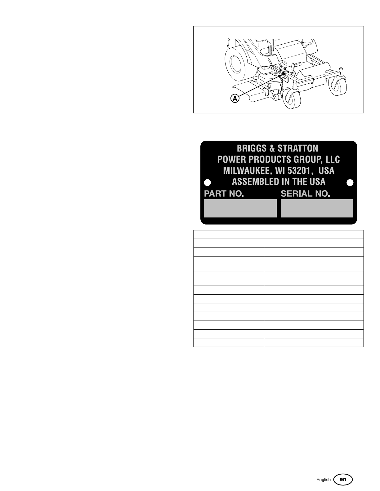
Identification Tag Location
The Product Identification tag (A, Figure 1) can be found in the
location shown.
PRODUCT REFERENCE DATA
Unit Model Number:
Unit Serial Number:
Mower Deck Model Number: (if
applicable)
Mower Deck Serial Number: (if
applicable)
Dealer Name:
Date Purchased:
ENGINE REFERENCE DATA
Engine Make:
Engine Model:
Engine Type/Spec:
Engine Code/Serial Number
When contacting your authorized service dealer for replacement
parts, service, or information you MUST have these numbers.
NOTE: For the location of the engine identification numbers,
refer to engine owner's manual.
The Illustrated Parts List for this machine can be downloaded
from ferrisindustries.com. Please provide model and serial
number when ordering replacement parts.
3
Page 4
Operator Safety
WARNING
U.S.A. Models: The engine exhaust from this product
contains chemicals known to the State of California to
cause cancer, birth defects, or other reproductive harm.
Read the Manual
WARNING
Battery posts, terminals, and related accessories contain
lead and lead compounds, chemicals known to the State
of California to cause cancer and birth defects or other
reproductive harm. Wash hands after handling.
Read these safety rules and follow them closely. Failure to obey
these rules could result in loss of control of unit, severe personal
injury or death to you, or bystanders, or damage to property or
equipment. This mowing deck is capable of amputating
hands and feet and throwing objects.
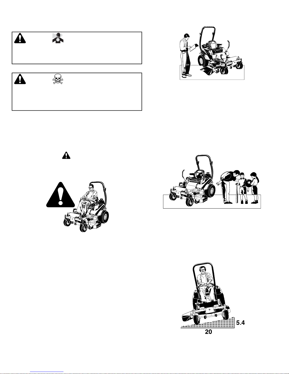
The safety alert triangle in text signifies important cautions
or warnings which must be followed.
Operating Safety
Congratulations on purchasing a superior-quality piece of lawn
and garden equipment. Our products are designed and
manufactured to meet or exceed all industry standards for safety.
Do not operate this machine unless you have been trained.
Reading and understanding this operator’s manual is a way to
train yourself.
The operator’s manual contains important safety information
you need to be aware of BEFORE you operate your unit as well
as DURING operation.
Safe operating techniques, an explanation of the product’s
features and controls, and maintenance information is included
to help you get the most out of your equipment investment.
Be sure to completely read the Safety Rules and Information
found on the following pages. Also completely read the
Operation section.
Children
Tragic accidents can occur with children. Do not allow them
anywhere near the area of operation. Children are often attracted
to the unit and mowing activity. Never assume that children will
remain where you last saw them. If there is a risk that children
may enter the area where you are mowing, have another
responsible adult watch them.
Slope Operation
Power equipment is only as safe as the operator. If it is misused,
or not properly maintained, it can be dangerous! Remember,
you are responsible for your safety and that of those around
you.
Use common sense, and think through what you are doing. If
you are not sure that the task you are about to perform can be
safely done with the equipment you have chosen, ask a
professional: contact your local authorized dealer.
Operation on slopes can be dangerous. Using the unit on a
slope that is too steep where you do not have adequate wheel
traction (and control) can cause sliding, loss of steering, control,
4 ferrisindustries.com
Page 5
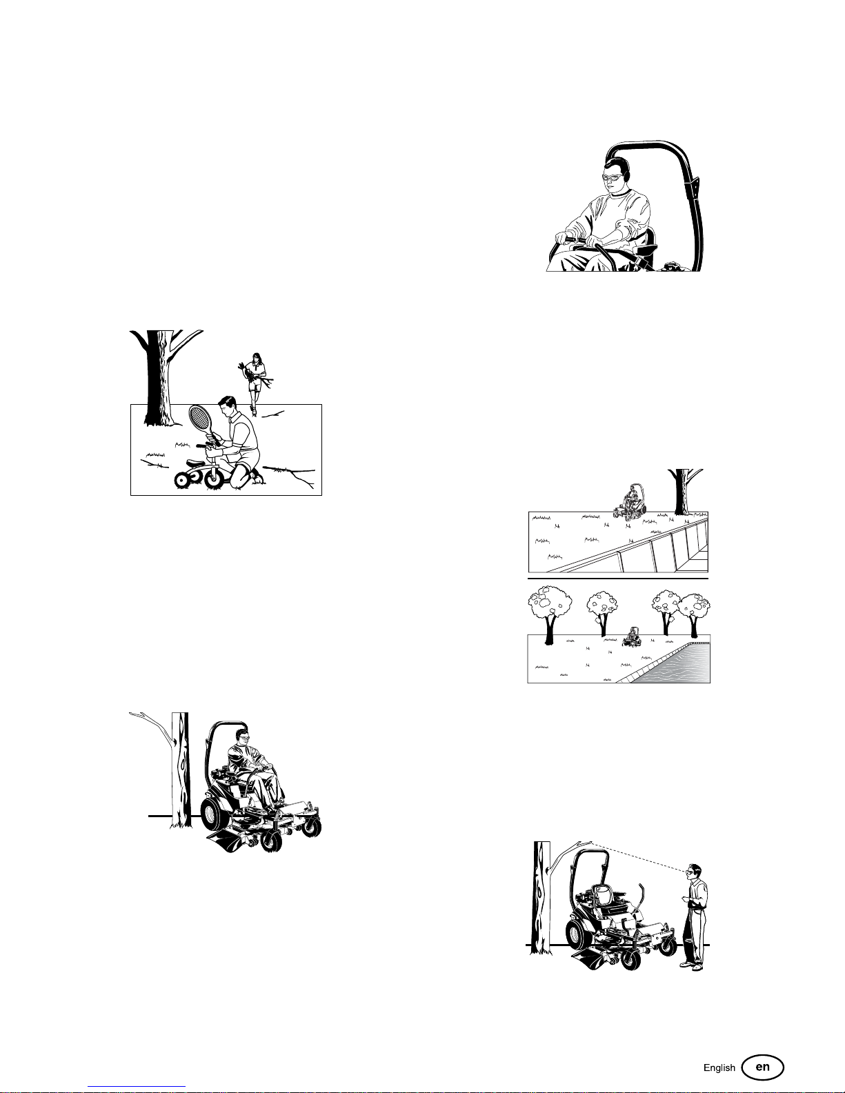
and possible rollover. You should not operate on a slope greater
than a 5.4 foot rise over a 20 foot length (15 degrees).
Always mow across slopes, not up and down (to maintain
traction on the wheels) and avoid sudden turns or rapid speed
changes. Reduce speed and use extreme caution on ALL
slopes.
Also, note that the surface condition you are on can greatly
impact your ability to safely operate this machine. Operating on
wet or slippery slopes can cause sliding and loss of steering
and control. Do not operate on slopes that are slippery, wet, or
have soft soil conditions.
If you feel unsure about operating the unit on a slope, don’t do
it. It’s not worth the risk.
Thrown Objects
attempt to alter or bypass the system. See your dealer
immediately if the system does not pass all the safety interlock
system tests found in this manual.
Roll Bar Use
Keep the roll bar in the raised position and fasten the seat belt.
There is no roll over protection when the roll bar is down! Do
not jump off if the mower tips (it is safer to be secured by the
seat belt with the roll bar raised.)
Lower the roll bar only when necessary (such as to temporarily
clear a low overhanging obstacle) and NEVER remove it. Do
NOT use the seat belt when the roll bar is down. Raise the roll
bar as soon as clearance permits.
Retaining Walls, Drop-Offs and Water
This unit has spinning mower blades. These blades can pick
up and throw debris that could seriously injure a bystander. Be
sure to clean up the area to be mowed and remove objects that
could be thrown by the blade BEFORE you start mowing.
Do not operate this unit without the entire grass catcher or
discharge guard (deflector) in place.
Also, do not allow anyone in the area while the unit is running!
If someone does enter the area, shut the unit off immediately
until they leave.
Moving Parts
This equipment has many moving parts that can injure you or
someone else. However, if you stay in the operator zone (stay
seated in the seat), and follow the safety rules in this operator’s
manual, the unit is safe to operate.
Retaining walls and drop-offs around steps and water are a
common hazard. Give yourself a minimum of two mower widths
of clearance around these hazards and hand-trim with a walk
behind mower or string trimmer. Wheels dropping over retaining
walls, edges, ditches, embankments, or into water can cause
rollovers, which may result in serious injury, death, or drowning.
Overhead Obstacles
The mower deck has spinning mower blades that can amputate
hands and feet. Do not allow anyone near the unit while it is
running! Keep safety devices (guards, shields, and switches)
in place and working.
To help you, the operator, use this equipment safely, it is
equipped with an operator-present safety system. Do NOT
Check for overhead clearances before driving under any objects.
Do not allow the roll bar to contact low overhanging obstacles
such as tree branches and guide wires.
5
Page 6
Fuel and Maintenance
Always disengage all drives, shutoff the engine, and remove
the key before doing any cleaning, refueling, or servicing.
Gasoline and its vapors are extremely flammable. Do not smoke
while operating or refueling. Do not add fuel while engine is hot
or running. Allow engine to cool for at least 3 minutes prior to
adding fuel.
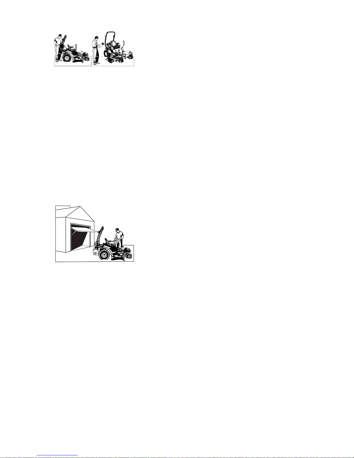
Do not add fuel indoors, in an enclosed trailer, garage, or any
other enclosed area that is not well ventilated. Gasoline spills
should be cleaned up promptly and before operation begins.
Gasoline should be stored only in sealed containers approved
for fuel.
Proper maintenance is critical to the safety and performance of
your unit. Keep the unit free of grass, leaves, and excess oil.
Be sure to perform the maintenance procedures listed in this
manual, especially periodically testing the safety system.
Enclosed Areas
• Data indicates that operators, age 60 years and above, are
involved in a large percentage of riding mower-related
injuries. These operators should evaluate their ability to
operate the riding mower safely enough to protect
themselves and others from serious injury.
Preparation
• Evaluate the terrain to determine what accessories and
attachments are needed to properly and safely perform the
job. Use only accessories and attachments approved by
the manufacturer.
• Wear appropriate clothing including safety shoes, safety
glasses and ear protection. Long hair, loose clothing or
jewelry may get tangled in moving parts.
• Inspect the area where the equipment is to be used and
remove all objects such as rocks, toys and wire, which can
be thrown by the machine.
• Use extra care when handling gasoline and other fuels.
They are flammable and vapors are explosive.
• Use only an approved container.
• Never remove fuel cap or add fuel with the engine running.
Allow engine to cool before refueling. Do not smoke.
• Never refuel or drain the machine indoors.
• Check that operator’s presence controls, safety switches
and shields are attached and functioning properly. Do not
operate unless they are functioning properly.
Only operate this unit outdoors and away from unventilated
areas such as inside garages or enclosed trailers. The engine
emits poisonous carbon monoxide gas and prolonged exposure
in an enclosed area can result in serious injury or death.
Training
• Read, understand, and follow all instructions in the manual
and on the unit before starting. If the operator(s) or
mechanic(s) can not read English it is the owner’s
responsibility to explain this material to them.
• Become familiar with the safe operation of the equipment,
operator controls, and safety signs.
• All operators and mechanics should be trained. The owner
is responsible for training the users.
• Only allow responsible adults, who are familiar with the
instructions, to operate the unit.
• Never let children or untrained people operate or service
the equipment. Local regulations may restrict the age of the
operator.
• The owner/user can prevent and is responsible for accidents
or injuries occurring to themselves, other people or property.
Operation
• Never run an engine in an enclosed area.
• Mow only in the daylight or with good artificial light, keeping
away from holes and hidden hazards.
• Be sure all drives are in neutral and parking brake is
engaged before starting engine. Only start engine from the
operator’s position. Use seat belts if provided.
• Be sure of your footing while using pedestrian controlled
equipment, especially when backing up. Walk, don’t run.
Reduced footing could cause slipping.
• Slow down and use extra care on hillsides. Be sure to travel
in the recommended direction on hillsides. Turf conditions
can affect the machines stability. Use caution when
operating near drop-offs.
• Do not mow in reverse unless absolutely necessary. Always
look down and behind before and while traveling in reverse.
• Be aware of the mower discharge direction and do not point
it at anyone. Do not operate the mower without either the
entire grass catcher or the deflector in place.
• Slow down and use caution when making turns and when
changing directions on slopes.
• Never raise deck with the blades running.
• Never leave a running unit unattended. Always disengage
the PTO, set parking brake, stop engine, and remove keys
before dismounting. Keep hands and feet away from the
cutting units.
6 ferrisindustries.com
Page 7
• Turn off the PTO switch to disengage the blades when not
mowing.
• Never operate with guards not securely in place. Be sure
all interlocks are attached, adjusted properly and functioning
properly.
• Never operate with the discharge deflector raised, removed
or altered, unless using a grass catcher.
• Do not change the engine governor setting or overspeed
the engine.
• Stop on level ground, lower implements, disengage drives,
engage parking brake, shut off engine before leaving the
operator’s position for any reason including emptying the
grass catchers or unclogging the chute.
• Stop equipment and inspect blades after striking objects or
abnormal vibration occurs. Make necessary repairs before
resuming operations.
• Keep hands and feet away from the cutting units.
• Look behind and down before backing up to be sure of a
clear path.
• Never carry passengers and keep pets and bystanders
away.
• Do not operate the unit while under the influence of alcohol
or drugs.
• Slow down and use caution when making turns and crossing
roads and sidewalks. Stop blades if not mowing.
• Use care when loading or unloading the machine into a
trailer or truck.
• Use care when approaching blind corners, shrubs, trees or
other objects that may obscure vision.
• To reduce fire hazard, keep unit free of grass, leaves &
excess oil. Do not stop or park over dry leaves, grass or
combustible materials.
WARNING
It is a violation of California Public Resource Code, Section
4442, to use or operate the engine on any forest-covered,
brush-covered or grass-covered land unless the exhaust
system is equipped with a spark arrester, as defined in Section
4442, maintained in effective working order. Other states or
federal jurisdictions may have similar laws. Contact an
Authorized Service Dealer to obtain a spark arrester designed
for the exhaust system installed on this engine.
• OSHA regulations may require the use of hearing protection
when exposed to sound levels greater than 85 dBA for an
8 hour time period.
CAUTION
This machine produces sound levels in excess of 85 dBA at
the operator’s ear and can cause hearing loss though
extended periods of exposure.
Wear hearing protection when operating this machine.
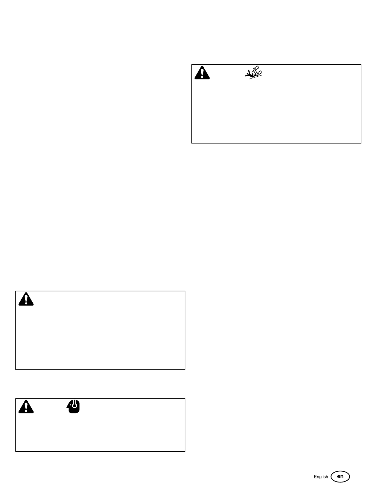
Slope Operation
Slopes are a major factor related to loss-of-control and tip-over
accidents, which can result in severe injury or death. All slopes
require extra caution. If you cannot back up the slope or if you
feel uneasy on it, do not drive on it.
WARNING
Do not use this machine on slopes greater than 15°.*
Select slow ground speed before driving onto slope. Use extra
caution when operating on slopes with rear-mounted grass
catchers.
Mow across the face of slopes, not up and down, use caution
when changing directions and DO NOT START OR STOP
ON SLOPE.
* This limit was determined per CEN Standard EN 836:1997, Section 5.2.2
and is based on the EN 836 Stability Test procedure described in Section
4.2.4.2. The 15 degree “limit of stability” is equal to 50% of the angle at
which machine lift-off occurred in static tests. Actual dynamic stability may
vary depending on operating conditions.
Do:
• Mow across slopes, not up and down.
• Remove obstacles such as rocks, tree limbs, etc.
• Watch for holes, ruts, or bumps. Uneven terrain could
overturn the unit. Tall grass can hide obstacles.
• Use slow speed. Choose a slow speed so that you will not
have to stop or change speed while on the slope.
• Use extra care with grass catchers or other attachments.
These can change the stability of the unit.
• Keep all movement on the slopes slow and gradual. Do not
make sudden changes in speed or direction.
• See your authorized dealer for recommendations of
available weights to improve stability.
Do NOT:
• Avoid starting, stopping, or turning on a slope. If tires lose
traction (i.e. machine stops forward motion on a slope),
disengage the blade(s) (PTO) and drive slow off the slope.
• Do not turn on slopes unless necessary, and then, turn
slowly and gradually uphill, if possible. Never mow down
slopes.
• Do not mow near drop-offs, ditches, or embankments. The
operator could lose footing or balance or mower could
suddenly turn over if a wheel is over the edge of a cliff or
ditch, or if an edge caves in.
• Do not mow on wet grass. Reduced footing or traction could
cause sliding.
• Do not try to stabilize the unit by putting your foot on the
ground. (ride-on units).
• Do not mow excessively steep slopes.
• Do not use grass catcher on steep slopes.
• Do not mow slopes if you cannot back up them.
7
Page 8

Towed Equipment (Ride-On Units)
• Tow only with a machine that has a hitch designed for
towing. Do not attach towed equipment except at the hitch
point.
• Follow the manufacturer’s recommendations for weight limit
for towed equipment and towing on slopes. See attaching
a trailer under OPERATION.
• Never allow children or others in or on towed equipment.
• On slopes, the weight of the towed equipment may cause
loss of traction and loss of control.
• Travel slowly and allow extra distance to stop.
• Do not shift to neutral and coast down hill.
Children
Tragic accidents can occur if the operator is not alert to the
presence of children. Children are often attracted to the unit
and the mowing activity. Never assume that children will remain
where you last saw them.
• Keep children out of the mowing area and under the
watchful care of another responsible adult.
• Be alert and turn unit off if children enter the area.
• Before and during reverse operation, look behind and down
for small children.
• Never carry children, even with the blade(s) off. They may
fall off and be seriously injured or interfere with safe unit
operation. Children who have been given rides in the past
may suddenly appear in the mowing area for another ride
and be run over or backed over by the machine.
• Never allow children to operate the unit.
• Use extra care when approaching blind corners, shrubs,
trees, or other objects that may obscure vision.
Emissions
• Engine exhaust from this product contains chemicals known,
in certain quantities, to cause cancer, birth defects, or other
reproductive harm.
• Look for the relevant Emissions Durability Period and Air
Index information on the engine emissions label.
Ignition Systems (Gasoline Models)
• This spark ignition system complies with Canadian
ICES-002.
Service and Maintenance
To avoid personal injury or property damage, use extreme care
in handling gasoline. Gasoline is extremely flammable and the
vapors are explosive.
Safe Handling of Gasoline
• Extinguish all cigarettes, cigars, pipes, and other sources
of ignition.
• Use only approved gasoline containers.
• Never remove the gas cap or add fuel with the engine
running. Allow the engine to cool before refueling.
• Never fuel the machine indoors.
• Never store the machine or fuel container where there is
an open flame, spark, or pilot light such as near a water
heater or other appliance.
• Never fill containers inside a vehicle or on a truck bed with
a plastic bed liner. Always place containers on the ground
away from your vehicle before filling.
• Remove gas-powered equipment from the truck or trailer
and refuel it on the ground. If this is not possible, then refuel
such equipment on a trailer with a portable container, rather
than from a gasoline dispenser nozzle.
• Keep nozzle in contact with the rim of the fuel tank or
container opening at all times until fueling is complete. Do
not use a nozzle lock-open device.
• If fuel is spilled on clothing, change clothing immediately.
• Never over-fill the fuel tank. Replace gas cap and tighten
securely.
• Use extra care in handling gasoline and other fuels. They
are flammable and vapors are explosive.
• If fuel is spilled, do not attempt to start the engine but move
the machine away from the area of spillage and avoid
creating any source of ignition until fuel vapors have
dissipated.
• Replace all fuel tank caps and fuel container caps securely.
Maintenance and Storage
• Always observe safe refueling and fuel handling practices
when refueling the unit after transportation or storage.
• Always follow the engine manual instructions for storage
preparations before storing the unit for both short and long
term periods.
• Always follow the engine manual instructions for proper
start-up procedures when returning the unit to service.
• Never store the machine or fuel container inside where
there is an open flame, such as in a water heater. Allow
unit to cool before storing.
• Shut off fuel while storing or transporting. Do not store fuel
near flames or drain indoors.
• Keep all hardware, especially blade attachment bolts, tight
and keep all parts in good working condition. Replace all
worn or damaged decals.
• Never tamper with safety devices. Check their proper
operation regularly.
• Disengage drives, lower implement, set parking brake, stop
engine and remove key or disconnect spark plug wire. Wait
for all movement to stop before adjusting, cleaning or
repairing.
• Clean grass and debris from cutting units, drives, mufflers,
and engine to prevent fires. Clean up oil or fuel spillage.
• Let engine cool before storing and do not store near flame.
8 ferrisindustries.com
Page 9
• Stop and inspect the equipment if you strike an object.
Repair, if necessary, before restarting.
• Park machine on level ground. Never allow untrained
personnel to service machine.
• Use jack stands to support components when required.
• Carefully release pressure from components with stored
energy.
• Disconnect battery or remove spark plug wire before making
any repairs. Disconnect the negative terminal first and the
positive last. Reconnect positive first and negative last.
• Use care when checking blades. Wrap the blade(s) or wear
gloves, and use caution when servicing them. Only replace
blades. Never straighten or weld them.
• Keep hands and feet away from moving parts. If possible,
do not make adjustments with the engine running.
• Charge batteries in an open well ventilated area, away from
spark and flames. Unplug charger before connecting or
disconnecting from battery. Wear protective clothes and
use insulated tools.
• Grass catcher components are subject to wear, damage,
and deterioration, which could expose moving parts or allow
objects to be thrown. Frequently check components and
replace with manufacturer’s recommended parts, when
necessary.
• Check brake operation frequently. Adjust and service as
required.
• Use only factory authorized replacement parts when making
repairs.
• Always comply with factory specifications on all settings
and adjustments.
• Only authorized service locations should be utilized for
major service and repair requirements.
• Never attempt to make major repairs on this unit unless you
have been properly trained. Improper service procedures
can result in hazardous operation, equipment damage and
voiding of manufacturer’s warranty.
• Units with hydraulic pumps, hoses, or motors: WARNING:
Hydraulic fluid escaping under pressure may have sufficient
force to penetrate skin and cause serious injury. If foreign
fluid is injected into the skin it must be surgically removed
within a few hours by a doctor familiar with this form of injury
or gangrene may result. Keep body and hands away from
pin holes or nozzles that eject hydraulic fluid under high
pressure. Use paper or cardboard, and not hands, to search
for leaks. Make sure all hydraulic fluid connections are tight
and all hydraulic hoses and lines are in good condition
before applying pressure to the system. If leaks occur, have
the unit serviced immediately by your authorized dealer.
• WARNING: Stored energy device. Improper release of
springs can result in serious personal injury. Springs should
be removed by an authorized technician.
• Models equipped with an engine radiator: WARNING: Stored
energy device. To prevent serious bodily injury from hot
coolant or steam blow-out, never attempt to remove the
radiator cap while the engine is running. Stop the engine
and wait until it is cool. Even then, use extreme care when
removing the cap.
Roll Bar Instructions
For models equipped with factory-installed Roll Over Protection
System (ROPS).
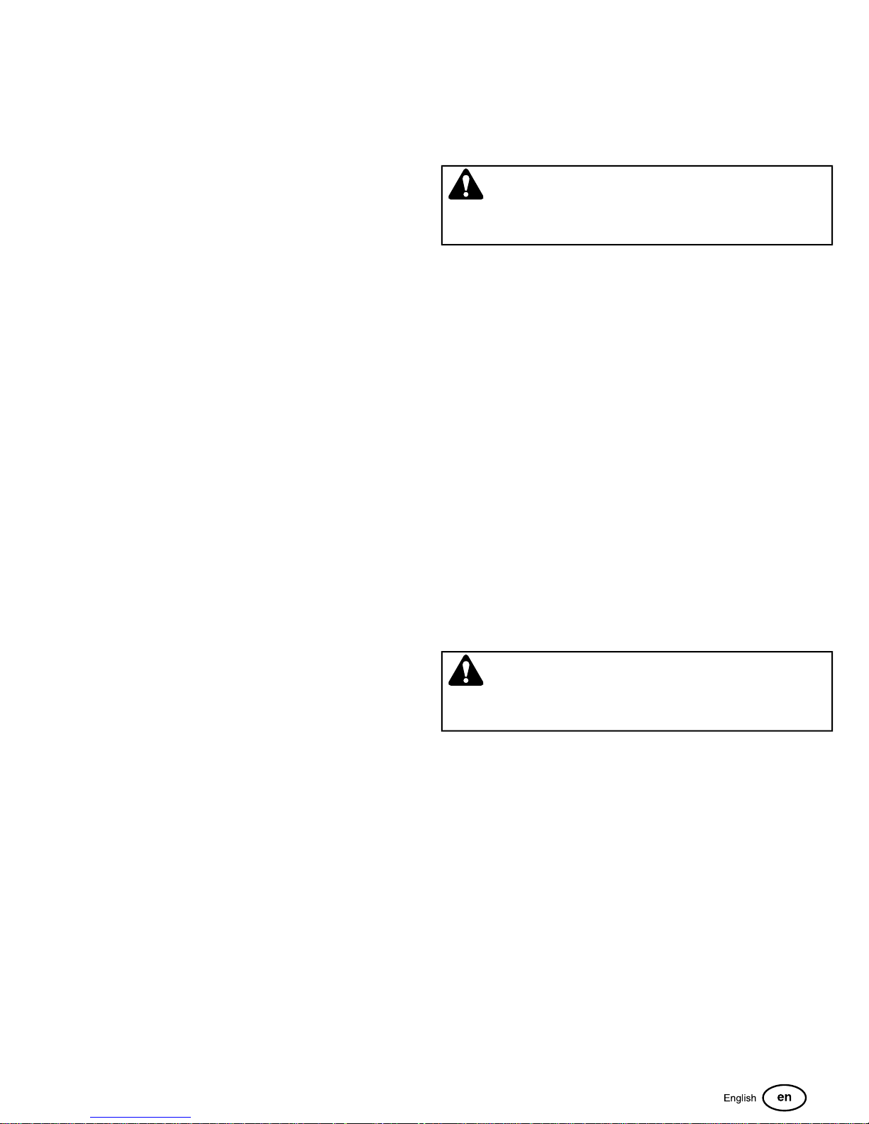
WARNING
In order to avoid serious injury or death from roll over, it is
important to follow the warnings listed below.
Operational Warnings
• Always use the seat belt when the roll bar is in the raised
position.
• Never use the seat belt when the roll bar is in the down
position.
• Remember there is no roll over protection when the roll bar
is in the down position so it is very important to always keep
the roll bar in the raised position whenever possible.
• Lower the roll bar to the down position only when it is
absolutely necessary.
• Check for overhead clearances before driving under any
objects. Do not allow roll bar to contact low overhanging
obstacles such as tree branches and guide wires.
• Never remove the roll bar from the vehicle.
• Do not exceed the machine weight rating of the roll bar.
• Read and follow all of the instructions shown below
regarding the inspection and maintenance of the roll bar
structure and the seat belt.
Inspection of the Roll Bar Protective Structure
WARNING
Failure to properly inspect and maintain the ROLL BAR
protective structure can cause serious injury or death.
A ROLL BAR, like any other safety device, needs to be
periodically inspected to verify that the integrity of the device
has not been compromised through normal machine use,
misuse, age degradation, modifications, or a roll over.
To maintain operator roll over protection and roll bar
effectiveness:
• If a ROLL BAR becomes damaged for any reason, such as
a collision, roll over or impact, the ROLL BAR must be
replaced. Small undetectable cracks can reduce the
effectiveness of the ROLL BAR. Never weld, straighten, or
repair the ROLL BAR.
• Never alter the ROLL BAR by welding anything to it or by
drilling additional holes.
• BEFORE FIRST TIME USE - Inspect the ROLL BAR
structure and mounting hardware for:
1) Check to make sure the machine GVW (Gross Vehicle
Weight), including attachments, restrained payload, fuel
9
Page 10
and operator, is not in excess of the maximum weight
specified on the ROLL BAR label.
2) Make sure there isn’t any missing, damaged, or loose
mounting hardware.
3) Make sure the ROLL BAR has been correctly and
completely installed.
• EVERY 100 HOURS - Inspect the ROLL BAR structure and
mounting hardware for:
1) Any cracks in the structure (structural members and/or
welds).
2) Significant corrosion on any part of the ROLL BAR
structure or hardware.
3) Missing, damaged, or loose mounting hardware
4) Mounting hardware that is of a grade lesser than
specified.
compromised through normal machine use, misuse, age
degradation, modifications, or a roll over. If the seat belt
does not pass all of the following tests, it should be replaced.
• BEFORE EACH USE – Conduct the following
inspections/maintenance of the seat belt and retraction
mechanism:
1) Check for dirt or debris in the retraction mechanism. If
dirt or debris is found, it should be removed.
2) Check to make sure the retraction mechanism retracts
easily and completely.
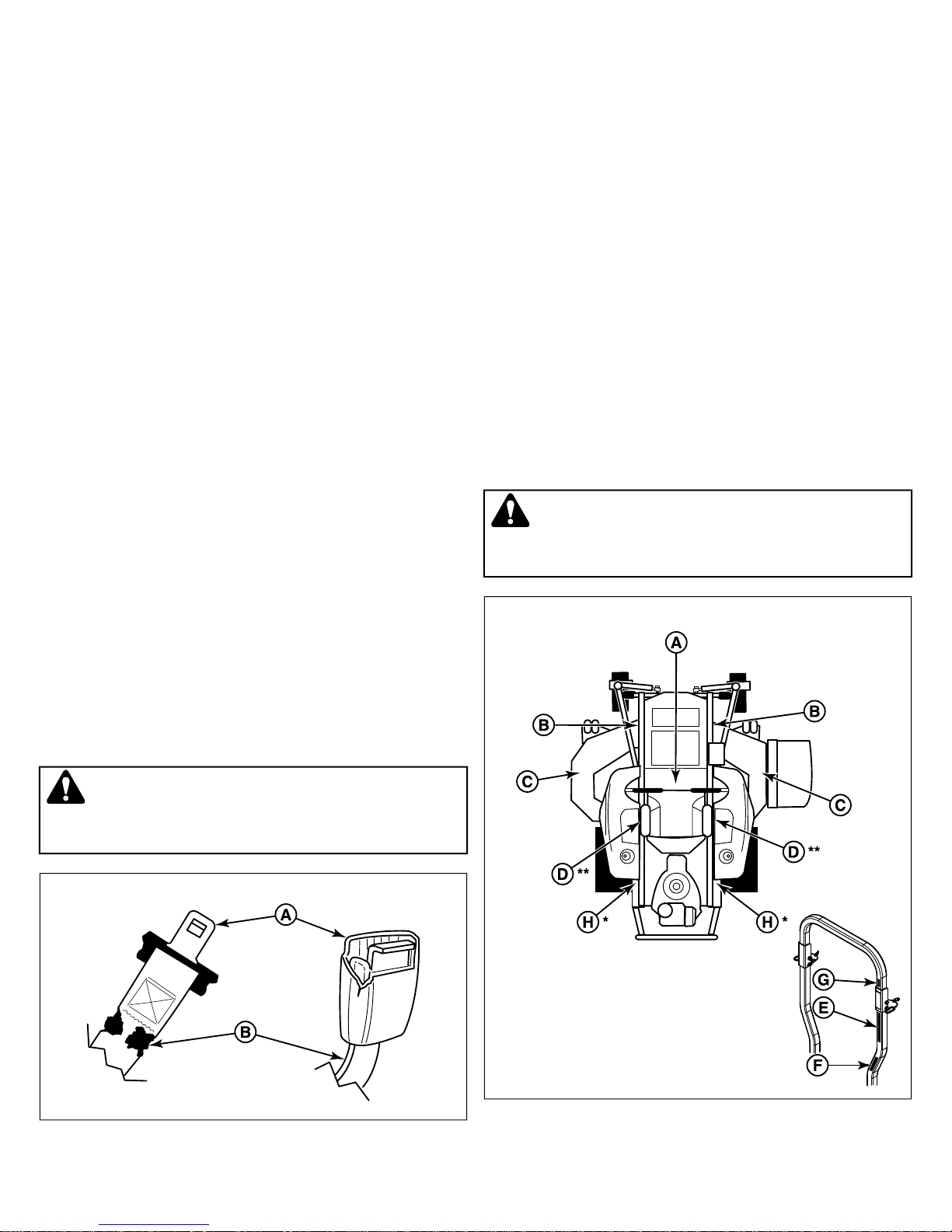
3) Check for damage to any part of the seat belt (A, Figure
2) such as nicks, cuts, loose stitching, or fraying.
4) Check that the buckle and latch (B) operate properly and
that the latch plate is not excessively worn, deformed, or
the buckle is damaged or cracked. The seat belt should
latch and release easily.
5) Machine GVW (Gross Vehicle Weight), including
attachments, restrained payload, fuel and operator, in
excess of the maximum weight specified on the ROLL BAR
label.
6) Any modifications that have been made, such as
unauthorized welds and holes.
7) Any permanent deformation or twisting of the ROLL BAR
structure.
8) That the ROLL BAR label is still in place and is readable.
9) That the ROLL BAR on-product warning labels are still
on the ROLL BAR and are readable.
• If there is any doubt as to the condition of the ROLL BAR,
remove the machine from service and contact your dealer
for assistance.
Inspection and Maintenance of the Roll Bar Seat
Belt
WARNING
Failure to properly inspect and maintain the seat belt can
cause serious injury or death.
Safety Decals
Before operating your unit, read the safety decals. The cautions
and warnings are for your safety. To avoid a personal injury or
damage to the unit, understand and follow all safety decals.
WARNING
If any safety decals become worn or damaged, and cannot
be read, order replacement decals from your local dealer.
3
2
* Located behind ROPS on the frame of the unit.
• The seat belt like the ROLL BAR, needs to be periodically
inspected to verify that the integrity has not been
10 ferrisindustries.com
** Located near the transmission fans.
Page 11
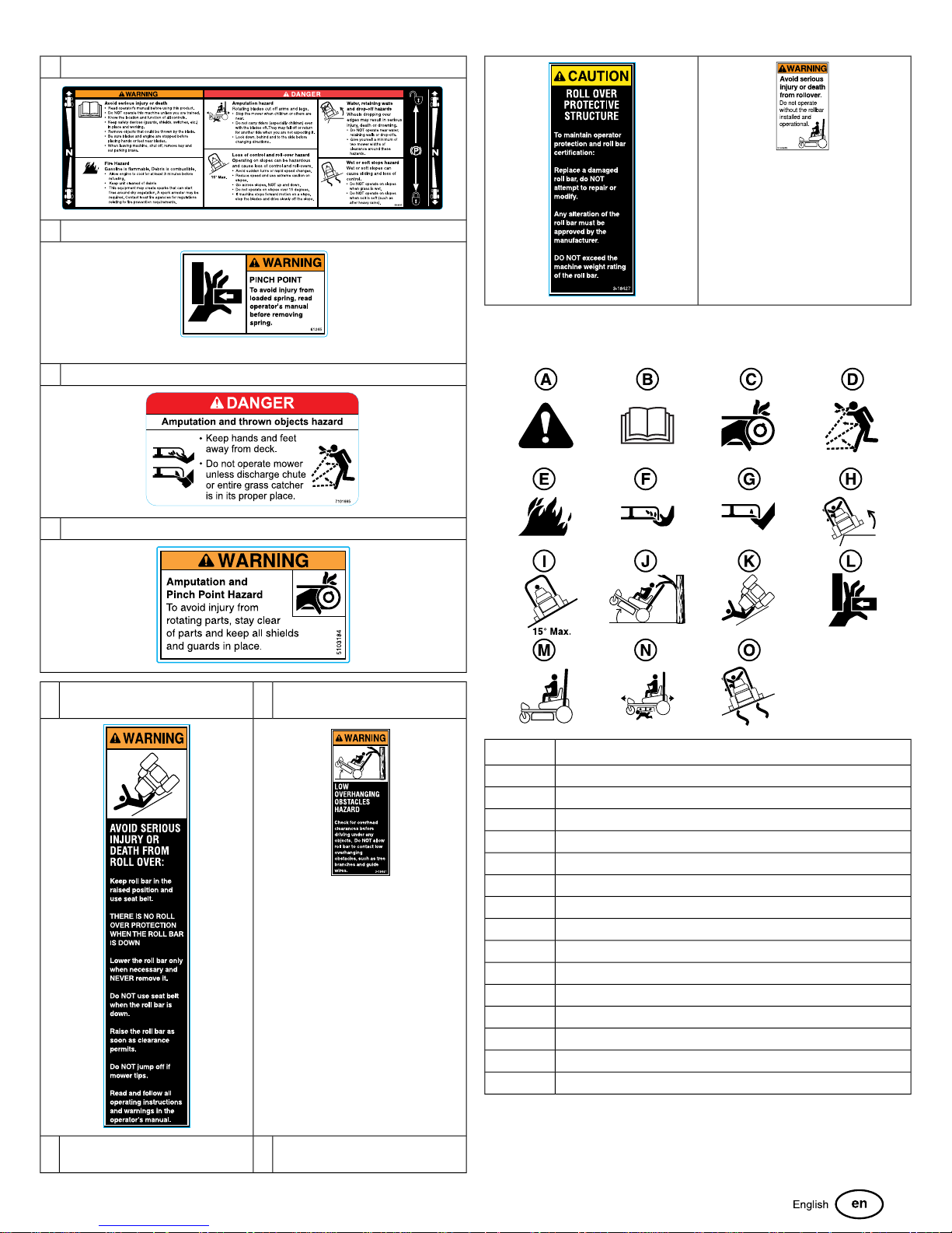
Part No.: 5103595 - Decal, Main SafetyA
Part No.: 5061245 - Decal, Pinch PointB
Qty: 2 - Models w/ 61" Decks; Qty: 1 - Models w/ 52" Decks
Part No.: 7101665 - Decal, DangerC
Part No.: 5103184 - Decal, WarningD
Part No.: 5100405 - Decal,
E
Warning, FLDG RL BR
GPart No.: 51004082 - Decal,
Warning, ROPS
Safety Icons
DescriptionCallout
AlertA
Read the ManualB
Amputation - Rotating PartsC
Thrown ObjectsD
Fire HazardE
Amputation - Hand in BladeF
Amputation - Foot in BladeG
DropoffsH
Maximum Slope Angle for Safe OperationI
Overhead ObstaclesJ
Rollover HazardK
Pinch PointL
Keep ROPS in Raised PositionM
Keep Children AwayN
Slippery SlopesO
Part No.: 5100683 - Decal,
F
Caution, FLDG RL BR
HPart No.: 5104083 - Decal,
Warning, ROPS Removed
11
Page 12
Safety Alert Symbol and Signal Words
The safety alert symbol indicates a potential personal injury
hazard. A signal word (DANGER, WARNING, or CAUTION) is
used with the alert symbol to designate a degree or level of
hazard seriousness. A safety symbol may be used to represent
the type of hazard. The signal word NOTICE is used to address
practices not related to personal injury.
WARNING
If the unit does not pass a safety test, do not operate it. See
your authorized dealer. Under no circumstance should you
attempt to defeat the purpose of safety interlock system.
Features and Controls
DANGER indicates a hazard which, if not avoided,
will
result
in death or serious injury.
WARNING indicates a hazard which, if not avoided,
could
result in death or serious injury.
CAUTION indicates a hazard which, if not avoided,
could
result in minor or moderate injury.
NOTICE
indicates an action that could result in damage to the
product.
Safety Interlock System
This unit is equipped with safety interlock switches. These safety
systems are present for your safety, do not attempt to bypass
safety switches, and never tamper with safety devices. Check
their operation regularly.
Operational SAFETY Checks
Test 1 - Engine SHOULD NOT crank if:
• PTO switch is engaged, OR
• Parking brake is not engaged, OR
• Ground speed control levers are not in the NEUTRAL
position.
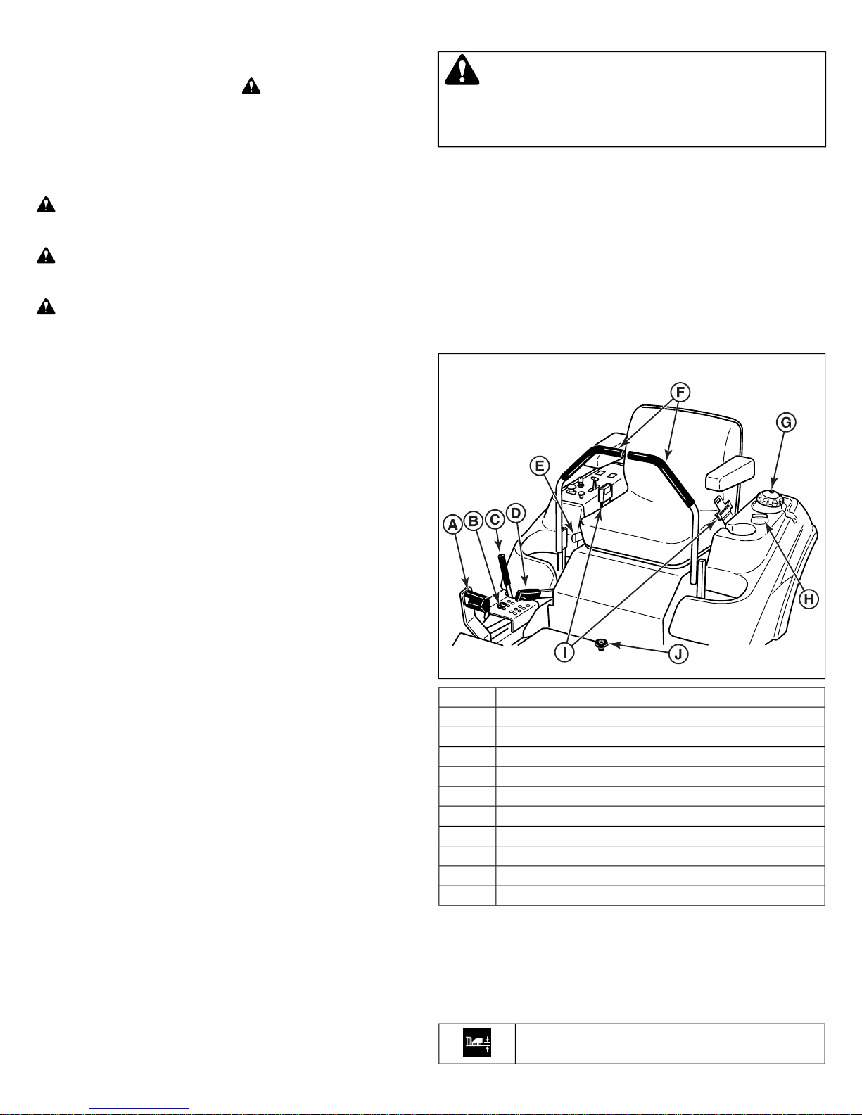
Control Functions and Locations
The information below briefly describes the function of individual
controls. Starting, stopping, driving, and mowing require the
combined use of several controls applied in specific sequences.
To learn what combination and sequence of controls to use for
various tasks see the
Tractor Controls
4
Operation
section.
Test 2 - Engine SHOULD crank if:
• PTO switch is not engaged, AND
• Parking brake is engaged, AND
• Ground speed control levers are locked in the NEUTRAL
position.
Test 3 - Engine should SHUT OFF if:
• Operator rises off seat with PTO engaged, OR
• Operator rises off seat with parking brake disengaged.
• Operator moves ground speed control levers out of their
neutral positions before disengaging parking brake.
Test 4 - Blade Brake Check
Mower blades and mower drive belt should come to a complete
stop within seven (7) seconds after electric PTO switch is turned
off (or operator rises off seat). If mower drive belt does not stop
within seven (7) seconds, see your dealer.
NOTE: Once the engine has stopped, PTO switch must be
turned off, parking brake must be engaged, and the ground
speed control levers must be locked in the NEUTRAL position
after the operator returns to the seat in order to start the engine.
Control NameCallout
Deck Lift PedalA
Cutting Height Adjustment PinB
Deck Lift Lock LeverC
Parking BrakeD
Seat Adjustment LeverE
Ground Speed Control LeversF
Fuel Tank CapG
Fuel Level GuageH
Retractable Seat BeltI
Removable Floor PlateJ
Deck Lift Pedal, Cutting Height Adjustment Pin & Deck Lift
Lock Lever: These control the cutting height of the mower deck.
Depress the pedal until it locks into the 5” (12.7 cm) position.
Place the adjustment pin in the desired cutting height and
release the lift lock lever.
Cutting Height Adjustment Pin
12 ferrisindustries.com
Page 13
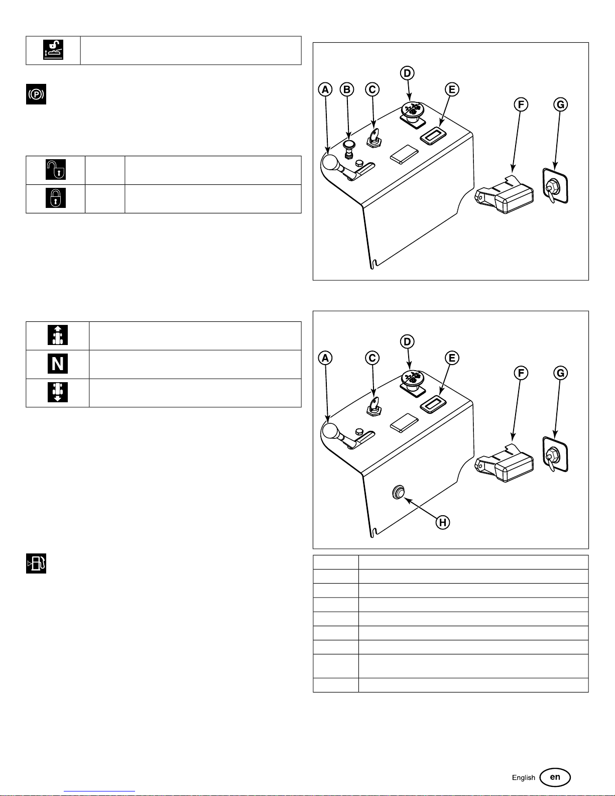
Deck Lift Lock Lever
Parking Brake: Pull the parking brake lever back to
engage the parking brake. Move the lever fully forward to
disengage the parking brake.
NOTE: To start the unit the parking brake must be engaged.
Releases the parking brake.Disengage
Locks the parking brake.Engage
Seat Adjustment Lever: The seat can be adjusted forward and
back. Move the lever towards the left, position the seat as
desired, and release the lever to lock the seat in position.
5
Ground Speed Control Levers: These levers control the
ground speed of the rider. The left lever controls the left rear
drive wheel and the right lever controls the right rear drive wheel.
FORWARD
NEUTRAL
REVERSE
Moving a lever forward increases the FORWARD speed of the
associated wheel, and pulling back on a lever increases the
REVERSE speed.
Note: The further a lever is moved away from the neutral position
the faster the drive wheel will turn.
See the
Zero-Turn Driving Practice
section for steering
instructions.
Fuel Tank Cap: To remove the cap, turn counter-clockwise.
Fuel Level Gauge: Displays the fuel level in the tank.
Retractable Seat Belt: The seat belt is used to secure the
operator to the seat.
The seat belt should always be worn when the Roll Bar is in
the raised position. The seat belt should never be worn when
the Roll Bar is in the down position.
Removable Floor Plate: The floor plate can be removed for
easy access to the mower deck. To remove the plate, remove
the retainer hardware and tilt the floor pan up and then remove
from the machine. Reverse the process for re-installation.
Instrument Control Panel
Carbureted Models:
Fuel Injected Models:
6
Control NameCallout
Throttle ControlA
ChokeB
Ignition SwitchC
PTO SwitchD
Hour MeterE
Fuse BlockF
G
Throttle Control: The throttle controls engine speed. Move the
throttle forward to increase engine speed and back to decrease
engine speed. Always operate at FULL throttle when mowing.
Fuel Selector Valve (Located on the left side of the machine on
the EVAP canister bracket)
Malfunction Indicator Lamp (M.I.L.)H
13
Page 14
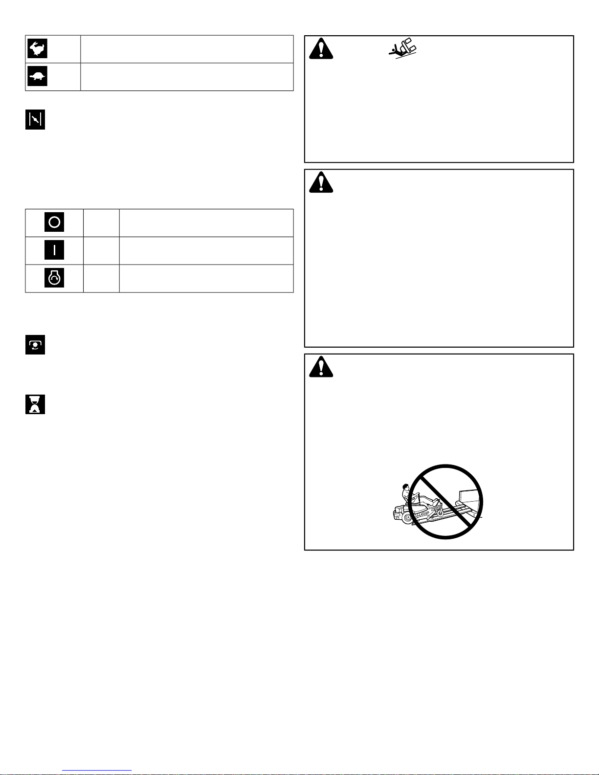
Fast throttle speed.
Slow throttle speed.
Choke: Close the choke for cold starting. Open the choke
once the engine starts. A warm engine may not require choking.
Pull the knob UP to close the choke. Push the knob DOWN to
open the choke.
WARNING
• Never operate on slopes greater than 15°.
• Select slow ground speed before driving onto a slope.
Use extra caution when operating on slopes with a
rear-mounted grass catcher.
• Mow across the face of slopes, not up and down, use
caution when changing direction on slopes and do NOT
start or stop on a slope.
Ignition Switch: The ignition switch starts and stops the engine,
it has three positions:
OFF
RUN
Stops the engine and shuts off the electrical
system.
Allows the engine to run and powers the electrical
system.
Cranks the engine for starting.START
NOTE: Never leave the ignition switch in the RUN position with
the engine stopped—this drains the battery.
PTO (Power Take Off) Switch: The PTO switch engages
and disengages the mower blades. Pull UP on the switch to
engage, and push DOWN to disengage.
Hour Meter: The hour meter measures the number of
hours the PTO has been engaged. The hour meter has a self
contained power source so the total hours are always visible.
Fuse Block: The fuse block houses fuses for the electrical
system.
WARNING
• Never allow passengers to ride on the unit.
• Before leaving the operator’s position for any reason,
engage the parking brake, disengage the PTO, stop the
engine and remove the key.
• To reduce fire hazard, keep the engine, rider and mower
free of grass, leaves and excess grease. Do NOT stop or
park rider over dry leaves, grass or combustible materials.
• Fuel is highly flammable and must be handled with care.
Never fill the tank when the engine is still hot from recent
operation. Do NOT allow open flame, smoking or matches
in the area. Avoid over-filling and wipe up any spills.
WARNING
Do NOT load this zero-turn rider on a trailer or truck using two
separate ramps. Only use a single ramp that is at least one
foot wider than the width of the rear wheels of this rider. This
rider has a zero turning radius and the rear wheels could fall
off the ramps, or the rider could tip over injuring the operator
or bystanders.
Malfunction Indicator Lamp (M.I.L.): The malfunction indicator
lamp detects problems with the engine. If the malfunction
indicator lamp begins to flash while you are operating the unit,
see the engine operator's manual.
Operation
Before First Time Operation
• Be sure to read all information in the Safety and Operation
sections before attempting to operate this tractor and
mower.
• Become familiar with all of the controls and how to stop the
unit.
• Drive in an open area without mowing to become
accustomed to the unit.
14 ferrisindustries.com
Checks Before Starting
• Check that the crankcase is filled to the full mark on the
crankcase oil fill and dipstick. If necessary, add oil through
the engine oil fill. See the engine Operator’s manual for
instructions, engine oil dipstick location and oil
recommendations.
• Make sure all nuts, bolts, screws and pins are in place and
tight.
• Adjust the seat position, and make certain you can reach
all the controls from operator’s position.
• Fill the fuel tank with fresh fuel. Refer to engine manual for
fuel recommendations.
Page 15
• Check the hydraulic oil level.
• Make sure that the fuel selector valve in an "ON" position.
Starting the Engine - Carbureted Models
WARNING
• If you do not understand how a specific control functions,
or have not yet thoroughly read the
section, do so now.
• Do NOT attempt to operate the tractor without first
becoming familiar with the location and function of all
controls.
Features & Controls
3. Insert the key into the ignition switch and turn it to START
position. Release switch as soon as engine starts. If starter
does not turn engine over, shut off key switch immediately,
and consult engine operator's manual.
Warm up the engine
by running it for at least a minute before engaging the PTO
switch or driving the rider.
4. After warming the engine always operate the unit at FULL
throttle when mowing.
In the event of an emergency the engine can be stopped
by simply turning the ignition switch to STOP.
method only in emergency situations. For normal engine shut
down follow the procedure given in
Stopping the Rider
Use this
.
Stopping the Rider
1. While sitting in the operator's seat, engage the parking brake
and make sure the PTO switch is disengaged and the
ground speed control levers are locked in the neutral
position.
2. A warm engine may not require choking. Set the engine
throttle control to FAST throttle position. Then fully close
the choke by pulling the knob OUT fully.
3. Insert the key into the ignition switch and turn it to START.
4. After the engine starts, gradually open the choke (push
knob down fully). Reduce to half throttle speed and allow
engine to warm.
Warm up the engine by running it for atleast
a minute before engaging the PTO switch or driving the
rider.
5. After warming the engine always operate the unit at FULL
throttle when mowing.
In the event of an emergency the engine can be stopped
by simply turning the ignition switch to STOP.
method only in emergency situations. For normal engine shut
down follow the procedure given in
Stopping the Rider
Use this
.
Starting the Engine - Fuel Injected Models
WARNING
• If you do not understand how a specific control functions,
or have not yet thoroughly read the
section, do so now.
• Do NOT attempt to operate the unit without first becoming
familiar with the location and function of all controls.
Features & Controls
1. Returning the ground speed control levers to the middle
position will stop rider movement. Pivot the levers outward
and lock them in NEUTRAL.
2. Disengage the PTO by pushing down on the PTO switch.
3. Engage the parking brake by pulling the handle up until it
locks into position.
4. Move the throttle control to mid-throttle position and turn
the ignition key to OFF. Remove the key.
Zero-Turn Driving Practice
The lever controls of the Zero Turn rider are responsive, and
learning to gain a smooth and efficient control of the rider’s
forward, reverse, and turning movements will take some
practice.
Spending some time going through the maneuvers shown and
becoming familiar with how the unit accelerates, travels, and
steers — before you begin mowing —is absolutely essential to
getting the most out of the Zero Turn rider.
Locate a smooth, flat area of your lawn — one with plenty of
room to maneuver. (Clear the area of objects, people and
animals before you begin.) Operate the unit at mid-throttle during
this practice session (ALWAYS operate at full throttle when
mowing), and turn slowly to prevent tire slippage and damage
to your lawn.
We suggest you begin with the Smooth Travel procedure to the
right, and then advance through the forward, reverse, and
turning maneuvers.
You must release the parking brake prior to moving the control
levers inward.
NOTE: To prime a dry fuel system, turn key switch to ON
position for one minute. Allow fuel pump to cycle and prime
system. Turn key switch OFF.
1. While sitting in the operator's seat, engage the parking brake
and make sure the PTO switch is disengaged and the
ground speed control levers are locked in the neutral
position.
2. Position the throttle control midway between SLOW and
FAST positions.
Smooth Travel
The lever controls of the Zero Turn rider are responsive.
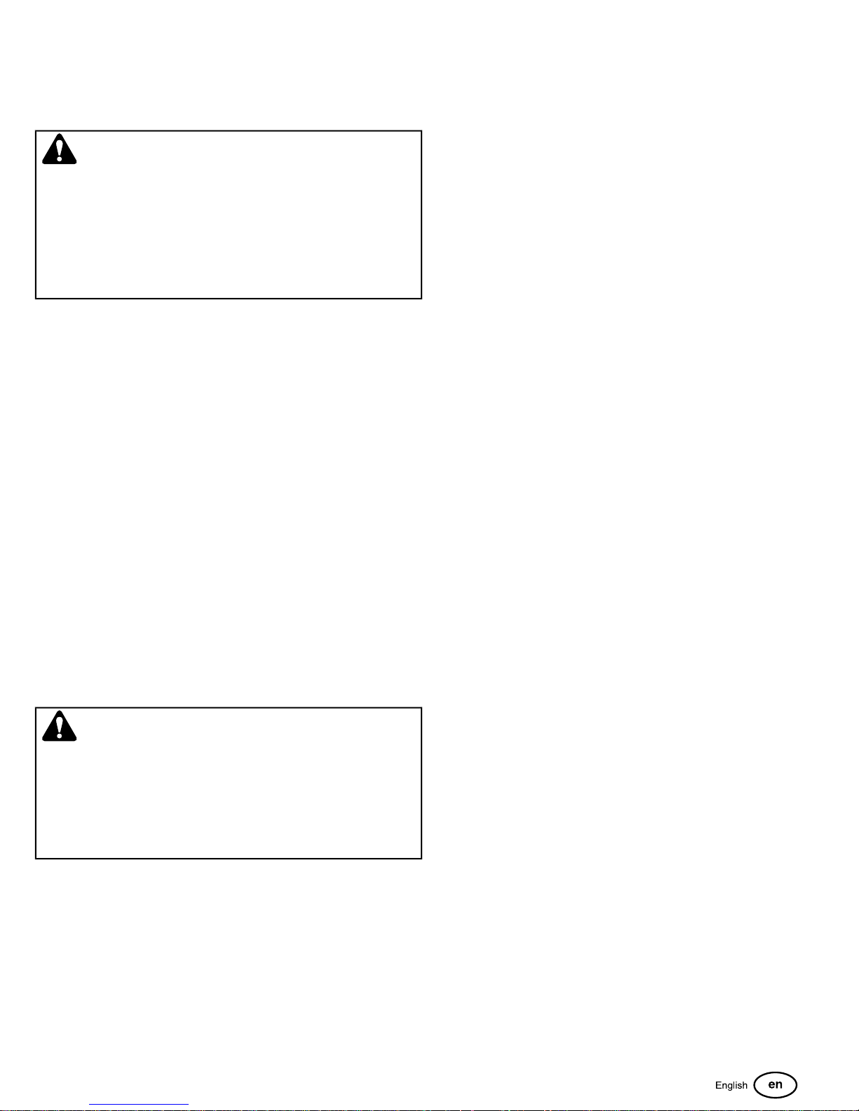
The BEST method of handling the ground speed control levers
is in three steps — as shown in Figure 7.
15
Page 16
7
FIRST place your hands onto the levers as shown.
SECOND, to go forward gradually push the levers forward with
your palms.
THIRD, to speed up move the levers farther forward. To slow
down smoothly, slowly move the levers toward neutral.
Reverse Travel Practice
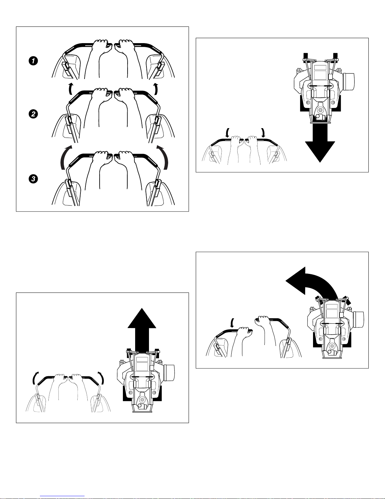
9
LOOK DOWN & BEHIND, then gradually move both ground
speed control levers evenly BACK from neutral. Slow down and
repeat.
NOTE: Practice backing up for several minutes before
attempting to do so near objects. The rider turns sharply in
reverse as well as forward, and backing up straight takes
practice.
Practice Turning Around A Corner
10
Basic Driving
Forward Travel Practice
8
Gradually move both ground speed control levers — evenly
FORWARD from neutral. Slow down and repeat.
NOTE: Straight forward travel takes practice. If necessary, top
speed can be balance-adjusted — see the Speed Balancing
Adjustment in the Adjustments section near the back of this
manual.
While traveling forward allow one handle to gradually return
back toward neutral. Repeat several times.
NOTE: To prevent pivoting directly on the tire tread, it is best
to keep both wheels going at least slightly forward.
Practice Turning in Place
16 ferrisindustries.com
Page 17
11
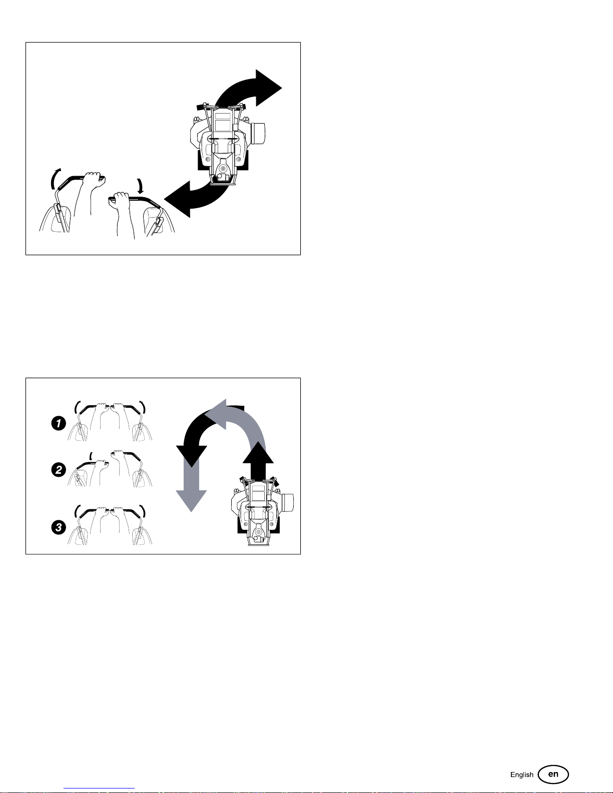
To turn in place, “Zero Turn,” gradually move one ground speed
control lever forward from neutral and one lever back from
neutral simultaneously. Repeat several times.
NOTE: Changing the amount each lever is pulled—forward or
back, changes the “pivot point” you turn on.
Advanced Driving
Executing an End-Of-Row Zero Turn
12
As you become more familiar and experienced with operating
the Zero Turn rider, you will learn more maneuvers that will
make your mowing time easier and more enjoyable.
Remember, the more you practice, the better your control
of the Zero Turn will be!
Mowing
1. Engage the parking brake. Make sure that the PTO switch
is disengaged, the ground speed control levers are locked
in the NEUTRAL position and the operator is in the seat.
2. Start the engine. See
3. Set the mower cutting height.
4. Set the throttle to the 1/2 throttle position.
NOTE: It is best practice to engage the PTO with the throttle
set at the minimum throttle position necessary to engage the
deck drive system without stalling the engine.
5. Engage the PTO by pulling up on the PTO switch.
6. Move the throttle to the "FAST" position and begin mowing.
7. When finished, reduce throttle speed so that the engine
idles and push the PTO switch down to shut off the PTO.
8. Stop the engine. See
Starting the Engine
Stopping the Rider
.
.
Mowing Recommendations
Several factors can affect how well your machine cuts grass,
Following proper mowing recommendations can improve the
performance and life of your machine.
Your Zero Turn Rider’s unique ability to turn in place allows you
to turn around at the end of a cutting row rather than having to
stop and Y-turn before starting a new row.
For example, to execute a left end-of row zero turn:
1. Slow down at the end of the row.
2. Move the RIGHT ground speed control lever forward slightly
while moving the LEFT ground speed control lever back to
center and then slightly back from center.
3. Begin mowing forward again.
This technique turns the rider LEFT and slightly overlaps the
row just cut —eliminating the need to back up and re-cut missed
grass.
Height of Grass
Often cutting height is a matter of personal preference. Typically,
you should mow the grass when it is between three and five
inches high. The proper cutting height range for a specific lawn
will depend upon several factors, including the type of grass,
the amount of rainfall, the prevailing temperature, and the lawn’s
overall condition.
Cutting the grass too short causes weak, thin grass plants,
which are easily damaged by dry periods and pests. Cutting
too short is often more damaging than allowing the grass to be
slightly higher.
Letting grass grow a bit longer—especially when it is hot and
dry—reduces heat build-up, preserves needed moisture and
protects the grass from heat damage and other problems.
However, allowing grass to grow too high can cause thin turf
and additional problems.
Cutting off too much at one time shocks the plant’s growth
system and weakens the grass plants. A good rule of thumb
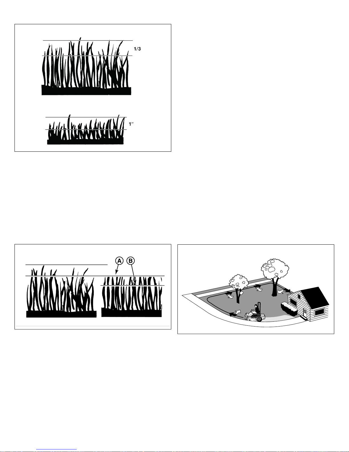
is the 1/3 rule: to cut no more than one third of the grass
height, and never more than 1 inch at a time.
17
Page 18
13
The amount of grass you are able to cut in one pass is also
effected by the type of mowing system you are using (for
example, broadcasting with side discharge decks can process
a much larger volume of grass than mulching does).
Tall grass requires incremental cutting. For extremely tall
grass, set the cutting height at maximum for the first pass (A,
Figure 14), and then reset it to the desired height and mow a
second (B) or third time.
Don’t cover the grass surface with a heavy layer of clippings.
Consider using a grass collection system and starting a compost
pile.
• Mow at time of day when the grass is cool and dry. Late
afternoon or early evening often provide these ideal mowing
conditions.
• Avoid mowing after rain or even heavy dew, and never
mulch when the grass is wet (moist grass does not mulch
well, and clumps beneath the mower deck).
Mowing Patterns
Always start mowing on a smooth, level area.
The size and type of area to be mowed will determine the best
mowing pattern to use. Obstructions such as trees, fences and
buildings, and conditions such as slopes and grades must also
be considered.
• Cut long straight strips overlapping slightly.
• Where possible, change patterns occasionally to eliminate
matting, graining or a corrugated appearance.
• For a truly professional cut, mow across the lawn in one
direction, then re-cut the lawn by mowing perpendicular to
the previous cut.
NOTE: Always operate the engine at FULL THROTTLE when
mowing.
If you hear the engine slowing down, you are mowing too
fast—using a slower ground speed will improve the cutting
efficiency of the blades and prevents many common cutting
problems. Use an appropriate ground speed for the thickness
and height of the grass you are cutting (3rd gear or slower for
manual gear models). If you hear the engine slowing down you
are mowing too fast, use a slower ground speed.
14
When and How Often to Mow
The time of day and condition of the grass greatly affect the
results you’ll get when mowing. For the best results, follow these
guidelines:
• Mow when the grass is between three and five inches high.
• Mow with sharp blades. Short clippings of grass one inch
or shorter decompose more quickly than longer blades.
Sharp mower blades cut grass cleanly and efficiently,
preventing frayed edges which harm the grass.
15
Where possible, make one or two passes around the outside
of the area discharging the grass INTO the lawn to keep the cut
grass off fences and walks.
18 ferrisindustries.com
Page 19
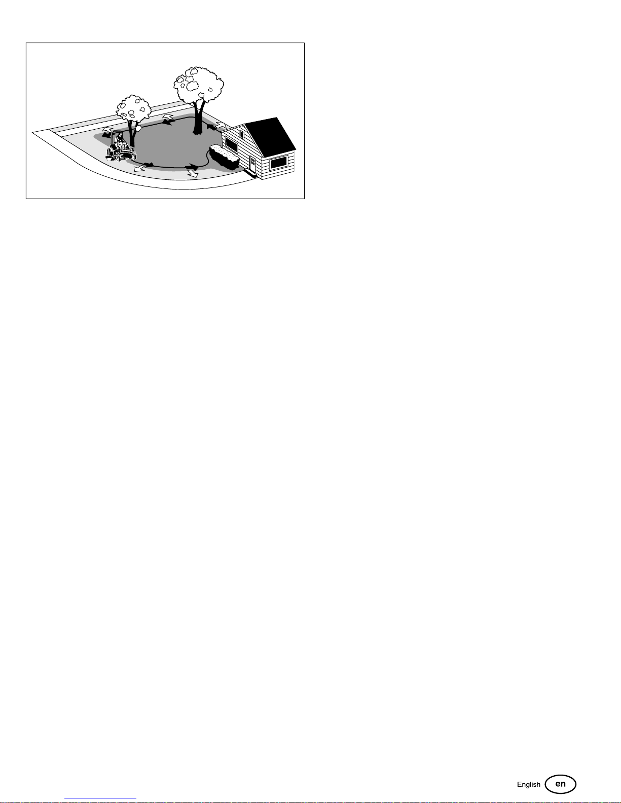
16
The remainder of the mowing should be done in the opposite
direction so that the clippings are dispersed OUT onto the area
of lawn previously cut.
Mowing Methods
Broadcast Mowing
Broadcasting, or side-discharging, disperses fine clippings
evenly over the entire lawn. Many golf courses use this method.
Your mower has a deep dish deck to allow freer circulation of
clippings so they are broadcast evenly over the lawn.
Engine Speed & Ground Speed for Broadcasting:
growth, and often wetter conditions are more suitable for
broadcasting (side-discharging) or grass bagging operation.
Engine Speed & Ground Speed for Mulching:
Use full engine throttle matched with a slow ground speed so
that clippings will be finely cut. Ground speed while mulching
should be HALF of the speed that would be used when
broadcasting (side discharging) under similar conditions. Since
mulching requires more horsepower than broadcasting, using
a slower ground speed is vitally important for proper mulching
operation.
How Much Grass to Mulch:
The best mulching action typically results from cutting only the
top ½ inch to 3/4 inch of grass blade. This provides short
clippings which decompose properly (much more quickly than
longer clippings). The ideal cutting height will vary with climate,
time of year, and quality of your lawn. We recommend that you
experiment with both the cutting height and ground speed until
you achieve the best cut. Start with a high cutting height and
using progressively lower settings until you find a cutting height
that is matched to your mowing conditions and preferences.
Pushing the Rider By Hand
NOTICE
Do NOT tow zero-turn rider.
Always operate the engine at full throttle when mowing. If you
hear the engine slowing down, you are mowing too fast—using
a slower ground speed will improve the cutting efficiency of the
blades and prevents many common cutting problems.
ALWAYS use an appropriate ground speed for the thickness
and height of the grass you are cutting (3rd gear or slower for
manual gear models). If you hear the engine slowing down you
are mowing too fast, use a slower ground speed.
How Much Grass to Cut Off When Broadcasting:
Mow when the grass is 3-5 inches long. Do not cut the grass
shorter than 2 to 2-1/2 inches. Do not cut off more that 1 inch
of grass in a single pass.
Mulching
Mulching consists of a mower deck which cuts and re-cuts
clippings into tiny particles and which then blows them down
INTO the lawn. These tiny particles decompose rapidly into
by-products your lawn can use. UNDER PROPER
CONDITIONS, your mulching mower will virtually eliminate
noticeable clippings on the lawn surface.
NOTE: When mulching under heavy cutting conditions, a
rumbling sound may be present and is normal.
Towing the units will cause hydraulic transmission damage.
Do not use another vehicle to push or pull this unit.
1. Disengage the PTO, engage the parking brake, turn the
ignition OFF, and remove the key.
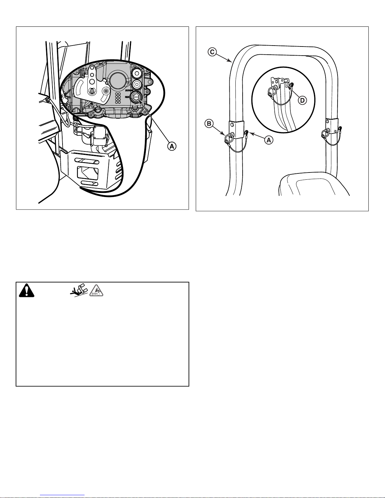
2. Open the hydraulic bypass valve (A, Figure 17). To open
the bypass valves, turn the bypass valve, which is located
on the side of the transmission, clockwise to the "open"
position (marked "bypass" on the transmission). See Figure
17 for valve location.
Mulching Requires EXCELLENT Mowing Conditions:
Mulching mowers cannot function properly if the grass is wet,
or if the grass is simply to high to cut. Even more than normal
mowing, mulching requires that the grass be dry and the
appropriate amount is cut.
Do not use the mower as a mulching mower during the first two
or three mowings in the spring. The long grass blades, quick
19
Page 20
17
18
3. Disengage the parking brake. The zero-turn rider can now
be pushed by hand.
4. After moving the zero-turn rider, re-engage the
transmissions by turning the bypass valves
counter-clockwise to the "closed" position (marked "run"
on the transmission).
Raise and Lower the Roll Bar
WARNING
Avoid serious injury or death from roll over:
• Keep roll bar in the raised position and use seat belt.
• There is no roll over protection when the roll bar is down.
• Lower the rollbar only when necessary and NEVER
remove it.
• Do NOT use seat belt when the roll bar is down.
• Raise the roll bar as soon as clearance permits.
• Do NOT jump off if mower tips.
To lower the roll bar:
2. Push or pull the top of the roll bar (C) forward against the
spring clips (D) and remove the retainer pins (B).
3. Lower the roll bar and reinstall the retainer pins and hair
pin clips to secure the roll bar in the down position (see
insert, Figure 18).
To raise the roll bar:
1. Pull the hair pin clips (A) out of the retainer pins (B) and
remove the retainer pins.
2. Raise the roll bar (C) until the top of the roll bar (C) contacts
the spring clips (D) on the upright tubes.
3. Push or pull the top of the roll bar forward against the spring
clips and reinstall the retainer pins and hair pin clips to
secure the roll bar in the raised position.
Attaching a Trailer
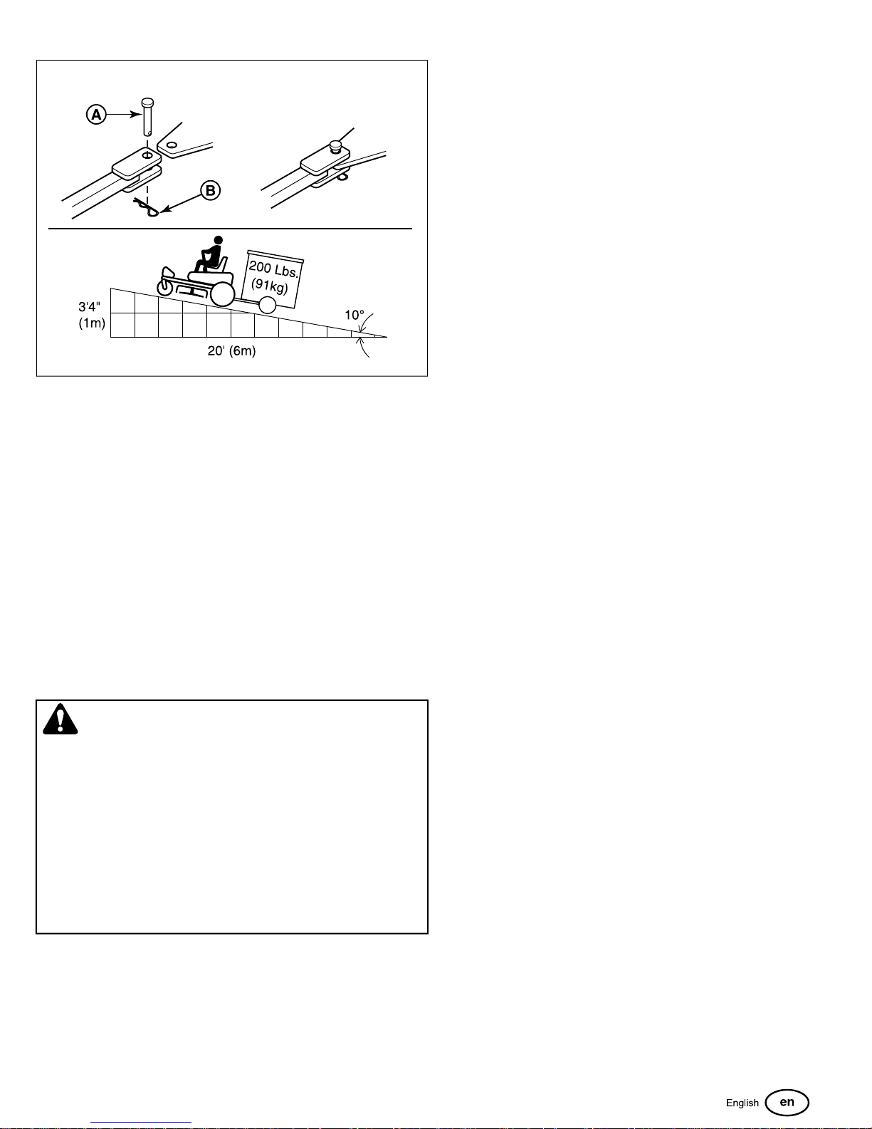
The maximum weight of a towed trailer should be less than 200
lbs (91kg). Secure the trailer with an appropriately sized clevis
pin (A, Figure 19) and clip (B).
1. Pull the hair pin clips (A, Figure 18) out of the retainer pins
(B).
20 ferrisindustries.com
Page 21
19
Excessive towed loads can cause loss of traction and loss of
control on slopes. Reduce towed weight when operating on
slopes. The surface being driven on greatly impacts traction
and stability. Wet or slippery surfaces can greatly reduce traction
and the ability to stop or turn. Carefully evaluate the surface
conditions before operating the unit and trailer, and never
operate on slopes greater than 10°. See SLOPE OPERATION
and TOWED EQUIPMENT in the safety section of this manual
for additional safety information.
Storage
Temporary Storage (30 Days or Less)
Remember, the fuel tank will still contain some gasoline, so
never store the unit indoors or in any other area where fuel
vapor could travel to any ignition source. Fuel vapor is also toxic
if inhaled, so never store the unit in any structure used for human
or animal habitation.
WARNING
Never store the unit, with gasoline in engine or fuel tank, in a
heated shelter or in enclosed, poorly ventilated enclosures.
Gasoline fumes may reach an open flame, spark or pilot light
(such as a furnace, water heater, clothes dryer, etc.) and
cause an explosion.
Handle gasoline carefully. It is highly flammable and careless
use could result in serious fire damage to your person or
property.
Drain fuel into an approved container outdoors away from
open flame or sparks.
Here is a checklist of things to do when storing your unit
temporarily or in between uses:
• Keep the unit in an area away from where children may
come into contact with it. If there’s any chance of
unauthorized use, remove the spark plug (s) and put in a
safe place. Be sure the spark plug opening is protected
from foreign objects with a suitable cover.
• If the unit can’t be stored on a reasonable level surface,
chock the wheels.
• Clean all grass and dirt from the mower.
Long Term Storage (Longer Than 30 Days)
Before you store your unit for the off-season, read the
Maintenance and Storage instructions in the Safety Rules
section, then perform the following steps:
1. Drain crankcase oil while engine is hot and refill with a grade
of oil that will be required when unit is used again.
2. Prepare the mower deck for storage as follows:
a.) Remove mower deck from the unit.
b.) Clean underside of mower deck.
c.) Coat all bare metal surfaces with paint or light coat of
oil to prevent rusting.
3. Clean external surfaces and engine.
4. Prepare engine for storage. See engine owner’s manual.
5. Clean any dirt or grass from cylinder head cooling fins,
engine housing and air cleaner element.
6. Cover air cleaner and exhaust outlet tightly with plastic or
other waterproof material to keep out moisture, dirt and
insects.
7. Completely grease and oil unit as outlined in the
section.
8. Clean up unit and apply paint or rust preventative to any
areas where paint is chipped or damaged.
9. Be sure the battery is filled to the proper level with water
and is fully charged. Battery life will be increased if it is
removed, put in a cool, dry place and fully charged about
once a month. If battery is left in unit, disconnect the
negative cable.
10. Drain fuel system completely or add a gasoline stabilizer
to the fuel system. If you have chosen to use a fuel stabilizer
and have not drained the fuel system, follow all safety
instructions and storage precautions in this manual to
prevent the possibility of fire from the ignition of gasoline
fumes. Remember, gasoline fumes can travel to distant
sources of ignition and ignite, causing risk of explosion and
fire.
Lubrication
NOTE: Gasoline, if permitted to stand unused for extended
periods (30 days or more), may develop gummy deposits
which can adversely affect the engine carburetor and cause
engine malfunction. To avoid this condition, add a gasoline
stabilizer to the fuel tank and run the engine a few minutes,
or drain all fuel from the unit before placing it in storage.
Starting After Long Term Storage
Before starting the unit after it has been stored for a long period
of time, perform the following steps.
1. Remove any blocks from under the unit.
2. Install the battery if it was removed.
3. Unplug the exhaust outlet and air cleaner.
4. Fill the fuel tank with fresh gasoline. See engine manual for
recommendations.
21
Page 22
5. See engine owner’s manual and follow all instructions for
preparing engine after storage.
6. Check crankcase oil level and add proper oil if necessary.
If any condensation has developed during storage, drain
crankcase oil and refill.
7. Inflate tires to proper pressure. Check fluid levels.
8. Start the engine and let it run slowly. DO NOT run at high
speed immediately after starting. Be sure to run engine only
outdoors or in well ventilated area.
Maintenance Procedures
Checking / Adding Fuel
WARNING
Gasoline is highly flammable and must be handled with care.
Allow engine to cool for at least 3 minutes before refueling.
Do not allow open flame, smoking or matches in the area.
Avoid over-filling and wipe up any spills.
Maintenance Schedule
UNIT MAINTENANCE
Before Each Use
Check Safety Interlock System
Check Rider Brakes
Check Rider / Mower for Loose Hardware
Check Hydraulic Oil Level
Every 25 Hours
Clean Deck & Check/Replace Mower Blades*
Lubricate Rider & Mower*
Check Tire Pressures
Every 100 Hours
Check Mower Blade Stopping Time
Clean Battery & Cables
Initial Change of Hydraulic Oil
Every 400 Hours
Change Hydraulic Oil & Filter
ENGINE MAINTENANCE
Before Each Use
Check Engine Oil Level
Every 25 Hours
Check/Clean Cooling Fins & Intake*
Every 50 Hours
Check/Clean Spark Arrester**
Refer to Engine Owner's Manual
Service Air Filter
Change Oil & Filter
Check/Replace Spark Plugs
Check/Replace Fuel Filter
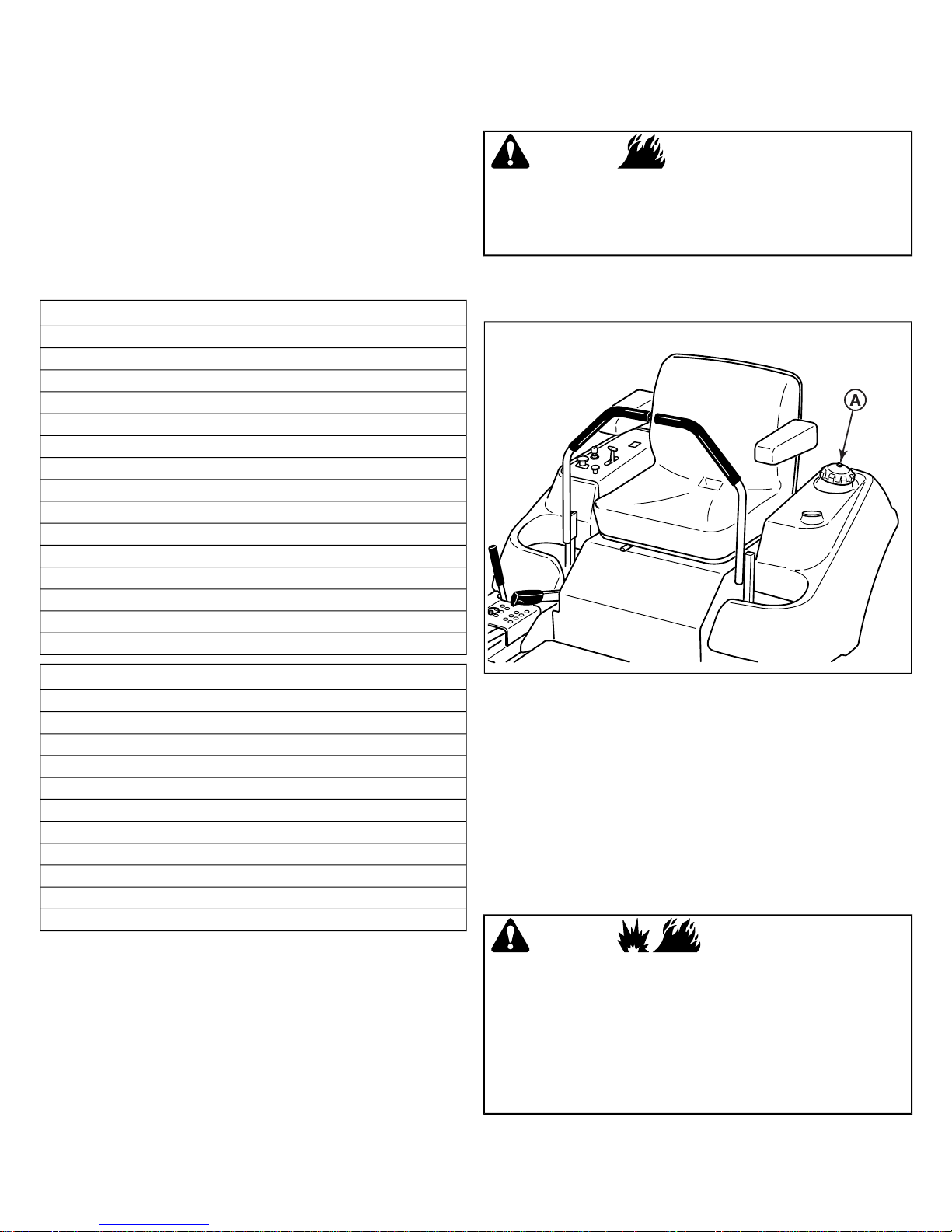
To add fuel:
1. Remove the fuel cap (A, Figure 20).
20
2. Fill the fuel tank to the bottom of the filler neck. This will
allow for fuel expansion.
Note: Do not overfill. Refer to your engine owner's manual
for specific fuel recommendations.
3. Install and hand tighten the fuel cap.
NOTICE
Refer to your engine owner's manual for specific fuel
recommendations.
Replacing the Fuel Filter
*More often in hot (over 85°F, 30°C) weather or dusty operating conditions.
**If equipped, replace if damaged.
WARNING
Fuel and its vapors are extremely flammable and
explosive.
Fire or explosion can cause severe burns or death.
Do NOT remove the fuel filter when the engine is hot, as
spilled gasoline may ignite. Do NOT spread hose clamps
further than necessary. Ensure clamps grip hoses firmly over
filter after installation.
Carbureated Models: The fuel filter is located in the fuel line
between fuel tank and carburetor, near the fuel pump.
22 ferrisindustries.com
Page 23
Fuel Injected Models: The fuel filter is located in the fuel line
between the fuel tank and fuel pump.
If filter is dirty or clogged, replace as follows:
1. Disconnect the negative battery cable.
2. Place a container below the filter to catch spilled fuel.
3. Using a pliers, open and slide hose clamps from fuel filter.
4. Remove hoses from filter.
5. Install new filter in proper flow direction in fuel line.
6. Secure with hose clamps.
7. Reconnect the negative battery cable when finished.
Check Engine Oil Level
Interval: Before Each Use
Refer to the engine owners manual for dipstick and oil fill
locations and specific engine oil check and fill procedures.
Changing the Engine Oil and Filter
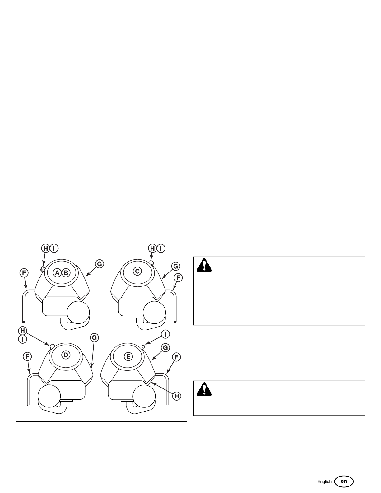
This series of mower has five different engine options: Briggs
& Stratton Vanguard Series (A, Figure 21), Briggs & Stratton
EFI Series (B), Kawasaki FX Series (C), Kohler EFI Series (D),
and Briggs & Stratton Vanguard Big Block Series (E). Please
reference figure 21 as the location of the components listed for
this procedure may vary by specific engine option.
21
2. Remove the oil drain hose (F) from its storage position and
route the hose so that when the oil drain cap is removed
the oil can be drained into a small pan.
3. Place a small pan under the oil drain hose to catch the oil.
Using the appropriate tools, remove the oil drain cap from
the oil drain hose and drain the engine oil.
4. After draining, replace the cap and wipe up any spilled oil.
Reinstall the oil drain hose to its storage position so it is
retained during normal operation.
5. Place an absorbent shop cloth under the engine oil filter
(G). Remove the engine oil filter and replace with a new
one.
6. Add engine oil (refer to engine operator’s manual) in the fill
tube (H) and check the amount of oil in the engine using
the engine oil dipstick (I).
7. Remove the shop cloth and wipe up any spilled oil.
Engine Maintenance
For engine maintenance schedules and procedures, please
refer to the engine operator's manual.
Electronic Fuel Injection (EFI) System - EFI
Models
EFI is an electronically-controlled fuel management system
which is monitored by an Electronic Control Unit (ECU). A
Malfunction Indicator Lamp (M.I.L.) will illuminate if problems
or faults are detected. Servicing by an authorized dealer is
necessary.
1. Warm engine by running for a few minutes. (Refer to the
engine operator’s manual for oil & filter replacement
instructions.)
CAUTION
Do not disconnect or reconnect ECU wiring harness connector
or any individual components with the ignition switch in the
"ON" position. This can send a damaging voltage spike
through the ECU.
Unplug harness from ECU before performing any welding on
equipment.
Inspect Muffler and Spark Arrester
Inspect the muffler for cracks, corrosion, or other damage.
Remove the spark arrester, if equipped, and inspect for damage
or carbon blockage. If replacement parts are required, make
sure to use only original equipment replacement parts.
WARNING
Replacement parts must be the same and installed in the
same position as the original parts or fire could result.
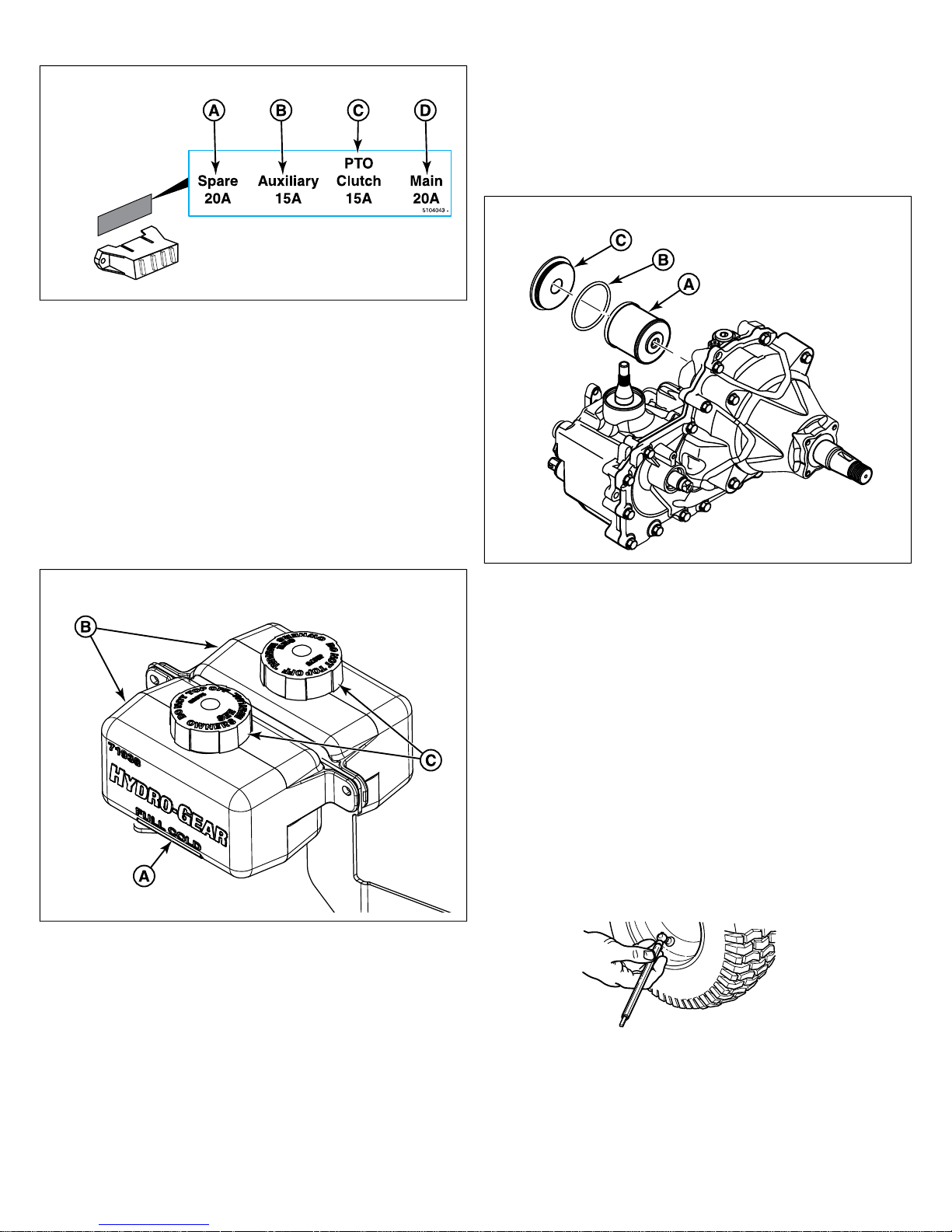
Fuse Identification and Location
The fuse block is located on the right side of the machine by
the instrument control panel. Refer to Figure 22for the location
and amperage of the fuses used in this machine.
23
Page 24
22
A. Spare: 20 amp fuse
B. Auxiliary: 15 amp fuse
C. PTO Clutch: 15 amp fuse
D. Main: 20 amp fuse
Check / Fill Transmission Oil Level
Oil Type: SAE 20W-50 motor oil
1. Check the oil level when the unit is cold. The oil should be
up to the "FULL COLD" mark (A, Figure 23) on the
transmission oil reservoirs (B). If the oil is below this level,
proceed to step 2.
NOTE: Removing the oil filter from the transmission will drain
the oil reservoir. Have a suitable container ready to catch any
spilled oil. The manufacturer recommends this be a dealer-only
service item.
1. Locate the hydraulic oil filter (A, Figure 24) on the side of
the transaxle.
24
23
2. Before removing the reservoir cap (C), make sure that the
area around the reservoir cap and fill neck of the reservoir
is free of dust, dirt, and other debris. Remove the reservoir
caps.
3. Add oil up to the "FULL COLD" mark.
4. Re-install the reservoir cap.
Change Hydraulic Oil Filter
Change Interval: Every 400 Hours (Initial hydraulic oil and filter
change after first 100 hours of operation)
2. Remove the filter cover (C) and o-ring (B).
3. Remove and discard the hydraulic filter.
4. Inspect all parts for wear or damage, replacing as
necessary.
5. Install the new filter, new o-ring and filter cover. Torque the
cover to 40-45 ft. lbs. (54-61 Nm).
NOTE: Use caution after changing the filter; air in the hydraulic
system may affect the responsiveness of the control levers.
Checking Tire Pressures
Tire pressure should be checked periodically, and maintained
at the levels shown in the Specifications chart. Note that these
pressures may differ slightly from the "Max Inflation" stamped
on the side-wall of the tires. The pressures shown provide proper
traction and extend tire life.
Lubrication
Lubricate the unit at the locations shown in Figures 25, 26, and
27 as well as the following lubrication points:
Filter Part Number: 5101987X2
24 ferrisindustries.com
Page 25
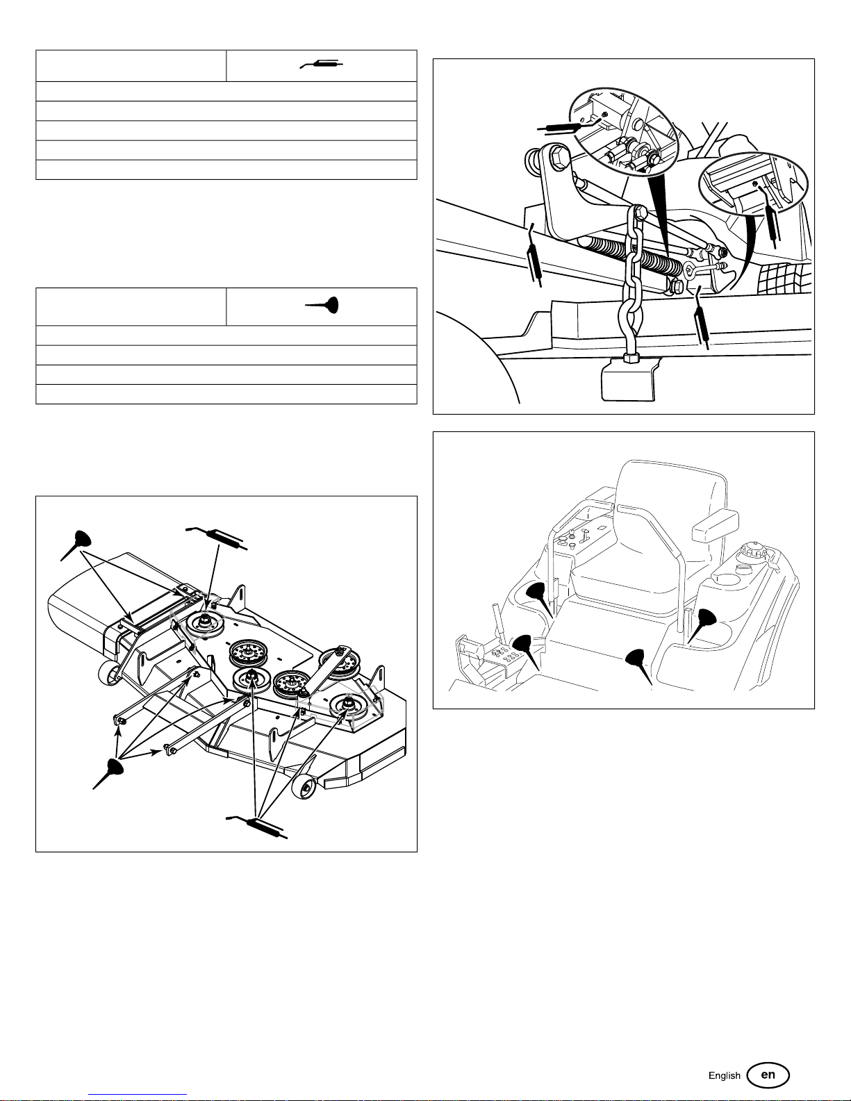
Grease
front caster wheel axles & yokes
deck lift pivot blocks
mower deck spindles
mower deck idler arm
transmission cradle pivot points
Use grease fittings when present. Disassemble parts to apply
grease to moving parts when grease fittings are not installed.
Not all greases are compatible. Red grease (p/n 5022285) is
recommended, automotive-type, high-temperature, lithium
grease may be used when this is not available.
Oil
control handle pivots
seat plate pivots
deck lift pivots
discharge chute hinge
Generally, all moving metal parts should be oiled where contact
is made with other parts. Keep oil and grease off belts and
pulleys. Remember to wipe fitting and surfaces clean both before
and after lubrication.
26
27
25
Lubricate the Front Casters
Interval: Annually
1. Remove the 1/4-28 bolt (A, Figure 28) screwed into the
caster and install a 1/4-28 grease fitting.
25
Page 26
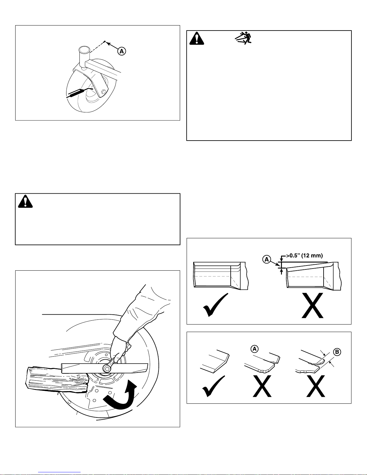
28
2. Grease the front caster.
3. Remove the 1/4-28 grease fitting and reinstall the 1/4-28
bolt.
4. Repeat the process for the other side of the machine.
Servicing the Mower Blades
Inspecting the Mower Blades
DANGER
Thrown objects hazard
Avoid injury: a worn or damaged mower blade can break and
a piece of the blade could be thrown into the operator's area
or bystander's area resulting in serious personal injury or
death.
• Inspect the mower blade every 25 hours or at least once
per year.
• If the mower blade hits a solid object, stop the engine
immediately and inspect the mower blades.
• Never weld or straighten bent mower blades.
1. Remove the mower blade from the unit. See Removing the
Mower Blades.
2. Inspect the mower blade (Figures 30 and 31). Discard the
mower blade if it has any of the following conditions:
Removing the Mower Blades
CAUTION
Laceration hazard
Mower blades are sharp.
Always wear gloves when handling, or working near, mower
blades.
1. Use a block of wood to prevent the mower blade from
turning as shown in Figure 29.
29
• More than .5" (12,7 mm) of the mower blade metal has
been removed from previous sharpening or wear (A,
Figure 30)
• The air lifts are excessively eroded (A, Figure 31) and
the notch (B) is .25" (6,35 mm) deep or greater.
• The mower blade is broken or bent.
30
31
3. If the cutting edges are not sharp or have nicks, sharpen
the blades. See Sharpening the Mower Blades.
2. Using a wrench, remove the bolt securing the blade to the
spindle.
26 ferrisindustries.com
Page 27
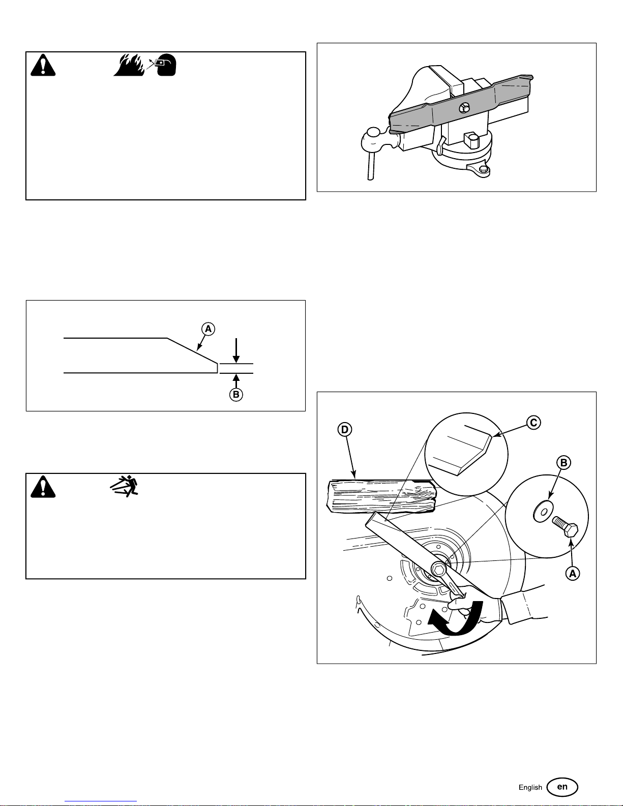
Sharpening the Mower Blades
WARNING
Thrown objects and fire hazard
Grinding mower blades throws sparks and fine metal particles
that are capable of igniting gasoline and gasoline vapors, and
that can injure unprotected eyes.
Be sure all flammable materials are cleared from the area
where grinding will occur.
Always wear safety glasses or goggles when grinding mower
blades.
1. Sharpen mower blades with a grinder, hand file, or electric
blade sharpener.
2. Sharpen the blade by removing an equal amount of material
from the cutting edge of each end of the blade.
3. Keep the original bevel (A, Figure 32) when grinding. DO
NOT change the mower blade bevel.
32
33
3. Check the balance of the mower blade. If either end of the
mower blade moves downward is heavier than the other.
Sharpen the heavy end until balance is achieved. See
Sharpening the Mower Blades for sharpening instructions.
4. Repeat the process until the mower blade remains in the
horizontal, level position.
Installing Mower Blades
1. Reinstall each mower blade with the air lifts (C, Figure 34)
pointing up towards the mower deck as shown in Figure
34. Secure with the mower blade mounting bolt and flat
washer (A & B). Wedge a wooden block (D) between the
mower blade and the mower deck housing to keep the
mower blade from turning and torque to 70 ft. lbs (94 Nm).
4. The mower blade should have a maximum of 1/64" (0,40
mm) cutting edge (B) or less.
Balancing the Mower Blades
CAUTION
Thrown objects hazard
An unbalanced mower blade can create excessive vibration
and damage the unit, or cause mower blade failure resulting
in thrown debris.
Be sure blade is balanced before installing.
1. Clean the mower blade to remove any dried grass or other
debris.
2. Clamp a nail in a bench vise, hang the mower blade on the
nail, and position the blade in a level horizontal position as
shown in Figure 33.
34
Seat Adjustment
The seat can be adjusted forward and back. Move the lever (A,
Figure 35) towards the left, position the seat as desired, and
release the lever to lock the seat into position.
27
Page 28
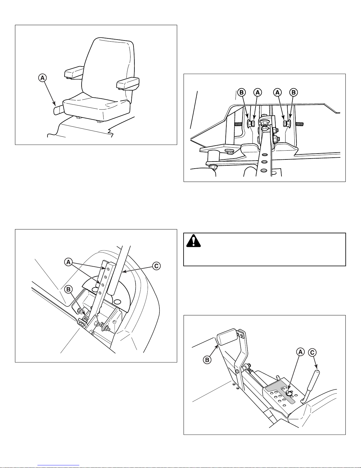
35
Ground Speed Control Lever Adjustment
The control levers can be adjusted in three ways. The alignment
of the control levers, the placement of the levers (how close the
ends are to one another) and the height of the levers can be
adjusted.
To Adjust the Handle Alignment
Loosen the mount bolts (A, Figure 36) and pivot the lever(s) (C)
to align with each other.
36
Speed Balancing Adjustment
If the rider veers to the right or left when the ground speed
control levers are in the maximum forward position, the top
speed of each of these levers can be balanced by turning the
adjustment bolt(s) (A, Figure 37). Only adjust the speed of the
wheel that is traveling faster.
37
To Reduce the Speed of the Faster Wheel
1. Loosen the securing nut (B).
2. Turn the top speed adjustment bolt counter-clockwise to
reduce the speed.
3. Retighten the securing nut when adjustment is complete.
To Adjust the Handle Placement
Loosen the jam nuts and adjust the placement bolt (B) in or out
to properly adjust the lever end spacing.
To Adjust the Handle Height
Remove the mounting hardware and reposition the handle either
up or down from its original position. You will need to readjust
the handle alignment as described above.
WARNING
DO NOT adjust the tractor for a faster overall speed
forward or reverse than it was designed for.
Mowing Height Adjustment
The cutting height adjustment pin (A, Figure 38) controls the
mower cutting height. The cutting height is adjustable between
1-3/4” (4,4 cm) and 5” (12,7 cm) in 1/4” (0,64 cm) increments.
38
28 ferrisindustries.com
Page 29
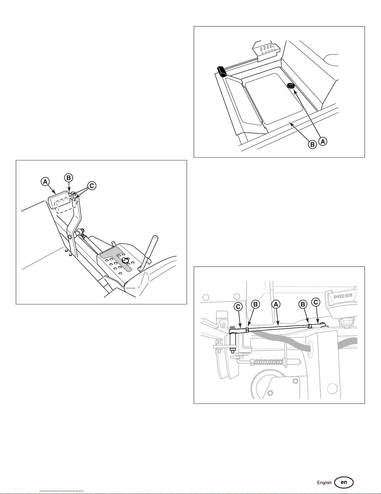
1. Depress the deck lift foot pedal (B) until it locks into the 5”
(12,7 cm) position.
2. Place the cutting height adjustment pin in the desired cutting
height.
3. Depress the deck lift foot pedal then push the lock lever (C)
towards the right to release the lock.
4. Release the deck lift foot pedal until it comes to rest against
the cutting height adjustment pin.
Foot Pedal Adjustment
The deck lift foot pedal can be adjusted to accommodate the
operator’s height for optimal comfort.
To adjust pedal position:
1. Remove the foot pedal (A, Figure 39) from the pedal mount
tab (B).
40
39
2. Remove the pedal mount hardware (C) and rotate the tab
180 degrees.
3. Reinstall the pedal mount hardware and tighten securely.
4. Reinstall the foot pedal on the pedal mount tab in the proper
orientation as shown in Figure 39.
2. Tilt the back end of the floor pan up and then remove it from
the unit.
3. To re-install the floor pan: Reverse the removal procedure.
Neutral Adjustment
The neutral system for this mower consists of two neutral linkage
rods and a pivot that connects the ground speed control lever
to the transmission. The lower rod that connects the
transmission to the pivot is factory preset and should not be
changed for neutral adjustment purposes. The adjustment is
achieved by changing the length of the upper rod (A, Figure 41)
that connects the ground speed control lever to the pivot.
41
Floor Pan Removal & Installation
This unit is equipped with a removable floor pan which can be
removed to provide better access to the mower deck.
1. Loosen and remove the retaining hardware (A, Figure 40)
that secures the floor pan to the frame of the unit.
Determining if Adjustment is Necessary: If the tractor
"creeps" while the ground speed control levers are locked in
the NEUTRAL, then it may be necessary to adjust the linkage
rods.
NOTE: Perform this adjustment on a hard, level surface such
as a concrete floor.
29
Page 30
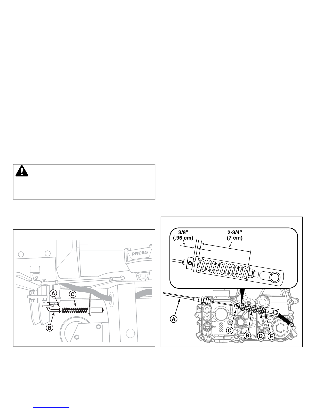
1. Disengage the PTO, engage the parking brake and turn off
the engine.
2. There are two nuts (B) on the linkage rod. Loosen the nuts
from the ball joints (C) and turn the linkage rod to adjust.
• If the machine creeps forward, turn the rod clockwise
(while standing at the rear of the machine, facing
forward);
• If the machine creeps backward, turn the rod
counter-clockwise (while standing at the rear of the
machine, facing forward).
3. Lock the jam nut against the ball joints when neutral is
achieved.
NOTE: This adjustment should not be performed while the
machine is running. It may take several attempts to achieve
neutral, depending on how much the machine creeps.
Return-to-Neutral Adjustment
Prior to performing this procedure the
procedure must be completed.
WARNING
To avoid serious injury, perform adjustments only with the
engine stopped, ignition key removed, and zero-turn rider
parked on level ground.
1. Lock the ground speed control lever in the neutral position.
2. Loosen the set collar (A, Figure 42) on the neutral return
rod (B).
Neutral Adjustment
5. Move the ground speed control levers out towards the
neutral position.
• if the ground speed control lever aligns with the notch
in the neutral lock plate, adjustment is complete.
• if the ground speed control lever stops it's return motion
past the notch (while standing at the rear of the
machine), reposition the set collar so the neutral return
spring is less compressed.
• if the ground speed control lever stops it's return motion
before the notch (while standing at the rear of the
machine), re-position the set collar so that the neutral
return spring is more compressed.
6. Repeat the process as necessary until the ground speed
control lever aligns with the notch in the neutral lock plate.
NOTE: It is important to note that after every adjustment of the
neutral return rod, the lever must be pulled rearward and
released to properly check the return-to-neutral position.
Parking Brake Adjustment
The parking brake mechanism consists of two parking brake
cables (A, Figure 43) that connect the parking brake lever shaft
to the parking brake control arm on the transmissions. There is
a parking brake spring on each parking brake cable located
below the engine deck by the transmission. The position of the
parking brake cable in the rear suspension cradle is factory
preset and should not be changed for parking brake adjustment
procedures. The adjustment is achieved by changing the
compressed spring length of the parking brake springs.
43
42
3. Position the set collar along the neutral return rod until it
contacts and very lightly compresses the neutral return
spring (C). Tighten the set collar.
4. Move the ground speed control levers into the operating
position, pull rearward, and release.
1. Disengage the PTO, engage the parking brake, stop the
engine, and chock the tires.
2. Locate the parking brake springs (B) by the transmissions.
30 ferrisindustries.com
Page 31
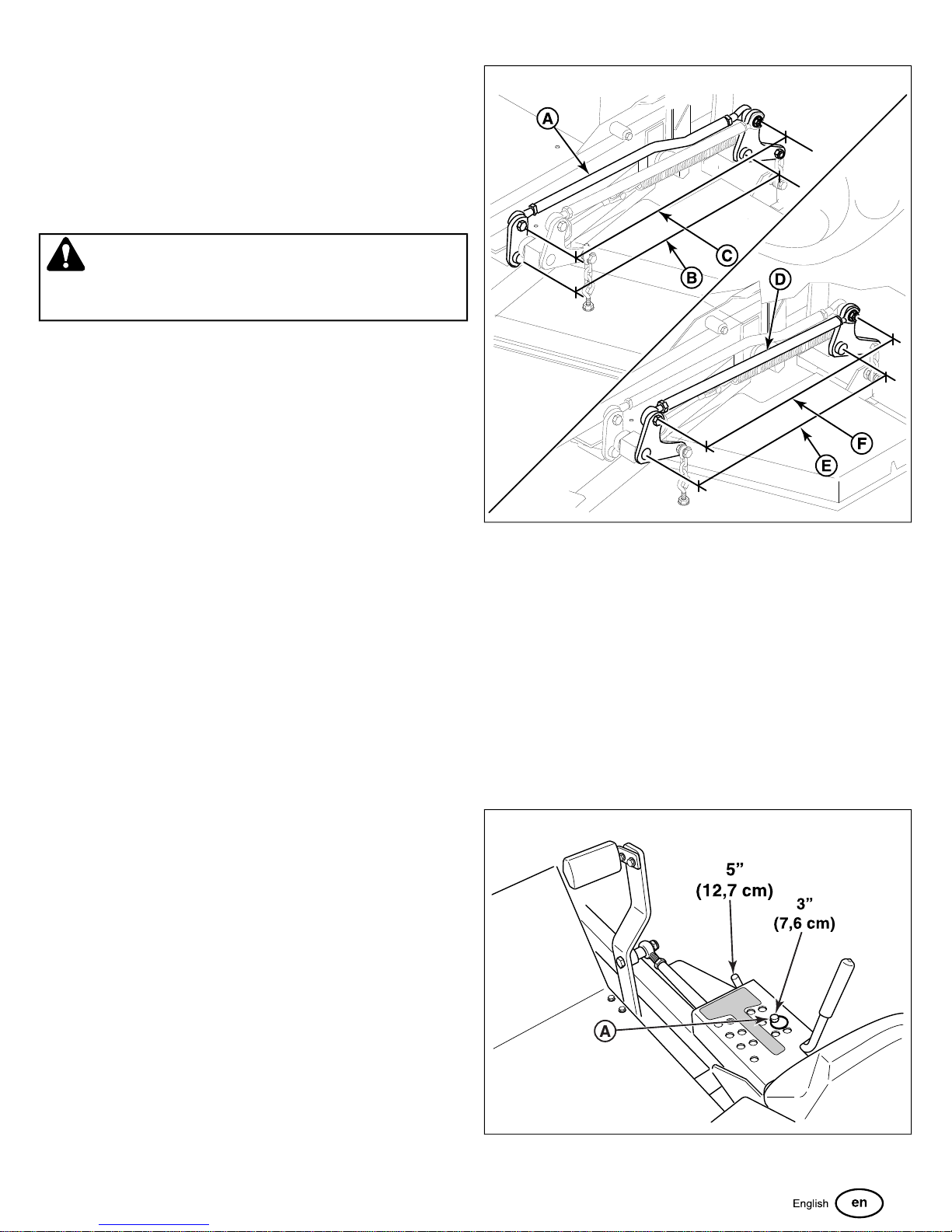
3. With the parking brake engaged measure the compressed
spring length. The spring should measure 2-3/4" (7 cm)
when compressed.
4. If the spring length does not equal the measurement, the
spring length will need to be adjusted.
5. Disengage the parking brake.
6. Loosen the set collar (C) and slide it away from the back of
the parking spring bracket (D).
CAUTION
Do not adjust the spring to be shorter than 2-1/2" (6.4 cm)
when compressed. This may damage the brake mechanism.
7. Turn the adjustment nut (E) to compress or release the
spring.
8. Engage the parking brake and re-measure the spring.
Continue this process until the compressed spring length
measures 2-3/4" (7 cm).
9. Position the set collar 3/8" (0,96 cm) away from the parking
brake bracket and tighten.
If this does not correct the braking problem, see your
dealer.
44
Deck Lift Rod Timing Adjustment
Checking the Deck Lift Rod Timing
1. Park machine on a flat, level surface. Disengage the PTO,
stop the engine, and engage the parking brake. Verify the
tires are inflated to the correct pressure.
2. To check the inner lift rod (A, Figure 44) timing, measure
and record the distance between the inner lift pivots (B) and
the inner rod pivots (C). Repeat for other side of unit.
3. To check the outer lift rod (D) timing, measure and record
the distance between the outer lift pivots (E) and the outer
rod pivots (F). Repeat for other side of unit.
4. If the measurements for the inner rods are equal, and the
measurements for the outer rods are equal, no further
adjustment is required. If the measurements are NOT equal
(greater than 1/8” (3,17 mm) difference), adjustment is
required, continue with Adjusting the Deck Lift Rod Timing.
Adjusting the Deck Lift Rod Timing
1. Lock the deck lift pedal in the 5” (12,7cm) position. Remove
the height adjustment pin (A, Figure 45) and lower the
mower deck.
45
2. To ensure that the deck is in the lowest position, push the
pedal by hand towards the rear of the unit and install the
31
Page 32
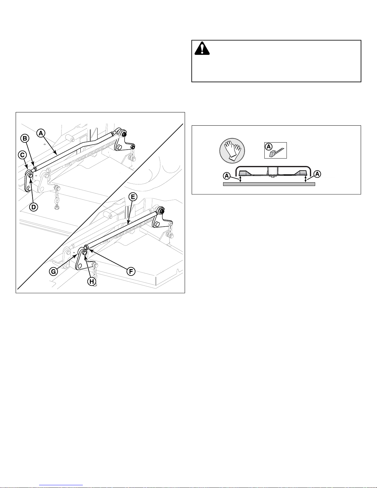
height adjustment pin in the 3” (7.6 cm) position to hold in
place.
3. Block up the mower deck until all hanger chains are slack.
4. To adjust the inner lift rod (A, Figure 46): Loosen the jam
nut (B) on the front ball joint (C) then remove the 1/2”
hardware (D) fastening the ball joint to the lift pivot arm.
Turn the ball joint clockwise to shorten the distance
between the rod pivots or counter-clockwise to lengthen
the distance between the rod pivots. Reinstall the ball joint
on the lift pivot arm and secure with the 1/2” hardware
previously removed. Tighten the jam nut against the lift rod.
46
Determining if the Deck Leveling Needs to Be
Adjusted
WARNING
Avoid Injury! Mower blades are sharp.
Always wear gloves when handling blades or working near
blades.
1. Place the deck height adjustment pin in the 4" (10,2 cm)
position.
2. See Figure 47. Position the outside mower blades so they
face front-to-back.
47
3. Measure the front tip (A) of the blade from the cutting edge
to the ground.
4. Measure the rear tip (A) of the blade from the cutting edge
to the ground.
5. To adjust the outer lift rod (E): Loosen the jam nut (F) on
the front ball joint (G) then remove the 1/2” hardware (H)
fastening the ball joint to the lift pivot arm. Turn the ball joint
clockwise to shorten the distance between the rod pivots
or counter-clockwise to lengthen the distance between
the rod pivots. Reinstall the ball joint on the lift pivot arm
and secure with the 1/2” hardware previously removed.
Tighten the jam nut against the lift rod.
6. Remove blocks from under the mower deck.
7. Remove the cutting height adjustment pin from in front of
the deck lift pedal arm. Lift mower deck and reinstall
adjustment pin in desired mowing height.
Deck Leveling Adjustment
Before adjusting the deck level, the deck lift rod timing must be
checked and/or adjusted.
• the front and rear measurements should equal 4" (10,2
cm).
If the measurements are greater than 1/8" (3,17 mm) of
what they should be, adjust the deck leveling.
Deck Leveling Adjustment
1. Place the deck height adjustment pin in the 4" (10,2 cm)
position.
2. Place 2 X 4 blocks under each corner of the mower deck
with the 3-1/2" sides being vertical.
Coarse Adjustment
1. Loosen the nuts (D, Figure 48) and allow the front of the
deck to rest on the 2 X 4's. Slide the chains in the slots until
the chains are tight and tighten the nuts.
32 ferrisindustries.com
Page 33
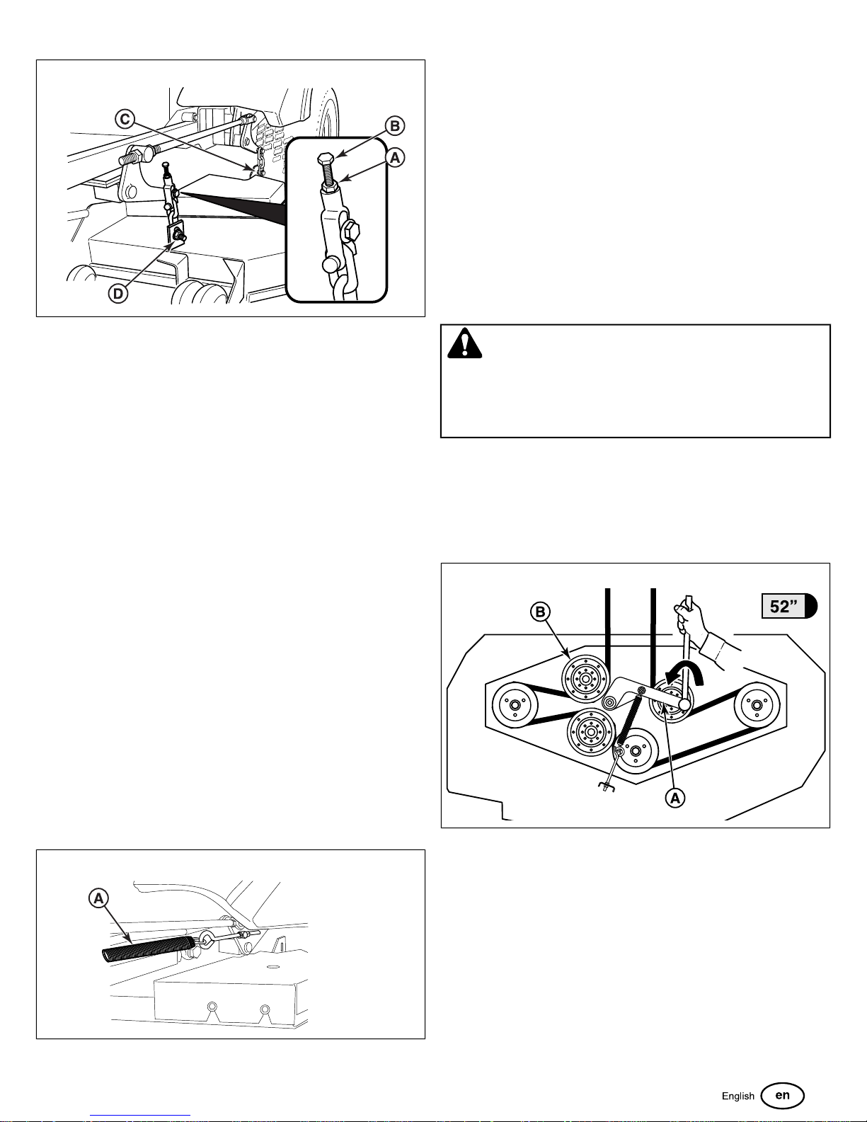
48
2. Loosen the nuts (C) and allow the rear of the deck to rest
on the 2 X 4's. Slide the chains in the slots until the chains
are tight and tighten the nuts.
3. Repeat the process for the other side of the unit.
4. Remove all the blocks from under the mower deck.
5. Perform the
Adjusted
correctly.
• If the measurements are greater than 1/8" (3,17 mm)
of what they should be perform the
procedure.
Determining if the Deck Leveling Needs to Be
procedure to verify that the deck has been levelled
Fine Adjustment
Although it is fastened with a multi-position anchor, this is not
an adjustment point.
Do NOT attempt to adjust the spring length or lifting performance
will be compromised.
Mower Belt Replacement
NOTICE
1. Park the mower on a smooth level surface such as a
concrete floor. Disengage the PTO, engage the parking
brake, turn off the engine and remove the ignition key.
2. Lower the mower deck to its lowest cutting position and
remove the mower deck guards and floor pan to gain access
to the mower deck belt.
Use extreme caution when rotating the idler arm with the
breaker bar, due to the increased tension in the spring as the
idler arm is being rotated. Injury may result if the breaker bar
is prematurely released while the spring is under tension.
3. Using a 1/2" breaker bar, place the square end in the square
hole located in the end of the idler arm (A, Figures 50 & 51)
To avoid damaging belts, do not pry over pulleys.
WARNING
• For 52" Models: Carefully rotate the breaker bar
counter-clockwise, which will relieve the tension on
the belt exerted from the idler arm.
Fine Adjustment
1. Loosen the jam nut (A, Figure 48) and turn the fine
adjustment bolt (B) to adjust the deck height
• Turn the bolt clockwise to raise the deck
• Turn the bolt counter-clockwise to lower the deck.
2. Once the desired measurement is achieved, retighten the
jam nut.
3. Repeat the process for the other side of the unit.
Deck Lift Assist Springs
Some models are equipped with deck lift assist springs (A,
Figure 49) that assist the operator in raising the mower deck
with the deck lift pedal. The deck lift assist springs are factory
set to provide optimal lifting performance.
49
50
• For 61" Models: Carefully rotate the breaker bar
clockwise, which will relieve the tension on the belt
exerted from the idler arm.
33
Page 34
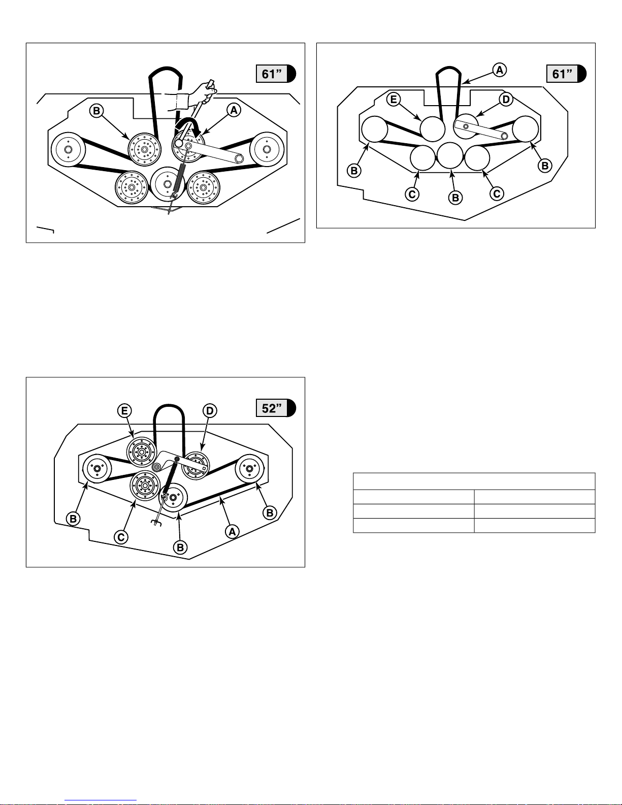
51
53
4. Slide the drive belt over the edge of the rear stationary idler
pulley (B, Figures 50 & 51). Carefully release the tension
on the breaker bar.
5. Remove the old belt and replace with a new one. Make sure
that the V-side of the belt runs in the pulley grooves.
6. Install the drive belt (A, Figures 52 & 53) on the PTO pulley,
the spindle pulleys (B), the front stationary idler pulley(s)
(C), and the adjustable idler pulley (D), except the rear
stationary pulley (D).
52
• For 52" Models: Carefully rotate the breaker bar
counter-clockwise and install the belt on the rear
stationary idler pulley.
• For 61" Models: Carefully rotate the breaker bar
clockwise and install the belt on the rear stationary
idler pulley.
7. Carefully release the tension on the breaker bar.
8. Reinstall the mower deck guards.
9. Run the mower under no-load condition for about 5 minutes
to break-in the new belt.
Check the Mower Belt Idler Tensioner Spring
Length
1. Set the mower deck to the 3-1/2" (8.9 cm) cutting position.
2. Use the
determine the correct spring length for your unit.
Mower Belt Idler Tensioner Spring Length
Mower Belt Idler Tensioner Spring Length
MeasurementDeck Size
11-9/16" (29.4 cm)52" Mower Deck
6-3/4" (17.12 cm)61" Mower Deck
chart to
3. Measure the coil length (A, Figure 54) of the mower belt
idler tensioner spring (B). The measurement should equal
the measurement as indicated in the chart. If the
measurement does not equal the measurement as indicated
in the chart, perform the
Tensioner Spring Length
34 ferrisindustries.com
Adjusting the Mower Belt Idler
procedure.
Page 35
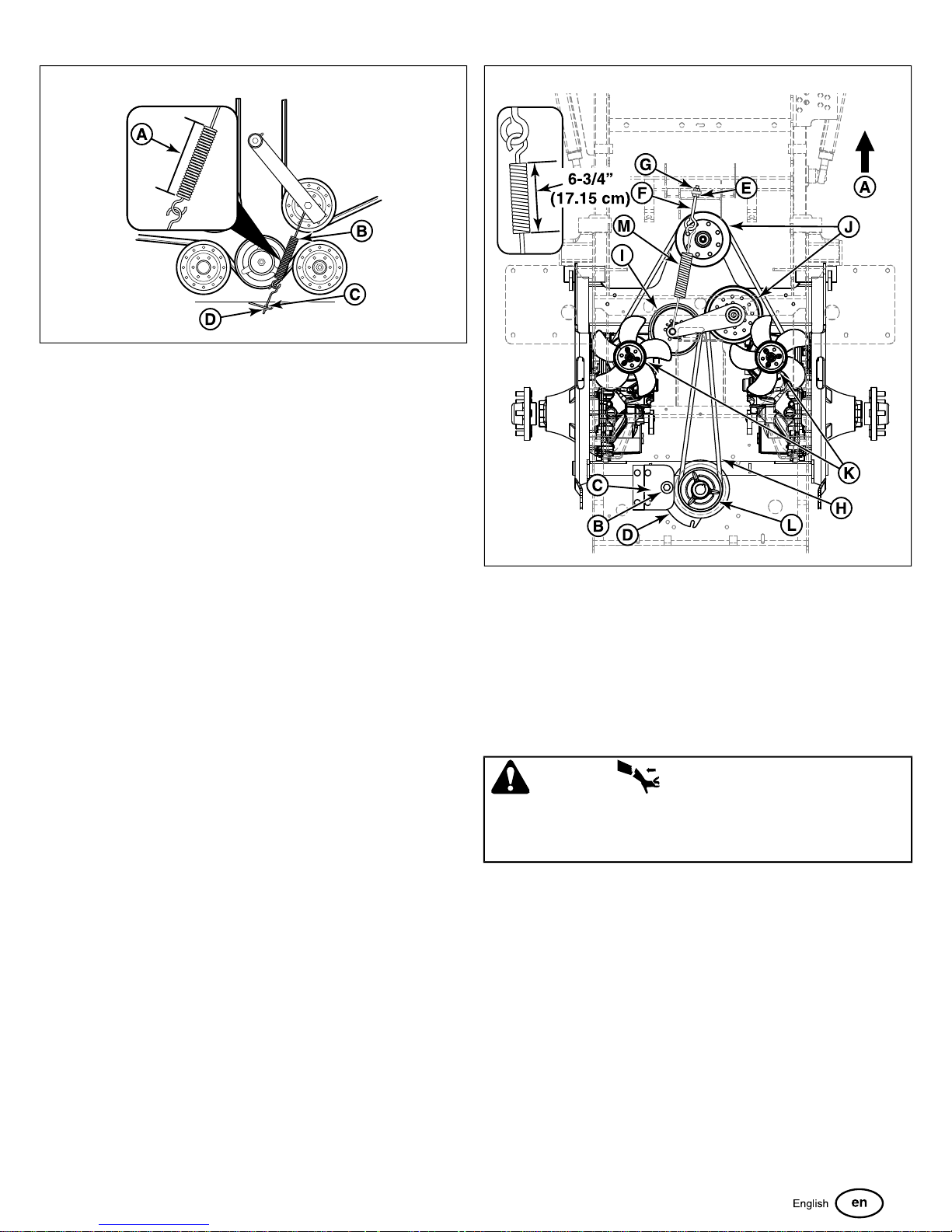
54
Adjusting the Mower Belt Idler Tensioner Spring
Length
1. Loosen the jam nut (C, Figure 54) on the eye bolt (D).
2. Turn the adjustment nut (E) until the measurement as
indicated in the chart is achieved.
3. Re-tighten the jam nut.
4. Re-install the mower deck guards and floor pan.
5. Run the mower under no-load condition for about five (5)
minutes to break in the new belt.
Transmission Drive Belt Replacement
The illustration depicts the transmission drive belt setup as seen
from the top side of the unit and the arrow (A, Figure 55)
indicates the front of the unit.
55
1. Park the zero-turn riding mower on a smooth, level surface
such as a concrete floor. Disengage the PTO, engage the
parking brake, turn off the ignition, and remove the key.
2. Remove the mower belt. See
Replacement
3. Remove the hardware (B) that secures the clutch anchor
pad (C) to the PTO clutch (D) and disconnect the wire
harness from the PTO clutch.
for removal instructions.
Mower Drive Belt
WARNING
STORED ENERGY DEVICE: Improper release of the belt
tension spring can result in personal injury. Use extreme
caution when removing the spring.
4. Loosen the jam nut (E) on the spring anchor eye bolt (F).
5. Loosen the adjustment nut (G) on the spring anchor eye
bolt to release the majority of the belt tension. Use caution
to remove the nut to completely release the tension.
6. Remove the old belt and replace with a new one (H). Make
sure the V-side of the belt runs in the grooves of the
adjustable idler pulley (I), the front stationary idler pulleys
(J), both transmission pulleys (K), and the crankshaft pulley
(L).
7. Re-install the spring anchor eye bolt into the spring anchor
tab and loosely fasten the adjustment nut.
8. Tighten the nut until the spring (M) achieves a coil-to-coil
measurement of 6-3/4" (17.15 cm).
9. Tighten the jam nut.
35
Page 36
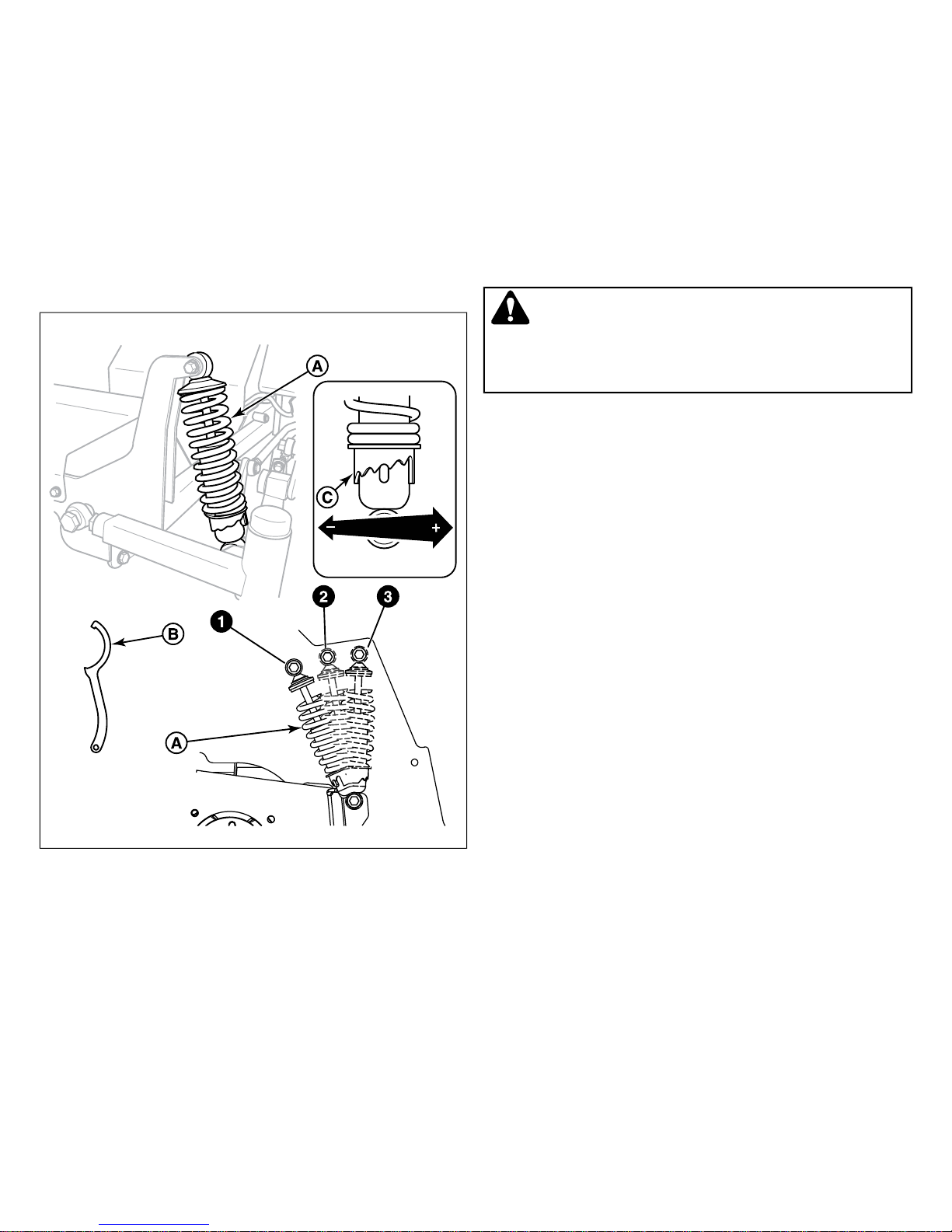
10. Re-install the clutch anchor pad to the PTO clutch and
secure using the hardware previously removed. Reconnect
the wire harness to the PTO clutch.
11. Re-install the mower belt. See
Replacement
for re-installation instructions.
Mower Drive Belt
• Shock mounting position #3 should always be used when
a rear mounted grass collection system is installed on the
unit.
To Adjust the Spring Pre-load:
Suspension Adjustment
The shock assemblies (A, Figure 56) can be adjusted in two
ways to allow the operator to customize the ride according to
the operator's weight and/or operating conditions. You have the
option of adjusting the spring pre-load and/or the upper mounting
position.
56
1. Park the machine on a flat, level surface. Disengage the
PTO, stop the engine, and engage the parking brake.
2. Chock the front wheels to prevent the machine from rolling.
Raise the rear of the machine and secure with jack stands.
3. Remove the rear drive tires.
WARNING
Spring loaded components can kick back causing injury. Use
two hands when adjusting the shock springs. This will prevent
the wrench from slipping while pressure is being applied.
4. Using the supplied spanner wrench (p/n 5022853) (B, Figure
56), insert the tip of the wrench into the notch in the pre-load
adjuster. While holding the wrench in place with one hand,
turn counter-clockwise to increase the pre-load, turn
clockwise to decrease the pre-load. Make sure both shocks
are set to the same amount of pre-load.
5. Re-install the rear drive tires. Torque the lug bolts to 85-95
ft.lbs. (115-129 Nm). Remove the jack stands from under
the machine.
NOTE: If a collection system is installed on the unit it is
recommended that the rear suspension be adjusted stiffer due
to the added weight of the collection system.
Items to consider be adjusting the suspension:
• Less spring pre-load should be used with light weight
operators, which will provide a softer, more cushioned ride.
• More spring pre-load should be used with heavy weight
operator's , which will provide a stiffer, more rigid ride.
• There are three positions in which the upper shock mount
can be positioned in. If adjusting the spring pre-load does
not achieve the ride requirement, the shock should be
moved to the next numbered upper shock mounting position
to achieve the desired ride requirement.
• Before adjusting the upper shock mount to a higher
numbered position, you should attempt to achieve the ride
height through the spring pre-load adjustment.
To Adjust the Upper Mounting Position (Rear
Shocks):
1. Park the machine on a flat, level surface. Disengage the
PTO, stop the engine, and engage the parking brake.
2. Chock the front wheels to prevent the machine from rolling.
Raise the rear of the machine and secure with jack stands.
The jack stands must be under the bumper of the machine.
3. Position the jack underneath the rear cross member of the
transmission cradle and slowly raise the rear suspension
to relieve the pressure on the upper shock mounting bolts.
4. Remove the upper shock mounting hardware and pivot the
shock to the next higher numbered position (see Figure 56).
Adjust the jack to align the shock mounts to shocks.
5. Remove the jack from under the transmission cradle.
6. Remove the jack stands from underneath the machine.
Battery Maintenance
This unit is equipped with a maintenance-free BCIU1 battery.
36 ferrisindustries.com
Page 37
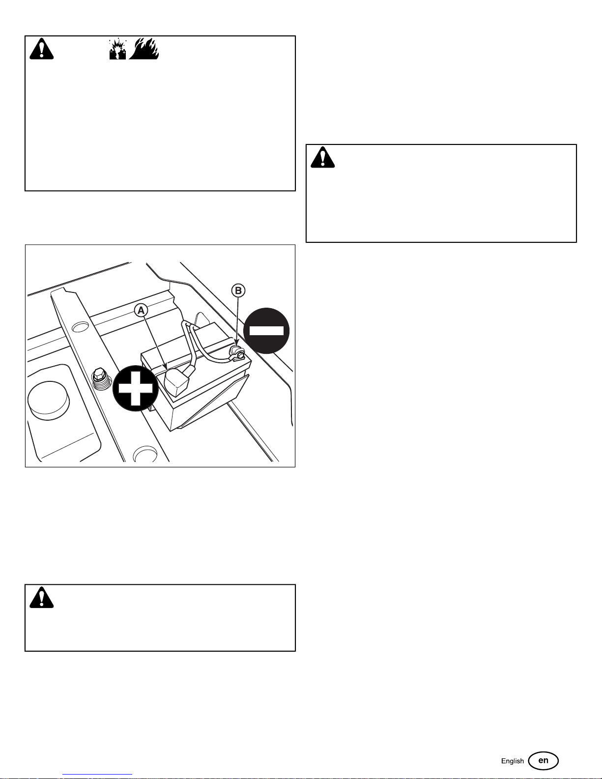
WARNING
Keep open flames and sparks away from the battery.
• Be careful when handling the battery.
• Avoid spilling electrolyte.
• Keep flames and sparks away from the battery.
• When removing or installing battery cables, disconnect
the negative cable FIRST and reconnect it LAST. If not
done in this order, the positive terminal can be shorted to
the frame by a tool.
Cleaning the Battery and Cables
1. Disconnect the cables from the battery, negative [-] cable
first (B, Figure 57).
A dead battery or one too weak to start the engine may not
mean the battery needs to be replaced. For example, it may
mean that the alternator is not charging the battery properly. If
there is any doubt about the cause of the problem, see your
dealer. If you need to replace the battery, follow the steps under
Cleaning the Battery & Cables in the Regular Maintenance
Section.
Charging a Completely Discharged Battery
WARNING
• Do NOT charge battery with key switch ON.
• Never use a quick battery charger to start engine.
• Always disconnect negative (-) battery cable before
charging battery,
57
2. Clean the battery terminals and cable ends with a wire brush
until shiny.
3. Reinstall the battery and reattach the battery cables, positive
[+] cable first (A).
4. Coat the cable ends and the battery terminals with
petroleum jelly or non-conducting grease.
Battery Service
1. Be aware of all the safety precautions you should observe
during the charging operation. If you are unfamiliar with the
use of a battery charger and hydrometer, have the battery
serviced by your dealer.
2. Add distilled water sufficient to cover the plate (fill to the
proper level near the end of the charge). If the battery is
extremely cold, allow it to warm before adding water
because the water level will rise as it warms. Also, an
extremely cold battery will not accept a normal charge until
it becomes warm.
3. Always unplug or turn the charger off before attaching or
removing the clamp connections.
4. Carefully attach the clamps to the battery in proper polarity
(usually red to [+] positive and black to [-] negative).
5. While charging, periodically measure the temperature of
the electrolyte. If the temperature exceeds 125° F (51.6°
C), or if violent gassing or spewing of electrolyte occurs,
the charging rate must be reduced or temporarily halted to
prevent battery damage.
6. Charge the battery until fully charged (until the specific
gravity of the electrolyte is 1.250 or higher and the
electrolyte temperature is at least 60° F). The best method
of making certain a battery is fully charged, but not over
charged, is to measure the specific gravity of a cell once
per hour. The battery is fully charged when the cells are
gassing freely at low charging rate and less than 0.003
change in specific gravity occurs over a three hour period.
WARNING
Keep open flames and sparks away from the battery; the
gasses coming from it are highly explosive. Ventilate the
battery well during charging.
Checking Battery Voltage
A voltmeter can be used to determine condition of battery. When
engine is off, the voltmeter shows battery voltage, which should
be 12 volts. When engine is running, the voltmeter shows
voltage of charging circuit which normally is 13 to 14 volts.
Jump Starting With Auxiliary (Booster) Battery
Jump starting is not recommended. However, if it must be done,
follow these directions. Both booster and dis-charged batteries
should be treated carefully when using jumper cables. Follow
the steps below EXACTLY, being careful not to cause sparks.
Refer to Figure 58.
37
Page 38
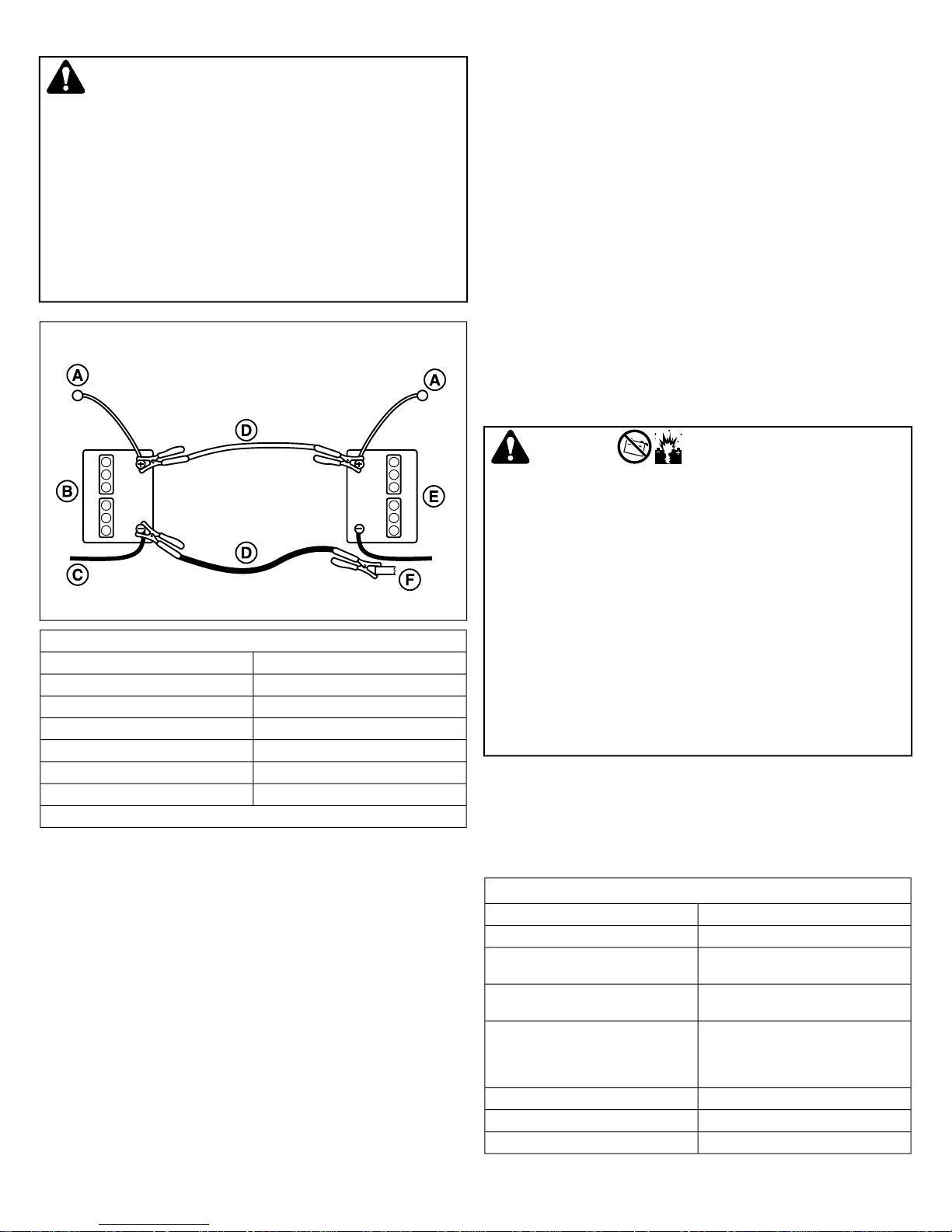
WARNING
For your personal safety, use extreme care when jump
starting. Never expose battery to open flame or electric spark
– battery action generates hydrogen gas which is flammable
and explosive. Do not allow battery acid to contact skin, eyes,
fabrics, or painted surfaces. Batteries contain a sulfuric acid
solution which can cause serious personal injury or property
damage.
To avoid engine damage, do not disconnect battery while
engine is running. Be sure terminal connections are tight
before starting.
58
8. Start the engine of the vehicle with the booster battery. Wait
a few minutes, then attempt to start the engine of the vehicle
with the discharged battery.
9. If the vehicle does not start after cranking for ten (10)
seconds, STOP PROCEDURE. More than ten (10) seconds
seldom starts the engine unless some mechanical
adjustment is made. Allow a sixty (60) second cool down
period between starting attempts. Failure to follow these
guidelines can burn out starter motor.
10. After starting, allow the engine to return to idle speed.
Remove the cable connection at the engine or frame. Then
remove the other end of the same cable from the booster
battery.
11. Remove the other cable by disconnecting at the discharged
battery first and then disconnect the opposite end from the
booster battery.
12. Discard the damp cloths that were placed over the battery
vent caps.
WARNING
Any procedure other than the preceding could result in:
(a) personal injury caused by electrolyte squirting out the
battery vents,
This hook-up is for negative grounded vehicles.
DescriptionCallout
To Starter SwitchA
Starting Vehicle BatteryB
To GroundC
Jumper CableD
Discharged Vehicle BatteryE
Engine BlockF
Make sure vehicles do not touch.
1. Both batteries must be of the same voltage.
2. Position the vehicle with the booster battery adjacent to the
vehicle with the discharged battery so that booster cables
can be connected easily to the batteries in both vehicles.
Make certain vehicles do not touch each other.
3. Wear safety glasses and shield eyes and face from batteries
at all times. Be sure vent caps are tight. Place damp cloth
over vent caps on both batteries.
4. Connect positive (+) cable to positive post of discharged
battery (wired to starter or solenoid).
5. Connect the other end of same cable to same post marked
positive (+) on booster battery.
6. Connect the second cable negative (-) to other post of
booster battery.
7. Make final connection on engine block of stalled vehicle
away from battery. Do not lean over batteries.
(b) personal injury or property damage due to battery
explosion,
(c) damage to the charging system of the booster vehicle or
of the immobilized vehicle.
Do not attempt to jump start a vehicle having a frozen battery
because the battery may rupture or explode. If a frozen battery
is suspected, examine all fill vents on the battery. If ice can
be seen or if the electrolyte fluid cannot be seen, do not
attempt to start with jumper cables as long as the battery
remains frozen.
Troubleshooting
Troubleshooting Charts
Troubleshooting the Zero-Turn Rider
Problem: Engine will not turnover or start.
RemedyCause
Engage parking brake.Parking brake not engaged.
position.
Out of fuel.
Engine flooded.
Place in OFF position.PTO (electric clutch) switch in ON
If engine is hot, allow it to cool, then
refill the fuel tank.
Carburated Models: Move choke
control to closed position. Fuel
Injected Models: See authorized
dealer.
Replace fuse.Fuse blown.
Clean the battery terminals.Battery terminals require cleaning.
Recharge or replaceBattery discharged or dead.
38 ferrisindustries.com
Page 39
Problem: Engine will not turnover or start.
Wiring loose or broken.
Safety interlock switch faulty
Spark plug(s) faulty, fouled or
incorrectly gapped.
Problem: Engine starts hard or runs poorly.
Fuel mixture too rich.
Spark plug(s) faulty, fouled or
incorrectly gapped.
Problem: Engine knocks.
Problem: Excessive oil consumption.
Problem: Engine exhaust is black.
position.
Visually check wiring & replace broken
or frayed wires. Tighten loose
connections.
See authorized service dealer.Solenoid or starter motor faulty.
Replace as needed. See authorized
service dealer.
Clean and gap or replace. See engine
manual.
Drain fuel and replace with fresh fuel.Water in fuel.
Drain fuel and replace with fresh fuel.Gas is old or stale.
See authorized service dealer.Malfunction in fuel injection system.
RemedyCause
1.) Clean air filter. 2.) Carburated
Models: Check choke adjustment.
Fuel Injected Models: See authorized
dealer.
Clean and gap or replace. See engine
manual.
RemedyCause
Check / Add oil as required.Low oil level.
See engine manual.Using wrong grade oil.
RemedyCause
See engine manual.Using wrong weight oil.
Drain excess oilToo much oil in crankcase.
RemedyCause
Replace air filter. See engine manual.Dirty air filter.
Move choke control to open position.Engine choke control is in closed
Problem: Unit drive belt slips.
Replace belt.Belt stretched or worn
Problem: Brake will not hold.
RemedyCause
See Parking Brake Adjustment.Brake is incorrectly adjusted.
Replace with new pads.Brake pads worn.
Problem: Unit steers or handles poorly.
RemedyCause
Steering linkage is loose.
Check and tighten any loose
connections.
See Checking Tire PressuresImproper tire inflation
Troubleshooting the Mower
Problem: Mower will not raise.
RemedyCause
damaged.
See authorized dealer.Lift linkage not properly attached or
Problem: Engine stalls easily with mower engaged.
RemedyCause
Set to full throttle.Engine speed to slow.
Decrease ground speed.Ground speed too fast.
Increase the cutting height.Cutting height set too low.
Discharge chute jamming with cut
grass.
Cut grass with discharge pointing
towards previously cut area.
Problem: Excessive mower vibration.
RemedyCause
Tighten to 70 ft.lbs (94 Nm)Blade mounting bolts are loose.
bent.
Mower blades are out of balance.
Check and replace as necessary.Mower blades, arbors, or pulleys are
Remove, sharpen, and balance blades.
See Servicing the Mower Blades.
Reinstall belt correctly.Belt installed incorrectly.
Problem: Malfunction Indicator Lamp (M.I.L.) is flashing
(Fuel Injected Models only).
RemedyCause
See your authorized service dealer.Problem with the fuel injection system.
Problem: Engine runs but mower will not drive.
RemedyCause
"bypass" position.
Belt is broken.
Turn valves to "run" position.Transmission release valve(s) in
See
Transmission Drive Belt
Replacement
See problem and cause below.Drive belt slips.
See authorized service dealer.Brake is not fully released.
.
Problem: Unit drive belt slips.
RemedyCause
Clean as required.Pulleys or belt greasy or oily.
Tension too loose
Adjust spring tension. See
Transmission Drive Belt Replacement
Problem: Excessive belt wear or breakage.
Problem: Drive belt slips or fails to drive.
Battery voltage too low.
.
RemedyCause
Repair or replace.Bent or rough pulleys.
Replace with correct belt.Using incorrect belt.
Adjust to correct tension.Incorrect belt tension.
RemedyCause
Adjust to correct tension.Incorrect belt tension.
Replace with new belt.Drive belt is broken.
Problem: Mower does not engage.
RemedyCause
Locate & repair damaged wire.Electrical wiring damage.
Recharge battery and check alternator.
See Battery Service.
39
Page 40
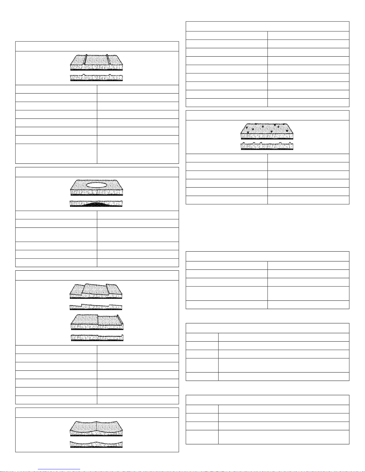
Troubleshooting Common Cutting
Problems
Problem: Streaking
RemedyCause
Sharpen your blades.Blades are not sharp.
Replace your blades.Blades are worn down too far.
Always mow at full throttle.Engine speed is too slow.
Slow down.Ground speed is too fast.
Clean out the mower.Deck is plugged with grass.
Overlap your cutting rowsNot overlapping cutting rows enough.
Not overlapping enough when turning.
Problem: Scalping
When turning your effective cutting
width decreases–overlap more when
turning.
Problem: Uneven Cutting
RemedyCause
Level the deck correctly.Deck is not leveled correctly.
Sharpen or replace the blades.Blades are dull or worn.
Replace the blades.Blades are damaged.
Clean out the deck.Deck is clogged with grass clippings.
Repair or replace the deck.Deck shell is damaged.
Repair or replace the spindle.Mower spindle is bent or loose.
Reinstall the blades correctly.Blades are installed incorrectly.
Check and inflate the tires.Tires are not properly inflated.
Problem: Stingers
RemedyCause
Sharpen your blades.Blades are not sharp or nicked.
Replace your blades.Blades are worn down too far.
Always mow at full throttle.Engine speed is too slow.
Slow down.Ground speed is too fast.
Clean out the mower.Deck is plugged with grass.
low.
RemedyCause
Roll or level the lawn.Lawn is uneven or bumpy.
Raise the cutting height.Mower deck cutting height is set too
Slow down.Ground speed is too fast.
Correctly level the deck.Deck is not leveled correctly.
Check and inflate the tires.Tire pressure is low or uneven.
Problem: Stepped Cutting
RemedyCause
Level the deck correctly.Deck is not leveled correctly.
Check and inflate the tires.Tires are not properly inflated.
Replace the blades.Blades are damaged.
Repair or replace the deck.Deck shell is damaged.
Repair or replace the spindle.Mower spindle is bent or loose.
Reinstall the blades correctly.Blades are installed incorrectly.
Problem: Uneven Cutting
Specifications
ENGINE
Fits models: 5901301 & 5901307
25.5 Gross HP† Kawasaki
Electrical System
Fits models: 5901300 & 5901302
26 Gross HP* Briggs & Stratton Vanguard
Briggs & StrattonMake
49R977-9322-96Model
49.42 Cu. in (810 cc)Displacement
12 Volt, 16 amp. Alternator, Battery: 340 ccaElectrical
System
2.1 qt. (2.0 L) w/ filterOil Capacity
Fits models: 5901333
28 Gross HP* Briggs & Stratton EFI
Briggs & StrattonMake
49E877-0001-G1Model
49.42 Cu. in (810 cc)Displacement
12 Volt, 20 amp. Alternator, Battery: 340 ccaElectrical
System
KawasakiMake
FX801VModel
52.0 Cu. in (852 cc)Displacement
12 volt, 15 amp charging coil; Battery:
340 cca
1.9 US qt. (1.8 L) w/ filterOil Capacity
40 ferrisindustries.com
Page 41
28 Gross HP* Briggs & Stratton EFI
2.1 qt. (2.0 L) w/ filterOil Capacity
Fits models: 5901304
29/27 Gross HP¹ Kohler EFI
KohlerMake
ECV749-3022Model
45.6 Cu. in (747 cc)Displacement
Electrical System
12 volt, 20 amp. Alternator; Battery:
340 cca
2.0 US qt. (1.9 L) w/ filterOil Capacity
Fits models: 5901303
32 Gross HP* Briggs & Stratton Vanguard
Briggs & StrattonMake
543777-1120-E1Model
54.68 Cu. in (896 cc)Displacement
Electrical System
12 volt, 20 amp alternator; Battery: 340
cca
2.4 US qt. (2.3 L) w/ filterOil Capacity
†Power Ratings: All power levels are stated gross horsepower
per SAE J2723 as rated by Kawasaki and tested per the SAE
J1995 test standard. The gross power curves and more
information can be viewed at www.kawasaki-criticalpower.com.
*Power Ratings: The gross power rating for individual gasoline
engine models is labeled in accordance with SAE (Society of
Automotive Engineers) code J1940 Small Engine Power &
Torque Rating Procedure, and is rated in accordance with SAE
J1995. Torque values are derived at 2600 RPM for those
engines with “rpm” called out on the label and 3060 RPM for all
others; horsepower values are derived at 3600 RPM. The gross
power curves can be viewed at
www.BRIGGSandSTRATTON.COM. Net power values are
taken with exhaust and air cleaner installed whereas gross
power values are collected without these attachments. Actual
gross engine power will be higher than net engine power and
is affected by, among other things, ambient operating conditions
and engine-to-engine variability. Given the wide array of
products on which engines are placed, the gasoline engine may
not develop the rated gross power when used in a given piece
of power equipment. This difference is due to a variety of factors
including, but not limited to, the variety of engine components
(air cleaner, exhaust, charging, cooling, carburetor, fuel pump,
etc.), application limitations, ambient operating conditions
(temperature, humidity, altitude), and engine-to-engine
variability. Due to manufacturing and capacity limitations, Briggs
& Stratton may substitute an engine of higher rated power for
this engine.
¹Power Ratings: Actual sustained equipment horsepower will
likely be lower due to operating limitations and environmental
factors.
CHASSIS
Capacity
Rear Wheels
with 52" Decks)
with 61" Decks)
Front Wheels
with 52" Decks)
with 61" Decks)
11 gallons (41.6 L) totalFuel Tank
23 x 9.5 - 12Tire Size (Models
23 X 10.5 - 12Tire Size (Models
15 psi (1.03 bar)Inflation Pressure
13 x 5.0 - 6Tire Size (Models
13 X 6.5 - 6Tire Size (Models
25 psi (1.72 bar)Inflation Pressure
TRANSMISSIONS
52" Models
1015-1024LLH
1015-1024RRH
61" Models
1015-1057LLH
1015-1057RRH
ZT5400 TransaxlesType
Fluid
Speeds
SAE 20W-50 motor oilHydraulic
0-10 MPH (0-16.09 km/h)Forward
0-5 MPH (0-8.05 km/h)Reverse
DIMENSIONS
Models with 61" Mower DecksModels with 52" Mower Decks
Length
Overall
Width
(apx.):
57" (145 cm) with discharge
chute up
67" (170 cm) with discharge
chute down
82.5" (210 cm)Overall
61-1/2" (156 cm) with discharge
chute up
78" (198 cm) with discharge
chute down
71" (180 cm)Height
1295 lbs (587 kg)1223 lbs (555 kg)Weight
Warranty
Warranty Statement
BRIGGS & STRATTON WARRANTY POLICY (January 2014)
LIMITED WARRANTY
Briggs & Stratton warrants that, during the warranty period
specified below, it will repair or replace, free of charge, any part
that is defective in material or workmanship or both.
Transportation charges on product submitted for repair or
replacement under this warranty must be borne by purchaser.
This warranty is effective for and is subject to the time periods
and conditions stated below. For warranty service, find the
nearest Authorized Service Dealer in our dealer locator map at
41
Page 42

ferrisindustries.com
.The purchaser must contact the Authorized
Service Dealer, and then make the product available to the
Authorized Service Dealer for inspection and testing.
There is no other express warranty. Implied warranties,
including those of merchantability and fitness for a
particular purpose, are limited to the warranty period listed
below, or to the extent permitted by law . Liability for
incidental or consequential damages are excluded to the
extent exclusion is permitted by law. Some states or countries
do not allow limitations on how long an implied warranty lasts,
and some states or countries do not allow the exclusion or
limitation of incidental or consequential damages, so the above
limitation and exclusion may not apply to you. This warranty
gives you specific legal rights and you may also have other
rights which vary from state to state or country to country.**
WARRANTY PERIOD
Covered Parts
Riding mowers - except
as noted below +
Walk mowers - except as
noted below +
(over 30 inches of cutting
width)
+Coil over shocks and all
suspension-related
components
Pads, Hoses, Battery,
Blades
+Engine*
Period
500 hours, which occurs
first.
Unlimited hours during
the first 2 years (24
months)
unlimited hours
unlimited hours
See Engine Operator's
Manual
Rental Warranty PeriodStandard Warranty
90 days4 years (48 months) or
90 days2 years (24 months)
90 days4 years (48 months)
90 days90 days+Belts, Tires, Brake
90 days1 year+Attachments
See Engine Operator's
Manual
* Emissions-related components are covered by the Emissions
Warranty Statement
** In Australia - Our goods come with guarantees that cannot
be excluded under the Australian Consumer Law. You are
entitled to a replacement or refund for a major failure and for
compensation for any other reasonably foreseeable loss or
damage. You are also entitled to have the goods repaired or
replaced if the goods fail to be of acceptable quality and the
failure does not amount to a major failure. For warranty service,
find the nearest Authorized Service Dealer in our dealer locator
map at FERRISINDUSTRIES.COM/AU, or by calling 1300 274
447, or by emailing or writing to
[email protected], Briggs & Stratton
Australia Pty Ltd, 1 Moorebank Avenue, NSW, Australia, 2170.
The warranty period begins on the date of purchase by the first
retail or commercial customer.
Save your proof of purchase receipt. If you do not provide proof
of the initial purchase date at the time warranty service is
requested, the manufacturing date of the product will be used
to determine the warranty period. Product registration is not
required to obtain warranty service on Briggs & Stratton
products.
ABOUT YOUR WARRANTY
Warranty service is available only through
Ferris
Authorized
Service Dealers. This warranty only covers defects in materials
or workmanship. It does not cover damage caused by improper
use or abuse, improper maintenance or repair, normal wear
and tear, or stale or unapproved fuel.
Improper Use and Abuse - The proper, intended use of this
product is described in the Operator's Manual. Using the product
in a way not described in the Operator's Manual or using the
product after it has been damaged will not be covered under
this warranty. Warranty coverage will also not be provided if the
serial number on the product has been removed or the product
has been altered or modified in any way, or if the product has
evidence of abuse such as impact damage, or water/chemical
corrosion damage.
Improper Maintenance or Repair - This product must be
maintained according to the procedures and schedules provided
in the Operator's Manual, and serviced or repaired using genuine
Briggs & Stratton parts or equivalent. Damage caused by lack
of maintenance or use of non-original or non-equivalent parts
is not covered by warranty.
Normal Wear and Tear - Like all mechanical devices, the unit
is subject to wear even when properly maintained. This warranty
does not cover replacement or repairs when normal use has
exhausted the life of a part or the equipment. Except as noted
in the warranty period, maintenance and wear items such as
filters, belts, cutting blades, and brake pads (except engine
brake pads) are not covered by warranty due to wear
characteristics alone, unless the cause is due to defects in
material or workmanship.
Stale or Unapproved Fuel - In order to function correctly, this
product requires fresh fuel that conforms to the criteria specified
in the Operator's Manual. Engine or equipment damage caused
by stale fuel or the use of unapproved fuels (such as E15 or
E85 ethanol blends) is not covered by warranty.
Other Exclusions - This warranty excludes damage due to
accident, abuse, modifications, alterations, improper servicing,
freezing or chemical deterioration. Attachments or accessories
that were not originally packaged with the product are also
excluded. This warranty does not include used, reconditioned,
second-hand, or demonstration equipment or engines. This
warranty also excludes failures due to acts of God and other
force majeure events beyond the manufacturer's control.
To ensure prompt and complete warranty coverage, register
your product at the website shown above or at
www.onlineproductregistration.com, or mail the completed
registration card (if provided), or call 1-800-743-4115 (in USA).
42 ferrisindustries.com
Page 43

Notes
Page 44

 Loading...