

Ferrari electronic OfficeMaster Gate User Manual

OfficeMaster Gate – Ferrari electronic AG
OfficeMaster Gate
ISDN Controller
Mediagateway
Survivable Branch Appliance

II
www.ferrari-electronic.com
Copyright and Legal Notice OfceMaster is Copyright © 2011 by Ferrari electronic AG. All rights reserved. No part of this document may be copied, in
any way, without written approval from Ferrari electronic AG. All trademarks mentioned are registered trademarks of the particular trademark holder. The in-
formation contained in this document has been gathered with greatest care. However the possibility of incorrect details cannot be completely excluded. Ferrari
electronic AG does not accept liability for any errors and their consequences. Please email comments and suggestions to:
dokumentation@ofcemaster.de
Note!▼ Help for technical problems can be found on our Webportal:
www.ferrari-electronic.de/de/service/support/supportanforderung.html
Publisher
Ferrari electronic AG
Ruhlsdorfer Str. 138
14513 Teltow (bei Berlin)
March 2013
www.ferrari-electronic.de
Telephone
+49 (3328) 455 90
Fax
+49 (3328) 455 960
E-Mail
info@ferrari-electronic.de
Authors
Johann Deutinger
Nils Küchler
Chris Helbing
Redaktion/Layout
Chris Helbing
Veröffentlichung
28.10.2013, 8. Auage

III
www.ferrari-electronic.com
Foreword
Thank you for your trust in products of Ferrari electronic AG and your decision to use OfceMaster.
Ferrari electronic is a leading German manufacturer of hardware and software for unied communications. The
OfceMaster range of products enhances all popular e-mail and application systems with functions for fax, SMS
and voicemail. The hardware seamlessly connects a company‘s telecommunications infrastructure with the existing
information technology. Customers benet from greater efciency and streamlined business processes.
We hope the product satises your companies needs entirely. In case of questions of suggestions please email:
info@ferrari-electronic.de

IV
www.ferrari-electronic.com
Inhalt
1. Product description ......................................................................................................... 1
1.1 OfceMaster Gate: ISDN-Controller and Media gateway....................................................................3
1.1.1 OfceMaster Gate stainless steel box for Basic Rate Interface (BRI) ........................................................3
1.1.2 OfceMaster Gate for Primary Rate Interface (PRI) ................................................................................... 4
1.1.3 OfceMaster Gate UC .................................................................................................................................4
1.2 OfceMaster Survivable Branch Appliance (SBA) ..............................................................................5
1.1 Functionality and Connection ...............................................................................................................6
1.2.1 One product – multiple possible applications .............................................................................................. 6
1.2.2 Connection to Exchange 2007/2010/2013 UM ...........................................................................................6
1.2.3 Use as media gateway for Lync Server 2013/2010 ..................................................................................... 7
2. Installation ....................................................................................................................... 9
2.1 ISDN Port ..............................................................................................................................................9
2.2 Network Integration ..............................................................................................................................9
2.3 Installation of the Survivable Branch Appliance ................................................................................10
2.3.1 Rear view of server machine .....................................................................................................................10
2.3.2 Anatomy of the Media Gateway Board (MGB) ........................................................................................ 11
2.3.3 Analog Card – 4 Port (FXS) ......................................................................................................................12
2.3.4 ISDN and Analog Interfaces ...................................................................................................................... 12
2.4 Recovery .............................................................................................................................................13
2.4.1 Survivable Branch Appliance ....................................................................................................................13
2.5 Stainless steel box - Restore to factory settings ..................................................................................15
3. Conguration................................................................................................................. 17
3.1 OfceMaster Gate Basic Settings .......................................................................................................17
3.1.1 Connecting to OfceMaster Gate ..............................................................................................................18
3.1.2 Network conguration ...............................................................................................................................18
3.1.3 „Common“ ................................................................................................................................................. 20
3.1.4 Calls from ISDN ........................................................................................................................................24
3.1.5 Calls to ISDN ............................................................................................................................................ 28
3.1.6 Testing routing rules ..................................................................................................................................29
3.2 Conguration and Activation of OfceMaster SBA ...........................................................................30
3.2.1 Preparations in the central computing center............................................................................................. 31
3.2.2 Installation OfceMaster SBA ...................................................................................................................31
3.2.3 Media Gateway Conguration ................................................................................................................... 36

V
www.ferrari-electronic.com
3.2.4 Testing Media Gateway Routing for OfceMaster SBA ........................................................................... 38
3.2.5 Display Event Logs and Syslog File .......................................................................................................... 39
3.2.6 System Status ............................................................................................................................................. 39
3.3 OfceMaster Gate and Lync Server 2010 ...........................................................................................40
3.3.1 Connection via TCP/RTP (not encrypted) .................................................................................................40
3.3.2 Conguring TLS/SRTP ..............................................................................................................................47
3.4 OfceMaster Gate and Exchange Unied Messaging ........................................................................51
3.4.1 Receiving Fax with Microsoft Exchange 2010 ........................................................................................51
3.5 Drop & Insert – OMG between Trunk and PBX ................................................................................59
3.5.1 Inbound routing, Trunk->OMG->PBX ...................................................................................................... 60
3.5.2 Outbound routing, PBX->OMG->Trunk ................................................................................................... 62
4. Advanced Conguration ............................................................................................... 65
4.1 Sign in at a SIP-Trunk .........................................................................................................................65
4.2 Settings for OfceMaster SIP2Lync ...................................................................................................66
4.3 VoIP Parameter ....................................................................................................................................67
4.4 ISDN Parameter ..................................................................................................................................70
4.5 ISDN-SIP Mapping .............................................................................................................................72
4.6 Music on hold ......................................................................................................................................73
5. Web Interface ................................................................................................................ 75
5.1 Overview - Home ................................................................................................................................75
5.2 System Health ....................................................................................................................................76
5.3 System Info .........................................................................................................................................79
5.4 Exchange Unied Messaging ..............................................................................................................80
5.5 Test calls ..............................................................................................................................................80
5.6 Line Status ...........................................................................................................................................81
5.7 System Traces .....................................................................................................................................82
6. Worth knowing .............................................................................................................. 85
6.1 Ofine Conguration ..........................................................................................................................85
6.2 Logging/Syslog ...................................................................................................................................85
6.3 Saving the conguration .....................................................................................................................86
6.4 Firmware update OfceMaster Gate ...................................................................................................86
6.5 Changing Password .............................................................................................................................87

VI
www.ferrari-electronic.com
6.6 License management ...........................................................................................................................87
6.6.1 General settings .........................................................................................................................................87
6.6.2 Advanced settings ...................................................................................................................................... 89
Appendix A: List of Abbreviations .................................................................................... ii
Appendix B: Echo Canceling ............................................................................................ iii
Appendix C: Telephone number basics ............................................................................ iv
C.1: Rule based treatment of inbound calls ...............................................................................................iv
C.2: Regular expressions .............................................................................................................................v
C.3: Conguration examples .................................................................................................................... vii

1
www.ferrari-electronic.com
Product description
1. Product description
OfceMaster Gate is a family of hardware controllers designed for Unied Communications applications. More
than 20 years of work experience by Ferrari electronic have own into the construction. Hereby the acquired skills
in the elds of active Fax/ISDN cards and networking Fax/SMS/voice mail solutions played a major part. The rm-
ware of the intelligent controllers has since then been signicantly extended and improved. Versatile scenarios are
supported:
Fax, SMS and voice mail services are supported for different operating systems when combined with the Unied
Messaging Software OfceMaster.
OfceMaster Gate can be used as a phone gateway to link ISDN-Private Branch Exchanges (PBX) or Trunks to
Microsoft Exchange Server 2007/2010/2013 UM, Ofce Communications Server 2007 and Microsoft Lync Server
2010/2013 in order to integrate their Unied Communications functionalities.
Those functionalities can be combined as well.
OfceMaster Gate is connected to the voice network via ISDN Basic Rate Interface (BRI) respectively ISDN
Primary Rate Interface (PRI) ports. An overview on all possible combinations can be found in the chart below.
OfceMaster Gate stainless steel box is always usable as Unied Messaging Controller or Gateway. There also is
a cheaper version of the larger PRI edition, solely for telephony (“UC”-edition). If need be those can be enhanced to
full functionality afterwards by purchasing the required licenses. All versions of the product can be set up at ISDN
main ports as well as on phone PBX’s.
By purchasing licenses OfceMaster Gate can be extended by multiple ports and functionalities.

2
www.ferrari-electronic.com
Product description
Table 1.1: Available versions of OfceMaster Gate, as of 5.3.2013
Article
(Article number)
Ports
Notes
physically pos-
sible
licensed expandable to
ISDN Gateways for OfceMaster Suite incl. Media Gateway Funktion
OfceMaster Gate stainless steel box (BRI)
OfceMaster Gate
(20683)
4 x BRI 1 x BRI (2 channels)
• 1 to 3 x BRI (20823)
• 5 SIP channels (20816)*
Stainless steel box with rmware
OfceMaster Gate
(20693)
4 x BRI 4 x BRI (8 channels) 5 SIP channels (20816)*
Stainless steel box with rmware
OfceMaster Gate 19“ for ISDN Primary Rate Interface (PRI)
(Number of available channels with one PRI depends on the protocol used: E1 = 30 channels, T1 = 24 channels)
OfceMaster Gate
(20603)
2 x PRI
1 x PRI (30 channels)
• 1 x PRI (20803)
• 5 SIP channels (20816)*
• 19“ server with rmware
• Software RAID
OfceMaster Gate
(20613)
2 x PRI
2 x PRI (60 channels)
5 SIP channels (20816)*
• 19“ server with rmware
• Software RAID
Media Gateways for Microsoft Lync Server 2013/2010 and Microsoft Exchange Unied Messaging
Passive PCIe low-prole card
Additional UM extensions are required in order to connect to OfcMaster Suite!
OfceMaster Gate, passive
PCIe card (22104)
4 x PRI (60) channels
none!
• 1 to 4 x PRI (22803)
• 4 x FXS (21273)
• analog card (22873)
• 5 SIP channels (20816)*
• low-prole PCIe card
• requires rmware on the server system
OfceMaster Gate UC
(22114)
4 x PRI (60) channels
none!
• 1 to 4 x PRI (22803)
• 4 x FXS (21273)
• analog card (22873)
• 5 SIP channels (20816)*
• 19“ server with rmware
• passive PCIe card
• Software RAID
Active PCIe card
Additional UM extensions are required in order to connect to OfcMaster Suite!
OfceMaster Gate active
PCIe card (22304)
• 4 x BRI (8 channels)
• 2 x PRI (60 channels)
none!
• 1 to 2 x PRI (22803)
• 4 x BRI (22813)
• 4 x FXS (21273)
• analog card (22873)
• 5 SIP channels (20816)*
• active PCIe card
• embedded System, complete
Gateway
OfceMaster SBA (22314)
• 4 x BRI (8 channels)
• 2 x PRI (60 channels)
• 4 x FXS (4 channels)
none!
• 1 to 2 x PRI (22803)
• 4 x BRI (22813)
• 4 x FXS (21273)
• 5 SIP channels (20816)*
• Tower with Windows
• active PCIe card
• Software RAID
OfceMaster SBA (22323)
• 4 x BRI (8 channels)
• 2 x PRI (60 channels)
• 4 x FXS (4 channels)
none!
• 1 to 2 x PRI (22803)
• 4 x BRI (22813)
• 4 x FXS (21273)
• 5 SIP channels (20816)*
• 19“ server with Windows
• active PCIe card
• redundant power supply
• Hardware RAID
*The maximum amount of SIP channels depends on the performance of the used computer hardware and the re-
quested range of functions. Please contact Ferrari electronic AG about this.
3
www.ferrari-electronic.com
Product description
1.1 OfficeMaster Gate: ISDN-Controller and Media gateway
Through the various scenarios of use different versions of OfceMaster Gate were developed. In this part Of-
ceMaster Gate products are described that function as independent Gateways respectively Controllers. (Apart from
that there are versions of boards that are described later on.)
No additional software needs to be loaded into the box. All of the linux based rmware is placed in the ash drive
and loaded into the RAM for execution when booted.
Operated on a PBX (resp. Point-to-Point protocol), Ofce Master Gate acts similar to a PBX, meaning it sup-
ports direct inward addressing and allows automatic assigning of calls (fax, SMS, voice mail and phone) depending
on different dial through numbers.
OfceMaster Gate complies with the specications dened by the ITU for fax group 3. Apart from the compul-
sory transmission with 4800 and 2400 bps, 9600 resp. 7200 and 14400 resp. 12000 bps are possible too.
For fax transmission dened one and two dimensional modes of compression MH, MR and MMR as well as the
error correction mode (ECM) are supported.
Alternatively or simultaneously OfceMaster Gate can be used as a media gateway for Microsoft Exchange UM,
OCS 2007 (incl. R2) as well as for Microsoft Lync Server 2010.
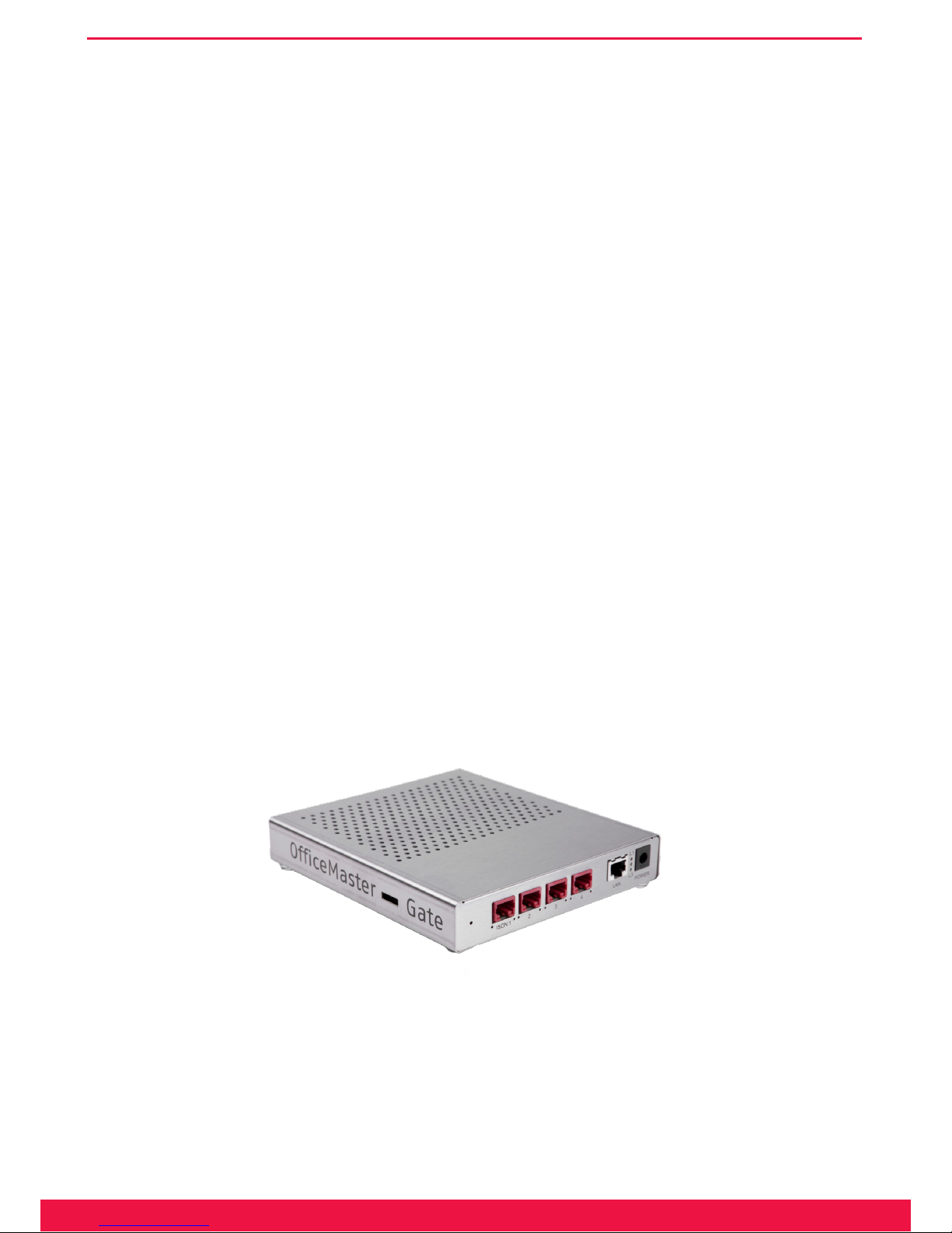
1.1.1 OfficeMaster Gate stainless steel box for Basic Rate Interface (BRI)
The BRI editions of OfceMaster Gate run a powerful 32-bit microprocessor. No additional software needs to be
loaded into the box. All of the linux based rmware is placed in the ash drive and loaded into the RAM for execu-
tion when booted. Because of the autonomy of the system, the UM server is supported by the controller, keeping
the strain to a minimum. No settings via jumper are needed for the hardware, making installing, implementing and
if needed replacing very simple
Image 1.1: OfceMaster Gate BRI stainless steel box
4
www.ferrari-electronic.com
Product description
OfceMaster Gate for BRI can use both channels of a line simultaneously. The controller supports Euro-ISDN
(EDSS1) and works on a multiple device line as well as on the system line. OfceMaster Gate is also usable for
subsystems and supports some performance characteristics of the TK system protocol QSIG (Q-Interface Signaling
Protocol).
OfceMaster Gate can either be plugged in with the included power adapter or, if supported in the network ac-
cording to 802.3af, be supplied via Power over Ethernet (PoE).
Note!▼ Are both power supplies enabled, the power adapter is used. Hereby it is strongly
recommended to first plug in the mains power supply and after that the Ethernet connection. A switch of power supplies is to be avoided while booting.
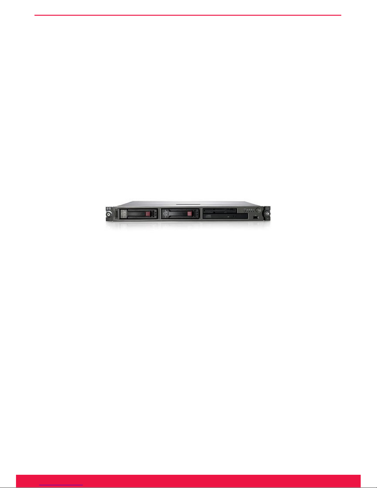
1.1.2 OfficeMaster Gate for Primary Rate Interface (PRI)
OfceMaster Gate for PRI is shipped in a 19“ case. This case holds a PC Mainboard. The PRI adapter is included
in form of a PCIe board.
Image 1.2: OfceMaster Gate 19“ version
OfceMaster Gate for PRI (19“) can use all 30 to 60 (respectively 120) channels of a line simultaneously. The
controller supports Euro-ISDN (EDSS1) as well as important features of the TK system protocol QSIG (Q-Interface
Signaling Protocol).
1.1.3 OfficeMaster Gate UC
For the use as a Media gateway for Microsoft Exchange 2007/2010/2013, Microsoft Ofce Communications
Server 2007 R2 and Microsoft Lync Server 2010/2013, specic versions of OfceMaster Gate are available, which
are not supported on delivery.
By subsequently adding additional licences, channels for the selection of OfceMaster Software for fax, voice
mail and SMS can be enabled step by step.
5
www.ferrari-electronic.com
Product description
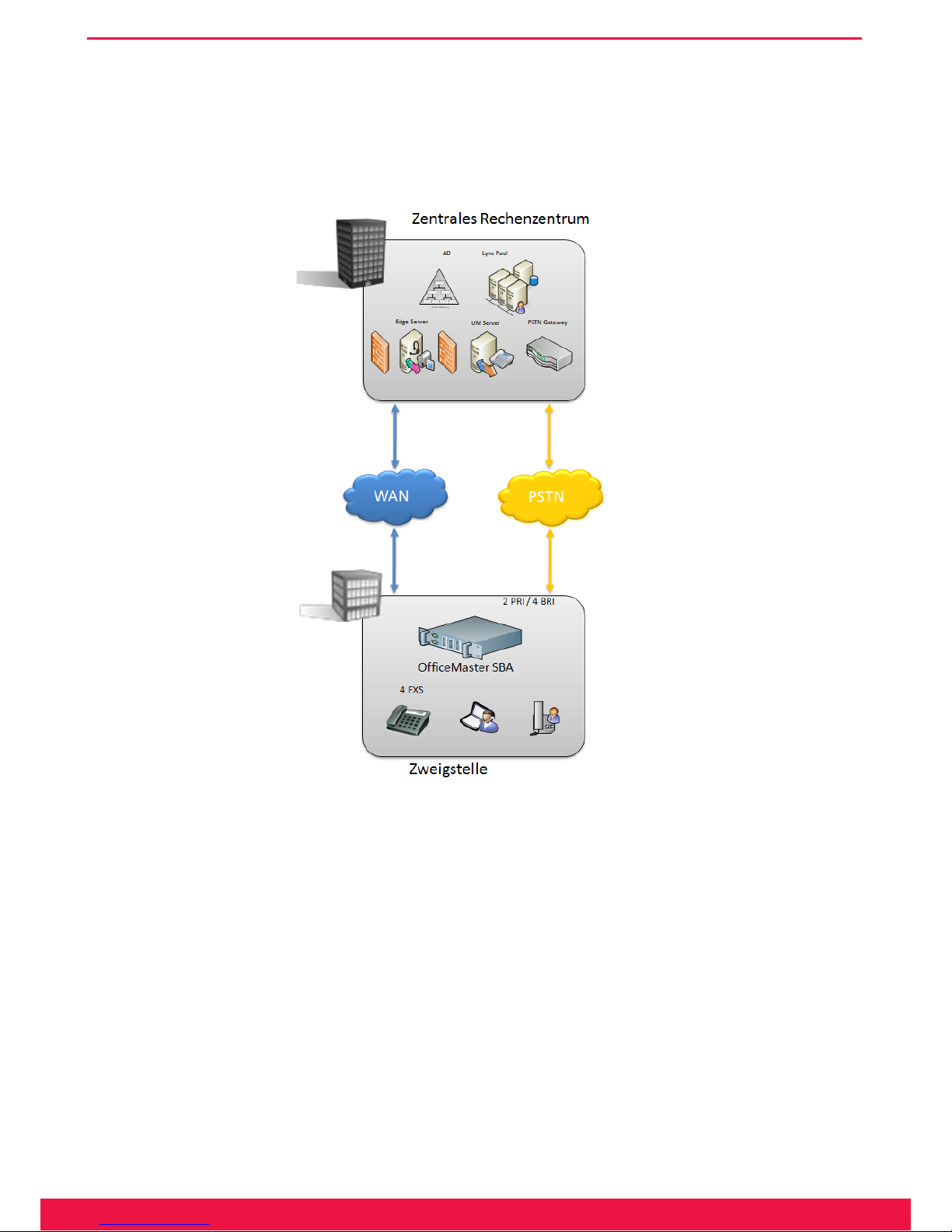
1.2 OfficeMaster Survivable Branch Appliance (SBA)
With Microsoft Ofce Communications Server (2007/2007 R2) it was for the rst time possible to use a central
installed OCS at a remote branch. This cost-efcient solution had the drawback that in case of a WAN failure the
whole telephony at that specic branch would fail.
Image 1.3: Solution scenario with OfceMaster SBA
Microsoft Lync Server 2010 was the rst version that supported remote site telephony even on WAN outages.
Microsoft has dened an appliance type of products containing all functions needed for telephony in a branch of-
ces; therefore called “Survivable Branch Appliance” (SBA). The same holds true for the new Lync Server 2013
which also offers a compatible SBA product.
„OfceMaster SBA“ is based on high quality industry grade server hardware which runs Windows Server 2008
R2 together with Microsoft branch ofce components like Registrar and Mediation Server.
A separate PCI-Express card contains the complete media gateway which supports different types of ISDN con-
nections – four basic rate interfaces (BRI) supporting 8 ports and up to 60 channels of E1/T1 primary rate (PRI)
connections. Four analog FXS ports are available through an additional low prole PCIe card. If more ports are
needed, separate external devices can be added. In addition, support for SIP trunks and legacy telephony devices are
available as well. The gateway board is recognized by the hosting server machine as a standard network interface
card – all gateway functions are completely off-loaded from the main CPU.

6
www.ferrari-electronic.com
Product description
The same hardware can also be used as a Basic Hybrid Gateway for Microsoft Ofce Communications Server
2007 R2 which can be upgraded to a Survivable Branch Appliance later.
1.1 Functionality and Connection
1.2.1 One product – multiple possible applications
For the use as gateway for Exchange 2007/2010/2013 / Ofce Communications Server 2007 (OCS/OCS R2) /
Microsoft Lync Server 2010 as well as when used as Unied Messaging Controller, it is necessary to obtain certain
information about the caller. The called number and potential carried out call forwarding need to be evaluated in
order to nd the appropriate way of processing the call.
When used as Gateway and Unied Messaging Controller at the same time, it is to be decided whether an incom-
ing call is meant for Exchange, OCS, Lync Server or the OfceMaster Messaging Server. This calling information
is provided on each call via the ISDN-D-Channel-Protocol. Depending on the different telephone system, the depic-
tion can however vary. To ensure uniform depiction for the further use, an extremely capable call number analysis
and call number correction has been integrated into OfceMaster Gate.
Inherently, OfceMaster Gate is installed on a telephone system or a trunk line via ISDN and is able to process
incoming calls. For those calls OfceMaster Gate decides whether or not to take the call, upon the routing (by which
instance, for example Exchange 2007/2010, OCS, Lync Server or OfceMaster, the call is to be handled) and upon
the replacing or respectively modifying of call information (which call information does the processing instance
expect at what point).
Through additional functions provided by OfceMaster Gate for Microsoft UM/UC solutions (Exchange, OCS,
Lync) and through the double functionality as controller for the Unied Messaging System OfceMaster, relatively
complex settings for calling numbers can be required. The conguration of usual cases of application is therefore
possible via a very simple dialog, while more complex settings can be made via exible rule-table in the advanced
mode. It is possible to switch between advanced and simplied mode. In the simplied mode created congurations
are internally converted into rules and can be looked at in the advanced mode.
1.2.2 Connection to Exchange 2007/2010/2013 UM
In the following, the processing of incoming calls in Exchange UM is described. The phone number of a par-
ticipant, who has been activated for Exchange Unied Messaging, is saved in the Active Directory as a EUM-
(Exchange Unied Messaging) address. For incoming calls, the participant is identied via this phone number. Has
the participant set up call forwarding to the so called Pilot-ID of the Exchange UM on his connection, the incoming
call is redirected. The calling number of the participant is in that case provided as Redirecting Number (Redirected
Number; in SIP-Protocol: Diversion Header). With this information, Exchange determines the partaker and starts to
play the welcome message to the called to, if applicable, record a voice mail.
Is the incoming call a fax, OfceMaster Gate will automatically note this and in interaction with Exchange ac-
tivate the fax function.

7
www.ferrari-electronic.com
Product description
The welcome message will also be played, should the participant call his own redirected line from a different
phone, for example his mobile phone. Through the appropriate key input („*“-key), Exchange can be set into the
remote query mode where the called will be asked to identify himself via his PIN.
No redirecting number is available should the participant, for remote query purposes, directly call the Pilot-ID
of Exchange UM, because no redirecting occurs. In this case Exchange will ask for the Voicebox-Number (meaning
the redirecting path) of the participant for identication and afterwards for the PIN for authentication. Therefore, the
fax function of the calling number of the participant will only occur when the connection is redirected. OfceMas-
ter Gate provides ways to work around this signicant limitation and enable the fax function permanently without
having to keep a separate dial-through number as EUM ¬address for fax. Detailed information for this can be found
under „conguration“.
1.2.3 Use as media gateway for Lync Server 2013/2010
An important use of OfceMaster Gate is as phone gateway for Microsoft‘s UC-systems. The Gateways passed
the necessary certication tests for those systems and can therefore be used restrictive free - both as stand-alone
Gateways and in combination with the OfceMaster software, using the hardware and ISDN-ports together for all
communication services (Fax, SMS, voice mail and telecommunication).
The communication can optionally take place encrypted (SIP/TCP, RTP) or not encrypted (SIP/TLS, SRTP).

Chapter 2
OfficeMaster Gate – Ferrari electronic AG
Installation

9
www.ferrari-electronic.com
Installation
2. Installation
2.1 ISDN Port
An important use of OfceMaster Gate is as phone gateway for Microsoft‘s UC-systems. The Gateways passed
the necessary certication tests for those systems and can therefore be used restrictive free - both as stand-alone
Gateways and in combination with the OfceMaster software, using the hardware and ISDN-ports together for all
communication services (Fax, SMS, voice mail and telecommunication).
The communication can optionally take place encrypted (SIP/TCP, RTP) or unencrypted (SIP/TLS, SRTP).
Table 2.1: Signal ow on the ISDN ports
OfficeMaster Gate Pin Signal flow PBX/Trunk
BRI pin assignment
3 Rx+ (a2)
à +
3
4 Tx+ (a1)
ß +
4
5 Tx- (b1)
ß -
5
6 Rx- (b2)
à -
6
PRI pin assignment
1
à +
1
2
à -
2
4
ß +
4
5
ß -
5
Located left and right below the BRI port of OfceMaster Gate are two LED‘s. These are triggered by the rm-
ware of the controller:
• The right hand side LED is triggered, when layer 1 of the ISDN protocol is activated.
• The left hand side is triggered, when the in-build ISDN terminating resistors are triggered via the congura-
tion program.
Note!▼ In older versions of the hardware, the left hand side LED is triggered, when the
terminating is turned off! In all cases though, the settings in the configuration
program apply.
Should an additional ISDN device be connected to the same BRI as OfceMaster Gate it is mandatory that the
ISDN port is declared as a multiple-device-port (point-to-multi point). When used in parallel connection, Ofce-
Master Gate and others connected to this line need differing MSN (Multiple Subscriber Number) to be assigned to
them. Is the ISDN line in point-to-point mode, no parallel connection is possible.
2.2 Network Integration
OfceMaster Gate is addressed by the OfceMaster Server-Software or, if used as media gateway, via the net-
work. The Server-Software in this case is the component OMCUMS of the messaging server.
OfceMaster Gate and OMCUMS communicate via TCP/IP. For this, they need to know each others IP addresses.

10
www.ferrari-electronic.com
Installation
If used as media gateway, the communication with Microsoft servers occurs in the same way.
To make this possible, every OfceMaster Gate is in need of a tting network address. Possible ways of ensuring
this:
with DHCP server
OfceMaster Gate in delivery condition (standard, even after resetting) receives its IP¬ conguration from the
in the network existing DHCP server. Via a DHCP server, IP¬ addresses and the Domain Name Server (DNS) are
assigned to computers in the network.
In OMCUMS, the IP-address of OfceMaster Gate is manually declared.
The uniqueness of the IP-addresses is ensured and an address conict ruled out, because only one side requires
a manual entry.
without DHCP server
Is no DHCP server existing in the LAN or is the existing DHCP server not assigning an address to OfceMaster
Gate (because he for example is out of valid addresses), then OfceMaster Gate will after a while automatically
assign itself a private address (a so called Zeroconf-Address, also called APIPA-method). This address allows the
activation of the build-in network interface, to ensure at least the availability via UDP broadcast. For the normal use
however, in this case a static address will have to be assigned.
The program OfceMaster Gate Conguration (OfceMasterGateCong.exe) is used to nd OfceMaster Gate
in the network. By clicking the correct button, sub network wide search for OfceMaster Gate is started via UDP
broadcast. Sub network in this case is the physical network, in which the computer with the IP conguration pro-
gram is integrated. This sub network is usually restricted by network routers, for example rewalls, that do not
redirect the UDP broadcast.
In order to assign an address to OfceMaster Gate, Ofce Master Software either uses an distinct IP address or
the resolved name.
If OfceMaster Gate, as described above, is used as DHCP client, than it should be ensured, that OfceMaster
Gate is available under the same IP address after reboots, so that the Server-Software can continue working properly.
Possible ways of ensuring this:
At the DHCP server, an IP address is reserved for the MAC address of OfceMaster Gate. This way, OfceMas-
ter Gate receives the same IP address after every reboot.
In the OfceMaster Server Software, instead of the IP address, the resolved name is congured. Now when the
DHCP server automatically refreshes the DNS server, OfceMaster Gate will still be reachable by the Server Soft-
ware, even after having been assigned a different IP address.
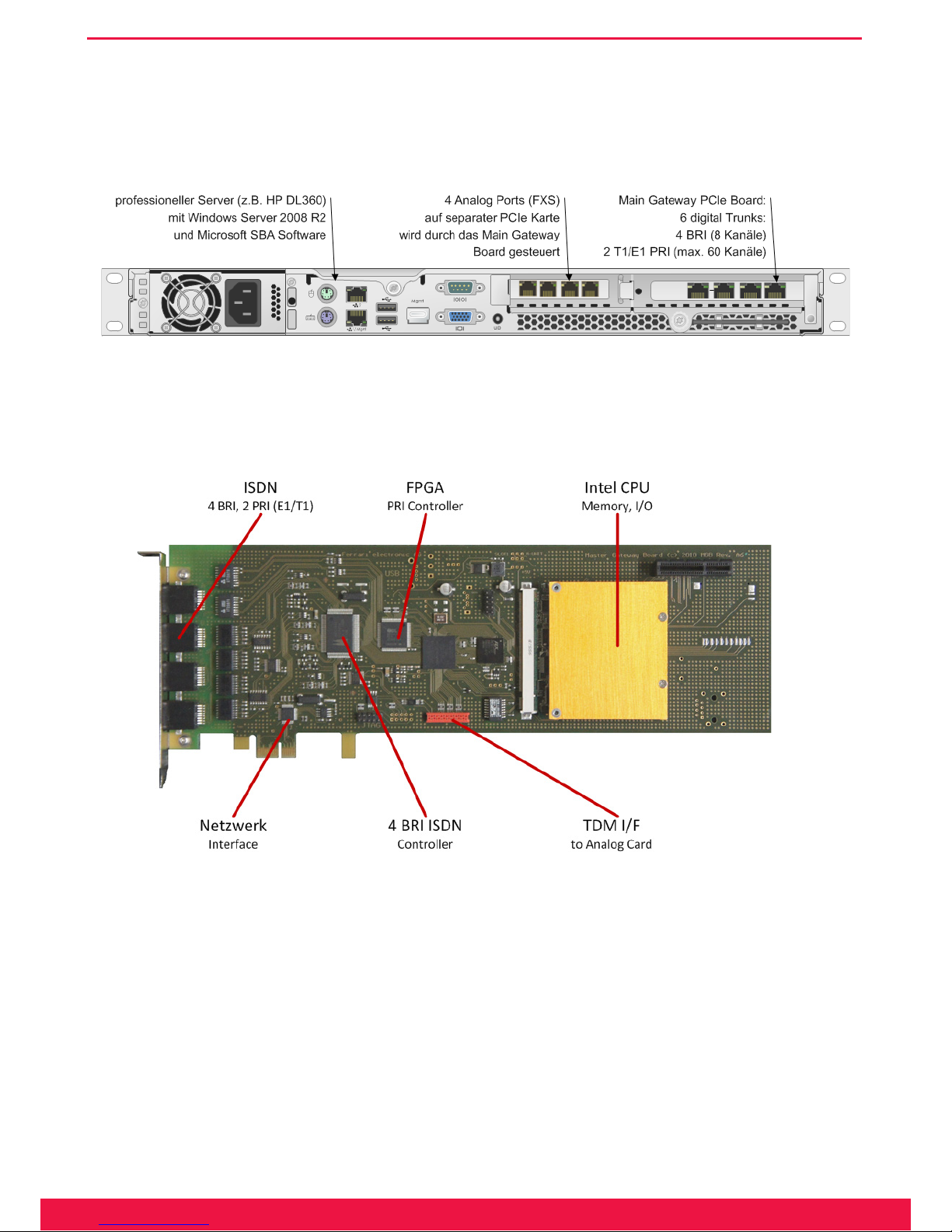
2.3 Installation of the Survivable Branch Appliance
2.3.1 Rear view of server machine
OfceMaster SBA is shipped as an Appliance with preinstalled components:
• Industrial grade server machine (e.g. HP ProLiant)
11
www.ferrari-electronic.com
Installation
• Main Gateway Board with 4BRI / 2PRI interfaces (can be licensed on demand)
• Separate 4FXS analog interface card (optional)
Separate Y-cables are available if all 4 BRI ports are to be used – the rst 2 BRI ports can be utilized using stan-
dard ISDN-cables.
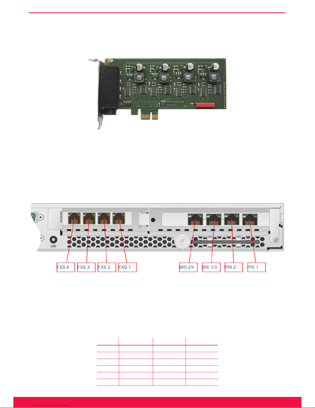
Image 2.1: Rear view SBA
2.3.2 Anatomy of the Media Gateway Board (MGB)
Image 2.2: Detailed view of Media Gateway Board
The Primary Rate Interface (E1/T1) is implemented in a FPGA (Field Programmable Gate Array), which con-
tains additional support algorithms. It can even be upgraded in the eld to implement more features as needed!
12
www.ferrari-electronic.com
Installation
2.3.3 Analog Card – 4 Port (FXS)
Four analog ports are contained on a separate low-prole PCI-Express Card connected to the main gateway
board using a at ribbon cable.
Image 2.3: Analog Card
The cable transports audio signals through a TDM bus as well as separate control information. High quality
faxing is possible since no VoIP technology is involved between PSTN and FXS ports.
2.3.4 ISDN and Analog Interfaces
Positions of analog and digital interface connectors are shown in this picture (rear view):
Image 2.4: Interfaces of the OfceMaster SBA
For BRI ports a separate Y-cable must be used if more than two BRI lines are needed.
Note!▼ Never use PRI 2 without PRI 1 – if only one PRI interface is connected always use PRI
1, otherwise clock synchronization will not work!
Table 2.2: Pin assignment
Pin PRI 1, PRI 2 BRI 1, BRI 2 BRI 3, BRI 4
1 Rx+ Tx+
2 Rx- Tx-
3 Tx+
4 Tx+ Rx+
5 Tx- Rx-
6 Tx-
13
www.ferrari-electronic.com
Installation
Pin PRI 1, PRI 2 BRI 1, BRI 2 BRI 3, BRI 4
7 Rx+
8 Rx-
Note!▼ If BRI interfaces are used in the US, a separate FCC approved NT1 Network Ter-
mination Unit must be installed to connect to OfficeMaster SBA S/T BRI ports.
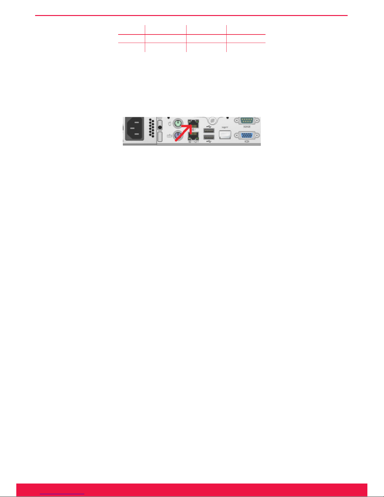
For LAN-connection, please plug in the network cable into the upper interface
(LAN1):
Image 2.5: LAN Port to be used
2.4 Recovery
2.4.1 Survivable Branch Appliance
Use of the Recovery USB Stick
The SBA system software can be reset to factory settings at any time by using the USB recovery stick.
Please follow these steps:
1. Connect the SBA device to Keyboard, Monitor and Mouse, either physically, using KVM or through tools
like HP ILO
2. Plug the USB stick into the front USB port
3. Power up SBA, it will automatically boot from the USB
4. At the end (message: press any key to shutdown computer) press a key
5. Remove USB stick
6. Power up SBA
7. Set the local Administrator password to OfceMaster!
8. Check network interface conguration (see below)
9. Open a cmd console and enter the following commands: %systemroot%\system32\inetsrv\appcmd.exe set
APPPOOL omsba_admin_pool -processModel.userName:ofmadmin %systemroot%\system32\inetsrv\appc-
md.exe set APPPOOL omsba_admin_pool -processModel.password:Sefte25AuTib
10. Now the deployment Web UI is ready for use
14
www.ferrari-electronic.com
Installation
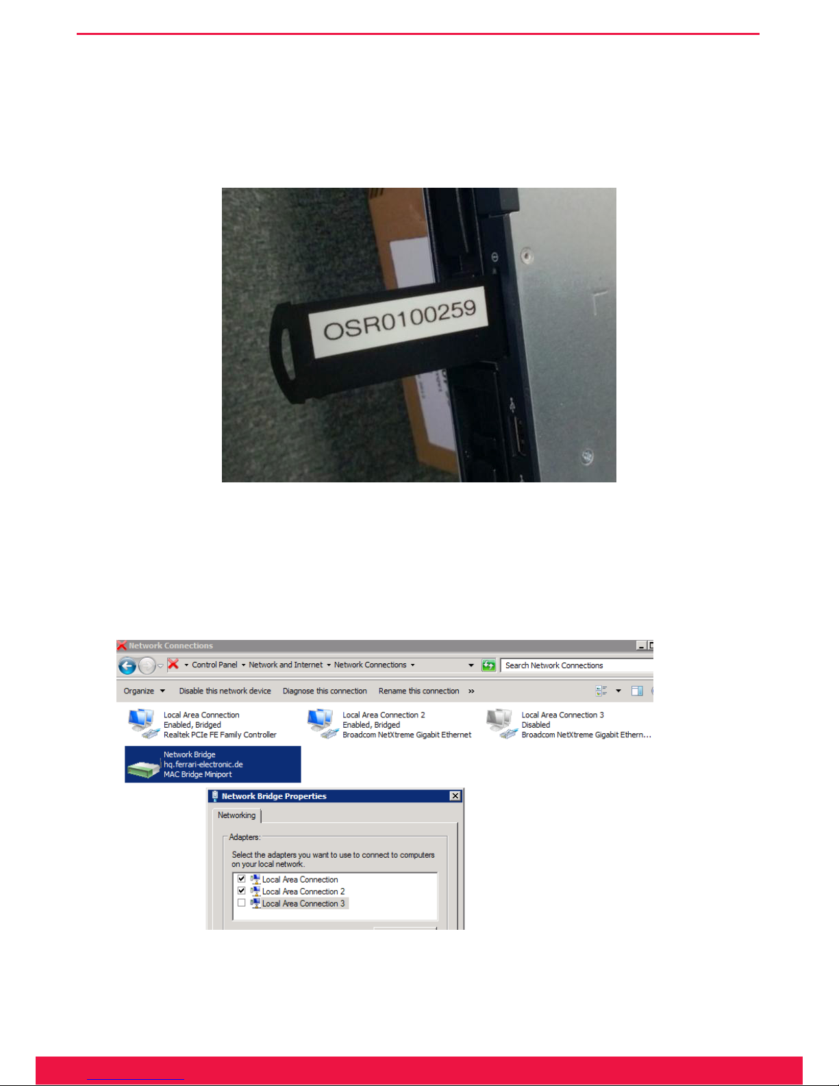
Note!▼ When a SBA is shipped, the serial number of the embedded gateway board is al-
ready preconfigured. After using the recovery image, the gateway serial number
will be queried later by the Web UI during deployment. The serial number of
the gateway board can be found on a card, which can be pulled out at the front
side:
Image 2.6: In this example the number to be entered is 259 (last 5 digits without leading zeros). (On some models, the number may be hand-
written and may contain the serial number only, without the prex, e.g. 234).
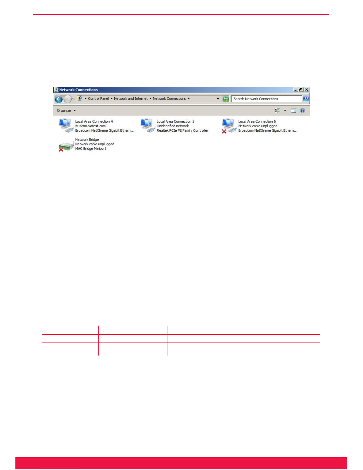
Check of the network interface configuration
During deployment of the Windows image via USB stick, the desired network conguration is automatically
established:
Image 2.7: Network bridge on the SBA
15
www.ferrari-electronic.com
Installation
This is the standard conguration, where the gateway board (can be identied as Realtek Controller) is bridged
with the LAN port (Local Area Connection 2), which is used for connecting to a switch. The unused second LAN
port (Local Area Connection 3) is disabled. In some situations (e.g. due to different BIOS revisions), the physical
LAN adapters have different internal id’s, meaning that the restored conguration must be corrected manually.
Image 2.8: Example of a network conguration that needs to be corrected
End of Example»
The necessary changes in this case are:
• Right click on Network Bridge – Properties
• Make Local Area Connection 4 (LAN Port) and Local Area Connection 5 (Gateway board) the only members
of the bridge
• Disable Local Area Connection 6
Now all network conguration settings should be made on the network bridge only. The SBA is ready for de-
ployment after a nal reboot.
2.5 Stainless steel box - Restore to factory settings
At the front as well as at the back of the case of the version for BRI‘s, there is one micro button each:
Table 2.3: Button on the stainless steel box
Micro button Resulting function Description
Micro button front Hardware Reset reboot system
Micro button rear Software Reset reset conguration parameters Function is deactivated one minute after
booting is completed (signaled by blinking diodes)
Reinstalling the software
Should OfceMaster Gate (in the stainless steel version with 4 BRI) stop working properly, a recovery can be
done with newer versions of the product (February 2011 onwards, distinguishable by the USB port on the side). To
do this, the Gateway needs to be disconnected from the power supply and the recovery stick from the bottom of the
case has to be plugged into the USB port. Afterwards, reconnect the Gateway to the power supply. Turn off the Gate-
way after roughly 30mins and remove the stick. When used afterwards, make sure a backup of the conguration is
loaded and, if needed, an update of the rmware is made.

Chapter 3
OfficeMaster Gate – Ferrari electronic AG
Configuration
17
www.ferrari-electronic.de
Configuration
3. Configuration
The products of the OfceMaster Gate family use a coherent rmware as a base, which operates the depending
on hardware available ports
Because of the coherent base and the therefore identical conguration-ports, every OfceMaster Gate of the 3rd
generation can be operated with the same user interface.
Even though the essential congurations of OfceMaster Gate are identical, when installing the SBA and the
Hybrid Gate, additional steps of conguration are necessary.
3.1 OfficeMaster Gate Basic Settings
If OfceMaster Gate is used solely in combination with the Unied Messaging Software OfceMaster, then the
conguration is made via the integrated administration program (see manual OfceMaster Administration). The
gateway function of OfceMaster Gate can be enabled if needed.
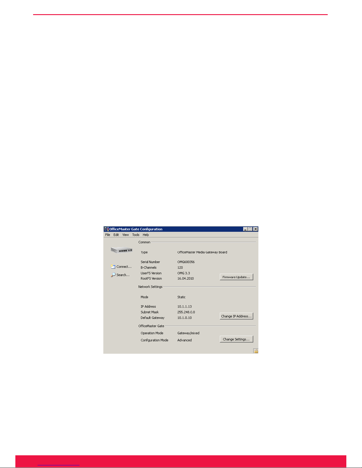
For the activation and conguration of the gateway function, an administration program (OmGateCong.exe,
installed via SetupOfceMasterGateCong.exe) is provided, which can be installed at any work space. A mixed use
as gateway and Unied Messaging Controller for OfceMaster can be set up with this program. The main dialog
will pop up after starting the conguration program:
Image 3.1: Connected OfceMaster Gate
Some of the elements will only become active, once a connection to the controller is provided (see next section).
Note!▼ The language can be changed between German and English in the help menu.
18
www.ferrari-electronic.de
Configuration
3.1.1 Connecting to OfficeMaster Gate
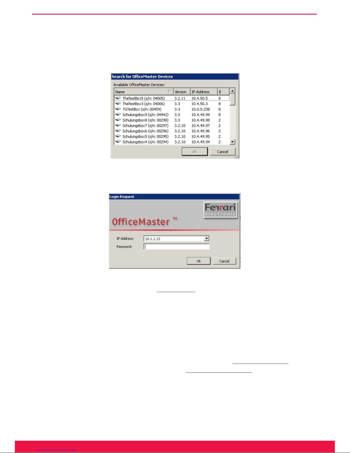
After the start of OfceMaster Gate conguration, the connection to OfceMaster Gate has to be established.
Via File > Search or by pressing the search symbol, name, IP address, version and number of channels of the found
controllers are listed:
Image 3.2: Available OfceMaster Gate in the Network
In this list, the preferred entry is selected and conrmed by pressing OK. A login dialog will then appear:
Image 3.3: Login dialog
This dialog can also be accessed directly via
File > Connect
, in order to enter the IP address of OfceMaster
Gate manually. For authentication purposes, a password is required.
Note!▼ The standard password on delivery is „omc“.
3.1.2 Network configuration
In order to change the network settings (for example IP address) the button
change IP address...
has to be
pressed. Alternatively the same can be achieved by going via
Edit > change IP address
. Depending on the struc-
ture of the used network, IPv4 and/or IPv6 addresses can be declared.

19
www.ferrari-electronic.de
Configuration
Image 3.4: Network settings
Note!▼ The configuration program communicates through UDP-Broadcasts via the port
3216. With OfficeMaster this also works through interposed switches, while
routers usually will not forward the Broadcast-Messages.
The mode activated on shipment of OfceMaster Gate is DHCP-Client. Possible modes of operation are DH-
CP-Server (IPv4 only), DHCP-Client and static.
DHCP-Server (IPv4)
The DHCP-Server mode is only useful for OfceMaster Gate, if OfceMaster Gate is connected to a host com-
puters network card via cross cable and when this network card is run in DHCP-Client mode.
DHCP-Client (IPv4)
This is the standard setting of OfceMaster Gate. In this mode of operation it is assumed, that there is a DH-
CP-Server existent in the network, which will assign the controller with an IP address and every other required val-
ue. OfceMaster Gate registers itself under the name that is shown in the rst slot of the IP conguration program.
If the DHCP-Server automatically initiates a DNS refresh then OfceMaster Gate can be contacted directly under
that name in the network.
Static (IPv4)
Is the network run without a DHCP-Server then OfceMaster Gate needs to get a static IP address, a subnetwork
mask, a gateway address (optional) as well as the address(es) of the DNS Server(s) assigned to it.
A Domain Server Name (DNS) has to be assigned, when the target systems are addressed via FQDN (Fully
Qualied Domain Name). Because these can, on occasion, malfunction, a alternative DNS should be congured as
DNS2.
20
www.ferrari-electronic.de
Configuration
Automatically
With this setting, an automatically assigned IPv6 address will be used.
Static IPv6 Address
Similar to IPv4, with IPv6 as well the declaring of a static IP address is possible. Are the target systems contacted
via FQDN (Fully Qualied Domain Name), at least on Domain Name Server (DNS) has to be declared. Since one
DNS server can always falter, and additional one should be congured as DNS2.
Proxy
A Proxy has to be set under the tab „Proxy“, should a connection in the network only possible via a Proxy.
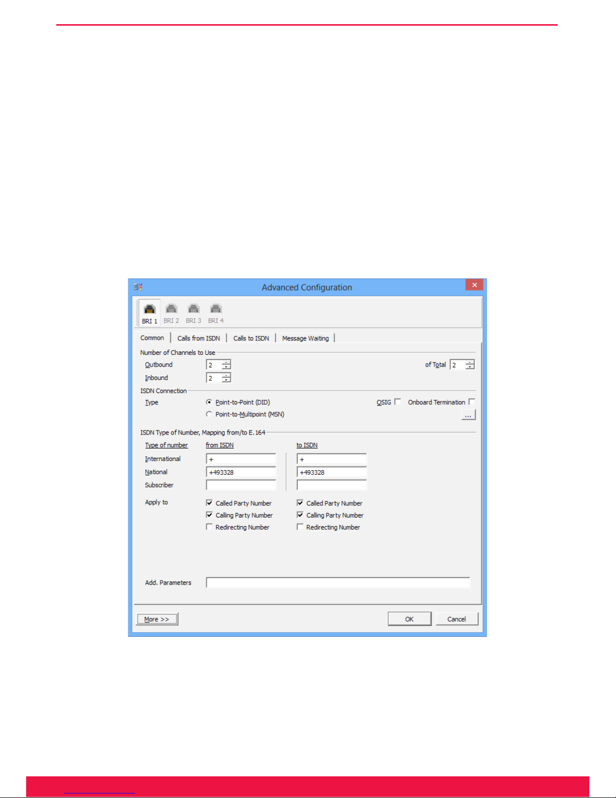
3.1.3 „Common“
Image 3.5: ISDN Settings
► Number of Channels to use
In the following it is decided, whether the existing B-Channels are to be used completely for in-and outgoing
connections or if, for example outgoing calls are only allowed to use a certain percentage, so that there are free
channels for incoming calls under any given circumstances.

21
www.ferrari-electronic.de
Configuration
► Outbound
Which number of channels will on maximum be used for outgoing calls.
► Inbound
Which number of channels will on maximum be used for inbound calls.
► of Total
Total of B-channels used.
►
[...]
-Button
By pressing the [...] button a dialog is opened, that enables the user to dene, which B-Channels can be
used at all, for example with „halved“ PRI ports. This „incomplete“ pin assignment is relatively common
outside of Germany.
► ISDN Connection
The different types of connection are Point-to-Multi point and Point-to-Point.
► Point-to-Point (DID)
Point-to-Point only supports one ISDN device, usually a telephone system or a media gateway. A Point-toPoint connection is assigned a complete dial through numbers area.
► Point-to-Multi point (MSN)
Point-to-Multi point connection only supports a limited number of receiver call numbers (usually 3 to 10),
so called MSN (Multiple Subscriber Number). Hereby multiple ISDN devices (Phone 1, Phone 2, Fax) can
be connected.
► QSIG
Additional to Euro-ISDN or DSS1, there is also QSIG. This is an ISDN protocol that is sometimes used
by a selective number of telephone systems. Via QSIG, additional information like the callers name can be
transmitted.
► Onboard Termination
OfceMaster Gate for BRI allows the addition of ISDN terminating resistors, which should usually be existent in the ISDN socket. By default, these internal terminating resistors are deactivated.
A LED can be found on the left side below the ISDN socket of OfceMaster Gate (stainless steel edition).
If this one is lid, then the rmware enabled the terminating resistors according the conguration settings.
Note!▼ Usage without terminating resistors can lead to ISDN errors. In older versions of
the hardware, this LED will be triggered if the terminating resistors are off! The
settings in the configuration program are in effect in any way
► NT Mode (Network Termination)
This option is usually used in order to place the gateway between the telephone network and the PBX.
Towards the telephone network the gateway acts like a PBX (as TE, meaning Terminal Equipment), while
towards the PBX it acts similar to the trunk.

22
www.ferrari-electronic.de
Configuration
Note!▼ This only works in Point-to-Point mode. Common terminals will not be usable on
this line as such devices usually run in Point-to-Multi point mode. Additionally,
a cross cable needs to be used for the connection with the PBX.
► [...]-Button – Advanced Connection Parameter
► Dial Timeout
When simulating an external line, numbers of any random length will be communicated by the telephone
system. In order to decide, which calls are supposed to be redirected outward, a timeout is set, after which
no more digits are to be expected. This timeout usually happens after 3-5 seconds.
► Caller Name Display Mode
Is QSIG activated in the ISDN protocol, caller names can be transmitted for incoming and outgoing calls.
Since this is based on different protocol versions depending on the system, testing is the only way to nd
the right setting.
► No L2 auto-activation (Point-to-Point Options)
With a Point-to-Point connection, the gateway will try to keep active the layers 1 and 2 in the D-Channel at
all times. This behavior can be deactivated here.
► ISDN Type of Number, Mapping from/to E.164
Type of Number is usually dened in ISDN in order to dene information about the type of call. Internally (for
example Lync or OfceMaster Suite) calls are usually in E.164 format, meaning that they need to be adjusted
properly.
► International
With calls from ISDN, the congured „call number“ (for example „+“) is fronted when the Type of Number
(TON) is set to „international“.
For outbound calls, meaning to ISDN, the TON is recognized via the congured call number and the call
number removed.
► National
National numbers are treated equivalently to international numbers.
► Subscriber
The local connection is entered under Subscriber.
► Apply to
Insert here, for which numbers the adaptations are to be made.
23
www.ferrari-electronic.de
Configuration
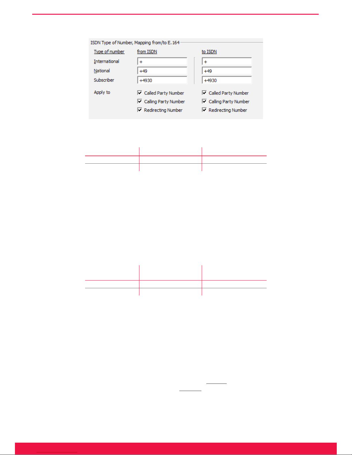
Example 3.1. Creating an E.164 number from TON for inbound calls
Image 3.6: Example for an automatic creation of an E.164 number
Table 3.1: Submitted information on inbound call
inbound signal Conversion into E.164
Called Party Number National 89123 +493055948
Calling Party Number Subscriber 55948 +4989123
With settings as seen in Image 4.6, the inbound signal from Table 4.1 is converted into an E.164 number. Af-
terwards, OfceMaster Gate’s set of rules are applied for further customization of the phone numbers and for the
delivery towards the appropriate destination as described in the following (4.1.4).
End of Example»
Example 3.2. Generating the ISDN information for outbound calls
For outbound calls the process is inverted. The settings of the sector ISDN apply.
Table 3.2: Conversion of E.164 to ISDN
Conversion into the
outbound signal
Phone number in
E.164
Called Party Number National 89123 +493055948
Calling Party Number Subscriber 55948 +4989123
End of Example»
Note!▼ More complex setting for TON are available via the creation of single rules for in-
bound, respectively outbound rules.
► More – Settings for multiple channels
OfceMaster Gate is available in versions with multiple ISDN channels. The conguration program supports
this by letting the user congure channels individually. Alternatively, all channels can be dened to copy the
settings of the rst channel. This can be activated via the button
More>>
in the conguration dialog. Here the
user denes which channels are to be used. Pressing
More<<
again hides the area. Has the individual conguration of the channels been selected, the upper area of the dialog will display the channels that are available
for conguration.
24
www.ferrari-electronic.de
Configuration
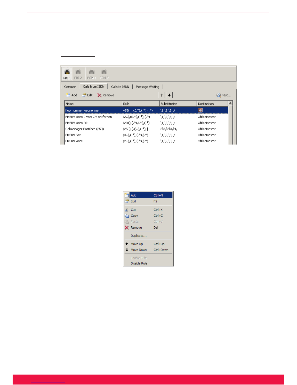
3.1.4 Calls from ISDN
For the selection of the target gateway, a separate tab is available in the advanced mode. In this tab, targets are
chosen depending on the calling number and reshaping can be done.
In the tab
Calls from ISDN
a list of the congured rules is shown:
Image 3.7: Rules for inbound calls
In this dialog you can add, delete, process and change the sequence of these rules. To edit, delete or move a rule,
click on it with the mouse button to select it and then select the action you require.
Additional options are offered by the context menu, which is opened by right clicking an entry:
Image 3.8: Context menu for Gateway rules
Many of these functions can be used with multiple rules at the same time. For this, the rules need to be selected
via multi-marking (Shift resp. Ctrl + left mouse button).
For when a new rule is created, the elds are set up to select any number and to remain unchanged after substi-
tution (substitution by itself.)
 Loading...