

Page 1
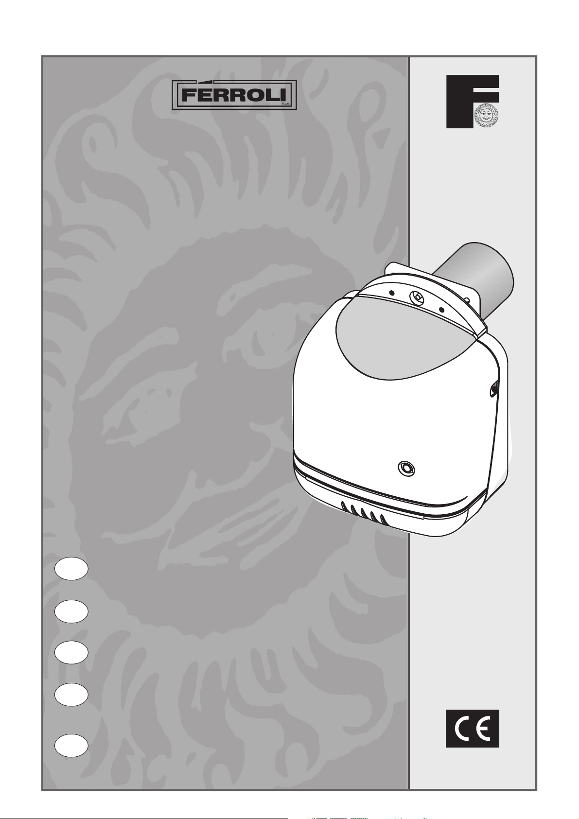
SUN G50 - G70
BRUCIATORE DI GASOLIO
OIL BURNER
BRULEUR DE FUEL
HEIZÖLBRENNER
QUEMADOR DE GASÓLEO
I
GB
FR
DE
ES
ISTRUZIONI PER L’USO L'INSTALLAZIONE
E LA MANUTENZIONE .............................................. 2
OPERATING, INSTALLATION
AND MAINTENANCE INSTRUCTIONS .................... 22
MODE D’EMPLOI,
INSTALLATION ET ENTRETIEN ............................... 42
BEDIENUNGS-, INSTALLATIONS-
UND WARTUNGSANLEITUNG................................. 62
INSTRUCCIONES DE USO, INSTALACIÓN
Y MANTENIMIENTO ................................................ 82
cod. 3544564/0 ediz. 07/2003
Page 2
SUN G50 - G70
Italiano
English
• Carefully read the warnings in this
instruction booklet, as they provide
important indications on the safety of
installation, operation and maintenance.
• The instruction booklet is an integral
and essential part of the product and
must be carefully kept by the user for
future reference.
• The installation and maintenance
operations must be performed
according to the standards in force, the
instructions of the manufacturer and
must be carried out by professionally
qualified personnel.
• Incorrect installation or poor
maintenance may cause damage to
people, animals or things. The
manufacturer declines all liability for
damage deriving from errors in the
installation and operation of the
appliance, and in any case from the
failure to observe the instructions
provided by the manufacturer.
• Before performing any cleaning or
maintenance operations, disconnect the
appliance from the mains power supply
using the system switch and/or the
corresponding on-off devices.
• In the event of faults and/or poor
operation of the appliance, it should be
deactivated. Do not attempt to repair
the appliance. Contact professionally
qualified personnel only.
• After having removed the packaging,
check that the contents are intact.
• The parts of the packaging must not be
left within the reach of children, as they
are potential sources of danger.
Français
Deutsch
Certification
The CE Mark attests that Ferroli appliances conform to the requirements specified in the corresponding
European directives.
In particular, this appliance conforms to the following EEC directives:
• Directive 92/42, Efficiency, accepted into Italian law by Presidential Decree no. 660, 15.11.96
• Directive 73/23, Low Voltage, (amended by no. 93/68)
• Directive 89/336, Electromagnetic Compatibility (amended by no. 93/68) accepted into Italian law
by Presidential Decree no. 615, 15/11/96
This symbol indicates “Warning” and is placed near all warnings regarding safety. Such
provisions must be strictly adhered to so as to avoid danger and damage to people, animals
and things.
This symbol highlights a note or an important warning
1. Operating instructions ........................................................................ 23
2. Installation........................................................................................... 24
Español
22
3. Service and maintenance..................................................................... 31
4. Characteristics and technical specifications ........................................ 39
Page 3
SUN G50 - G70
1. OPERATING INSTRUCTIONS
1.1 Introduction
Dear Customer,
Thank you for choosing SUN G50 - G70, a twin-stage Ferroli burner featuring advanced design, cutting-
edge technology, high reliability and quality construction.
The SUN G50 - G70 is an oil burner, whose compact dimensions and original design make it ideal for use
with most of the boilers currently present on the market. The attention paid to its design and industrial
production has resulted in a product that is well-balanced with very low CO and NOx emissions and a very
silent flame.
1.2 Operating instructions
The operation of the burner, once correctly installed and adjusted, is
completely automatic and does not require any intervention by the user.
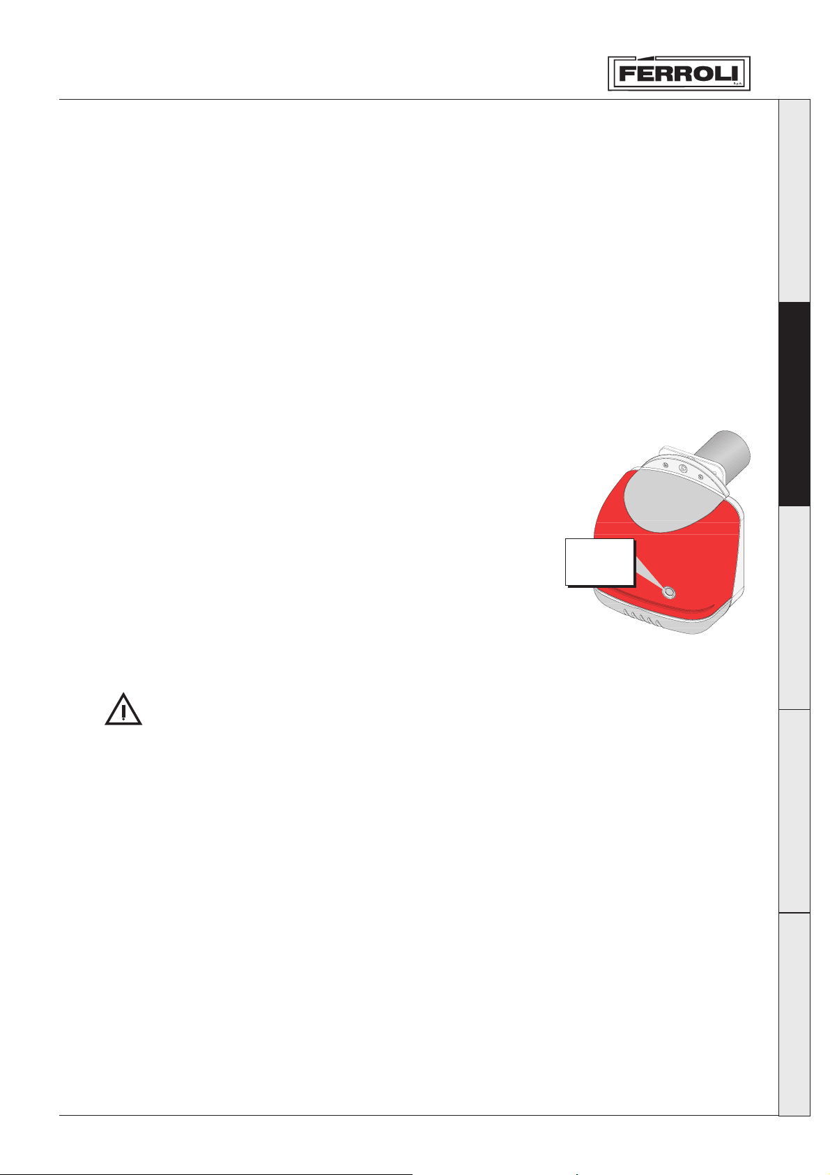
In the event of no fuel or operating anomalies, the burner stops and
shuts-down (the red light on the reset button turns on). It is recommended
to replete the supply of fuel before it runs out completely, to avoid the
inlet of air (irregular operation of the burner) or the loss of prime of the
pump (in which case the assistance of the service centre is required).
If the fuel tank is outside, in areas where the temperature falls below -10
°C, the tank and fuel supply pipes must be adequately protected. Use
winter oil or add a specific anti-freeze.
Make sure that the room where the burner is installed is free of
inflammable objects or materials, corrosive gas or volatile substances,
and is not dusty. Dust, in fact, is sucked in by the fan and sticks to the
blades of the rotor and reduces air flow, or alternatively blocks the flame
stability disk, compromising efficiency.
Burner
reset
button
fig. 1
Italiano
English
Français
Do not allow the burner to be tampered with by inexpert persons or children.
1.3 Maintenance
Make sure that maintenance is performed on the burner periodically, at least once a year. The
maintenance operations must be performed by qualified and specialist personnel according to the
indications contained in chapter 3.
1.4 Anomalies
If the burner does not ignite and the red light on the reset button is not on, check that there is electrical
power, that the heating system switch is on, that the fuses are intact and that there is an effective request
for heat from the boiler.
If the burner is still off (red light on the reset button on), press the reset button to reset operation. The
burner will attempt to ignite. If it shuts down again, check that there is fuel in the tank and that the manual
valves located on the oil supply pipe are open. If these checks do not resolve the problem, contact the
service centre.
If noise is produced during the operation of the burner, contact the service centre.
Deutsch
Español
23
Page 4
2. INSTALLATION
SUN G50 - G70
Italiano
2.1 general instructions
English
2.2 installation in the boiler
Français
This appliance must only be used for the purposes it has been specifically designed for. This appliance may
be applied, according to its characteristics, performance and heating capacity, to water boilers, steam
boilers, diathermic oil boilers and other utilities, as expressly envisaged by the manufacturer of such. All
other uses are considered improper and thus dangerous.
The appliance may not be opened nor its components tampered with, except for the parts included in the
maintenance operations. The appliance may not be modified to alter its performance or use.
If the burner is fitted with optional devices, kits or accessories, only original products should be used.
THE BURNER MUST ONLY BE INSTALLED AND ADJUSTED BY QUALIFIED AND SPECIALIST
PERSONNEL, IN COMPLETE COMPLIANCE WITH ALL THE INSTRUCTIONS REPORTED IN
THIS TECHNICAL MANUAL, THE LEGAL STANDARDS IN FORCE, THE PRESCRIPTIONS OF
THE UNI AND CEI STANDARDS AND ANY LOCAL STANDARDS, AND ACCORDING TO THE
RULES OF GOOD PRACTICE.
Place of installation
The room in which the boiler and burner are installed must have openings to the outside according to the
standards in force. If the same room features a series of burners or air inlet devices that can operate at
the same time, the ventilation openings must be large enough for the simultaneous operation of all the
appliances.
The place of installation must be free of inflammable objects or materials, corrosive gas, dust or volatile
substances that, sucked in by the fan, may block the internal tubing of the burner or the combustion head.
The environment must be dry and not exposed to rain, snow or frost.
Deutsch
Español
24
Page 5
SUN G50 - G70
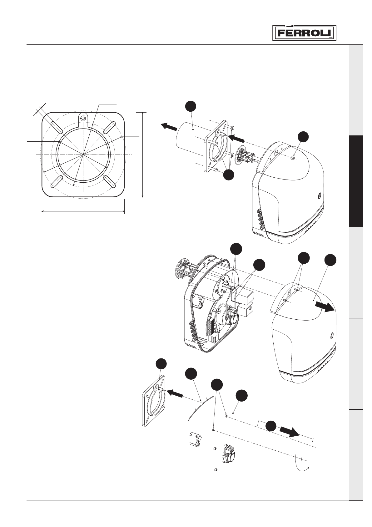
Burner flange
Ø225
11
Italiano
A
Ø182
260
fig. 2a
Assembly sequence
1) Drill the plate closing off the
combustion chamber, observing
the dimensions given in Fig. 2a.
2) Separate the flange/nosepiece
“A” from the burner body by
unscrewing the nut “B”.
3) Secure the flange/nosepiece “A”
to the boiler body with the
screws “C”.
4) Take off the burner casing “D”
by unscrewing the two screws
“E”.
5) Unscrew the couplings “L” and
take out the copper pipes “M”.
6) Slightly unscrew the two screws
“F”, turn and extract the
combustion head “G”.
7) Insert the burner body onto the
pin “H” and secure it onto the
flange with the screw “B”.
8) Fit the combustion head back on
after checking that the nozzles
are suited to the power of the
boiler.
9) Connect the oil hoses to the
pump.
10) Check the settings.
11) Fit the casing “D” back on and
secure it with the screws “E”.
Ø290
260
B
English
C
L
E
M
D
Français
Deutsch
H
B
F
I
G
Español
fig. 2b
25
Page 6
Italiano
SUN G50 - G70
2.3 Fuel supply
General instructions
The burner must be supplied by the type of fuel it is set for, as shown on the rating plate on the appliance
and in the table of technical specifications in Chap. 4.3 of this manual.
The pipe supplying fuel to the burner must be perfectly sealed, to avoid air entering into the pump, must
be fitted with a filter upstream of the burner, and all the safety and control devices required by the
standards in force. There must be no impurities or processing residues inside the pipe: clean the pipes
before using.
In addition, before operating the burner, make sure that the fuel return pipe is not blocked. Excessive
backpressure will break the pump seal device.
The tank must be positioned as required by the standards in force, and must be built and installed in a
way that no water or impurities may enter. The tank must be carefully cleaned before filling with fuel.
The tank and supply pipe must be protected from frost.
English
Français
Deutsch
Hydraulic circuit
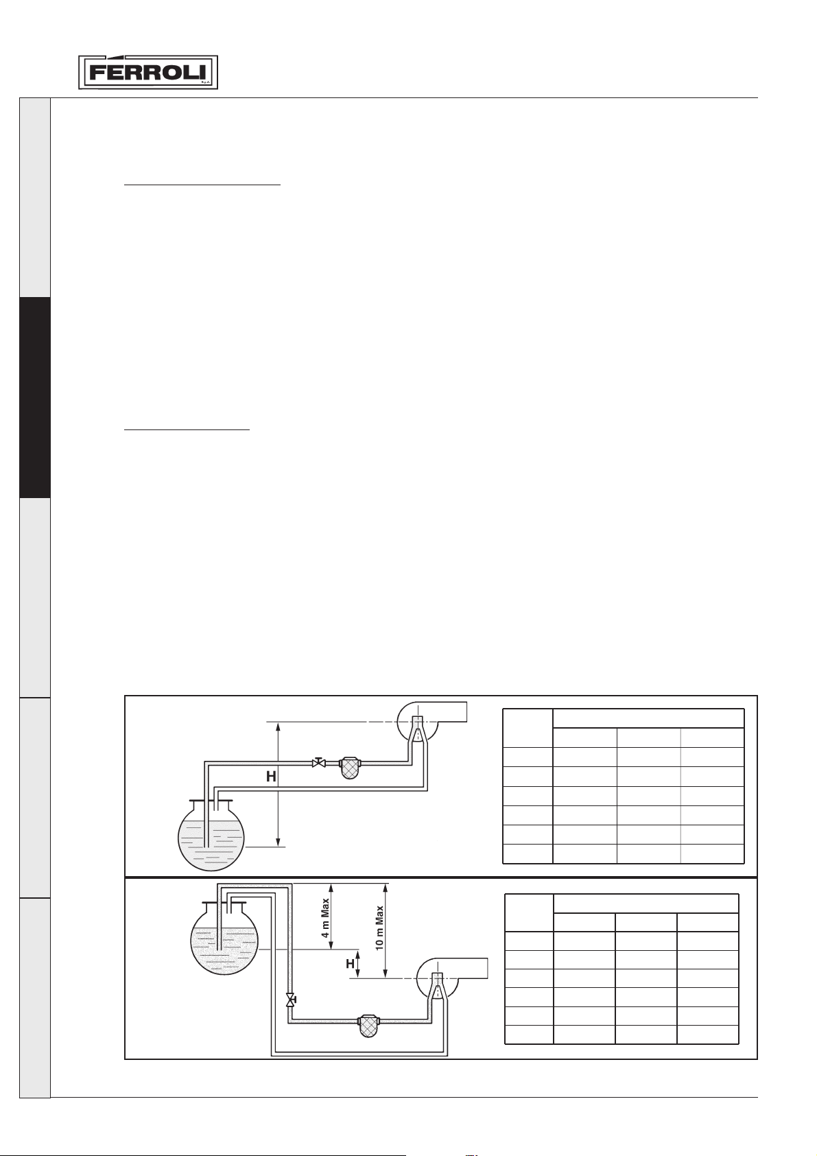
The burner is fitted with a self-suction pump that can supply itself autonomously, within the limits shown
below. The fuel supply circuits can be divided into 3 types, as shown in the following figure:
A Suction feed
B Siphon feed
C Ring feed
For each type of system there is a table for sizing the supply pipe in relation to the length (L) of the inlet
pipe, and the difference in height (H) from the tank. Do not exceed the MAX distances shown in the figures
so as not to excessively stress the pump seal devices.
A
fig. 3a
H
(m)
Øi 12 mm. Øi 14 mm.
0
0,5
1,0
2,0
3,0
4,0
36
32
28
19
10
3
L (m)
74
66
56
42
26
10
Øi 16 mm.
137
123
109
81
53
25
Español
26
B
fig. 3b
H
(m)
Øi 12 mm Øi 14 mm
0
0,5
1,0
2,0
3,0
4,0
36
40
44
58
62
71
L (m)
74
82
90
106
122
138
Øi 16 mm
137
150
150
150
150
150
Page 7
SUN G50 - G70
C
Nota: for each curve or gate valve, add 0.25
metres to the length of the pipe (pressure
drop).
L Total length of the inlet pipe, including the
vertical sections
H Difference in height
fig. 3c
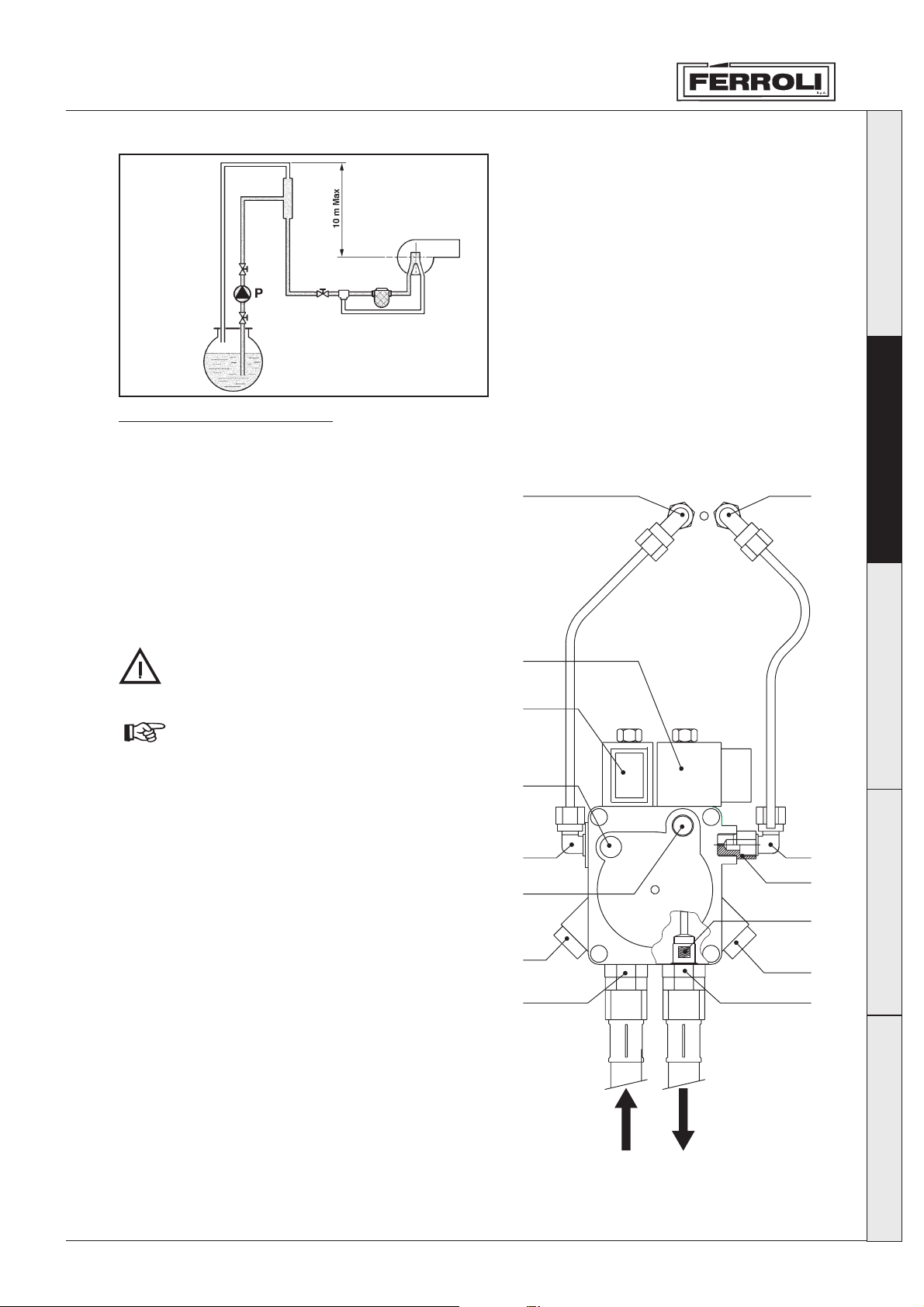
Connection to the pump
The burner leaves the factory with the internal pump bypass closed, that is, the burner is fitted for twopipe connection. Remove the caps and connect the two flexible pipes to the pump inlet (1) and return (2),
as shown in Figure 4, making sure the flexible pipes
are not twisted and that they are positioned so that
they will not be stepped on or come into contact with
the hot parts of the boiler.
If the internal pump bypass needs to be used for
single-pipe connections, remove the bypass screw
(10) and cap the return fitting (2) on the pump,
connecting only the flexible pipe to the inlet fitting (1).
Øi Internal diameter of pipes
P Auxiliary pump
12
13
Italiano
English
Français
If the pump is operated with the return closed
and the bypass screw inserted, it will be
damaged immediately.
In particular, with single-tube systems, if the
fuel inlet pipe is initially empty, the air
contained in the pipe must be vented for the
fuel pump to be primed. It is recommended,
before igniting the burner, to loosen the
pressure gauge connection (5) screw on the
pump and then perform the ignition cycle.
When the oil comes out of the screw, the
pump is primed. Switch off the burner and
tighten the screw.
Key
1 Suction
2 Return with internal by-pass screw
3 Delivery to the 1st stage nozzle
4 Delivery to the 2nd stage nozzle
5 Pressure gauge connections
6 Vacuum gauge connection
7 Pump pressure adjustment
8 1st stage coil
9 2nd stage coil
10 By-pass screw
11 1/8” reduction with hole Ø1
12 1st stage nozzle
13 2nd stage nozzle
9
8
6
3
5
4
11
Deutsch
10
7
5
1
2
Español
fig 4
27
Page 8
Italiano
SUN G50 - G70
2.4 Nozzle and Electrodes
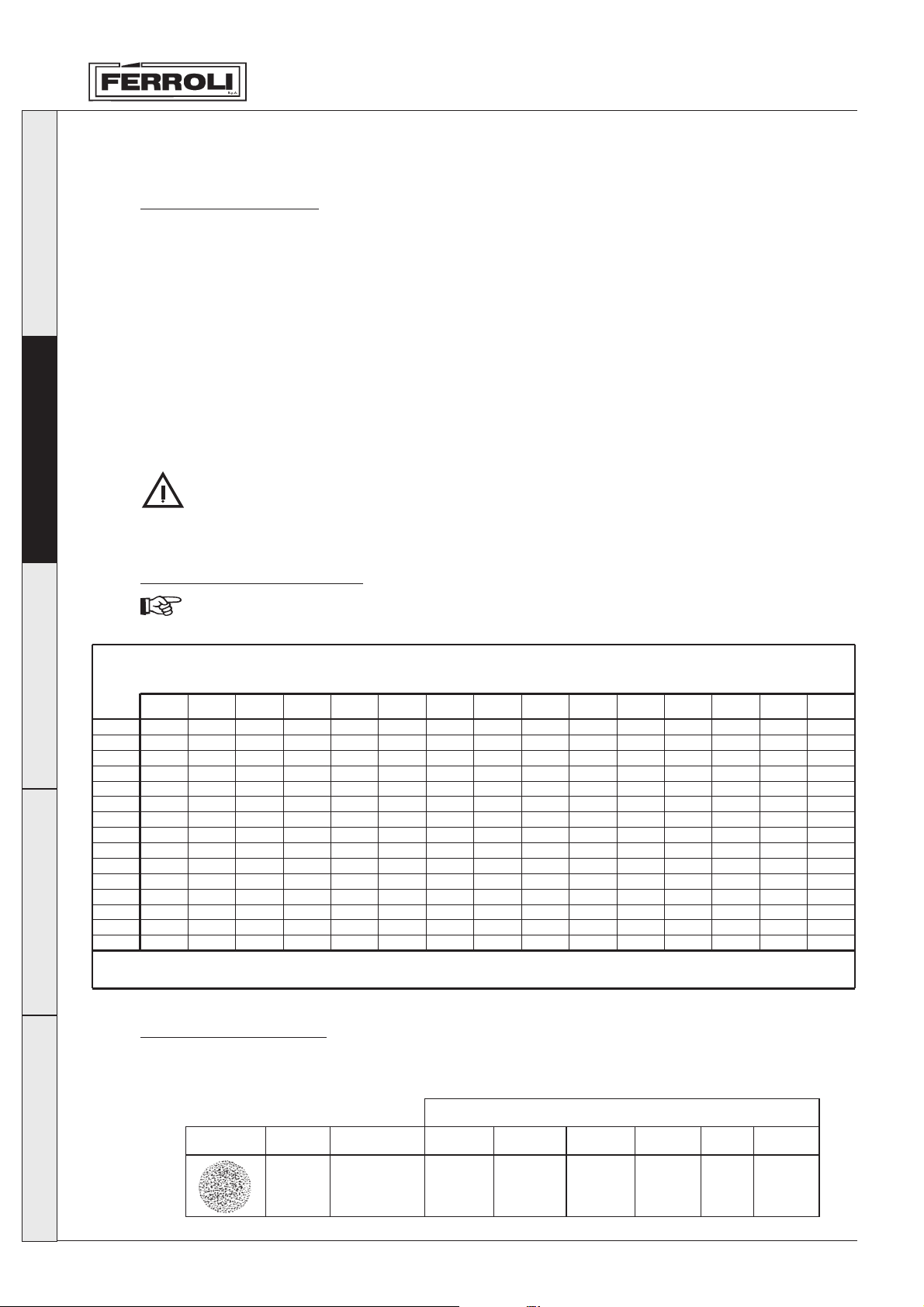
Choosing the nozzle
Determine the required fuel flow-rate, based on the heat input of the boiler and the minimum heat output
(Hi) of the fuel used (ref. technical data table in chap. 4). Based on the flow-rate calculated, use the table
below, according to the pump pressure, to determine the most suitable nozzle size (in GPH). The bold
values in the table are the most suitable for burner operation.
Both nozzles should be chosen from the ones indicated in the following table.
The first nozzle determines the burner flow rate in the 1st stage.
The second nozzle words together with the first one and both determine the burner flow rate in the 2nd
stage.
The flow rates of the 1st and 2nd stage must come within the values given in the technical data table in
paragraph 4.3.
It is recommended for the 1st-stage nozzle to have a delivery of between 55-60% of the total flow rate.
English
Nozzle
Français
Deutsch
GPH
3,50
4,00
4,50
5,00
5,50
6,00
6,50
7,00
7,50
8,30
9,50
10,50
12,00
13,80
15,30
The two nozzles supplied can be used when they correspond to the required flow rate. If they
do not, they should be changed with another two whose delivery is suited to the system.
Oil nozzle flow-rate table
The values given in the table are approximate since it is necessary to bear in mind that the nozzle
deliveries may vary by ± 5%.
Pump pressure (bar)
8 9 10 11 12 13 14 15 16 17 18 19 20 21 22
11,90
13,60
15,30
17,00
18,70
20,40
22,10
23,79
25,49
28,21
32,29
35,69
40,80
46,90
52,00
12,62
14,42
16,22
18,03
19,83
21,63
23,44
25,24
27,04
29,93
34,25
37,86
43,30
49,80
55,20
13,30
15,20
17,10
19,00
20,90
22,80
23,70
26,60
28,50
31,54
36,10
40,06
45,60
52,40
58,10
13,95
15,94
17,94
19,93
21,92
23,92
25,91
27,90
29,90
33,08
37,87
41,73
47,80
55,00
61,00
14,57
16,65
18,73
20.82
22.90
24,98
27,06
29,14
31,22
34,55
39,55
43,74
50,00
57,50
63,70
15,17
17,33
19,50
21,67
23,83
26,00
28,17
30,33
32,50
35,97
41,17
45,41
52,00
59,80
66,30
15,74
17,99
20,24
22,48
24,73
26,98
29,23
31,48
33,73
37,32
42,72
47,20
54,00
62,10
68,80
16.29
18,62
20,95
23,27
25,60
27,93
30,26
32,56
34,91
38,63
44,22
48,90
55,90
64,20
71,10
16,83
19,23
21,63
24,04
26,44
28,84
31,25
33,65
36,05
39,90
45,67
50,50
57,70
66,30
73,60
17,34
19,82
22,30
24,78
27,25
29,73
32,21
34,69
37,16
41,13
47,07
52,00
59,50
68,40
75,80
17,85
20,40
22,95
25,49
28,04
30,59
33,14
35,69
38,24
42,32
48,44
53,50
61,20
70,40
78,00
18,34
20,95
23,57
26,19
28,81
31,43
34,05
36,67
39,29
43,48
49,77
55,00
62,90
72,30
80,20
18,81
21,50
24,19
26,87
29,56
32,25
34,94
37,62
40,31
44,61
51,06
56,40
64,50
74,30
82,20
19,28
22,03
24,78
27,54
30,29
33,04
35,80
38,55
41,31
45,71
52,32
57,80
66,10
76,00
84,30
19,73
22,55
25,37
28,19
31,00
33,82
36,64
39,46
42,28
46,79
53,55
59,20
67,60
77,80
86,20
Español
28
Flow-rate at the outlet in kg/h
Table of spray values
The nozzles are available with different sprays, identified by one or more letters, depending on the
manufacturer. The table shows the most suitable types of spray for the burner.
Type of nozzle
ES
Fluidics
SF - S
SPRAY Angle
60°
Type of cone
Full
Delavan
B
Monarch
AR
Danfoss
S
Steinen
S - SS
Hago
Page 9
SUN G50 - G70
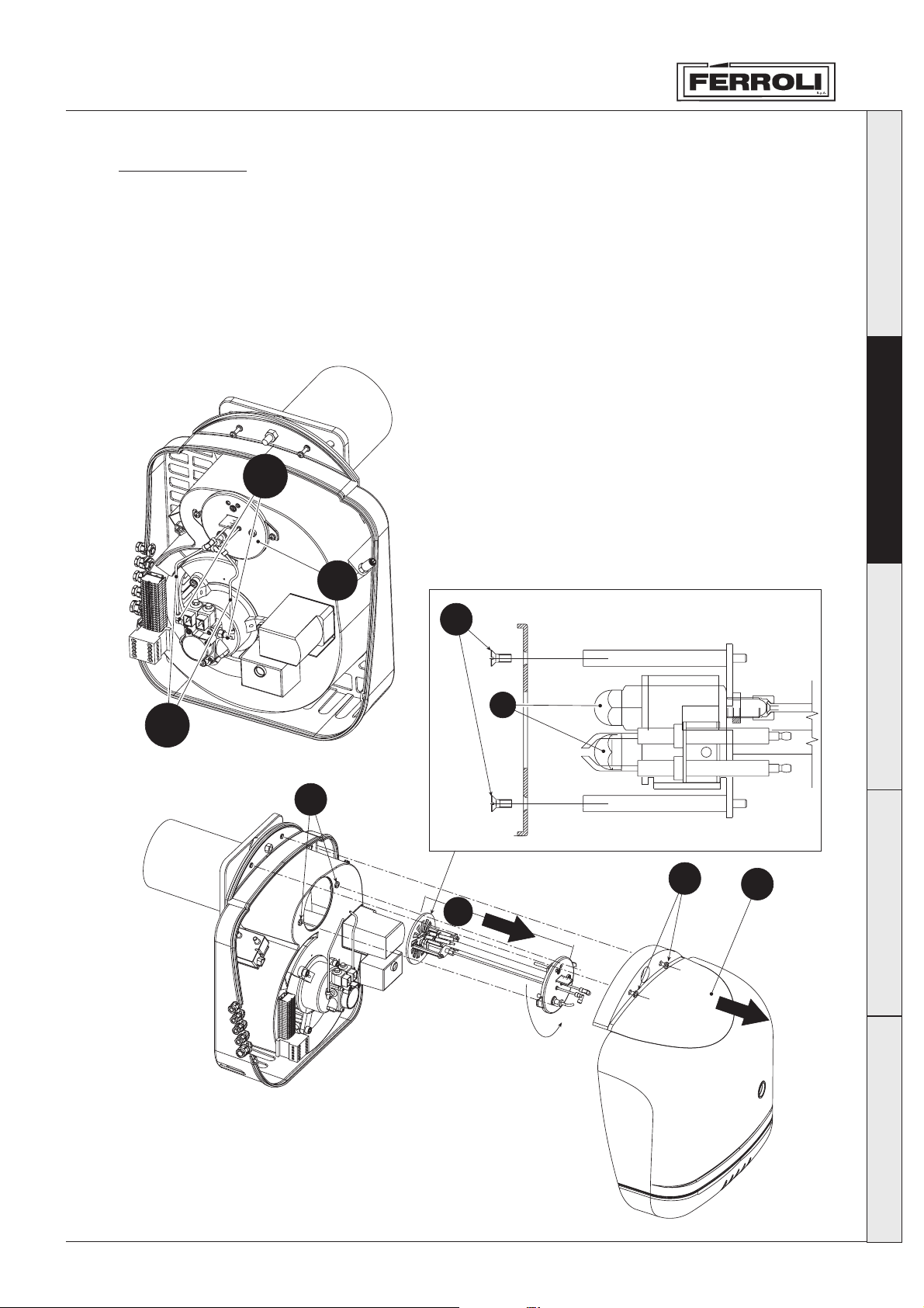
Fitting nozzles
After determining the right nozzles to use, go ahead and fit them as follows:
1 Unscrew the screws “A”
2 Take off the casing “B”
3 Using a wrench, unscrew the couplings “C” by half a turn
4 Take the copper tubes “D” out of the couplings
5 Slightly unscrew the screws “E”
6 Turn and take out the head/nozzle-holder assembly “F”
7 Unscrew the two screws “G”
8 Using a wrench, unscrew the nozzles “I”
C
Italiano
English
D
F
G
Nozzle
2nd stage
I
Nozzle
1st stage
E
A
B
F
Français
Deutsch
fig. 5
Español
29
Page 10
Italiano
English
SUN G50 - G70
Electrode positioning
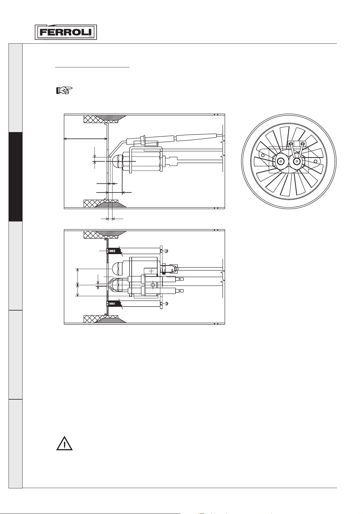
After fitting the nozzles, check the electrodes and baffle are in the right positions, according to the
distances shown below.
The distances should be checked after any work done on the head.
Combustion head
L
5,5
2,5
19
Français
2.5 Electrical connections
Deutsch
5,5
2215
The burner is fitted with a multi-pole socket for the electrical connections; refer to the wiring diagram in
Chapter “4 Characteristics and technical specifications” for the connections. The following connections
are to be performed by the installer:
• power line
• thermostat line
• any shut-down and/or hour counter lights
4
fig. 6
Español
30
The length of the connection cables must allow the burner, and the boiler door, if required, to be opened.
In the event of faults involving the burner power cable, it should only be replaced by specialist persons.
The burner should be connected to a single-phase, 230 Volt-50 Hz electrical line.
Have professionally qualified personnel check the efficiency and the suitability of the earth
system; the manufacturer is not responsible for any damage caused by the failure to earth the
system. Also check that the electrical system is adequately rated for the maximum power
absorbed by the appliance, indicated on the boiler rating plate.
The correct polarity must be respected (PHASE: brown wire / NEUTRAL: blue wire / EARTH:
yellow - green wire) in the electrical connections.
Page 11
SUN G50 - G70
3. SERVICE AND MAINTENANCE
All the adjustment, commissioning and maintenance operations must be performed by Qualified
Personnel, in compliance with the standards in force. The local sales organisation and Customer Service
Centre is available for any further information.
FERROLI S.p.A. declines all liability for damage to persons and/or things deriving from tampering with
the appliance by non-authorised persons
3.1 Adjustments
Air lock and head adjustments
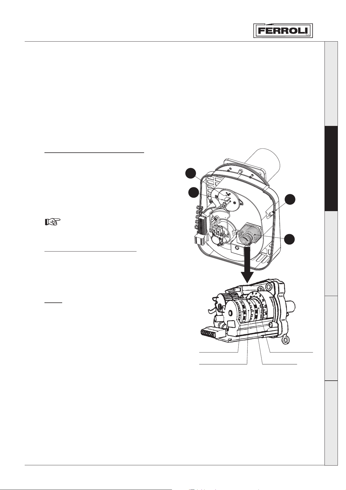
The head adjustment depends on the burner’s
delivery and is performed by turning the adjustment
screw “B” clockwise or anticlockwise.
This changes the position of the baffle in relation to
the nosepiece and accordingly the air passage.
To adjust the air delivery, turn the screw “C” for the
2nd stage and “D” (orange cam) for the 1st stage.
To limit dispersion to the flue with the boiler
turned off, the burner is equipped with a
gravity-operated air lock that shuts
automatically when the burner stops.
Combustion air adjustments
The air lock is operated by the servomotor.
The fully open/shut positions are adjusted on the
cams, turning anticlockwise to increase the opening
of the lock and clockwise to decrease it.
B
A
Italiano
English
C
Français
D
Cams
Blue cam - Fully closed position 0°.
do not alter
Orange cam - 1st stage air adjustment.
Red cam - Fully open position 85°.
do not alter
Black cam - Signal to open the
2nd-stage solenoid valve.
Key
A Head adjustment pointer
B Head adjustment screw
C 2-nd stage air adjustment screw
D Servomotor for the 1st-stage adjustment and signal to open the solenoid valve
Black cam
Orange cam
fig. 7
Deutsch
Red cam
Blue cam
Español
31
Page 12
SUN G50 - G70
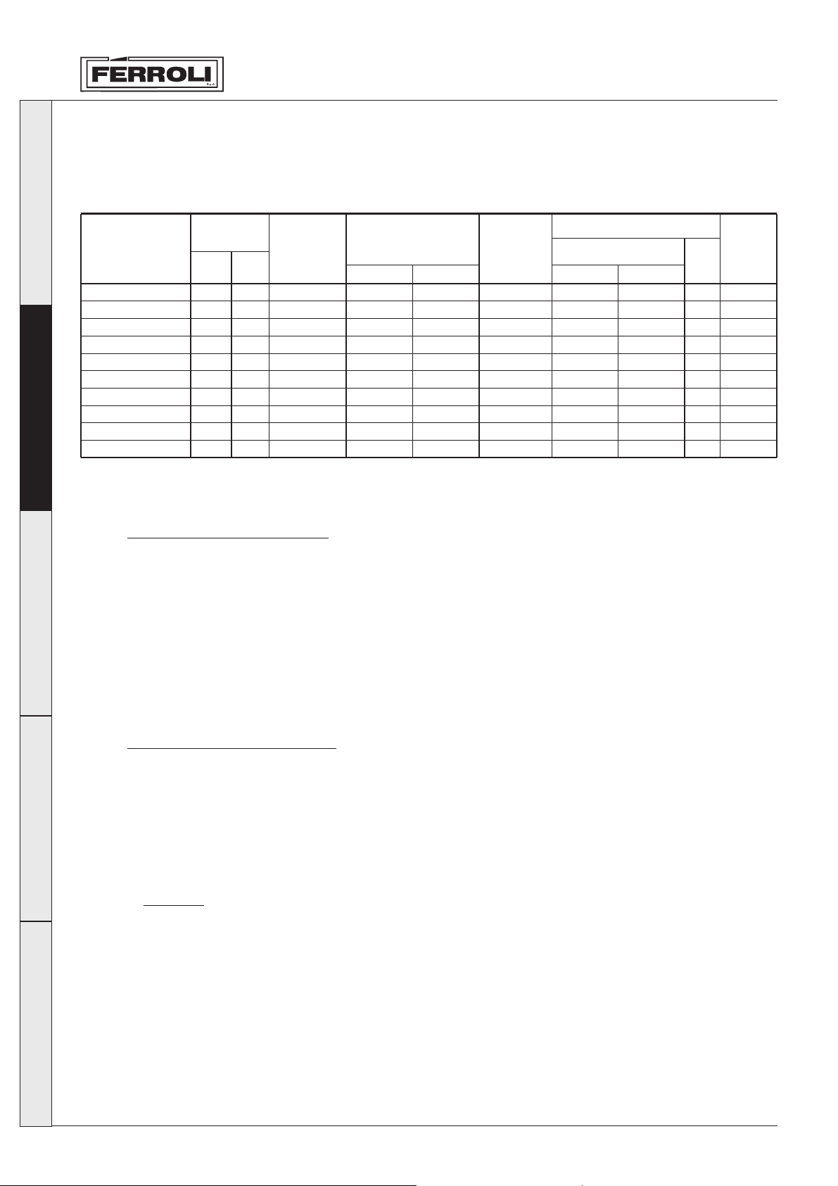
To perform a preliminary adjustment of head and air damper during installation (before commissioning
and consequently calibrating the appliance using instruments), use the graph below:
Italiano
GN4.10
GN4.11
GN4.12
GN4.13
GN4.14
Prextherm N 400
Prextherm N 500
Prextherm 550
English
Prextherm 620
Prextherm 800
Model
Heat
output
MaxkWmin
kW
388
229
452
266
516
309
600
352
695
416
435
279
541
345
598
359
674
404
870
522
Burner
G50
G50
G50
G70
G70
G50
G50
G70
G70
G70
Nozzles
1st stage
4,5
5
6
7
8,5
5,5
7,5
7
8,5
10,5
2nd stage
3
3,5
4
5
5,5
3,5
4,5
5
5,5
7
Pump
pressure
bar
12
14
13
12
12
12
11
12
12
12
Servomotor
1st stage
12°
13°
14°
8°
10°
14°
16°
8°
10°
15°
air
2nd stage
10
17
20
10
15
20
25
10
15
25
EV
15°
15°
20°
15°
15°
15°
15°
15°
15°
20°
L (mm)
27
24
22
22
22
23
22
22
22
22
Adjusting pump pressure
The pressure of the pump is factory-set to 12 bars, for optimum operation, and normally should not be
modified. Nonetheless, if under specific circumstances a different pressure needs to be set, once having
attached the pressure gauge and ignited the burner, use the adjustment screws “6” indicated in fig. 4.
In any case, it is recommended to keep within the range 10 - 14 bars.
Français
3.2 Commissioning
Deutsch
Checks to be performed on first ignition, and after all maintenance operations that involve the
disconnection of the appliance from systems or intervention on the safety devices or parts of the burner:
Before igniting the burner
• Check that the burner is correctly fastened to the boiler, and the preliminary adjustments described
previously have been performed.
• Make sure that boiler and the system have been filled with water or diathermic oil, that the valves in
the water circuit are open and that the flue gas exhaust pipe is free and correctly sized.
• Check that the boiler door is closed, so that the flame only propagates inside the combustion chamber.
• Fit the pressure gauge and the vacuometer to the pump (removed before operation).
• Open the gate valves in the oil pipes, making sure that there is fuel in the tank and that the return pipe
is not blocked.
Attention: Blockages may cause the pump seal device to break.
Español
32
Page 13
SUN G50 - G70
Igniting the burner
• Connect electrical power by closing the main switch upstream of the burner
• Close the thermostat line (boiler/room)
• Reset the appliance (pressing the red button)
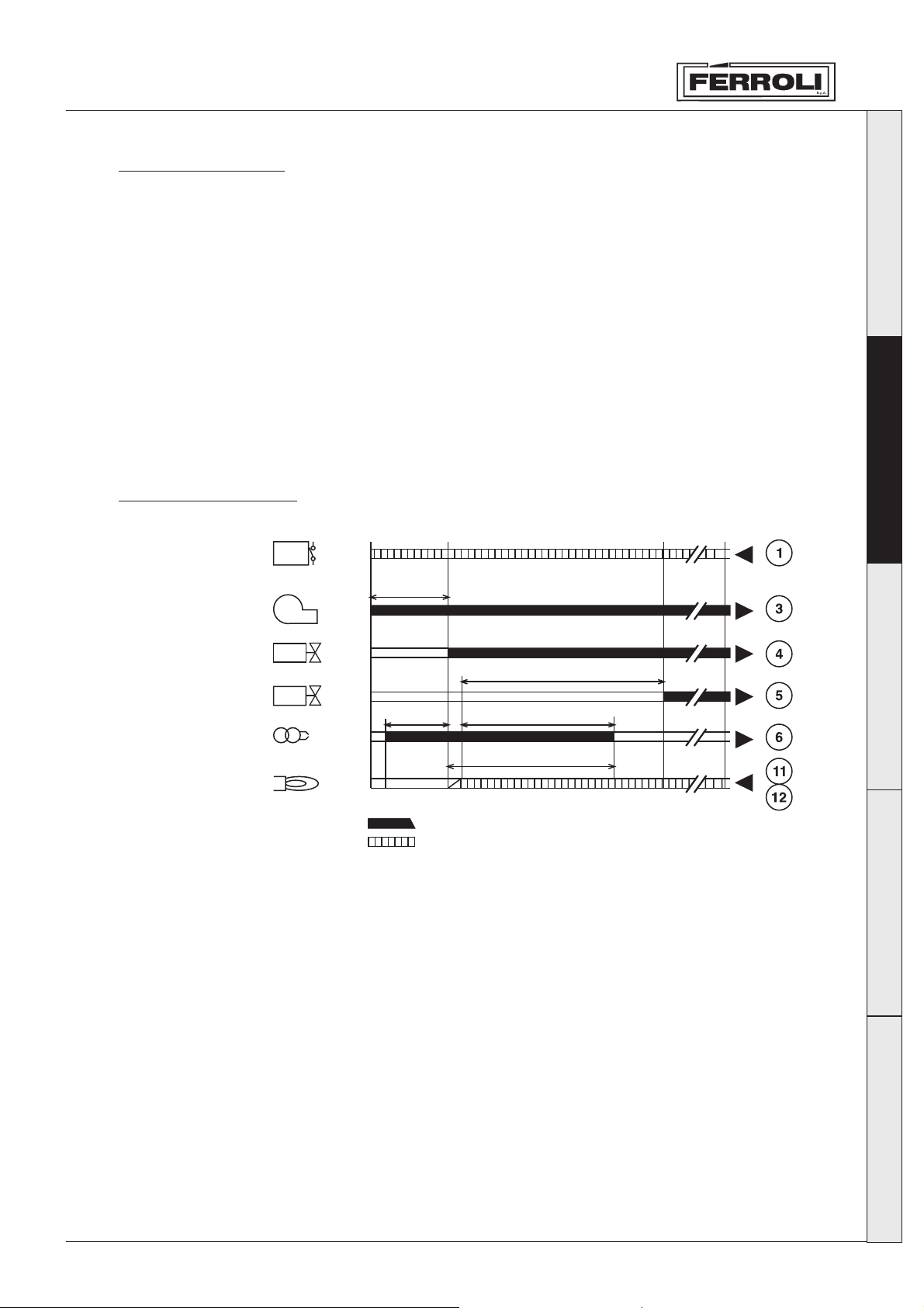
• Operation starts according to the diagram of fig. 9:
1 The burner motor will start turning, together with the pump: the oil fed in is completely sent to the
return. The ignition transformer is activated at the same time.
2 The following phases are performed: pre-ventilation of the furnace, pre-washing of part of the oil
circuit, pre-ignition, with discharge between the tips of the electrodes.
3 At the end of the pre-washing phase, the appliance opens the electromagnetic valve: the oil reaches
the nozzle, from where it is sprayed. Contact with the discharge between the electrodes ignites the
flame. At the same time, the safety time starts, within which the photo cell must detect the flame.
4 If the photo cell does not detect the flame, the burner shuts-down (the red light comes on).
Wait around 15 seconds, reset and repeat the ignition cycle.
Operating sequence
Thermostats
motor
1st-stage
solenoid valve
2nd-stage
solenoid valve
Ignition
transformer
Photo-cell
AB CD
R
W
SB
t1
M
BV1
t4
BV2
t3
Z
FS
t3n
TSA
Italiano
English
Français
Output signal
Input signal request
fig. 9
Key
A Start of commissioning for burners with no pre-heater
B Flame ignition time
C Operation
D Stop for R adjustment
t1 Pre-ventilation time
t3 Pre-ignition time
t3n Time after ignition
t4 Interval between flame signal and BV2 supply
TSA Safety time on starting
Deutsch
Español
33
Page 14
Italiano
SUN G50 - G70
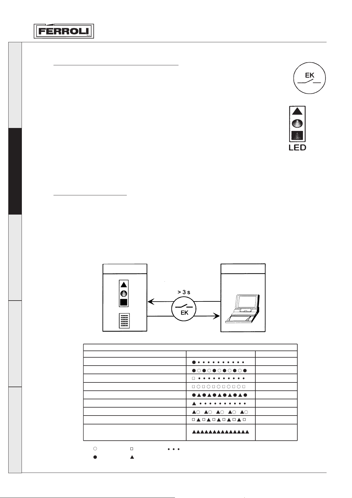
LMO24 fault-diagnosis and operation
The burner release button “EK” is used to reset the burner unit and to turn the faultdiagnosis functions on and off.
English
Français
The multicoloured LED is used for both types of fault diagnosis.
The “EK” button and the LED are located under the transparent cap of the release
Red
Yellow
button.
Green
Two types of fault diagnosis can be used.
1 Visual fault diagnosis - The burner’s operating status or the cause of the fault is
displayed.
2 Interface fault diagnosis - Using the OCI400 interface and the ACS400 software or a fume
analyzer.
Visual Fault Diagnosis
During normal operation, the various operating statuses are shown by the colour combinations as shown
in the table below.
Interface fault diagnosis is activated by pressing the burner release button for at least 3 seconds. If this
mode gets turned on accidentally, a weak red light starts blinking; to go back to the normal mode, just
press the Reset button again for at least 3 seconds.
The passage from one mode to the other is shown by the yellow LED blinking.
Operating position
Visual fault diagnosis
Operating position
PC/analyzer
interface
fault diagnosis
Deutsch
Español
Colour code table
Colour code table during the ignition phase
States Colour sequence Colours
Pre-ventilation
Ignition phase Blinking yellow
Operation, flame correct Green
Operation, flame defective Blinking green
Low voltage Yellow - Red
Foreign light in pre-ventilation
Fault diagnosis with interface
- Off
- Yellow
- Green
- Red
- Continuous
Yellow
RedShutdown
RedFault display (see fault table)
Green - Red
Weak red
LED blinking
34
Page 15
SUN G50 - G70
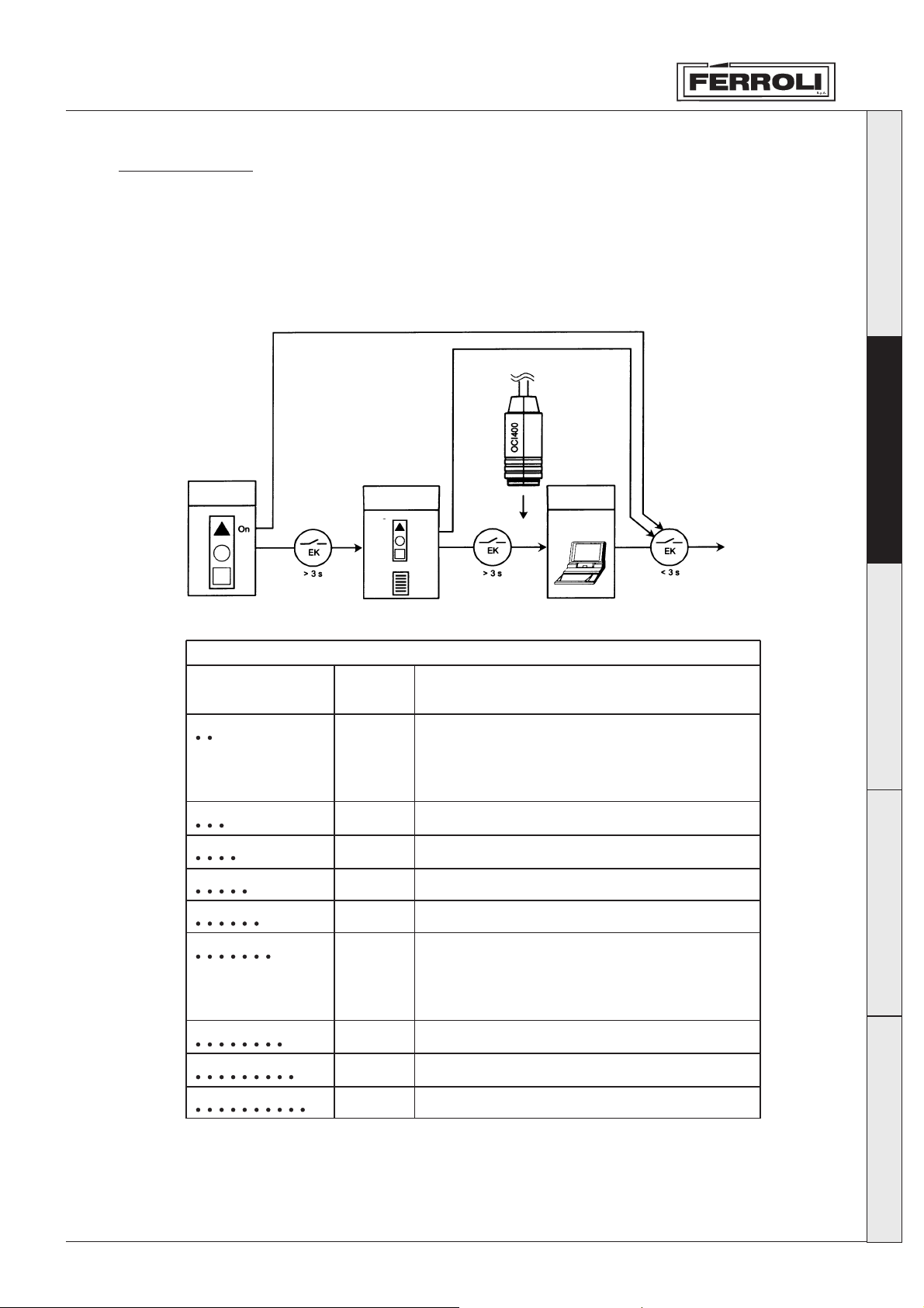
Fault table
Possible cause
2 blinks
3 blinks
4 blinks
5 blinks
6 blinks
7 blinks
8 blinks
9 blinks
10 blinks
Red light blinking
Free
Free
Faults with the wiring or inside the unit
Free
Free
Free
No flame during operation
1 fault with the fuel valves
2 fault with the photo-cell
3 no oil, wrong burner setting
No flame at the end of the safety time
1 fault with the fuel valves
2 fault with the photo-cell
3 no oil, wrong burner setting
Foreign light during pre-ventilation
“AL”
to the
terminal 10
On
On
On
On
On
On
On
On
Off
Fault Diagnosis
After shutdown, the red light stays on.
In this condition, after pressing the unit’s release button for at least 3 seconds, visual fault diagnosis is
activated (see fault tables).
On pressing the release button again for at least 3 seconds, interface fault diagnosis is activated .
Italiano
English
Shutdown
status
Shutdown
status
Visual fault diagnosis
Blinking
Fault codes
Shutdown
status
Opening
Français
Deutsch
During the check on the causes of the shutdown, the unit’s outputs are turned off.
The burner stays off.
Press the release button for approximately 1 second to reset the unit and restart the burner.
Español
35
Page 16
Italiano
SUN G50 - G70
Checks and adjustments during operation
• Connect a combustion analyser to the boiler outlet and operate the burner at full power for 10 minutes;
in the meantime, check the operation of the flue gas exhaust pipe.
• Slowly adjust the air damper until reaching the required excess air value for operation, using the
combustion analyser to check the O2 content in the flue gas. The O2 content in the flue gas should not
be less than 2.5% (risk of polluting combustion) and should not exceed 5% (risk of difficulty in ignition
and production of soot).
• Then perform a number of ignition cycles. In the event of flame pulsation or difficulty in igniting, adjust
the head, again using the combustion analyser to check the O2 content in the flue gas.
• Make sure that the pressure in the combustion chamber corresponds to the value indicated by the
manufacturer of the boiler
• Perform a complete analysis of the flue gas and check compliance with the limits set by the standards
in force.
3.3 Maintenance
English
Français
Deutsch
The burner requires periodic maintenance, to be performed at least once a year by authorised enabled.
The following basic operations must be performed:
• check and clean the internal parts of the burner, the tank and the boiler, as shown in the following
paragraphs;
• complete analysis of combustion (after normal operation for at least 10 minutes) and check the
adjustments are correct;
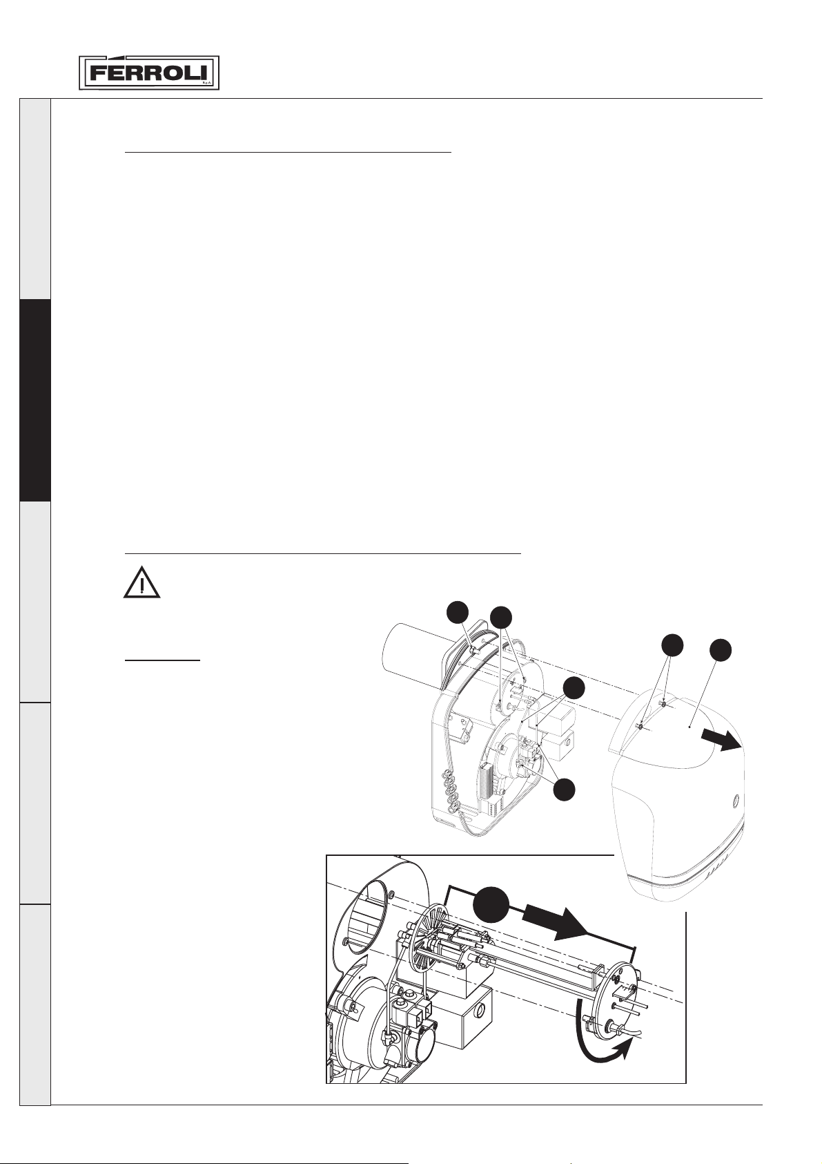
Opening the casing and removing the burner head
Before doing any cleaning or checking inside the burner, cut off the electricity supply to the
burner with the system’s main
switch. Shut off the fuel supply
too.
Sequence
• Unscrew the screws “A” and take off
the casing “B”. The internal
components, pump, motor, lock, etc.
are directly accessible.
• Unscrew the couplings “E” and extract
the copper tubes “F”.
• Slightly unscrew the two screws “D”,
turn and extract the combustion head
“G”.
• It is now possible to remove the burner
body too by simply
unscrewing the nut “C”.
C
D
A
F
E
B
Español
36
G
fig 11
Page 17

SUN G50 - G70
Checking the parts and components
Pump
The pressure must be stable at the value set during installation, and in any case between 10 and 14 bars.
No noise must be produced.
In the case of instable pressure or noisy pump, disconnect the flexible pipe from the line filter and feed
in the fuel from a tank located near the burner. This identifies whether the cause of the anomaly is the inlet
pipe or the pump.
Filters
Check and clean or replace, if necessary, the filters in the line, pump and nozzle.
If there is rust or other impurities in the pump filter, use a separate pump to remove water and other
impurities from the bottom of the tank.
Fan
Check that dust is not accumulated inside the fan and on the rotor blades: this reduces the air flow and
causes, as a consequence, polluting combustion.
Combustion head
Check that all the parts of the combustion head are intact, not deformed by the high temperatures, free
of impurities from the surrounding environment, and correctly positioned.
Nozzles
Avoid cleaning the hole of the nozzles, so as to not damage them
Replace the nozzles every 2-3 years, or when necessary. Combustion must be checked when changing the
nozzle.
Photo cell
Clean the glass for dust. The photo cell is pushed into place; to remove it, simply pull it out.
Flexible pipes
Check that they are in good condition, that they have not been stepped on or deformed.
Tank
Every 5 years or so, remove the water from the bottom of the tank using a separate pump.
Italiano
English
Français
3.4 Troubleshooting
Problem Possibile causes/
The burner does not ignite
During pre-ventilation, the
burner shuts down
The burner performs the preventilation and ignition cycle, but there is no flame and
the burner shuts-down.
Recommended solution
No electrical power /
Appliance shut-down/
Electrical devices defective/
Pump blocked/
Electric motor defective/
Electrical connections incorrect /
Photo cell short-circuited/
External light strikes the photo cell/
Electrical devices defective/
Oil valve defective/
No fuel in the tank, or water on the bottom/
Oil supply valve closed/
Filters dirty (line – pump - nozzle)/
Pump not primed/
Ignition electrodes poorly adjusted, or dirty/
Nozzle blocked, dirty or deformed/
Head and damper poorly adjusted/
Close the switches, check the fuses
Reset the appliance
Replace
Replace
Replace
Check
Replace the photo cell
Eliminate source of light
Replace
Replace
Open
Clean
Prime and look for cause of loss of prime
Replace
Adjust
Deutsch
Español
Top up fuel or remove the water
Adjust or clean
37
Page 18

SUN G50 - G70
Italiano
The flame is ignited normally,
but the burner shuts down at
the end of the safety time
Ignition with pulsating or disjointed flame, delayed ignition
English
Pump noisy, fluctuating pressure
Electrodes defective or earthed/
Ignition transformer defective/
Electrode cables defective or earthed/
Electrode cables deformed due to high temperature/
Electrical connections to the valve or transformer incorrect /
Defective appliance/
Motor-pump joint broken/
Pump inlet connected to the return pipe/
Photo cell defective/
Photo cell dirty /
Defective appliance/
Head poorly adjusted /
Ignition electrodes poorly adjusted or dirty /
Fan damper poorly adjusted, too much air /
Nozzle not suitable for the burner or the boiler /
Nozzle defective /
Pump pressure not suitable /
Air in the inlet piping /
Too much difference in height between the burner and the tank/
using a ring circuit and auxiliary pump
Pipe diameter too small /
Inlet filters dirty /
Oil supply valve closed /
Paraffin solidification due to low temperature /
Replace
Replace
Clean photo cell
Replace
Adjust
Replace
Tighten the fittings
Increase diameter
Clean
Open
Replace
Replace
Replace
Replace and protect
Check
Replace
Correct the connection
Adjust or clean
Adjust
See nozzle table
Adjust between min 10 and max 14 bars
Add additive to the oil
Supply burner
The pump loses prime after
extended shut-down
Français
Pump leaks oil
Fuel supply irregular
Bacharach soot dark
Deutsch
Bacharach yellow
Combustion head dirty
Return pipe not immersed in the fuel /
Air in the inlet piping /
Seal device leaking/
Supply system or pump blocked or defective /
located near the burner to identify whether the problem depends on the pump
or the system
Insufficient air /
Dirty or worn nozzle/
Nozzle filter dirty/
Incorrect pump pressure/
Flame stability disk dirty, loose or deformed /
Insufficient ventilation in the boiler room/
room, clean or enlarge
Excess air /
Head poorly adjusted or insufficient air /
Nozzle or nozzle filter dirty/
Incorrect nozzle angle or flow-rate/
Nozzle loose /
Impurities from the surrounding environment on the stability disk/
Adjust the head and fan damper
Adjust the head and fan damper.
Tighten
Tighten the fittings
Replace pump
Replace
Clean or replace
Adjust between min 10 and max 14 bars
Replace
Move to same height as the inlet pipe
Supply the burner from a tank
Clean, tighten or replace
Check ventilation openings in the
Adjust the head, open the air damper
Replace
Clean
Español
38
Page 19
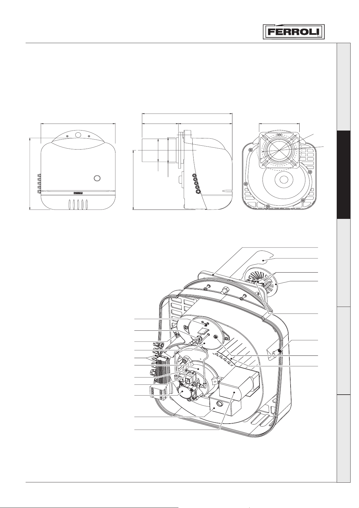
SUN G50 - G70
4. CHARACTERISTICS AND TECHNICAL SPECIFICATIONS
4.1 Dimensions
582
480
513
425
S.p.A.
4.2 Overall view and main components
235 347
fl165
fl181,4
fig. 12
260
fl290
fl225
19
Italiano
English
Français
Key
1 Adjustment head
adjustment screw
2 Photo-cell to check for
flame
3 Transformer
4 Cover for combustion head
inspection
5 Plugs for electrical
connection
6 Motor
7 1st-stage solenoid valve
8 2nd-stage solenoid valve
9 Pump
10 Unit
11 Servomotor for 1st-stage air
adjustment
12 Fan
13 Pressure test point
14 2nd-stage air adjustment
15 Ignition electrode
16 Combustion head
17 Nozzles
18 Nosepiece
19 Burner flange
20 Screw to secure burner to
flange
10
11
18
17
16
1
2
3
4
5
6
7
8
9
15
Deutsch
14
13
12
Español
fig. 13
39
Page 20
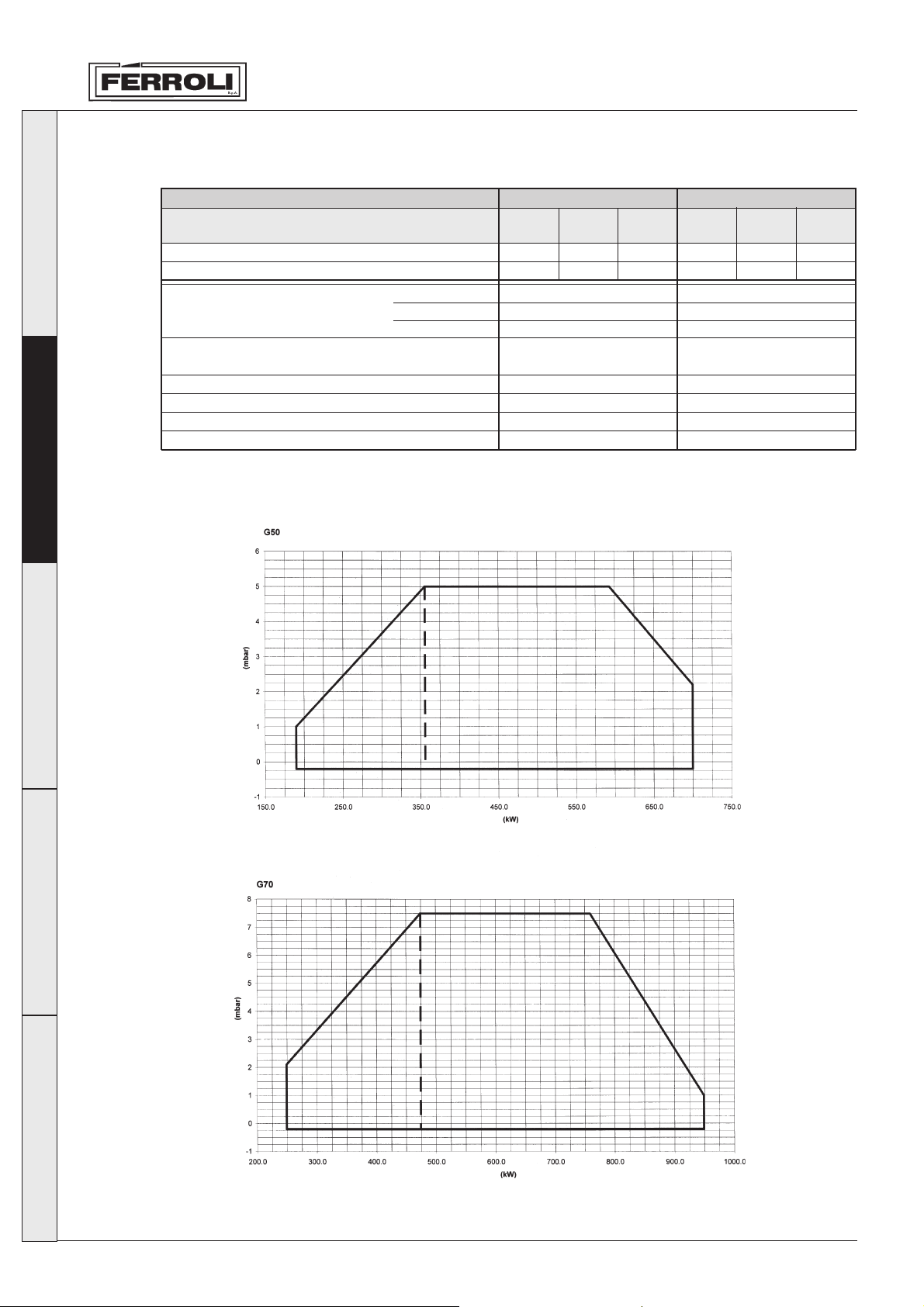
4.3 Table of technical specifications
SUN G50 - G70
Italiano
English
4.4 Operating field
Burner
Power
Flow rate
Hi
Fuel
Operation
Electrical power supply
Motor W
Power Input W
Protection rating IP
Diesel oil
Density
Viscosity at 20°C
kW
kg/h
kWh/kg
kg/dm
V/Hz
min.
1
st
stage
189,8 355,8
16 30
3
SUN G50
min.
nd
stage
2
11,86
0,82-0,85
1,5° E
Intermittent
twin-stage
400V 50HZ
1100
1150
40
max.
2nd stage
711,6
60
SUN G70
min.
1
st
stage
2nd stage
260,9 474,4
22 40
0,82-0,85
Intermittent
twin-stage
400V 50HZ
min.
11,86
1,5° E
1100
1150
40
max.
2nd stage
948,8
80
Français
Deutsch
Español
40
fig. 15
Page 21
SUN G50 - G70
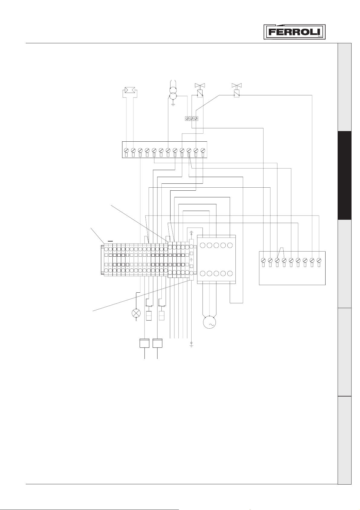
4.5 Wiring diagram
Weidmuller SAK 6/35
Weidmuller SAK 2,5/35
12
FR
11
10
TR
5
7
6
8
9
VE1
2
3
4
1
VE2
Italiano
LMO 44 Landys
English
A1
Français
123456789101112131415
LN
L3L2L
1L1 3L2 5L3 13NO
LC1 K1210 M7
1
LS
Weidmuller EAK 6/35
Key
CO1 1st-stage hour meter
CO2 2nd-stage hour meter
FR Photo-cell
LS Safety lamp
MB Burner motor
TR Ignition transformer
TS Safety thermostat
VE1 1st-stage electromagnetic valve
VE2 2nd-stage electromagnetic valve
SQN Servomotor
TC1 1st-stage thermostat
TC2 2nd-stage thermostat
N
W
CO2
N
T2
h
T1
W
h
CO1
N
LN
3L2L1
2L1 4T2 6T3 14NO
L
M
3
MB
A2
N8 41 35276
SQN 70.244A20
Deutsch
Español
41
 Loading...