

Page 1
INSTALLATION GUIDE
CITROËN
DS4
(MODEL B7)
REAR BRAKES
REAR BRAKES
TRW BRAKING SYSTEM WITH ELECTRIC PARKING BRAKE
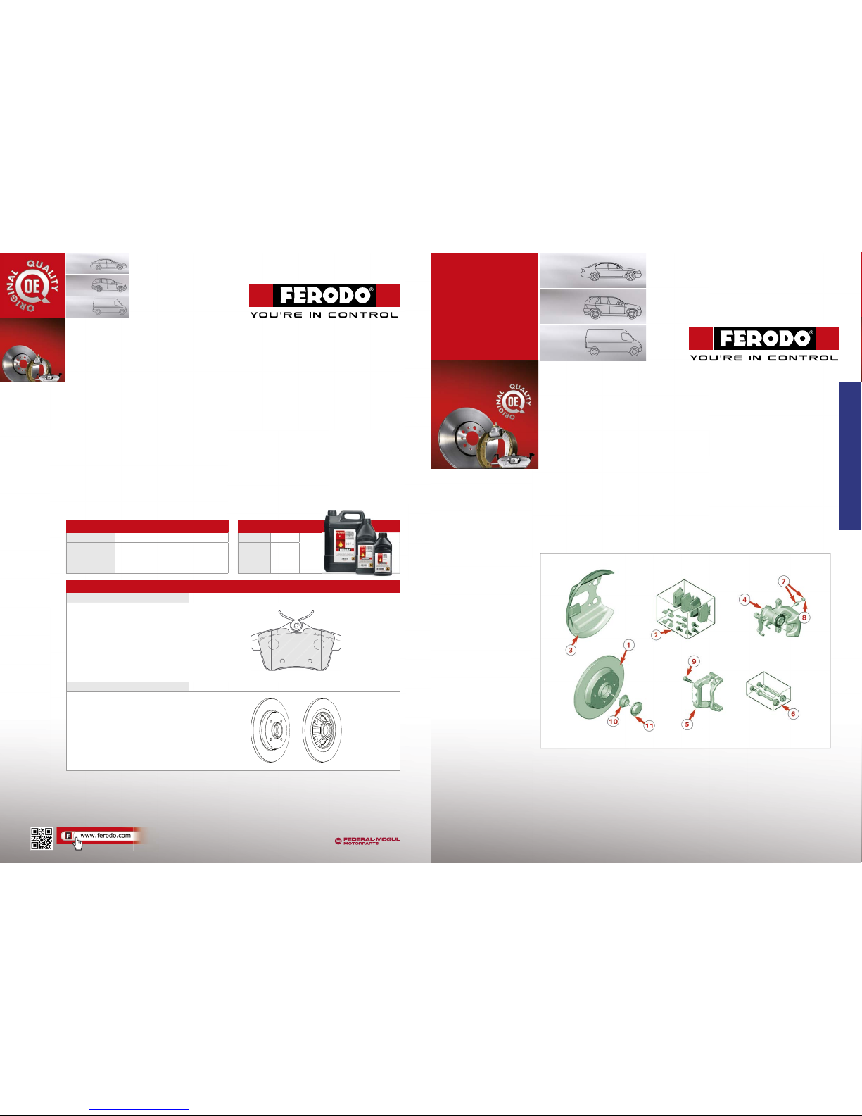
REAR BRAKE ASSEMBLY
1. Rear brake disc
2. Rear brake pads
3. Disc guard cover
4. Rear brake caliper
5. Brake caliper mounting bracket
6. Brake caliper slide pins
7. Bleeding screw
8. Caliper bleed screw cover
9. Caliper bracket mounting b olts
10. Bearing hub nut
11. Bearing hub cap
BRAKE FLUID
Product DOT 4
Capacity 1.0 litre
Maintenance
intervals
Replacement and bleeding
every 2 years
BRAKE FLUID DOT4
FBX050 500 ml
FBX10 0 1 lt
FBX500 5 lt
FBX2000 20 lt
Brake Pa d FDB4224
Length (mm) 103.8
Width (mm) 56.1
Thickness (mm)* 17.2
Thickness min (mm)* 8.00
Brake Di sc DDF1735
Diameter (mm) 268.00
Thickness (mm) 12.00
Min. thickness (mm) 10.00
Note: with bearing and ABS ring
* Backplate included
BRAKE FLUID
TOPPING UP AND BLEED ING
• Top up brake fl uid reservoir to the max. level.
• Use a transparent pipe on brake caliper bleedin g screw
respecting the following ble eding sequence:
1. Right hand rear wh eel
2. Le hand rear whee l
3. Right hand front wheel
4. Le hand front wheel
• Press brake pedal slowly to pressurise the brak ing circuit.
• Keep brake pedal pressed.
• Open blee ding screw (brake pedal lowers and
system press ure decreases).
• Keep pedal presse d all the way down and close
bleeding screw.
• Let pedal move up.
• Wait for 2 seconds to make brake fl uid reach brake
master cylinder.
• Repeat the op eration until brake fl uid is clean
and with no air bubbles.
FERODO PART NUMBERS
The Ferodo brand is a registered trademark of
Page 2
BRAKE PADS
REMOVAL
WARNING
If brake fl uid rese rvoir is at max.
level, remove fi lter an d partially
empty it using a clean syringe.
• Disengage parking brake.
• Disconnect battery negative terminal.
• Position vehicle onto li .
• Loosen wheel nuts and remove rear whe els.
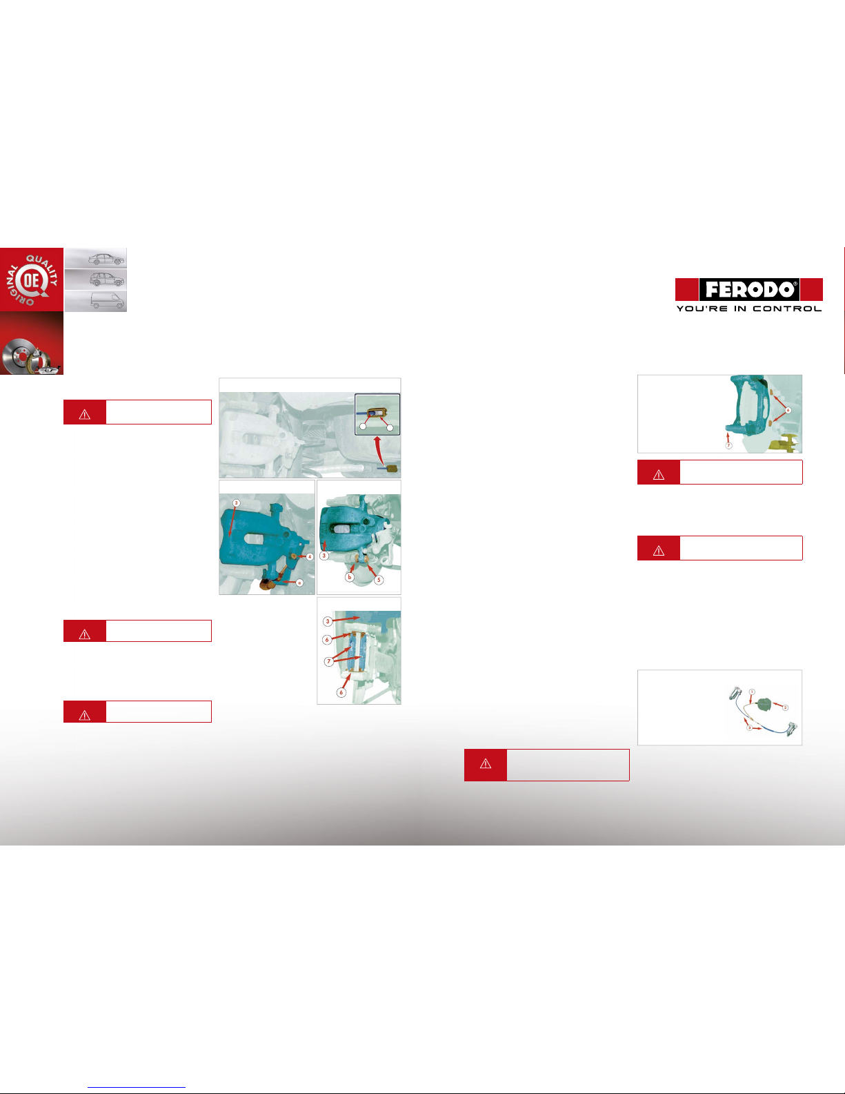
• Remove parking brake cable terminal
(1)
from bracket
(2).
• Remove parking brake cable terminal
(4)
from brake caliper
(3).
• Remove handbrake cable from calip er body
(a).
• Loosen lower screw
(5) with a wrench in point (b).
• Turn brake caliper
(3) up.
• Remove brake pads
(7) and pad abutment shims (6 ).
• Check bra ke pad wear evenness to detect any
caliper fault.
ASSEMBLY
• Visually ch eck sealing around brake caliper piston
and the conditions of protective caps.
• Turn clockwise and press b rake caliper piston
using a special tool to make it move back.
Remark: During this ope ration, visually check brake
fl uid inside rese rvoir to prevent any leakage.
WARNING
When changing bra ke pads, also
change brake pad abutment shims.
• Fit new pad abutment shims an d pads.
• Re-position br ake caliper and tighten the (new)
fastening bolts to a torque of 35 Nm.
• Refi t parking brake cable into original location.
• Fit rear wheels (and re-torque nuts) and remove
vehicle from li .
WARNING
Carry out the ope rations a er
battery re-connection.
• With engine r unning press brake pedal several times,
slowly and progressively until brake ped al feels fi rm.
• Check brake fl u id level and top up, if necessary.
• Adjust parking brake.
• Fill up and bleed braki ng system, if necessary.
BRAKE DISCS
REMOVAL
• Disengage parking brake.
• Disconnect battery negative terminal.
• Position vehicle onto li .
• Loosen fastening nuts and remove rear wheels.
• Remove brake pads (see dedicated procedure above).
• Remove fastening screw from brake caliper
hydraulic pipe fi tting.
• Remove bolts from slide pins between brake
caliper and caliper m ounting bracket.
• Remove the fastening bolts (6) between brake caliper
mounting bracket (7) and rear suspension .
• Visually check sealing around brake calipe r piston and the
conditions of protective caps.
• Turn clockwise to retract the caliper piston into the caliper
body using a special tool.
Remark: During this ope ration, visually check brake fl uid
inside reservoir to prevent any leakage.
• Tighten brake caliper hydraulic pipe fi tting screw to
manufactures torque.
ASSEMBLY
• Position brake disc with bearing onto rear bearing spindle
and tighten hub/bearing nut to the manufacturer’s torque.
• Position caliper mounting bracket onto rear suspension and
tighten the mounting bolts to manuf actures torque.
Brake caliper mounti ng bracket removal
WARNING
When changing bra ke pads, also change
pad abutment shims.
• Fit new brake pad abutment shims to the caliper bracket.
• Re-position brake caliper and tighten the (new) fastening
screw to a torque of 35 Nm.
• Re-attach parking brake cable.
• Fit rear wheels (and re-torque), remove vehicle from li .
WARNING
Carry out the ope rations a er battery
re-connection
• With engine running press brake pedal several tim es,
slowly and progressively until brake ped al feels fi rm.
• Check brake fl uid level and top up, if necessar y.
• Adjust parking brake.
• Fill up and bleed braking system, if neces sary.
ELECTRIC PARKING BRAKE
ADJUSTMENT
Remark: Electric par king brake can be adjusted only using a
diagnosis tester compatible with that of the ma nufacturer.
• Layout of parking brake cables.
• Calibrate parking brake (follow all the steps described
by the diagnosis tester).
• Read and delete any stored DTC.
• Operate park ing brake control and check that rear
wheels are safely locked.
WARNING
It is strictly forbid den to open an electric
parking brake assemb ly a er sale. If an
electric parki ng brake fault is detected,
the whole unit mus t be replaced.
Remark: In case of total system failure, such a s battery fault
or electric parking brake fault, system can be manually disengaged using the special tool supp lied with the vehicle tool kit.
Electric parking brake assembly
2
1
Parking brake cable remova l from bracket
Brake pad removal
Brake caliper cable removal
1. Primary cable
2. Electric parking brake unit
3. Electric parking brake
secondary cables
Remove lower screw
 Loading...