

Page 1
(VHI ADVANTAGE PRO) ADVANTAGE PRO HARNESS
USER INSTRUCTIONS
AdvantagePro Instructions: ID# 00152-V1- 08/2012
HARNESS DESIGNATION: FALL ARREST HARNESS
GENERAL USE: Safety harness for use in situations where there is a risk of free fall
SUGGESTED APPLICATIONS: Tower; Pole work; Rescue; Abseil
COMPLIANCE Complies with AS/NZ 1891.1
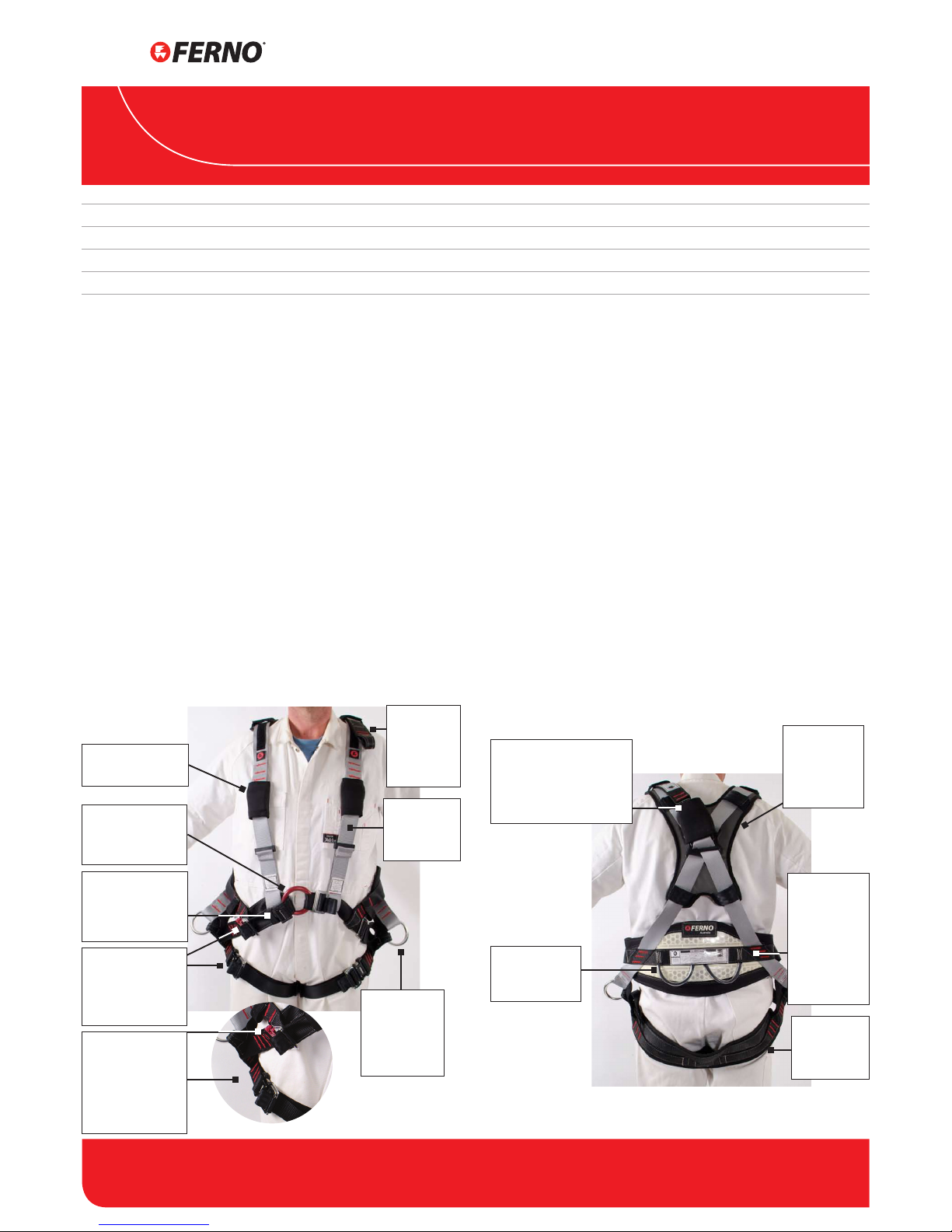
ATTACHMENT POINTS
Ensure you are familiar with all the attachment points on
this harness and their limitations. Each attachment point is
labelled appropriately.
Fall Arrest Attachment Points (refer notes on Energy Absorbers)
1. Rear dorsal D-ring is rated as a fall arrest attachment point
2. Extension strap on rear dorsal D-ring is rated as a fall
arrest attachment point
3. One front ‘O’ ring attachment point. Ensure you feed
adjustment male buckle (the one with the tongue)
through the back of the “O” ring and connect to the
female buckle.
Pole Strap Attachment Points
The large aluminium rings on the thighs are rated as Pole
Strap attachment points only. The connection rings must
be loaded equally with a pole strap as approved by Ferno
Australia. Do not connect to one ring only.
ENERGY ABSORBING LANYARDS
A Ferno energy absorbing lanyard must be used to connect
into a fall arrest attachment point. NOTE: The lanyard used
on the Dorsal Extension must not exceed 1.6 m in length.
FRONT VIEW OF HARNESS AND FEATURES
HEAD OFFICE: 11 Johnstone Road, Brendale, QLD 4500
Toll Free: 1800 804 647 | Tel: +61 7 3881 4999 | Email: sales@ferno.com.au | www.ferno.com.au
Australia
Adjustable straps
for centralising
Front Attachment
Point
Neoprene Buckle
Protector on chest
straps
Central Front Fall
Arrest/Rescue/Abseil Attachment
Point
Splash proof
and water
resistant
webbing
Rear Dorsal
Fall Arrest
Extension
Attachment
Point
Pole Strap
attachment
point on
either side of
harness
REAR VIEW OF HARNESS AND FEATURES
Rear Dorsal “D” Attachment Point with
extension and neoprene
protective cover
Rear Gear/
Equipment
Loops
Removable
Shoulder Pad
with reective grey
material
Wide onepiece leg
supporting
loops
Wide comfortable Waist
Belt with
reective
& photoluminescent
(glow-in-thedark) material
1
Front Fall Arrest
Attachment Strap
& Leg Strap Quick
Connect Buckles
Colour-coded
buckles:
RED = Front
adjustment buckle
BLACK = Leg strap
buckle
WARNING
1. A lanyard assembly should be secured to an anchorage
point that is at a level which will result in the minimum
free fall and the least total fall distance consistent with
the wearer’s ability to carry out work tasks. The maximum
allowable free fall is no more than 2 m.
2. Energy absorbers that absorb energy by permanent
deformation or destructive action should be discarded if
that process has commenced.
Page 2
AdvantagePro Instructions: ID# 00152-V1- 08/2012
2
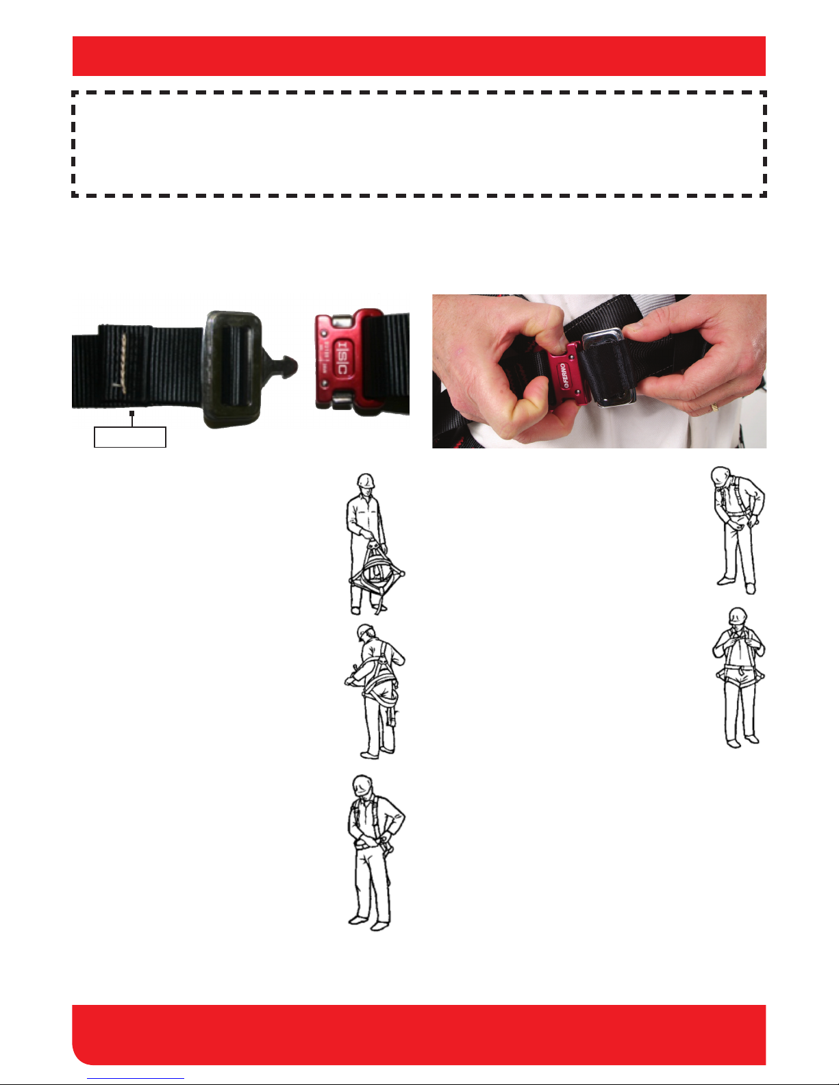
FITTING INSTRUCTIONS
INSPECTION
7. Pass both leg straps between your legs making
sure there are no twists in the straps. NOTE:
Leg strap quick connect buckles are black
coloured. Connect the left leg strap’s Quick
Connect buckle to the left leg link, and the
right leg strap to the right leg link. Adjust both
for a comfortable t.
Securing Quick Connect Buckles
To connect buckle, feed Male part into Female part of buckle
and listen for an audible click, ensuring the buckle is fastened
and secure.
Releasing Quick Connect Buckles
To release the buckle, simultaneously depress the tabs on
both sides of the female buckle and remove the male portion
of buckle.
MALE Buckle
Adjustment tail
FEMALE Buckle
Fitting the Harness
1. Read the instructions carefully and check the
harness labelling to ascertain that you have
the correct harness for the task.
2. Inspect the harness for signs of wear or
damage.
3. Hold up the harness by the rear D-ring and
untangle any straps that have twisted during
storage.
4. Separate the shoulder straps and familiarise
yourself with the layout of the harness.
Unhook the waist and leg buckles from their
respective links.
5. Put on the harness by passing your arms
through the shoulder straps as if putting on a
jacket. Adjust the shoulder buckles so that the
rear of the waist belt is level with your waist.
6. Connect the front fall arrest buckle by feeding
the quick connect buckle male tongue
through the front “O” ring closes to your body.
Clip to the female part of the red buckle and
adjust for a comfortable t. Check that the
rear D-ring is positioned centrally on your
back between your shoulder blades. If the
positioning is not correct, remove the harness
and slide the D-ring along the straps into the
desired position, and repeat Step 5.
8. Tighten and adjust the shoulder straps. Readjust the front fall arrest attachment strap
and leg buckles. The nished tting should feel
snug but not restrict movement in any way.
9. Secure loose ends with keepers and check for
twists, misaligned webbing and disconnected
buckles.
EMPLOYER: It is your responsibility to ensure all users are instructed and trained in the correct use and maintenance of the equipment. Once equipment is
issued, it is assumed this has been completed.
USER: Only competent users should use this equipment. It is your responsibility to read and understand these instructions and be properly trained in the use
of this equipment. Always use equipment safely and properly. Check equipment before and after each use
GENERAL: This document contains general tting instructions. Instructions are not all inclusive. Modifying the equipment can cause injury and damage and
will nullify any warranty and place full responsibility for any accident or injury on the equipment owner.
To maintain the safety and serviceability of this product, the
following inspections must be performed:
1. Operator Inspection
The operator shall inspect the product before and after
each use. Check for excessive wear or damage of all
webbing, thread, and metal components. Refer any signs of
deterioration to a competent person for a decision on the
safety and serviceability of the product.
WARNING: Harnesses and lanyard assemblies should be
destroyed or returned to the manufacturer for inspection if a
fall has been sustained.
Page 3

HEAD OFFICE: 11 Johnstone Road, Brendale, QLD 4500
Toll Free: 1800 804 647 | Tel: +61 7 3881 4999 | Email: sales@ferno.com.au | www.ferno.com.au
3
WARNINGS
Inspection (continued)
2. Periodic Inspection
A full periodic inspection shall be conducted every six months
by a competent person. Use the checklist shown below as a
guide for determining the condition of the product. Check for
any sign of contaminants such as oil, grease, paint, etc.
WARNING: If any part of an assembly is to be exposed to
chemicals, eg cleaning materials or hazardous atmospheres,
the user should consult the manufacturer to determine
whether the part is suitable for continued use. Periodic
inspections shall be recorded in the product’s Inspection and
Maintenance log.
CHECK LIST FOR INSPECTION OF HARNESSES, BELTS,
POLE STRAPS & LANYARDS
WEBBING
Cuts or tears
Abrasion damage, especially where there is contact
with hardware
Excessive stretching
Damage due to heat, corrosives or solvents
Deterioration due to rotting, mildew or ultraviolet
exposure
SNAP HOOKS &
KARABINERS
Distortion of hook or latch
Cracks or forging folds
Wear at swivels and latch pivot pin
Open rollers
Free movement of the latch over its full travel
Broken, weak or misplaced latch springs (compare if
possible with a new snap hook)
D-RINGS/ O-RINGS
Excessive vertical movement of the straight portion
of the D-ring at its attachment point on to the belt,
so that the corners between the straight and curved
sections of the D-ring become completely exposed.
NOTE: Excessive vertical movement of the ring in its
mounting can allow the nose of larger snap hooks to
become lodged behind the straight portion of the
D-ring in which position the snap hook can often
accidentally roll out of the ‘D” under load
Cracks, especially at the intersection of the straight
and curved portions
Distortion or other physical damage of the D-ring
Excessive loss of cross-section due to wear
BUCKLES &
ADJUSTERS
Distortion or other physical damage
Cracks and forging taps where applicable
Bent tongues
Open rollers
SEWING
Broken, cut or worn thread
Damage or weakening of thread due to contact with
heat, corrosives, solvents or mildew
ROPES
Cuts
Abrasion or fraying
Stretching
Damage due to contact with heat, corrosives,
solvents, etc
Deterioration due to ultraviolet light or mildew
Do not use this product until you have been trained by
a competent person and have read and understood the
following warnings in accordance with AS/NZS 1891.1.
1. Working at heights can be dangerous. If you use Ferno
equipment, you are responsible for learning and
observing safe techniques. Ferno Australia disclaims all
liability for any injury or loss arising from the use of this
equipment when its hardware, stitching or webbing is
frayed, damaged or in any way weakened by wear and
tear.
2. It is your responsibility to maintain the equipment in top
condition. This product is specically designed for height
safety and must not be used for other purposes.
3. You should be competent in the use of this lanyard
assembly before beginning any tasks requiring its use.
4. Do not make any alterations or additions to this product.
5. A lanyard assembly should be secured to an anchorage
point which is at a level which will result in the minimum
free fall and the least total fall distance consistent with
the wearer’s ability to carry out work tasks.
6. When making a connection to any point on a harness
which cannot be seen by the wearer of the harness, it
should either be made before putting the harness on, or
the connection should be made or checked for security
by a second person.
7. If any part of an assembly is to be exposed to chemicals
(eg. cleaning materials or hazardous atmospheres), the
user should consult the manufacturer to determine
whether the part is suitable for continued use.
8. Harnesses and lanyard assemblies should be destroyed
or returned to the manufacturer for inspection if a fall
has been sustained.
9. Energy absorbers that absorb energy by permanent
deformation or destructive action should be discarded if
that process has commenced.
10. This Harness should be subjected to regular maintenance
in accordance with Ferno Australia’s recommendations
and inspections at least every 6 months and withdrawn
from use if not deemed by a competent person to be
suitable for continued use.
11. The free tail on any twin tail lanyards must not be
back hooked to any point on the wearer, the wearer’s
equipment or the lanyard below the bifurcation other
than a point specically provided by Ferno Australia for
that purpose.
12. The Ferno Australia Energy Absorbing lanyard is
designed to limit the shock sustained during a fall to
6.0kN. You should never use a harness in a fall arrest
situation without using an energy absorbing lanyard.
13. If you are not sure whether this product is suitable for
your application, refer to: AS/NZS 1891.4 - Selection use
and maintenance.
WARNINGS
Page 4

HEAD OFFICE: 11 Johnstone Road, Brendale, QLD 4500
Toll Free: 1800 804 647 | Tel: +61 7 3881 4999 | Email: sales@ferno.com.au | www.ferno.com.au
4
MAINTENANCE & STORAGE
Maintenance
This product should be cleaned regularly to maintain its safety
and serviceability. Clean as indicated below:
1. After each use
After each use, wipe down the product to remove any dust
or dirt. If there is any sign of contaminants such as oil, grease,
paint etc., Tag the product as unt for use and refer it to a
competent person for inspection.
WARNING: If any part of an assembly is to be exposed to
chemicals (eg: cleaning materials or hazardous atmospheres),
the user should consult the manufacturer to determine
whether the part is suitable for continued use.
WARNING: Harnesses and lanyard assemblies should be
destroyed or returned to the manufacturer for inspection if a
fall has been sustained.
2. During Periodic Inspection
Hand wash the product with Ferno Rope & Harness Wash
every alternate periodic inspection (ie: every twelve months).
Do not machine wash. Hang the product in a shaded area,
away from direct heat, to dry completely. Do not tumble dry
or put into storage until fully dry. Refer to the manufacturer for
advice on removing dicult stains.
Storage
Store the product away from direct sunlight, excessive dust
and moisture and corrosive atmospheres.
SUPPLIER
DESIGNATION Fall Arrest Harness
MODEL/ITEM # VHI Advantage Pro MANUFACTURE DATE
SERIAL # PURCHASE DATE
BATCH # COMMISSIONED DATE
INSPECTION AND MAINTENANCE RECORD
DAT E NAME DETAILS
 Loading...