

Page 1
User and
Maintenance Manual
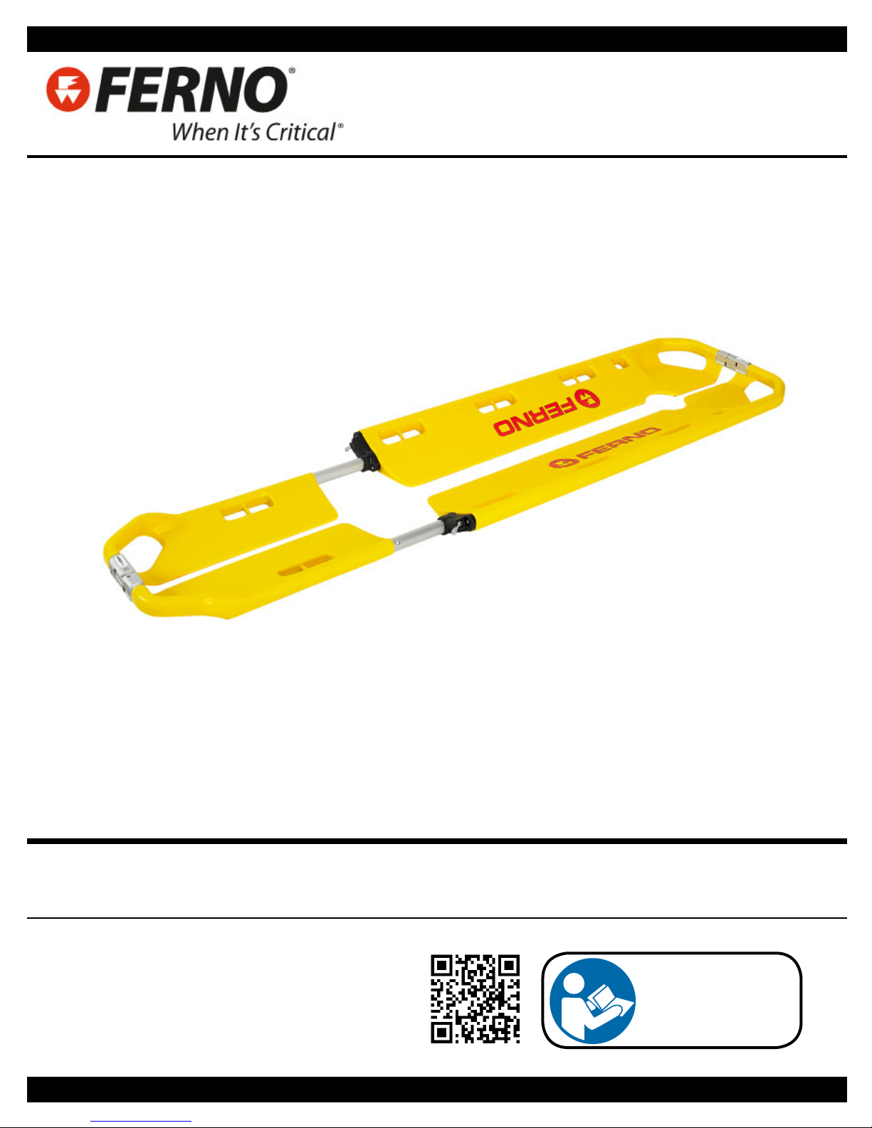
SCOOP EXL Atraumatic Stretcher
Rel.161115
English (UK)
Read this manual
carefully and keep it
for future reference.
Page 2
Ferno Technical Support
Customer Service and Technical Support are important aspects of
every Ferno product. Before contacting us, please record the serial
number of the product and specify it in all written communications.
For all queries concerning technical support, contact Ferno
Washington Italia s.r.l.:
Telephone (toll-free, Italy only) 800 501 711
Fax +39 0516861508
Email info@ferno.it
Ferno Customer Service
For assistance and further information, contact Ferno Washington
Italia s.r.l.'s Customer Services:
MANUFACTURER
Ferno Washington Italia s.r.l., Via Benedetto Zallone 26
40066 - Pieve di Cento (BO) - ITALIA
Telephone (toll-free in Italy) 800 501 711
Phone +39 0516860028
Fax +39 0516861508
Website www.ferno.it
SCOOP EXL Stretcher
USER AND MAINTENANCE MANUAL
To request additional free copies of the
instruction manual, please contact Ferno
Washington Italia's Customer Services.
Limitation of liability
This manual contains general instructions on the use and
maintenance of the product. The instructions do not cover all the
possible applications and operations. The user is solely responsible
for proper and safe use of the product. The safety information is
provided as a service to the user and ensures only the minimum
required level of safety to prevent injury to operators and patients.
Any other safety measure implemented by the user must comply
with applicable regulations. Before using the product, it is strongly
recommended that sta be trained in its correct usage. Retain
this manual for future reference. In case of change of ownership,
ensure that the manual remains with the product. Additional free
copies can be obtained from Ferno Washington Italia's Customer
Services.
Declaration of ownership
The information in this manual is the property of Ferno Washington
Italia s.r.l. of Via Benedetto Zallone 26, 40066 Pieve di Cento
(BO), Italy.
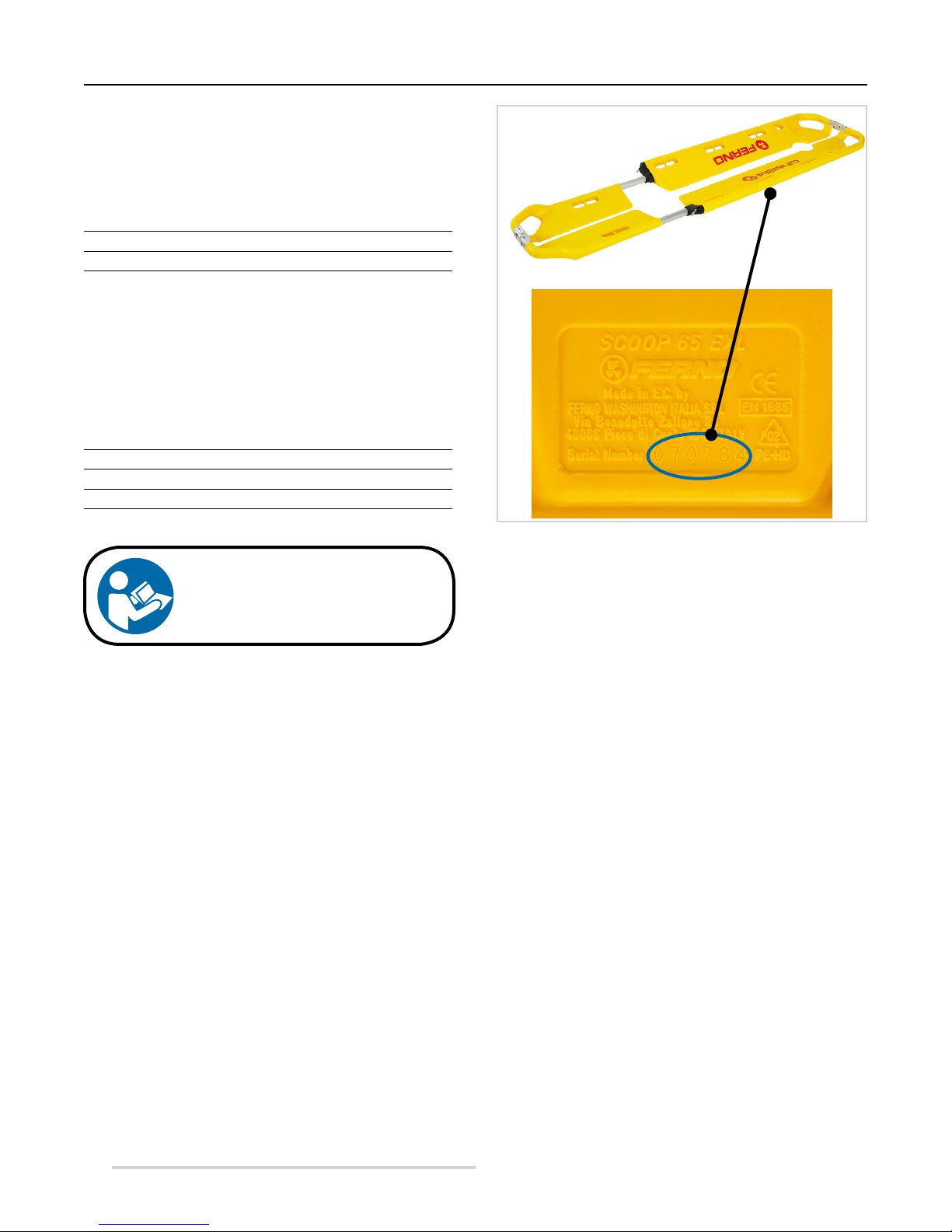
SCOOP EXL Serial No. ________________________
Location: Rear of the body section, on the right side when
viewed by operator.
All patent rights, and rights relating to the design, construction,
reproduction, use and sale of any item covered in this manual are
condential and the sole property of Ferno Washington Italy s.r.l.,
with the exception of rights expressly transferred to third parties
or not attributable to parties owned by the supplier. It is prohibited
to reproduce this manual, either in full or in part, without the prior
consent of Ferno Washington Italia s.r.l..
Disclaimer
The products sold by Ferno are covered by a 24-month warranty
against manufacturing defects. For the full terms and conditions of
warranty and liability, see Chapter 9 Warranty, page 32.
© Copyright Ferno Washington Italia s.r.l. All Rights Reserved.
2
© Ferno Washington Italia ScoopExl - Rel.161115 - ENG
Page 3

SCOOP EXL Stretcher
CONTENTS
Chapter/Section Page Chapter/Section Page
Ferno Technical Support _______________________ 2
Ferno Customer Services ______________________ 2
1 - Safety Information __________________________ 4
1.1 Warning ________________________________ 4
1.2 Important _______________________________ 4
1.3 Blood-borne diseases ______________________ 4
1.4 Load capacity ____________________________ 4
1.5 Compatibility ____________________________ 4
1.6 Symbol glossary __________________________ 5
1.7 Information and safety labels ________________ 5
2 - Operator training and skills __________________ 6
2.1 Skills ___________________________________ 6
2.2 Training ________________________________ 6
3 - The Stretcher _______________________________ 6
3.1 Description ______________________________ 6
3.2 CE conformity ___________________________ 6
3.3 Components (Stretcher) ____________________ 7
3.4 General Specications _____________________ 8
4 - Conguring the stretcher _____________________ 9
4.1 Adjusting the length _______________________ 9
4.2 Twin Safety Lock (TSL) System ____________ 10
4.3 How to fold the stretcher____________________11
4.4 How to extend the stretcher ________________ 12
4.5 Lifting handles __________________________ 12
4.6 Lateral holes ____________________________ 12
4.7 Pins ___________________________________ 12
5 - Using the stretcher _________________________ 13
5.1 Before using the stretcher __________________ 13
5.2 Usage instructions _______________________ 13
5.3 Attaching the restraints ____________________ 14
5.4 Immobilizing the patient __________________ 15
5.5 Tilting the patient ________________________ 22
5.6 Lifting and transporting ___________________ 25
5.7 Additional help __________________________ 26
6 - Maintenance ______________________________ 27
6.1 Maintenance ______________________________ 27
6.2 Disinfection ____________________________ 27
6.3 Cleaning _______________________________ 27
6.4 Inspection ______________________________ 28
6.5 Lubrication _____________________________ 29
6.6 Inspecting and locking coupling pins _________ 29
6.7 Storage ________________________________ 30
7 - Accessories ________________________________ 31
7.1 Accessories for SCOOP EXL stretcher __________ 31
7.2 EXL SCOOP Stretcher Models ________________ 31
7.3 Patient restraints ____________________________ 31
8 - Technical assistance ________________________ 31
8.1 Technical Support Service ___________________ 31
9 - Warranty _________________________________ 32
9.1 Warranty Terms & Conditions ______________ 32
9.2 Limitations of liability ____________________ 32
9.3 Warranty Claims _________________________ 33
9.4 Complaints _____________________________ 33
9.5 Returns authorization _____________________ 33
Bibliography _________________________________ 34
Training record ______________________________ 35
Maintenance record ___________________________ 36
© Ferno Washington Italia ScoopExl - Rel.161115 - ENG
3
Page 4

Safety information
SCOOP EXL Stretcher
1 SAFETY INFORMATION
Read the user manual carefully It is an integral part of the
product and must always be kept to hand. For your own
personal safety and that of your patients, please note the
following:
– Prior to each use, perform an inspection ensuring that
there are no signs of wear, damage, or malfunction. Refer to
section 6.4 Inspection, page 28.
– To prevent infection and / or bacterial contamination, refer
to the information in sections 6.2 and 6.3, Disinfection and
Cleaning, page 27.
1.1 Caution
The danger symbols draw attention to potentially dangerous
situations that, if ignored, may result in accidents, damage
and/or injury.
WARNING
Untrained users may injure themselves and/or cause damage and/
or physical harm. Allow only trained and qualied sta to use the
SCOOP EXL stretcher.
Improper use of the stretcher can cause damage and / or injury. Use
the SCOOP EXL stretcher as described herein.
Unauthorized modications to the SCOOP EXL stretcher can cause
serious damage, injury and / or unpredictable problems. Do not
modify or alter the stretcher in any way.
Any damage to the components of the stretcher or the entire
system can alter its performance and safety. Inspect the SCOOP EXL
stretcher frequently, and especially before and after each use. Place
the stretcher out of service if there are signs of wear or damage.
An unassisted patient is at risk of injury. Never leave the patient
alone when bound to the stretcher. Always assist the patient
throughout all rescue operations.
Failure to use the restraints can cause the patient to fall and
endanger their safety. Always use the containment restraints for the
patient as indicated herein.
Applications of the stretcher restraints that are not as described in
this manual could cause accidents, damage and / or injury.
Casual assistants may cause damage and/or physical harm, or
injure themselves. Do not allow casual helpers to perform stretcher
preparation operations. Be extremely careful during all user
operations.
Improper maintenance can cause serious accidents, injuries and/or
damage. Perform maintenance as instructed in this user manual.
The use of improper and/or unauthorised devices can cause
accidents, damage and/or injury. Use only devices that have been
approved and authorised by Ferno Washington Italia.
WARNING
Unauthorised repairs, and repairs carried out by people not
approved by Ferno Washington Italia, will render all warranties
null and void and may compromise the safety of the device.
Non-original spare parts and inadequate repairs may cause
damage and/or injury. Use original Ferno parts exclusively, and
only contact Ferno Washington Italia's Customer Support.
1.2 Important
Boxes labelled "Important" contain important
information on use and/or maintenance of the device.
Important
1.3 Blood-borne diseases
To reduce the risk of exposure to infectious diseases that
may be transmitted by blood, such as HIV-1 or Hepatitis,
carefully follow the instructions on disinfection and cleaning
in this manual.
1.4 Load capacity
Respect the maximum loading capacity of the SCOOP EXL
stretcher. Refer to section 3.4 General specications, page
8.
1.5 Compatibility
Use only accessories approved and authorized by Ferno.
The SCOOP EXL stretcher was tested with the following
accessories which are applied during immobilization:
– 365-E Immobilizer (code 365-E)
– WizLoc Cervical Collar (code 0822074)
- restraint systems (listed in section 7.3 Patient restraints,
page 31).
The stretcher supports the use of the SAERBAG III fabric
lifting and transport system, and the paediatric PEDISLEEVE immobilization device.
Any other combination is not compatible with the
specications and instructions given in this manual. Ferno
Washington Italia is not liable for damages caused to users
or third parties arising from improper use of the SCOOP
EXL stretcher.
4
© Ferno Washington Italia ScoopExl - Rel.161115 - ENG
Page 5
SCOOP EXL Stretcher
Safety information
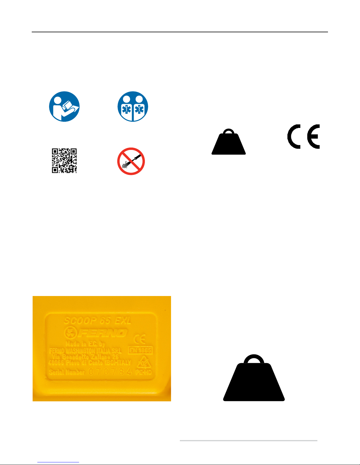
1.6 Glossary of symbols
The symbols used in this manual and / or on the stretcher's labels are dened below. The CE mark is present on the stretcher
and in this manual.
2
Read the user manual
carefully
QR Code
The stretcher requires at
least two qualied operators
for correct use
Do not wash with high
pressure water
227 kg
500 lb
36 st
Load capacity
(in kilograms, pounds, and
stones)
The product meets
European Union
Standards
1.7 Information and safety labels
The information and safety labels contain important information that the user needs to know.
Read and follow label instructions. Immediately replace the labels if they are worn or damaged. To obtain replacement labels
contact Ferno Washington Italy's Customer Services (page 2).
The Manufacturer reference numbers, the CE mark, and the serial number, are on the rear of the stretcher (on the right side
of the body as seen by the operator).
Main label Load capacity (in kilograms, pounds, and stones)
© Ferno Washington Italia ScoopExl - Rel.161115 - ENG
SWR
Never exceed the load capacity of the SCOOP EXL stretcher. Inspect
the stretcher if the carrying capacity has been exceeded (see section
Inspection).
SWR- Strength to Weight Ratio = 28.4
Safety factor = 2
227 kg
500 lb
36 st
5
Page 6

Training / The Stretcher
SCOOP EXL Stretcher
2 TRAINING AND RESPONSIBILITIES OF OPERATORS
2.1 Skills
Operators who use the stretcher must:
● have specic experience in immobilization, handling,
and recovery of patients.
● possess the appropriate skills to assist the patient.
2.2 Training
Users are required to:
● Read and understand all information in this manual.
● Attend a suitable training course on the use of the
stretcher.
● Practice with the stretcher before using it in real
situations with patients.
3 THE STRETCHER
3.1 Description
The atraumatic SCOOP EXL stretcher (known as the
"stretcher" in this manual) is a device made for the aid,
immobilization and transport of the patient. The stretcher
should be used only by trained and qualied sta. Any
additional assistance needed to handle heavy patients and/
or when the situation demands it must always comply with
applicable healthcare protocols.
The stretcher can be adjusted in length according to the
height of the patient up to 2100 mm. It can be folding away
by placing the foot section within the body section, and can
be divided into two or four parts for storage (see section 6.7
Storage, page 30).
From serial number S/N 30001, the SCOOP EXL stretcher
has been built with non-ferromagnetic metal components so
that it can be used in magnetic elds with values no greater
than 1.5 T. The eld test carried out on the stretcher (model
65EXL-NM) exposed to a magnetic eld with values up to
1.5 T, produced the following results:
- the device suered no stress in any of the elds;
- no eddy currents were detected while the device was
moved within the elds;
- there were no appreciable temperature changes over the
patient contact areas (all below 35° C) of the stretcher in
any of the elds;
● log the training sessions. An example of a form for
logging the training sessions can be found on page 35.
WARNING
Untrained users may injure themselves and/or
cause damage and/or physical harm. Allow only
trained and qualied sta to use the SCOOP EXL
stretcher.
Important
The operators must be able to ensure the safety of
both themselves and their patients while using the
stretcher. They must be able to assess the number
of people needed to move the patient according to
applicable regulations.
- imaging is possible without any problems and without any
registered artifacts;
- a complete thermograph immediately subsequent to the
imaging revealed no changes in the stretcher's temperature.
3.2 CE compliance
MEDICAL DEVICES DIRECTIVE
Ferno's products meet the requirements of
European Directive 93/42/EEC concerning
medical devices.
For more information: www.ferno.it
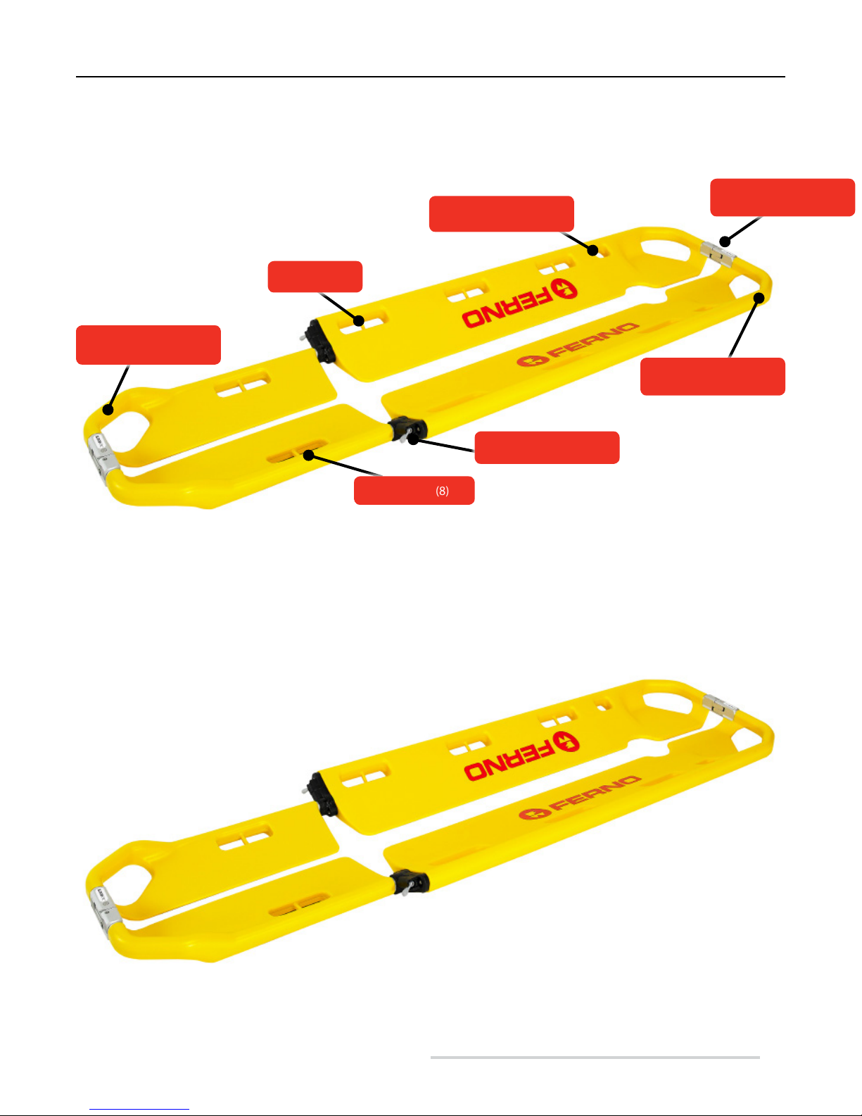
STRETCHER COMPONENTS
● Lifting handles (2 at the head end, 2 by the feet)
● Side handles (8, 4 on each side): each handle has a pin
inside for attaching the restraint hook.
● Small side holes (2) for fastening the "H"-shaped
Velcro band for the 365-E head immobilizer
● TSL Twin Safety Lock coupling systems (2). Each
TSL is tted with buttons to open the stretcher.
● Side locking handles (2) for adjusting the length of the
stretcher
● Pin for attaching the restraint hooks (8)
6
© Ferno Washington Italia ScoopExl - Rel.161115 - ENG
Page 7
SCOOP EXL Stretcher
3.3 Components (Stretcher)
Pins (8)
Lifting handles, foot end
(2)
Small side holes (2)
Locking handles (2)
Stretcher
HEAD
END
Lifting handles, head end
Twin Safety Lock (2)
(2)
FOOT
END
FOOT SECTION
Side holes (8)
HEAD
END
BODY SECTION
FOOT
END
© Ferno Washington Italia ScoopExl - Rel.161115 - ENG
7
Page 8
Stretcher
SCOOP EXL Stretcher
3.4 General Specications
Ferno reserves the right to change the specications without
notice. For more details, please contact Ferno's Customer
Service (page 2).
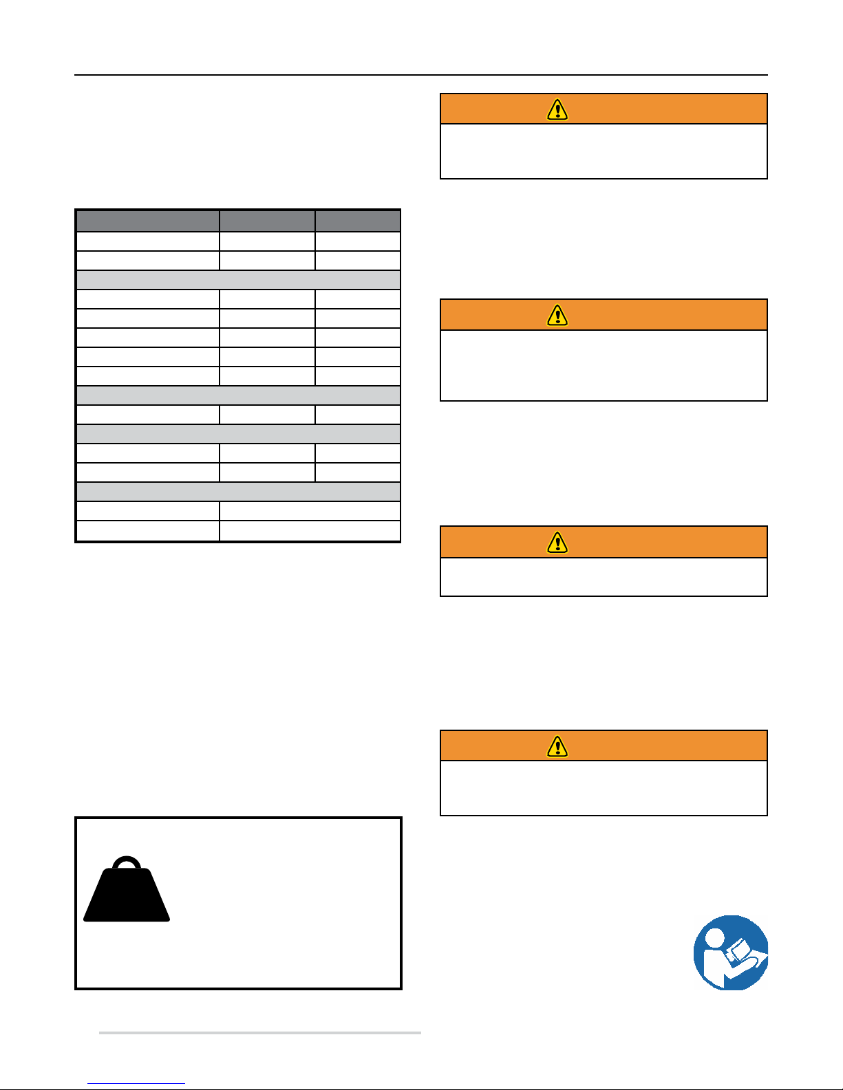
Specications
Load capacity 350 lbs 227 kg
Weight 17.64 in 8 kg
Length
Folded 47.24 in 1200 mm
Position 1 64.84 in 1647 mm
Position 2 69.68 in 1770 mm
Position 3 74.41 in 1890 mm
Position 4 79.13 in 2010 mm
Width
Total 17 in 432 mm
Width
Open 2.76 in 70 mm
Folded 3.15 in 80 mm
Materials
Structure HDPE
TSL stainless steel
WARNING
Improper use of the stretcher can cause damage
and / or injury. Use the SCOOP EXL stretcher as
described herein.
WARNING
Untrained users may injure themselves and/or
cause damage and/or physical harm. Allow only
trained and qualied sta to use the SCOOP EXL
stretcher.
WARNING
Never exceed the load capacity of the stretcher as
specied in this manual.
Load capacity
Never exceed the load capacity of
227 kg
500 lb
36 st
SWR- Strength to Weight Ratio = 28.4
Safety factor = 2
8
the SCOOP EXL stretcher. Inspect
the stretcher if the carrying capacity
has been exceeded (see section 6.4
Inspection, page 28).
WARNING
Never connect lifting devices directly to the
stretcher's pins. The pins are intended solely for
connecting the restraint hooks.
USER AND MAINTENANCE MANUAL
To request additional free copies of the
instruction manual, contact Ferno Washington
Italia Customer Service (page 2).
© Ferno Washington Italia ScoopExl - Rel.161115 - ENG
Page 9
SCOOP EXL Stretcher
4 STRETCHER CONFIGURATION
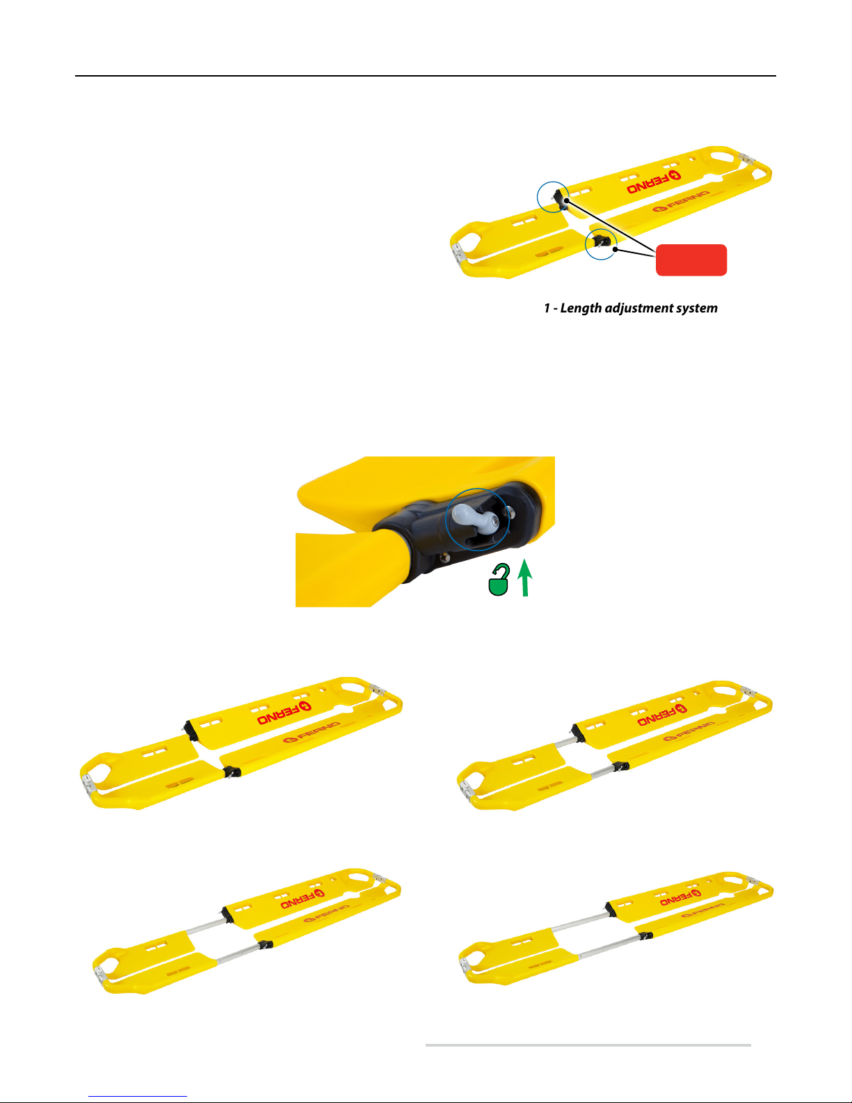
4.1 Adjusting the length
The length of the SCOOP EXL stretcher is adjustable
(4 positions). This adjustment allows the stretcher to be
adapted to the height of the patient.
When preparing the stretcher, adjust its length so that it is
properly adapted to the height of the patient.
Stretcher conguration
Locking
handles
ADJUSTING THE LENGTH
To adjust the stretcher length, proceed as follows:
1. Release the locking levers on both sides of the stretcher, positioning them facing upwards (Figure 2).
2. Pull out the foot section to the desired length. The stretcher can be locked in 4 dierent lengths, corresponding with the holes
in the tubular part of the foot section (Figure 3A, 3B, 3C, 3D). While adjusting the length it is recommended to keep the two
parts that make up the stretcher attached.
Figure 2 - Locking handles facing up: STRETCHER
UNLOCKED
Figure 1 - Length adjustment system
Figure 3A - Position 1
Figure 3C - Position 3
© Ferno Washington Italia ScoopExl - Rel.161115 - ENG
Figure 3B - Position 2
Figure 3D - Position 4
9
Page 10
Stretcher conguration
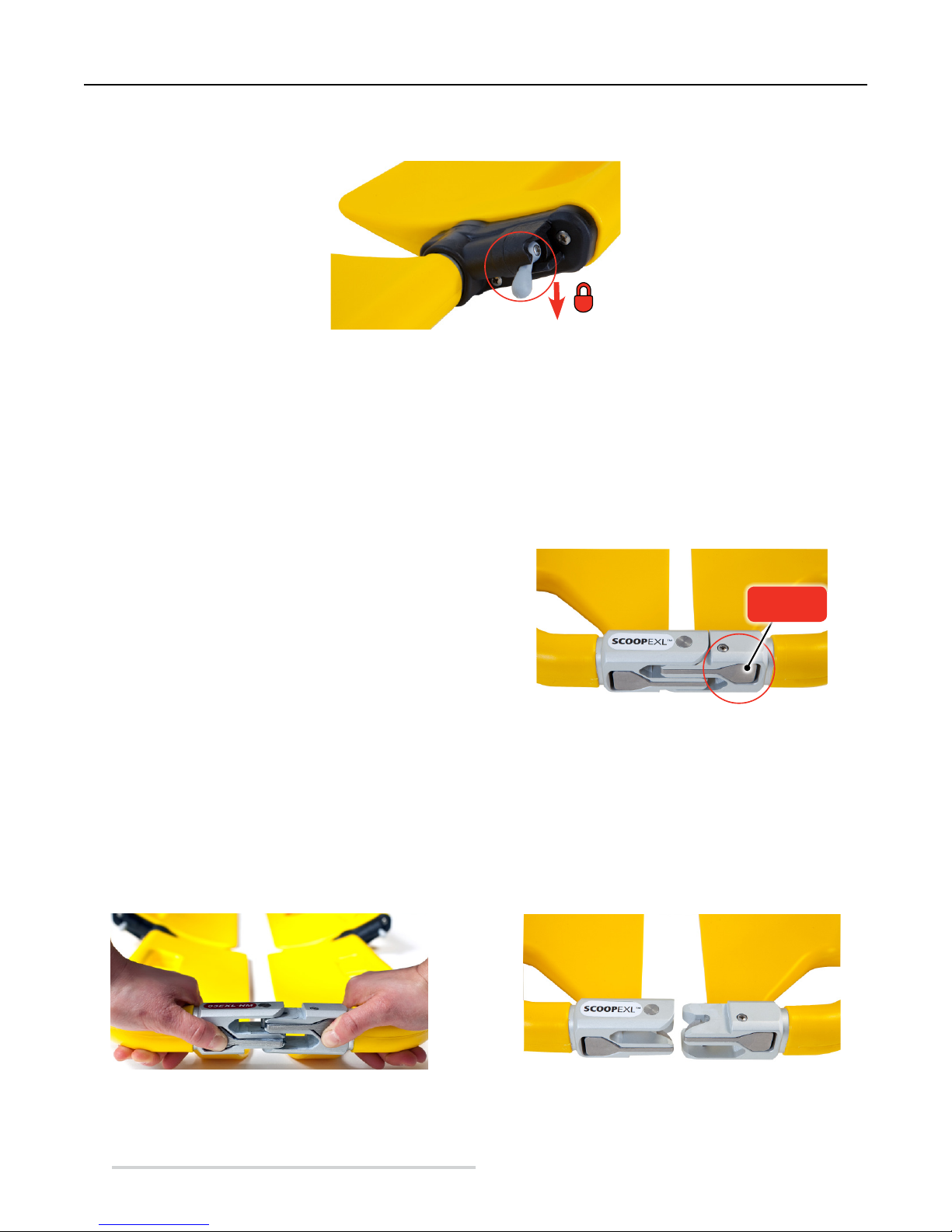
3. After reaching the desired length, lock the levers on both sides of the stretcher, positioning them facing downward (Figure
4). When correctly aligned, an audible click is heard.
Figure 4 - Locking handles facing down: STRETCHER LOCKED
4.Ensure the adjustment was successful and that the length of the stretcher is set according to the height of the patient.
5. Before any use of the stretcher, ensure the latches are locked (facing downward, Figure 4) and that the stretcher is properly
locked into position.
After appropriately adjusting the length of the stretcher, check the locking levers are set correctly. To verify, check that both
levers are pointing downwards, then pull out the foot section. If the section does not extend, the latches are locked correctly
and the stretcher is locked in position.
SCOOP EXL Stretcher
4.2 Twin Safety Lock (TSL) System
The stretcher is tted with two Twin Safety Lock (TSL)
systems that allow you to open or close the stretcher
lengthwise, splitting it into two equal parts (Figure 5).
The two TSL systems are positioned at each end of the
stretcher (head end and foot end) and each has two buttons
for the opening of the stretcher.
Figure 5 - Twin Safety Lock (TSL) System
HOW TO OPEN THE STRETCHER
Each TSL consists of two buttons (Figure 5). To open the stretcher, proceed as follows:
1. Grasp the head-end lifting handles with both hands (Figure 6).
2. Press both buttons on the TSL simultaneously and open the stretcher, separating the two sides (Figure 6). This separates the
two longitudinal parts which constitute the stretcher (Figure 7).
3. Repeat the same steps to open the stretcher at the foot end.
Buttons
Figure 6 - Opening stretcher using the TSL Figure 7 - TSL open
10
© Ferno Washington Italia ScoopExl - Rel.161115 - ENG
Page 11
SCOOP EXL Stretcher
HOW TO CLOSE THE STRETCHER
1. Grasp the head-end lifting handles with both hands.
2. Attach the two separate parts of the TSL in order to close the stretcher. It is not necessary to press the buttons to close the
device.
3. Repeat the same operations for the foot end.
4. Check the TSL is locked correctly. To check the device is locked correctly, grip the handles and pull, trying to separate the
two parts of the TSL, without pressing any buttons. If the two parts of the TSL do not separate, they are correctly attached and
the stretcher is closed.
Stretcher conguration
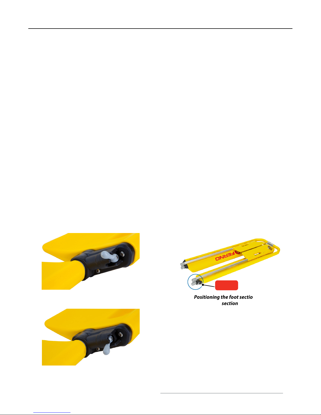
4.3 How to fold the stretcher
1. Place the stretcher on a at surface (the ground).
2. Place the locking levers in the unlocked position, facing upward, on both sides of the stretcher (Figure 8).
To unlock the latches, see Section 4.1 "Length adjustment", page 9.
3. Fully extend the foot section so that the hinges are fully exposed (Figure 9).
4. Place the foot section over the body section (Figure 9).
5. Place the levers in the locked position, facing downwards, on both sides of the stretcher (Figure 10).
6. If the stretcher is not used and is stored folded, ensure that all latches are in the closed position (facing downwards).
Figure 8 - Locking handles facing upwards Figure 9 - Positioning the foot section over the body
Figure 10 - Locking handle facing down
© Ferno Washington Italia ScoopExl - Rel.161115 - ENG
Hinges
section
11
Page 12
Stretcher conguration
SCOOP EXL Stretcher
4.4 How to extend the stretcher
In the event that the stretcher is folded (foot section over the body section, Figure 9), follow these steps to extend the stretcher:
1. Place the stretcher on a at surface.
2. Lift the foot section and place it on the same surface as the body section.
3. Release the locking levers so they are facing up (see section 4.1 "Length adjustment", page 9).
4. Adjust the length of the stretcher and lock it in the desired position (to correctly adjust the length of the stretcher see Section
4.1 "Length adjustment", page 9).
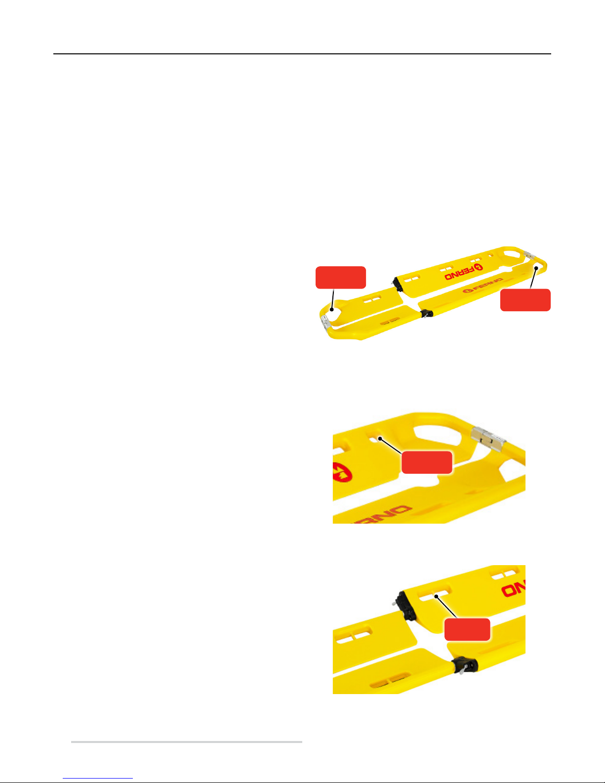
4.5 Lifting handles
The stretcher is equipped with four lifting handles at the
head end and the foot end.
Grasp the lifting handles to lift the stretcher (Figure 11).
Lift only the weight that you can safely support. Use
additional help when working with heavy loads (see Section
5.7 "Additional help", page 26).
Foot end
handles
Head-end
handles
4.6 Side holes
The stretcher is equipped with:
● 2 small lateral holes for fastening the "H"-shaped
Velcro band of the 365-E head immobilizer. The small
holes are provided only at the head end of the stretcher
(Figure 12).
● 8 side handles (4 per side). Each handle has a pin
inside for attaching restraint hooks (Figure 13).
4.7 Pin
The stretcher is equipped with 8 pins for attaching restraint
hooks. The pins are present in the side holes of the stretcher
(Figure 13).
Figure 11 - Lifting handles
Side holes
Figure 12 - Small side holes for "H"-shaped head
immobilizer
Pins
12
Figure 13 - Side holes with pin
© Ferno Washington Italia ScoopExl - Rel.161115 - ENG
Page 13

SCOOP EXL Stretcher
Using the Stretcher
5 USING THE STRETCHER
5.1 Before putting the
stretcher into service
Sta using the stretcher must have carefully read and
understood the information contained in this manual.
● Before any operation with the stretcher, ensure that all
components are present and that the stretcher shows
no sign of damage or wear, and is fully operational.
Refer to section 6.4 Inspection, page 28.
5.2 Instructions for Use
● This manual does not provide any medical instructions.
● It is the responsibility of the users to follow proper
procedures to ensure the safety of both the patient and
themselves.
● This manual explains the use of the stretcher in an
ideal situation and is purely indicative.
● The stretcher should be used only by trained and
qualied sta. A minimum of two trained and qualied
operators are required.
● Operators must work together and coordinate
properly during all operations.
● Follow the procedures applying standard protocols for
handling the patient in an emergency.
● Lift only the weight that you can safely support. Obtain
additional help when working with heavy loads.
● It is always required to follow the instructions and
local healthcare protocols.
● Always assist the patient and never leave the patient
alone during operations involving the stretcher.
WARNING
Improper use of the stretcher can cause damage
and / or injury. Use the SCOOP EXL stretcher as
described herein.
WARNING
Never leave the patient alone when bound to the
stretcher. Always assist the patient throughout all
rescue operations.
2
Read the user manual
carefully
227 kg
500 lb
36 st
Load capacity
At least two qualied
operators are required
WARNING
The use of improper and/or unauthorised devices
can cause accidents, damage and/or injury. Use only
devices that have been approved and authorised by
Ferno Washington Italia.
© Ferno Washington Italia ScoopExl - Rel.161115 - ENG
WARNING
Failure to use the restraints can cause the patient
to fall and endanger their safety. Always use the
containment restraints for the patient as indicated
herein.
WARNING
Never connect lifting devices directly to the
stretcher's pins. The pins are intended solely for
connecting the restraint hooks.
13
Page 14

Using the Stretcher
5.3 Applying the belts
Use restraints to secure the patient to the stretcher.
TWOPART RESTRAINTS WITH PLASTIC BUCKLES
1. Release the restraint by splitting it into two parts.
2. Passing one part of the restraint through the side
handle of the stretcher (Figure 14).
3. Thread the restraint buckle through the ring (Figure
14), then pull the restraint so that it wraps the
handle.
4. Repeat steps 1 through 3 for the other part of the
restraint.
5. Before any operation with the stretcher, check that
all the restraints are locked correctly and securely
and are in good condition.
TWOPART RESTRAINT WITH SNAP HOOK
Note: It is recommended that restraints with
hooks are used with SCOOP EXL stretchers fitted
with pins (section 4.7, Pins).
SCOOP EXL Stretcher
Figure 14 - Restraint with plastic buckle
6. Press the hook lever and attach the hook to the pin
(Figure 15).
7. Make sure the hook is attached and locked correctly
to the pin.
8. Repeat steps 1 through 3 for the other part of the
restraint.
9. Before any operation with the stretcher, check that
all the restraints are locked correctly and securely.
Important
Restraints tted with plastic buckles are ideal for use
within the hospital.
Restraints tted with snap hooks are suitable for
outside the hospital and for transport.
For the belts, see Section 7.3 Patient belts, page 31.
Figure 15 - Restraint with snap hook
14
© Ferno Washington Italia ScoopExl - Rel.161115 - ENG
Page 15

SCOOP EXL Stretcher
Using the Stretcher
5.4 Immobilization of the patient
The immobilization procedure should be performed by at least two trained and qualied operators. For the immobilization of
the patient, proceed as follows.
1. Align the patient (Figure 16).
2. Apply cervical collar if necessary (Figure 17). For the correct application of cervical collar consult the WizLoc collar
manual (to request copies of the manual contact Ferno Italia Customer Service, page 2).
Figure 16 - Aligning the patient Figure 17 - Fitting the cervical collar
3. Apply the immobilizer (Figure 18). For the correct application of the immobilizer refer to the 365-E head immobilizer
manual (to request copies of the manual contact Ferno Italia Customer Service, page 2).
4. Place the stretcher next to the patient, adjust the length of the stretcher so that it is suitable for the height of the patient
(Figure 19). To adjust the length of the stretcher, see section 4.1 Adjusting the stretcher, page 9.
Figure 18 - Fitting the head immobilizer Figure 19 - Adjusting the length of the stretcher
5. Before loading the patient on the stretcher, align the patient's jugular with small lateral holes on the stretcher (Figure 20).
Take additional care during this operation as this positions the patient correctly on the stretcher.
6. The two operators, arranged respectively at the foot and the head of the stretcher, open it by pressing the buttons on the
TSL system, longitudinally separating the two sides of the stretcher (Figure 21).
© Ferno Washington Italia ScoopExl - Rel.161115 - ENG
15
Page 16

Using the Stretcher
Figure 20 - Aligning the patient's jugular Figure 21 - Opening the stretcher
7. Position the two longitudinal parts under the patient, starting with the head end. If the patient is not cooperative, use a
third operator to hold the patient's head.
8. First close the head end via the TSL, ensuring the immobilizer is set correctly (Figure 22).
9. As the rst operator (head end) maintains control of the patient's head, the second operator proceeds to complete the
loading of the patient on the stretcher, and the locking of the foot end using the TSL (Figure 23 and 24).
SCOOP EXL Stretcher
Figure 22 - Closing the TSL (head end) Figure 23 - Closing the TSL (foot end)
Figure 24 - Completion of patient loading
16
WARNING
The operator at the head must check the patient's
alignment is correct, maintain contact with the
patient, and ensure they are on a smooth surface.
© Ferno Washington Italia ScoopExl - Rel.161115 - ENG
Page 17

SCOOP EXL Stretcher
10. Proceed with attaching the restraints. We recommend the use of 4 restraints:
• 2 thoracic restraints: 9 on 4 / 2 on 7
• 1 leg restraint: 7 on 4
• 1 foot restraint: 6 on 15
11. Apply the restraints as described below (Figure 25). For the application of the restraints and identication of the correct
holes on the stretcher, see Figure 25. In Figure 25 the numbering of the holes is clockwise from 1 to 10.
○ The two chest restraints should be applied in a cross conguration.
○ The leg restraints must be applied in transverse conguration.
○ The foot restraints must be applied in a gure-eight conguration.
Important
Do not separate the restraints
10
1
when attaching them, so as to
speed up the immobilization
process.
Using the Stretcher
LEFT SIDE
9
8
7
6 5
2
3
RIGHT
SIDE
4
WARNING
Always ll the popliteus hollow with spacers:
Figure 25 - Arrangement of patient immobilization restraints (operator view)
© Ferno Washington Italia ScoopExl - Rel.161115 - ENG
17
Page 18

Using the Stretcher
THORACIC RESTRAINTS
1. Attach the hook of the rst chest restraint to pin 9 (left side as viewed by the operator). Pass the restraint over the shoulder
and onto the patient's chest, then attach the second hook on the opposite side (right side relative to the operator) to pin 4
(Figure 25). Depending on the patient's size, you can proceed with attaching to pin 3 or 4.
2. Attach the hook of the second chest restraint to pin 2 (right side relative to the operator). Pass the restraint over the
shoulder and onto the patient's chest, then attach the second hook on the opposite side (right side relative to the operator)
to pin 4 (Figure 25). Depending on the patient's size, you can proceed with attaching to pin 7 or 8.
3. Adjust the tension of the restraints properly so as not to create unwanted stress to the patient.
SCOOP EXL Stretcher
Figure 26 - Applying the rst chest strap Figure 27 - Applying the second chest strap
Figure 28 - Adjusting the thoracic restraints
18
© Ferno Washington Italia ScoopExl - Rel.161115 - ENG
Page 19

SCOOP EXL Stretcher
BASIN RESTRAINT
1. Attach the rst hook to pin 7 (Figure 25).
2. Pass the restraint over the patient's legs.
3. Attach the hook to pin 4 on the opposite side.
4. Adjust the restraint correctly so as not to constrict the patient unnecessarily (Figure 30).
Using the Stretcher
Figure 29 - Applying the leg restraint Figure 30 - Adjusting the leg restraint
FOOT RESTRAINT
1. Attach the rst hook to pin 6 on the foot end.
2. Attach the second hook to pin 5 on the opposite side.
3. Extend the restraint (Figure 31) to allow creation of a gure-eight shape.
4. Cross the restraint and insert the foot into the loop (Figure 32).
5. Adjust the restraint so that the feet are held properly and securely (Figure 33).
Figure 31 - Extending the foot restraint Figure 32 - Inserting the feet through the loop
© Ferno Washington Italia ScoopExl - Rel.161115 - ENG
19
Page 20

Using the Stretcher
SCOOP EXL Stretcher
Important
If it is not possible to use the gure-eight restraint
conguration on the feet, or the patient has a splint
applied, proceed by attaching the restraint horizontally:
● Snap the rst hook to pin 6;
● Pass the restraint over the patient's feet;
● Snap the second hook to pin 5 on the opposite
side;
● Adjust the restraint so that the feet are correctly
and rmly locked.
Figure 33 - Foot restraint applied correctly
12. At the end of the process and after correct adjustment of restraints, pull together all the excess and arrange them so they
do not interfere with stretcher operations.
13. Once the application of the restraints is complete, proceed with the application of the H-shaped Velcro band to stabilize
and immobilize the patient's head. Apply the H-shaped Velcro band only after the restraints have been fully fastened.
14. Place the band over the patient's collar (Figure 34).
15. Insert the orange Velcro system into small side hole 10 (Figure 34; to identify hole 10, see Figure 25, page 17). Attach the
two constituent parts such that they cover the hole in the stretcher. Repeat the process on the opposite side.
16. Insert the black Velcro system into the lifting handle at the head end (Figure 35). Position it so that it is adjacent to the ear
hole of head immobilizer block. Attach the two parts that form the unit such that they wrap around the stretcher carrying
handle. Repeat the process on the opposite side.
17. Adjust the restraint to avoid placing excessive pressure on the neck.
Figure 34 - Applying the head strap Figure 35 - Applying the head strap
20
Ear hole
Block
© Ferno Washington Italia ScoopExl - Rel.161115 - ENG
Page 21

SCOOP EXL Stretcher
Using the Stretcher
18. Restraints with snap hooks are one of the patient
containment systems that can be used with the SCOOP
EXL stretcher. The E-770 "spider" system can be used
instead of the model 773 restraints (see Chapter 7
Accessories, page 31).
Figure 36 - Proper patient immobilization
Important
Apply the Velcro H-strap only AFTER setting the
restraints correctly.
Figure 37 - 770-E "spider" restraint system
© Ferno Washington Italia ScoopExl - Rel.161115 - ENG
21
Page 22

Using the Stretcher
SCOOP EXL Stretcher
WARNING
An unassisted patient is at risk of injury. Never leave
the patient alone when bound to the stretcher.
Always assist the patient during all operations with
the stretcher.
WARNING
Failure to use the restraints can cause the patient
to fall and endanger their safety. Always use the
containment restraints for the patient as indicated
herein.
Applications of the stretcher restraints that are not
as described in this manual could cause accidents,
damage and / or injury.
The tilting procedure requires specic skills and
MUST NOT be performed by operators who have not
received professional instruction and training.
WARNING
WARNING
5.5 Tilting the patient
The tilting procedure should be performed by at least two trained and qualied operators. It should not be performed by
operators who have not received professional "LIMITED SPACE MANOEUVRES" instruction and training. For training
courses, contact Ferno Washington Italia's Customer Services (page 2).
To tilt the patient, proceed as follows:
1. Align the patient (Figure 16).
2. Apply cervical collar if necessary (Figure 17). For the correct application of cervical collar consult the WizLoc collar
manual (to request copies of the manual contact Ferno Italia Customer Service, page 2).
3. Apply the immobilizer (Figure 18). For the correct application of the immobilizer refer to the 365-E head immobilizer
manual (to request copies of the manual contact Ferno Italia Customer Service, page 2).
4. Place the stretcher next to the patient, adjust the length of the stretcher so that it is suitable for the height of the patient
(Figure 19). To adjust the length of the stretcher, see section 4.1 Adjusting the stretcher, page 9.
5. Before loading the patient on the stretcher, align the patient's jugular with small lateral holes on the stretcher (Figure 20).
Take additional care during this operation as this positions the patient correctly on the stretcher.
6. The two operators, arranged respectively at the foot and the head of the stretcher, open it by pressing the buttons on the
TSL system, longitudinally separating the two sides of the stretcher (Figure 21).
7. Position the two longitudinal parts under the patient, starting with the head end. If the patient is not cooperative, use a third
operator to hold the patient's head.
8. First close the head end via the TSL, ensuring the immobilizer is set correctly (Figure 22).
9. As the rst operator (head end) maintains control of the patient's head, the second operator proceeds to complete the
loading of the patient on the stretcher, and the locking of the foot end using the TSL (Figure 23 and 24).
10. Proceed with attaching the restraints. We recommend the use of 4 restraints:
• 1 x thoracic restraint: 9 on 2
• 2 x inguinal restraints: 8 on 8 / 3 on 3
• 1 x foot restraint: 6 on 5
11. Apply the restraints as described below (Figure 38). For the restraint conguration and identication of the correct holes
on the stretcher, refer to Figure 38. In Figure 38 the numbering of the holes is clockwise from 1 to 10.
22
© Ferno Washington Italia ScoopExl - Rel.161115 - ENG
Page 23

SCOOP EXL Stretcher
Using the Stretcher
Important
To improve patient comfort,
insert padding on pressure
points.
LEFT SIDE
10
9
8
7
6 5
1
2
3
RIGHT
SIDE
4
Figure 38 - Arrangement of restraints for patient tilting
(operator view)
WARNING
The tilting procedure requires specic skills and
MUST NOT be performed by operators who have
not received professional instruction and training.
© Ferno Washington Italia ScoopExl - Rel.161115 - ENG
Important
When tilting the patient, make sure not to exceed an
angle of 70°, and maintain the inclined position for
the minimum possible period.
23
Page 24

Using the Stretcher
THORACIC RESTRAINT
1. Snap the rst hook to pin 2 (right side as viewed by the operator, Figure 38).
2. Pull the restraint under the armpit of the patient; in the case of a female patient the restraint must pass over breast.
3. Snap the second hook to pin 9 on the opposite side (left side as viewed by operator).
4. Adjust the tension of the belts properly so as not to create unwanted stress to the patient.
INGUINAL RESTRAINTS
1. Insert the long end of the rst restraint between the patient's legs, a little above the crest.
2. Pull the restraint under the right leg and snap both hooks to pin 3 (right side as viewed by operator) making sure that the
restraint wraps the leg in the groin area.
3. Do the same on the other side with the left leg and attach both restraint hooks to pin 8 (left side as viewed by operator).
4. Adjust the tension of the restraints properly so as not to create unwanted stress to the patient.
FOOT RESTRAINT
1. Attach the rst snap hook to pin 6 on the foot end.
2. Attach the second snap hook to pin 5 on the opposite side.
3. Extend the restraint (Figure 31) to allow creation of a gure-eight shape.
4. Cross the restraint and insert the foot through the loop (Figure 32).
5. Adjust the restraint so that the feet are held properly and securely (Figure 33).
12. At the end of the process and after correct adjustment of restraints, pull together all the excess and arrange them so they
do not interfere with stretcher operations.
13. Once the application of the restraints is complete, proceed with the application of the H-shaped Velcro band to stabilize
and immobilize the patient's head. Apply the H-shaped Velcro band only after the restraints have been fully fastened.
14. The application of H-shaped Velcro strap is described on page 20.
SCOOP EXL Stretcher
CAUTION: Pad the restraints' pressure points to improve patient comfort.
WARNING
Failure to use the restraints correctly may cause the
patient to fall and endanger their safety. Always
use the containment restraints for the patient as
indicated herein.
Important
Apply the Velcro H-strap only AFTER setting the belts
correctly.
24
If it is not possible to use the gure-eight restraint
conguration on the feet, or the patient has a splint
applied, proceed by attaching the restraint horizontally:
● Snap the rst hook to pin 6;
● Pass the restraint over the patient's feet;
● Snap the second hook to pin 5 on the opposite
● Adjust the restraint so that the feet are correctly
Important
side;
and rmly locked.
© Ferno Washington Italia ScoopExl - Rel.161115 - ENG
Page 25

SCOOP EXL Stretcher
Using the Stretcher
5.6 Lifting and carrying
Before transporting, make sure that:
1) the patient's cervical collar, the head immobilizer and seat restraints have been applied,
2) the patient is correctly secured on the stretcher,
3) TSL systems are properly connected and locked (to lock the stretcher properly, see section 4.2 Twin Safety Lock (TSL)
System, page 10)
4) the latching side levers are in the locked position facing down (to lock the stretcher, see Section 4.1 Adjusting the length,
page 9).
To immobilize the patient on the stretcher properly, see section 5.4 Patient immobilization, page 15.
Carry the stretcher carefully on uneven surfaces. Two trained and qualied operators are required for lifting and transportation
of the stretcher.
If transporting a heavy adult patient, lift and carry the stretcher with the use of additional help (paragraph 5.7 Additional help,
page 26).
To carry the stretcher, proceed as follows:
1. Position operators at each end (head end and foot end) of the stretcher. If additional helpers are involved, use positions as
indicated in paragraph 5.7 Additional help, page 26.
2. Grasp the lifting handles with your palms facing up.
3. Both operators: coordinating with each other, proceed with lifting and carrying of the stretcher and patient. Use suitable
techniques for lifting and carrying the stretcher.
Only lift weight that each person can manage safely. Use additional trained operators when lifting and carrying the stretcher.
Refer to Section 5.7 Additional help, page 26.
Proceed as follows for carrying the stretcher in a vehicle:
WARNING: Reset restraints set for tilting the patient to standard immobilization conguration before moving the vehicle.
WARNING
Improper use of the stretcher can cause damage
and / or injury. Use the SCOOP EXL stretcher as
described herein.
WARNING
Untrained users may injure themselves and/or
cause damage and/or physical harm. Allow only
trained and qualied sta to use the SCOOP EXL
stretcher.
Never exceed the load capacity of the stretcher as
specied in this manual.
Never connect lifting devices directly to the
stretcher's pins. The pins are intended solely for
connecting the restraint hooks.
WARNING
WARNING
© Ferno Washington Italia ScoopExl - Rel.161115 - ENG
25
Page 26

Using the Stretcher
SCOOP EXL Stretcher
5.7 Additional Help
Two trained and qualied operators are required for the use of the stretcher. Operators may need assistance to lift heavy adult
patients.
● The trained operators must stand at the head and foot end of the stretcher, they must always maintain control of the
stretcher and direct their assistants.
The illustrations below show the positioning of operators and helpers. It is very important that the operators are always opposite
each other to maintain eye contact.
WARNINGS
Casual assistants may cause damage and/or
physical harm, or injure themselves. Do not allow
casual helpers to perform stretcher preparation
operations. Be extremely careful during all user
operations.
26
Load capacity
Never exceed the load capacity of
227 kg
500 lb
36 st
SWR- Strength to Weight Ratio = 28.4
Safety factor = 2
© Ferno Washington Italia ScoopExl - Rel.161115 - ENG
the SCOOP EXL stretcher. Inspect
the stretcher if the carrying capacity
has been exceeded (see section 6.4
Inspection, page 28).
Page 27

SCOOP EXL Stretcher
Maintenance
6 MAINTENANCE
6.1 Routine maintenance
The stretcher requires regular routine maintenance. It is
recommended to perform preventive maintenance on the
stretcher each year. When the device is put to particularly
heavy use, maintenance should preferably be carried out
on a more frequent basis by Ferno's technical personnel.
Repairs must be performed by Ferno's qualied personnel
using original spare parts.
If you discover signs of wear and damage, place the stretcher
out of use and immediately contact Ferno's Technical
Assistance Service (page 2).
6.2 Disinfection
1. After each use, clean the surfaces of the stretcher with a
cloth and a non-abrasive surface disinfectant.
2. It is advisable to extend the leg section to the furthest
position and disinfect with the stretcher in an upright
position (foot end down).
3. Do not immerse the stretcher directly in disinfectant.
4. During disinfection, check that there are no signs of
wear and/or damage.
5. Dry with a cloth. Make sure that all the components of
the device are completely dry before reusing them.
It is advisable to wear suitable gloves (e.g. household or
disposable gloves) during disinfection.
6.3 Cleaning
1. Clean all surfaces of the stretcher with a cloth, warm
water and soap or a mild detergent soap.
2. If necessary, to remove stains, use a soft brush or a light
solvent, paying attention to labels.
3. Dry with a cloth. Make sure that all the components of
the device are completely dry before reusing them.
Do not wash with high pressure water
It is advisable to wear suitable gloves (e.g. household or
disposable gloves) during disinfection.
Important
The use of products containing bleaches, phenols and
iodine can damage the stretcher. Do not use products
containing these elements for cleaning and disinfecting
the stretcher.
Maintenance Periods
Disinfection (page 27)
Cleaning (page 27)
Inspection (page 28)
Lubrication (page 29)
© Ferno Washington Italia ScoopExl - Rel.161115 - ENG
After each use
Whenever
necessary
• •
• •
• • •
•
Monthly
Important
After disinfection/cleaning, ensure the stretcher and its
components are fully and completely dry before use.
Important
DO NOT WASH WITH HIGH PRESSURE WATER
Do not use high-pressure water to clean
the stretcher.
27
Page 28

Maintenance
6.4 Inspection
SCOOP EXL Stretcher
To ensure optimal use of the stretcher, it is important to
keep all the components in good condition and to remove all
traces of dirt, debris and bodily uids.
The stretcher must be inspected before and after each use,
and cleaned after each use. While not in use, it must be
stored in a dry indoor environment and should be inspected
at least once a month.
Ensure the stretcher is regularly inspected by trained
maintenance personnel. Perform the checks listed on this
page.
If any signs of wear or damage are found during inspection,
discontinue use of the stretcher immediately and contact
Ferno's Technical Support Service to request repair or
maintenance.
Refer to Chapter 8 Technical Assistance, page 31.
CHECKLIST FOR
STRETCHER INSPECTION
● Does the stretcher show signs of damage or wear?
Are all the components present?
● Are the two chest belts, the leg belt, and the feet belt
present?
● Are the straps in good condition, without tears or
frayed edges?
● Do the snap hooks and belt buckles attach rmly,
and not show any visible damage?
● Do the moving parts (couplings, levers, hooks and
telescopic sections) work properly?
● Is the Twin Safety Lock system working properly?
Does the stretcher close and lock correctly, uniting
the two halves of the stretcher securely?
● Are the latching levers functioning properly?
● Is it possible to lengthen the stretcher and lock it
properly in the 4 positions?
● Are the attachment pins xed in their seats? Refer
to section 6.6 Inspection and locking of the coupling
pins, page 29).
● Are the pins for the belt snap hooks xed in their
seats?
● Do the attachments for the head and feet require
lubrication?
● Are there visible signs of damage on the stretcher or
its components?
Important
Store the SCOOP stretcher EXL in an indoor
environment, dry and protected from direct sunlight.
28
WARNING
Improper maintenance can cause serious accidents,
injuries and/or damage. Perform maintenance as
instructed in this user manual.
© Ferno Washington Italia ScoopExl - Rel.161115 - ENG
Page 29

SCOOP EXL Stretcher
6.5 Lubrication
Maintenance
Clean and disinfect the stretcher before lubricating it. Use
appropriate lubricants.
The couplings for the head and foot sections are lubricated
during assembly of the stretcher, but may require additional
lubrication, if necessary, during normal use.
It is possible to use one of the following methods (A or B)
of lubrication:
A. WHITE LITHIUM GREASE: apply a small amount of
white lithium grease on the sliding surfaces of the couplings.
Remove any excess.
B. GENERAL TEFLON LUBRICANT SPRAY: spray
a small amount of lubricant on sliding surfaces of the
couplings. Remove any excess.
Important
If you lubricate components that do not need to be
lubricated, this may allow dirt and foreign particles to
accumulate, causing damage to these components.
Lubricate only the components indicated.
During assembly of the stretcher, thread-lockers are applied
corresponding with such pins. If a pin has come loose, it is
possible to apply an additional thread-locker, as reported in
the subsection "Reinstalling the pins".
The procedures described should be solely and exclusively
by qualied technical sta. Contact Ferno Washington
Italia's Technical Support Service (page 2).
INSPECTION OF THE PINS
To check if the pin is loose, proceed as follows:
1. Use 12 mm max. needle-nose pliers
2. Cover the nose pliers with duct tape to prevent damage
to the surface of the pins.
3. Try to unscrew the rst pin. If the pin holds and
you cannot unscrew it without further eort, the pin
is locked into place. If the pin is unscrewed easily,
follow the instructions in the subsection "Reinstalling
the pins".
4. Check the remaining three pins and reinstall only the
pins that are not locked properly.
6.6 Inspection and locking of the
coupling pins
Each Twin Safety Lock (TSL) system includes two threaded
pins (Figure 39).
Pin
Figure 39 - Pin
RE-INSTALLATION OF THE PINS
In the event that one of the pins is loose, proceed as follows
to lock it properly:
1. Unscrew the loose pin and remove it from the Twin
Safety Lock system.
2. Completely remove all traces of thread-locker in the
pin's thread and seat.
3. Dry the cleaned surfaces of the thread of the pin and
seat.
4. Apply Loctite 270 on the dried surfaces of the two
threads until they are completely covered by the thread
locker.
5. Insert the pin into the coupling seat and use the pliers
to tighten it.
6. Remove any excess thread-locker.
7. Let the thread-locker dry for a few hours before
resuming use of the stretcher.
If a pin is missing, put the stretcher out of service immediately
and contact Ferno Washington Italia's Technical Assistance
Service (page 2).
© Ferno Washington Italia ScoopExl - Rel.161115 - ENG
29
Page 30

Maintenance
SCOOP EXL Stretcher
6.7 Storage
The stretcher must be stored in a clean, dry, indoor place,
away from direct sunlight. When not in use, it can be stored
in its practical carrying bag (Figure 40).
The stretcher must be folded up to t inside the carrying
bag (Figure 9, page 11). To fold the stretcher properly, see
Section 4.3 How to fold the stretcher, page 11.
Figure 40 - Emergency Kit Storage Bag
ACCESSORIES AND RELATED PRODUCTS
Ferno oers a full range of accessories for emergency medical services. Follow the instructions provided with the product.
Keep the instructions together with this manual. When you are using accessories, pay attention to additional factors such as
height and width of doors, etc. For more information, contact the Ferno Customer Support.
30
TSL Extender
Saerbag 3 (hoistable rescue bag)
SS-Shoulder Support
(transport harness)
WARNING
The use of incorrect or unsuitable items on the
stretcher may cause injury. Use only approved items
from Ferno on the stretcher.
© Ferno Washington Italia ScoopExl - Rel.161115 - ENG
Page 31

SCOOP EXL Stretcher
7 ACCESSORIES
Ferno oers various accessories approved for use with the
SCOOP EXL stretcher. Always follow the directions in this
instruction manual. For more product information, contact
Ferno Customer Service (page 2).
7.1 SCOOP EXL stretcher accessories
Description Code
Head Immobilizer 365-E
WizLoc 449-I Cervical Collar (3 pcs.) 0822074
WizLoc Cervical Collar, for military (1 pc.) 0819759
Emergency Bag / backpack FBI300000
EasyLift, long hangers PS0765EXL
EasyLift, short hangers PS0765EXL/S
Horizontal restraint 561-O
Vertical restraint 561-V
365-E transport / storage bag 10-9900-005
TSL Extender
SS-Shoulder Support 21-0120-11
Emergency Kit - Transport Bag
7.2 SCOOP EXL Stretcher Models
Description Code
SCOOP EXL stretcher, yellow with 4 restraints,
mod.773 (metal buckle and hook) for use
outside hospital
SCOOP EXL stretcher, yellow with 3 x 2-part
restraints (plastic buckle and hook) for inhospital use
SCOOP EXL Kit complete with 1 x SCOOP EXL,
yellow with pin, 1 x 365-E head immobilizer,
with carrying / storage bag and 4 x 773 restraints
EMERGENCY KIT complete with 1 x yellow
SCOOP EXL, with pin, 1 x 365E head immobilizer,
1 x WIZLOC collar, 4 x restraints (mod.773),
FW100 blanket, bag/backpack
TSL Extender
Emergency
Kit
0108004IT/773
0108004PIT
KIT-65EXL/773
65EXL-EK
Accessories / Technical Assistance
7.3 Patient belts
Description Code
773 Restraints, 2-piece with buckle and metal hook 0314009
"Spider" restraint system 770-E
436 restraints, 2-piece with metal buckle and snap
hook (3 pcs.)
2-piece restraints with plastic buckle, black / red
logo
2-piece restraint with plastic buckle and hook 0313847
2-piece restraint with metal buckle, burgundy 430-2-201
1-piece restraint with metal buckle, red logo 430-1-N
1-piece restraint with plastic buckle, burgundy 430-PA-1-201
2-piece restraint with metal buckle, burgundy 430-PA-2-201
2-piece restraints with plastic buckle, black with red
logo
1-piece restraint with plastic buckle, black/red logo 430-PA-1-N
0313079
430-PA-2-N
430-2-N
WARNING
The use of improper and/or unauthorised devices
can cause accidents, damage and/or injury. Use only
devices that have been approved and authorised by
Ferno Washington Italia.
© Ferno Washington Italia ScoopExl - Rel.161115 - ENG
31
Page 32

Warranty
SCOOP EXL Stretcher
9 WARRANTY
9.1 Warranty Terms & Conditions
Ferno's products are guaranteed against manufacturing
defects for a period of 24 months from the date on the Ferno
Washington Italia s.r.l. shipping document.
Ferno Washington Italia guarantees its replacement parts for
a period of 12 months.
During the warranty period, Ferno will repair and/or replace
any parts found to have manufacturing defects, excluding
the costs of: manual labour, travel, transport, and packaging.
The warranty does not cover consumables or parts prone
to wear and tear due to normal use of the product, all parts
typically subjected to sliding or rolling friction (bearings,
brushes, lubricants, shoes, tracks, etc.), parts potentially
exposed to oxidation or corrosion (copper or metal alloy
contacts, mechanical equipment), or batteries.
The surface nishes (gelcoat/resin, paint, powder paint,
decals, tape, printing, etc.) are guaranteed for 90 days.
Repairs are performed by trained technical sta at the
Washington Ferno Italia s.r.l. site in Via Zallone 26- 40066
Pieve di Cento (BO), or at the Customer's premises if
suitable arrangements with Ferno Washington Italia's
Customer Services have been made.
Technical support at the Customer's premises must be
arranged beforehand and involves a refund of costs incurred
and documented on request. For information on the costs of
technical support, please contact the relevant oce at Ferno
Washington Italia s.r.l..
Repairs are guaranteed for 6 months from the date of
repair. This warranty applies only when the product is used
according to the instructions in the user manual provided.
Misuse and negligence invalidates this warranty.
The warranty is valid from the day the product is shipped
from Ferno Washington Italia s.r.l., and the shipping rates
are not covered by this warranty. Ferno Washington Italia
s.r.l. is not liable for damages sustained during shipment or
due to misuse of the product.
Products sold by Ferno Washington Italia s.r.l. that do not
bear the Ferno trademark are covered by the warranty of the
original manufacturer. Ferno Washington Italia s.r.l. does
not extend the periods of warranties of other manufacturers;
Ferno Washington Italia s.r.l. assumes no responsibility for
products manufactured by others.
The warranty is rendered null and void in the case of:
- Failure to observe the instructions on use,
- Misuse,
- Inappropriate use or handling,
- Repairs by non-authorised persons,
- Damage during transport due to improper packaging of
items returned by the user,
- Inadequate maintenance,
- Failure to use original spare parts.
In cases not covered by the warranty, Ferno Washington
Italia does not bear the transport costs for sending or
returning the product.
9.2 Limitation of liability
If a product is found to be defective, Ferno Washington
Italia s.r.l. will repair and replace it, or, at its own discretion,
refund the purchase price. Under no circumstances can
Ferno Washington Italia s.r.l. be held liable for more than
the sale price of the product. The buyer accepts these
conditions for all types of damage. Ferno Washington
Italia s.r.l. does not oer other warranties, either express or
implied, or any implied warranties of merchantability and
tness for a particular purpose for its own products, or those
manufactured
by others. In case of infringement of the limited warranty,
any legal actions must be led within one year from the
date on which the infringement was, or should have been,
discovered. Ferno Washington Italia s.r.l. reserves the right
to terminate the warranty of the products sold:
- If the labels or plates bearing the manufacturer's logo and/
or the serial or registration number are rendered illegible or
removed;
- If the product has undergone modications, repairs or
treatment unauthorized by Ferno Washington Italia, and/or
by personnel not authorized by Ferno Washington Italia;
- If the product is not used in compliance with the
instructions, or for purposes other than those for which it
was designed.
- as indicated in section 9.1, "Warranty Terms & Conditions".
Ferno Washington Italia s.r.l. cannot, in any event, be held
liable for direct or indirect damage due to usage that is noncompliant with the instructions in the user manual or the
intended purpose of the product.
32
© Ferno Washington Italia ScoopExl - Rel.161115 - ENG
Page 33

SCOOP EXL Stretcher
Warranty
9.3 Warranty claims
Contact Ferno's Customer Service immediately if you receive
a product that is suspected to be defective. A representative
will assist the customer through the complaints procedure.
Before returning a product to Ferno Washington Italia s.r.l.,
contact Ferno's Customer Service to request authorisation.
9.4 Complaints
Any complaints must be communicated to the reseller, or to
Ferno Washington Italia s.r.l.'s Customer Service, within 5
days of receipt of the product or of discovery of the alleged
defect.
Claims or disputes regarding a single product does not
release the buyer from the obligation to collect and pay for
other products in the order, unless otherwise agreed with the
seller.
9.5 Return authorization
No product will be accepted without the prior approval of
Ferno Washington Italia s.r.l..
Products returned for business reasons, or for reasons
not relating to lack of conformity of the product, will be
accepted only after verication of their condition by Ferno
Washington Italia s.r.l. qualied personnel.
8.1 Technical Support Service
For technical support concerning our products, please
contact Ferno Washington Italia's Technical Support Service.
Telephone (toll-free, Italy only) 800 501 711
Phone +39 05 16860028
Fax +39 05 16861508
Email info@ferno.it
Internet www.ferno.it
For information on using the SCOOP EXL stretcher, and to
schedule training courses on the correct use of the device,
contact Ferno Washington Italia's Customer Service team.
© Ferno Washington Italia ScoopExl - Rel.161115 - ENG
8 TECHNICAL SUPPORT
WARNING
Non-original spare parts and inadequate repairs
may cause damage and/or injury. Use only Ferno
original parts and contact only Ferno Washington
Italia's Customer Support.
WARNING
Unauthorized modications to the SCOOP EXL
stretcher can cause serious damage, injury and / or
unpredictable problems. Do not modify or alter the
stretcher in any way.
33
Page 34

SCOOP EXL Stretcher
BIBLIOGRAPHY
Krell et. al, Comparison of the Ferno Scoop Stretcher with the long backboard for spinal immobilization, Prehospital
Emergency Care, 2006; 10: 46-51.
Advanced Trauma life support course for physicians, American college of surgeons, 9th edition, 2012.
Prehospital Trauma life support, the national Association of emergency medical technicians in cooperation with the
committee on trauma of the American college of surgeons, 7th edition, 2011.
Boissy et al., Eectiveness of cervical spine stabilization techniques, Clinical journal of sport medicine, 2011; 21: 80-88.
Ben-Galim et al., Extrication collars can result in abnormal separation between vertebrae in the presence of a dissociative
injury, The journal of Trauma, 2010; 69: 447-50.
Conrad et al., Eliminating log rolling as a spine trauma order; Surgical neurology International; 2012; 3 - supp 3: S188-197.
Domeier et al., Prospective performance assessment of an out of hospital protocol for selective spine immobilization using
clinical spine clearance criteria, Annals of Emergency Medicine, 2005; 46: 123-31.
Bombardier et al., Symptoms of major depression in people with spinal cord injury: implication for screening, Archives of
Physical Medicine and rehabilitation, 2004; 85: 1749-1756.
Jackson et al., A demographic prole of a new traumatic spinal cord injuries: change and stability over 30 years, Archives of
Physical Medicine and rehabilitation, 2004; 85:1740-1748.
Connell et al., Is spinal immobilization necessary for all patients sustaining penetrating trauma?, Injury, 2003: 34: 912-914.
Domeier et al., Multicenter prospective validation of prehospital clinical spinal clearance criteria, The journal of trauma,
2002; 53: 744-750.
Stroh et al., Can an out of hospital cervical spine clearance protocol identify all patients with injuries? An argument for
selective immobilization, Annals of emergency medicine, 2001; 37: 609-615.
Domeier et al. Prospective validation of out of hospital spinal clearance criteria: a preliminary report, Academic emergency
medicine, 1997; 4: 643-646.
DeVivo et al., Causes and costs of spinal cord injury in the United States, Spinal Cordo, 1997; 35: 809-813.
34
© Ferno Washington Italia ScoopExl - Rel.161115 - ENG
Page 35

SCOOP EXL Stretcher
TRAINING RECORD
Date Instructor Name Training Type
© Ferno Washington Italia ScoopExl - Rel.161115 - ENG
35
Page 36

SCOOP EXL Stretcher
MAINTENANCE RECORD
Date Type of Maintenance Maintenance Technician
36
© Ferno Washington Italia ScoopExl - Rel.161115 - ENG
Page 37

SCOOP EXL Stretcher
User and maintenance manual of the product, required for safe operation, maintaining the eciency and reliability of the
product, and ensuring the validity of the warranty.
Rel.161115
English (UK)
Ferno Washington Italia s.r.l.
Via Benedetto Zallone, 26
40066 - Pieve di Cento (BO) - ITALY
Telephone (toll-free in Italy) 800 501 711
Phone +39 0516860028
Fax +39 0516861508
E-mail info@ferno.it
Internet www.ferno.it
© Ferno Washington Italia ScoopExl - Rel.161115 - ENG
37
 Loading...