

Page 1
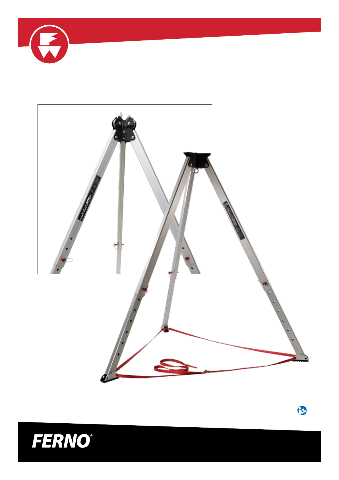
IndustriPOD® / IndustriPOD+®
Tripod Series
IndustriPOD+®
IndustriPOD®
Read this Manual and Retain
for Future Reference
© Ferno Australia / 00425-V1 / Aug 2018
Users’ Manual
Doc ID: 00425-V1 / July 2018
1
Page 2
Ferno Customer Service
For ordering, product assistance or general information:
AUSTRALIA
Telephone (Toll-free) 1800 804 647
Telephone (07) 3881 4999
Fax (07) 3881 1125
Email [email protected]
Internet www.ferno.com.au
ALL OTHER LOCATIONS
For assistance or information, please contact your Ferno distributor. If
you do not have a Ferno distributor, please contact Ferno Customer
Service:
Ferno Australia, 11 Johnstone Road,
Brendale, Queensland 4500, Australia
USERS’ MANUALS
To request additional free users’ manuals,
contact Ferno Customer Relations, your Ferno
distributor, or www.ferno.com.au
Device Serial Number:
Disclaimer
This manual contains general instructions for the use, operation
and care of this product. The instructions are not all-inclusive. Safe
and proper use of this product is solely at the discretion of the user.
Safety information is included as a service to the user. All other safety
measures taken by the user should be within and under consideration
of applicable regulations and local protocol. Training on the proper
use of this product must be provided before using this product in an
actual situation.
Retain this manual for future reference. Include it with the product in
the event of transfer to new users. Additional free copies are available
upon request from Customer Service.
Proprietary Notice
The information disclosed in this manual is the property of Ferno
Australia (herein referred to as Ferno). Ferno reserves all intellectual
property rights, proprietary design rights, manufacturing rights,
reproduction use rights, and sales use rights thereto, and to any article
disclosed therein except to the extent those rights are expressly
granted to others or where not applicable to vendor proprietary
parts.
Limited Warranty Statement
Ferno products are warranted to be free from defects in material and
workmanship for a period of one year, except as follows:
• External nishes (gelcoat, paint, powdercoat, decals, etc.) are
warranted for 90 days.
• Soft goods (webbing, vinyl, fabric, foam, etc.) are warranted for
90 days.
Ferno repairs are warranted for 90 days from the date of repair.
This limited warranty applies only when you use and care for the
product as described in the instructions provided with the product.
Improper use and care may void this warranty. The warranty period
begins the day the product is shipped from Ferno or the day you
receive it if you have proof of the delivery date. Shipping charges are
not covered by this limited warranty. Ferno is not liable for shipping
damages or damages sustained through using the product, nor does
Ferno assume any liability for products manufactured by others.
Limitation of Liability
If a product is proven defective, Ferno will repair or replace it, or, at
our option, refund the item’s purchase price. In no event is Ferno
liable for more than the selling price of the product. The purchaser
accepts these terms in lieu of all damages.
Except for the limited warranty above, Ferno makes no other
warranties, either expressed or implied. Ferno makes no implied
warranties of merchantability and tness for a particular purpose for
its own product or for the products of others. In no event will Ferno
be liable for any indirect or consequential damages sustained in
connection with the delivery, use, or performance of its products.
44 (0) 1274 851999
2
© Ferno Australia / 00425-V1 / Aug 2018
Page 3

TABLE OF CONTENTS
Ferno Customer Service __________________________________ 2
1 SAFETY INFORMATION _________________________________ 4
1.1 Warning __________________________________________ 4
1.2 Notice ___________________________________________ 4
1.3 Glossary __________________________________________ 4
1.4 Product Lifespan Statement __________________________ 4
2 ABOUT THE PRODUCT __________________________________ 5
2.1 Description _______________________________________ 5
2.2 Specications _____________________________________ 6
2.3 Compatible Components ____________________________ 6
3 INSTRUCTIONS FOR USE ________________________________ 7
3.1 General Safety Instructions __________________________ 7
3.2 Before Each Use ___________________________________ 7
3.3 IndustriPOD® Assembly _____________________________ 8
3.4 Setting up the IndustriPOD® _________________________ 9
3.5 IndustriPOD® as a high anchor _______________________ 10
3.6 IndustriPOD® as a change of direction ________________ 11
3.7 Stabilisation rigging for the head ___________________ 12
3.8 Two points of contact ____________________________ 13
4 INSPECTIONS ________________________________________ 14
4.1 Operator Inspection _______________________________ 14
4.2 Periodic Inspections _______________________________ 14
5 MAINTENANCE, STORAGE & TRANSPORT ________________ 15
5.1 Cleaning IndustriPOD® _____________________________ 15
5.2 Storing IndustriPOD® ______________________________ 15
5.3 Transporting IndustriPOD® __________________________ 15
6 SERVICING & PARTS ___________________________________ 15
6.1 Servicing IndustriPOD® _____________________________ 15
6.2 Spare Parts ______________________________________ 15
7 ACCESSORIES ________________________________________ 16
7.1 Optional Accessories ______________________________ 16
8 INSPECTION & MAINTENANCE RECORDS ________________ 17
© Ferno Australia / 00425-V1 / Aug 2018
3
Page 4
SAFETY INFORMATION
1 SAFETY INFORMATION
NOTICE
EMPLOYER: It is your responsibility to ensure all users are instructed and trained in the correct use and maintenance of the equipment. Once
equipment is issued, it is assumed this has been completed.
USER: Only competent users should use this equipment. It is your responsibility to read and understand these instructions and be properly
trained in the use of this equipment. Always use equipment safely and properly. Check equipment before and after each use
GENERAL: This document is not intended as a substitute for appropriate training. Training, practice and experience in technical rigging are
essential for safe use. Modifying the equipment can cause injury and damage and will nullify any warranty and place full responsibility for any
accident or injury on the equipment owner.
Working at heights and in conned spaces can be dangerous. If you use Ferno equipment, you are responsible for learning and
observing safe techniques. Ferno Australia disclaims all liability for any injury or loss arising from the use of this equipment when
any of its components are damaged or weakened by wear and tear.
1.1 Warning
Warning safety alerts indicate a potentially hazardous situation that,
if not avoided, could result in injury or death.
WARNING
Do not use the IndustriPOD® beyond the specied
limitations, or for any purpose other than that for which
it is intended.
Ensure the compatibility of equipment used within the
system. Dangers may arise when the safe function of any
one item of equipment is aected by or interferes with
the safe function of another.
1.2 Notice
Notices emphasize important, but not hazard-related information.
Failure to follow Notices could result in product or property damage.
NOTICE
1.3 Glossary
Throughout this Manual, the IndustriPOD® and IndustriPOD+® will
be referred to as IndustriPOD®. Where instructions are specific to a
model, that tripod model will be specified.
1.4 Product Lifespan Statement
The actual life span of the Industripod cannot be predicted exactly, as
it is inuenced by many factors including but not limited to frequency
and intensity of use, environment, weather, storage conditions, etc.
For metallic products it is advisable to replace after 10 years, however
the life span is theoretically indenite, with strict adherence to
the maintenance and inspection guidelines contained within this
booklet.
If there is any doubt about the safety of a product, do not use and
contact your safety representative or the manufacturer.
It is always recommended to review the manufacturer’s instructions
as a life span may be restricted due to application or applicable
product standards.
4
© Ferno Australia / 00425-V1 / Aug 2018
Page 5

ABOUT THE PRODUCT
2 ABOUT THE PRODUCT
2.1 Description
The IndustriPOD® tripod series are heavy-duty, versatile and durable
tripods that exceed the criteria of most international standards.
Both IndustriPOD® models have built-in safety factors equivalent to
internationally recognised rescue systems.
Their design and simplicity of use make them ideal for any heavyduty conned space requirement where guaranteed performance is
mandatory.
OPTIONAL ACCESSORIES
● Available accessories are listed on Page 16 of this user manual.
w
q
e
r
PARTS IDENTIFIER
REF INDUSTRIPOD® QUANTITY
IndustriPOD® Head
q
Stabilisation Point
w
Side Plate Anchor Point
e
M12 S/S Eyebolt Anchor Point
r
Leg Pin
t
Adjustable Foot Tether
y
Tripod Feet 3
u
REF INDUSTRIPOD+® QUANTITY
IndustriPOD+® Pulley Head
q
Stabilisation Point
w
Side Plate Anchor Point
e
Head Pulley
r
Pulley Detent Pins
t
Adjustable Foot Tether
y
Tripod Feet 1
u
Leg Pin 3
i
1
3
3
1
3
1
1
3
3
2
2
1
u
t
q
y
r
IndustriPOD®
t
w
e
© Ferno Australia / 00425-V1 / Aug 2018
Bracket accessory shown,
but not included
Foot Tether (not shown)
y
i
u
IndustriPOD+®
5
Page 6

ABOUT THE PRODUCT
INDUSTRIPOD® FEATURES
● Rectangular, adjustable legs with quick-action ball lock leg pins
● One-piece fabricated steel head
● One stainless steel M12 swivel eyebolt anchor point
● Three side plate anchor points
● Three tie-o points for rigging or stabilisation
● Adjustable feet with aggressive non-slip tread pattern
● Adjustable foot tether
● Rectangular, adjustable legs with quick-action ball lock leg pins
● One-piece fabricated steel head
● Two stainless steel 70 mm sheave pulleys allow two devices via
cable or rope to be attached simultaneously
● Pulley detent pins to prevent rope / cable jump
● Three side plate anchor points
● Three tie-o points for rigging or stabilisation
● Adjustable feet with aggressive non-slip tread pattern
● Adjustable foot tether
INDUSTRIPOD®+ FEATURES
2.2 Specications
Specications for the IndustriPOD® series tripods are shown in the table. General specications are rounded.
SPECIFICATIONS IndustriPOD® IndustriPOD®+
DESIGNATION
WEIGHT 23 kgs 25 kgs
HEIGHT - Minimum 1650 mm 1750 mm
HEIGHT - Maximum 2465 mm 2565 mm
FOOT PRINT - Inside diameter of feet 2187 mm 2187 mm
FOOT PRINT - Outside diameter of feet 2523 mm 2523 mm
SAFE WORKING LOAD (SWL)
RATING
TRIPOD CONSTRUCTION Steel, aluminium and stainless steel Steel, aluminium and stainless steel
STANDARD FOOT TREAD Polyurethane Polyurethane
LEG STOPPERS Polyurethane Polyurethane
PULLEY HEAD PULLEY SPACERS Acetal
SUPPLIED IN THE BOX
WORKING LIFE Refer to statement on page 4.
Tripod for securing persons who access or work in conned spaces where a fall from height may
occur. Not intended or to be used for lifting equipment.
• 550 kg o M12 stainless steel eyebolt
• 360 kg o side plate anchor points
2 Person Rescue / 1 Person Working (21kN) 2 Person Rescue / 1 Person Working
• IndustriPOD® Tripod
• Adjustable Foot Tether (1)
• User Instruction Manual
• 220 kg pulley over leg
• 360 kg o side plate anchor points
• IndustriPOD+® Tripod
• Adjustable Foot Tether (1)
• User Instruction Manual
(21kN)
2.3 Compatible Components
The use of the IndustriPOD® is limited to combinations of approved and
registered components only. Examples include:
1. Retractable type fall arrestor with rescue winch according to EN360.
2. Rescue, lifting and descending devices according to EN361, EN341,
EN1496, EN67, EN1891, EN1497 and any other relevant Standard
pertaining to the task that is to be completed.
3. Approved and tested componentry by Ferno Australia.
Other combinations and components not meeting these standards
should not be used as they may compromise the safe operation of the
system.
6
Plan View of IndustriPOD® with Legs at Full Extension
Ø 2187 mm Inside Feet
Ø 2523 mm Outside Feet
© Ferno Australia / 00425-V1 / Aug 2018
Page 7
INSTRUCTIONS FOR USE
3 INSTRUCTIONS FOR USE
3.1 General Safety Instructions
1. The IndustriPOD® and associated hardware must always
be secured to prevent it from tipping and falling over. The
IndustriPOD® may become unstable if used without an
assessment of the resultant force and direction. Additional
rigging may be required to ensure complete stabilisation.
2. Ensure the Operator is in good physical and mental health and
is trained and competent in the use of the device. The Operator
must employ all relevant PPE for the job prior to commencement
of working at height. PPE may include, but is not limited to a
harness, lanyard, helmet, gloves and appropriate foot wear.
3. Ensure you have a rescue plan in place prior to working at height
or conned space. A rescue plan is mandatory and the Operator
must be aware of it prior to commencing work.
4. Do not alter, modify or tamper with the IndustriPOD® in any way
or form. The IndustriPOD® may not be rectied or serviced by
any person unless they are appropriately trained and authorised
by Ferno Australia.
5. When the IndustriPOD® is used as part of a fall arrest system, the
User must be equipped with a means of limiting the maximum
dynamic forces exerted on the user during the arrest of a fall to
a maximum of 6kN.
6. A lanyard assembly should be secured to an anchorage point
which is at a level that will result in the minimum free fall and
the least total fall distance consistent with the wearer’s ability to
carry out work tasks.
7. When making a connection to any point on a harness which
cannot be seen by the wearer of the harness, it should either be
made before putting the harness on, or the connection should
be connected or checked for security by a second person.
8. Always ensure anchor points are positioned so as to avoid a
pendulum eect during a fall which may cause body contact
with structures or machinery below. The maximum angle from
the anchor point must not exceed 15° either side of the centre of
the anchor point (Figure 10).
9. If any part of an assembly is to be exposed to chemicals (eg.
caustic materials or hazardous atmospheres), the user should
consult Ferno Australia to determine whether the part is suitable
for continued use.
WARNING
Do not use the IndustriPOD® beyond its specied limitations,
or for any purpose other than that for which it is intended.
Ensure the compatibility of equipment used within the system.
Dangers may arise when the safe function of any one item of
equipment is aected by or interferes with the safe function
of another.
Do not use your IndustriPOD® if any parts are missing.
NOTICE
Operating in, or exposing the IndustriPOD® to extreme
temperatures, caustic chemicals, hazardous environments
or excessively rough handling / treatment may cause
damage.
3.2 Before Each Use
Operator Inspection
The product should be inspected by a competent person before and
after each use to ensure it functions correctly and all components
are damage free. A checklist is provided below as a guide that may
be used in conjunction with your approved workplace protocols.
Refer also to Inspecting the IndustriPOD® on page 14.
Inspect the IndustriPOD® for:
1. Do the legs t together and extend smoothly?
2. Are the legs bent, cracked or deformed?
3. Are all fasteners (e.g. bolts, pins) present and securely
tightened?
4. Is retaining hardware on pins present and in good condition?
5. Are the pins in good condition and functioning correctly?
6. Are the pulleys in good condition and functioning correctly?
© Ferno Australia / 00425-V1 / Aug 2018
7. Do any plastic parts show signs of wear or chemical damage?
8. Are the feet and lashing holes showing signs of deformation,
damage and sharp edges?
9. Is the adjustable foot tether present and in good condition?
Refer any signs of deterioration to a competent person for a decision
on the safety and serviceability of the product. If in doubt, tag it out!
7
Page 8
INSTRUCTIONS FOR USE
3.3 IndustriPOD® Assembly
For safety, this operation should be performed by two people.
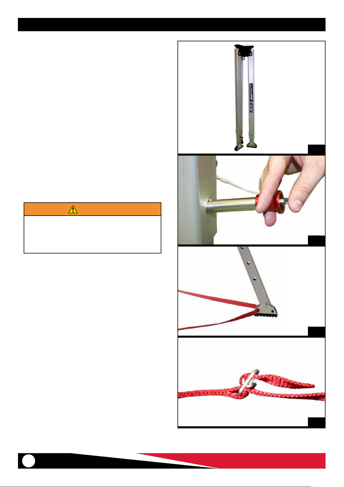
1. Stand the IndustriPOD® upright with legs together (Figure 1).
2. Extend leg lengths to achieve the desired Head height.
3. To extend legs:
a. Remove the leg pins from each leg by depressing the pin
release button at the head of the pin (Figure 2).
b. When legs are extended to desired height, align the holes
on individual leg sections and re-insert the leg pins.
4. Double check all leg pins are locked in place and the tripod is
at the correct height.
5. Move the IndustriPOD® to the desired location and splay legs
over area to required spread width.
6. Thread the leg tether strap through each IndustriPOD® leg foot
(Figure 3).
7. When the foot tether is threaded through all feet holes, join the
ends together to form a loop by feeding the tail end of the foot
tether sling through the buckle and tightening to ensure there
is no slack in the tether (Figure 4).
1
WARNING
Do not attempt to assemble the IndustriPOD® over an
open hole. Erect the IndustriPOD® away from voids
and edges and move it to the required location once
IndustriPOD® legs have been extended and locked into
place with leg pins.
2
3
4
8
© Ferno Australia / 00425-V1 / Aug 2018
Page 9
INSTRUCTIONS FOR USE
3.4 Setting up the IndustriPOD®
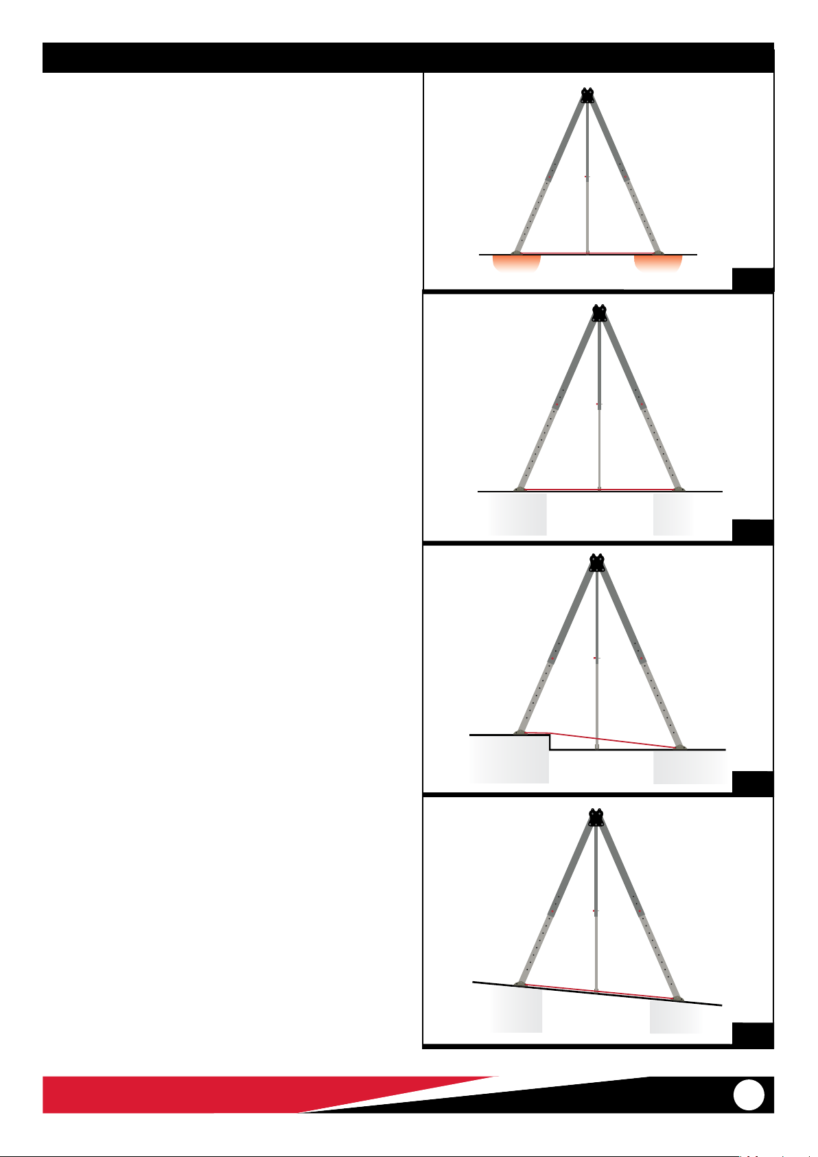
3.4.1 Check the Surface (Figure 5)
● Make sure the substrate or oor below the IndustriPOD®
feet can sustain the anticipated loads.
● Beware of soft ground and unsupported oors. Manage
these accordingly.
3.4.2 Keep the IndustriPOD® head level
● On at surfaces all the legs will be the same length.
● On uneven surfaces the legs can be dierent lengths.
● Adjust the length of one or more legs so the IndustriPOD’s
head is level and directly over the opening or work area.
● Figure 6: Flat surface
● Figure 7: Floor of dierent heights
● Figure 8: Sloping surface
5
6
7
© Ferno Australia / 00425-V1 / Aug 2018
8
9
Page 10
INSTRUCTIONS FOR USE
3.5 IndustriPOD® as a high anchor
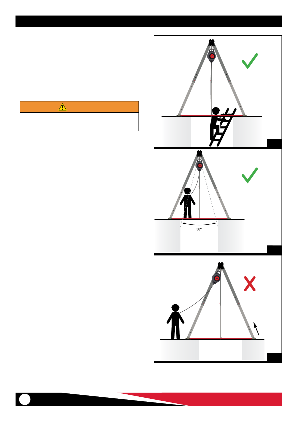
● Example: With a Fall Arrest Block
● Attach the fall arrest block to an anchor point on the IndustriPOD®
head (Figures 9 and 10).
● Keep the load within the IndustriPOD® legs (Figures 9 and 10).
WARNING
Keep the load within the legs. Operating outside the legs
can create a sideways swing and unbalance the tripod.
9
10
11
10
© Ferno Australia / 00425-V1 / Aug 2018
Page 11
INSTRUCTIONS FOR USE
3.6 IndustriPOD® as a change of direction
To use the tripod as a change of direction:
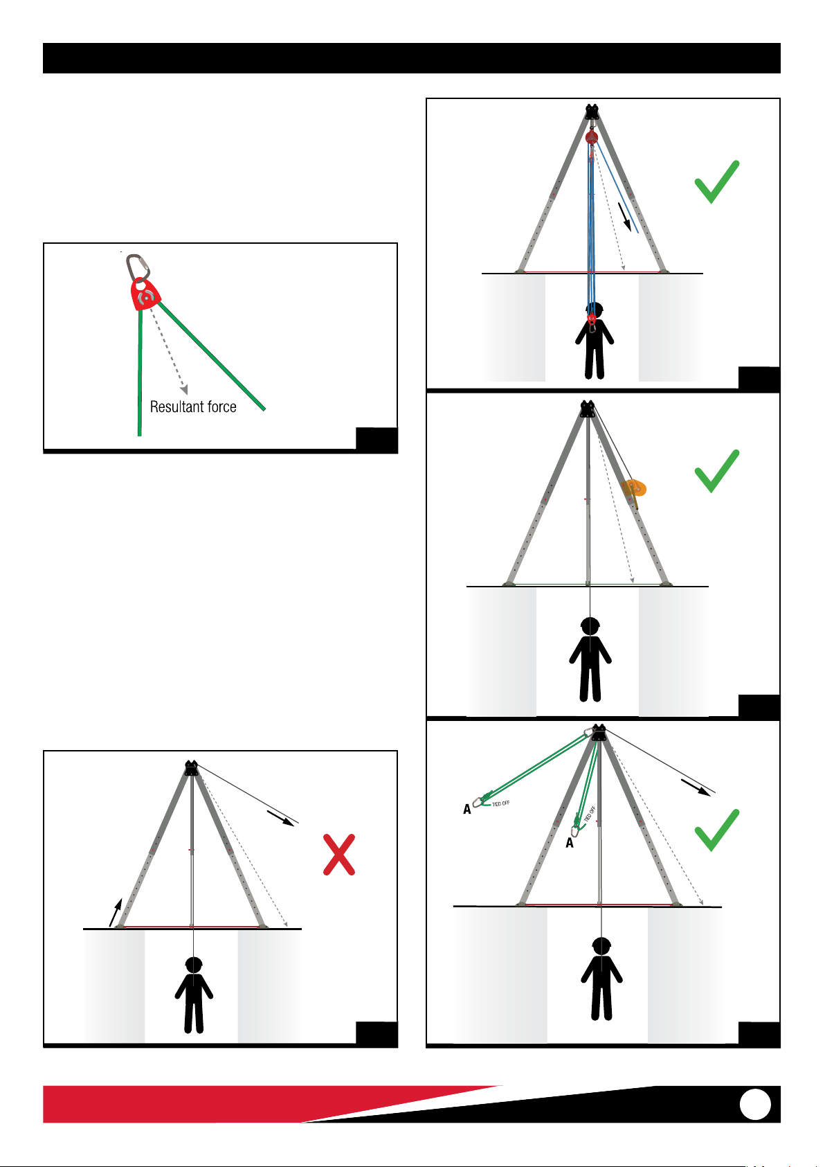
● Use the integrated pulley in the IndustriPOD+® head or
● Attach a pulley to an anchor point on the IndustriPOD+® head.
The resultant force bisects the rope/cable coming into and out of a
pulley (Figure 12).
12
13
The resultant force (indicated by the dashed line) must be kept within
the triangle formed by the feet when there is no stabilisation rigging
as it can unbalance the tripod.
This is achieved by keeping the haul line parallel with the legs.
When pulling away from the legs the resultant force is outside the
tripod triangle. A minimum of two legs must have stabilisation
rigging on the opposite side to the pull.
Refer to Stabilisation Rigging on page 12).
● Figure 13: Pulley system with locking system
● Figure 14: Winch
● Figure 15: Pulling away from the legs with stabilisation rigging
● Figure 16: Pulling away from the legs without stabilisation
rigging
14
© Ferno Australia / 00425-V1 / Aug 2018
16
15
11
Page 12
INSTRUCTIONS FOR USE
3.7 Stabilisation rigging for the head
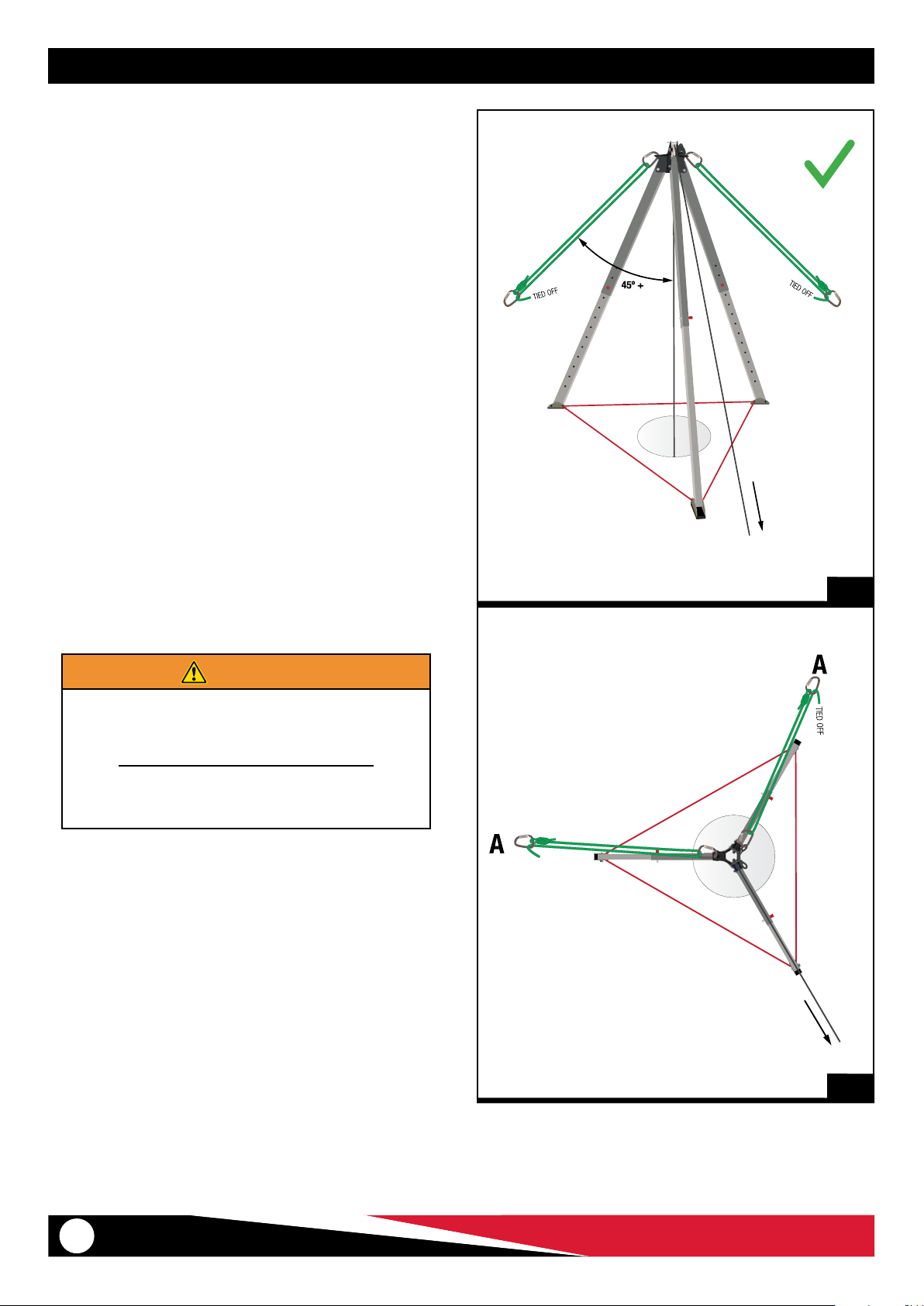
Additional rigging can be used to stabilise the tripod via the head.
The purpose is to manage sideways forces (e.g. change of direction)
or other situations where the tripod may become unstable.
Use the three rigging points on the IndustriPOD® head for stabilisation.
A minimum of two legs must be stabilised with stabilisation rigging
on the opposite side to the pull.
Pull parallel with leg or as closely in-line with leg as possible (Figures
17 and 18).
A number of dierent rigging methods can be used for stabilisation
including:
● 11mm static rope with a 2:1 conguration, tied o.
● A simple ratchet strap system.
When rigging:
1. Apply light tension (not over-tightening) to reduce movement.
2. Ideally spread the rigging out evenly in line with the legs (i.e.
120° apart).
3. Use and rig suitable independent anchors for the stabilisation
rigging.
4. Rigging the anchors o the oor will result in a more stable
tripod.
5. If the feet require stabilising, use an independent tether.
IndustriPOD® Hold-down Stakes (Part # 16-1046-0) are available
as an optional accessory for this purpose. Refer page 16.
A
A
17
WARNING
Ensure anchor points to a structure are capable of
withstanding the impact force generated by a possible
free fall. Attachment/anchor points must be compatible
with the safety line hardware.
Improper stabilisation and rigging of the IndustriPOD®
can cause injury or death. Operators must be competent
and trained in stabilisation techniques.
TIED OFF
TOP VIEW
18
12
© Ferno Australia / 00425-V1 / Aug 2018
Page 13
INSTRUCTIONS FOR USE
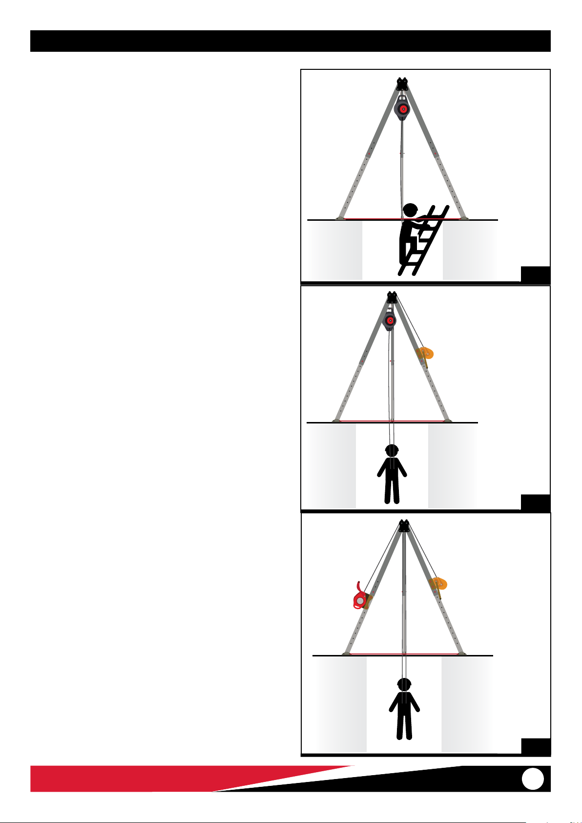
3.8 Two points of contact
Two points of contact with the user is needed for height safety:
(1) a primary means of support and
(2) a backup system.
Options for the primary means of support include a ladder, winch or
pulley system.
A backup is used if the primary means of support fails. Examples of a
back up system include a fall arrest block or winch.
● Figure 19: Primary: Ladder / Backup: Type 2 fall arrest block
● Figure 20: Primary: Winch / Backup: Type 2 fall arrest block
● Figure 21: Primary: Winch / Backup: Type 3 fall arrest block
19
© Ferno Australia / 00425-V1 / Aug 2018
20
21
13
Page 14
INSPECTIONS
4 INSPECTIONS
To maintain the safety and serviceability of this product, regular inspections must be performed.
4.1 Operator Inspection
Each user should be trained in the safe use and inspection of the
product. The product should be inspected by a competent person
before and after each use to ensure it functions correctly and that
all components are safe to use. A checklist is provided below
as a guide that may be used in conjunction with your approved
workplace protocols.
Refer any signs of deterioration to a competent person for a decision
on the safety and serviceability of the product. If in doubt, tag it out!
WARNING
Remove the IndustriPOD® from service if it has been
used to arrest a fall, or if you have any doubt about the
unit’s condition for safe use. Do not use it again until it
has been inspected by Ferno or an appropriately trained,
accredited person and written conrmation provided.
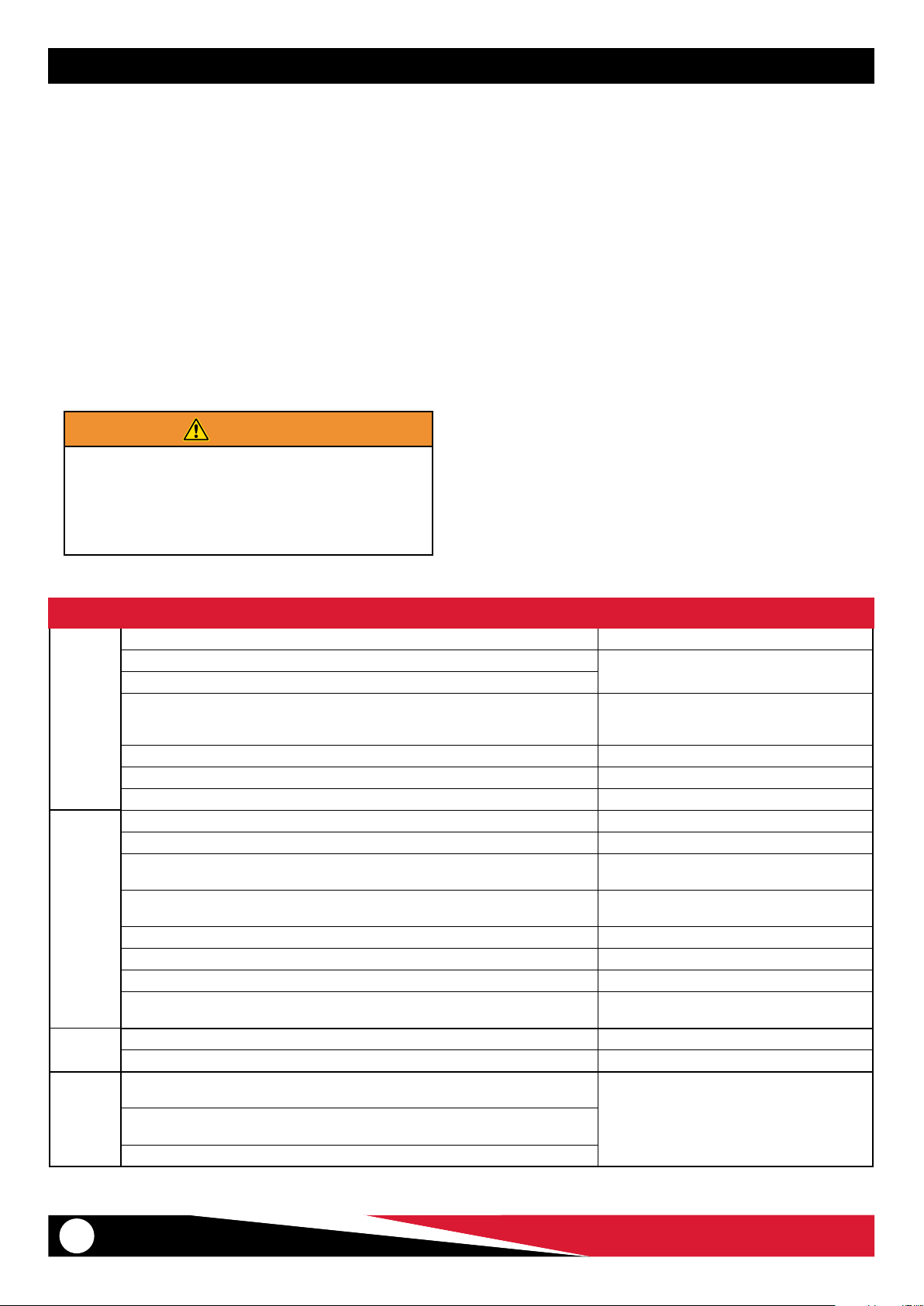
CHECK LIST FOR INSPECTION OF IndustriPOD®
INSPECTION ACTION IF DAMAGED
Any damage such as cracks, dents or gouging?
Do legs extend and retract smoothly?
LEGS &
LEG PINS
HEAD
FEET
FEET
TETHER
Do leg pin holes show obvious damage, gouging, elongation or lower deep indentations
on the pin area?
Do leg pins operate smoothly? Do the ball locks release when the button is depressed? Replace pins if not operating smoothly.
Inspect the cable attaching leg pin to the leg for damage. If damaged, replace the cable.
Is the leg label with load rating information present and legible? Replace if illegible.
Is the Serial Number Label present and legible? Contact Ferno Australia
Is the head securely attached to he tripod legs? Are all fasteners present and tightened? If loose, remove from service for further inspection
Inspect entire head for damage and indentations. Normal wear and tear is acceptable.
Does the eyebolt (if present) swivel? Is the eyebolt’s holding nut weld is intact with no
evidence of tampering? Does it show signs of damage, distortion, cracks?
Do the pulleys (if present) rotate freely with no binding or resistance on the pulley bearings?
Inspect the grooves of the pulley. Is there damage or sharp edges within the sheave?
Are the detent pins secured to the head? Do they operate and insert easily into the holes?
Do detent pins show signs of rust or damage?
Inspect the foot and lashing holes for deformation, damage and sharp edges. If damaged, replace the foot.
Is the polyurethane plastic tread showing signs of damage?
Are there signs of cuts or tears, abrasion damage, excessive stretching, deterioration due to
rotting, mildew or ultraviolet exposure?
contact with heat, corrosives, solvents or mildew?
Is the buckle distorted, cracked or physically damaged?
4.2 Periodic Inspections
● A full periodic inspection should be conducted every six
months by a competent person, or more frequently depending
on frequency of use, environmental conditions or if your
organisation’s protocols dictate. An Inspection Guide is provided
as a reference.
● If any part of the System is to be exposed to harsh chemicals
or hazardous atmospheres, the User/Operator should consult
with Ferno Australia to determine whether the part is suitable
for continued use.
● Periodic inspections should be recorded in the product’s
Inspection and Maintenance log. Refer sample logs on pages 17,
18 and 19.
● It is recommended to write the date of the next inspection on
the device.
● Use the Inspection Checklist as a guide for determining the
condition of the product.
If signs present, remove from service for further
inspection and replacement.
If deep indents greater than 0.5mm are present,
this may indicate the leg has been subjected to
overloading. Remove from service.
If obvious damage is present, return to Ferno or an
authorised agent for repair or replacement
Do not use if damaged.
If rusting, lubricate with a Teon-based spray
lubricant.
Replace if damaged.Is stitching broken or cut? Is there any worn thread or damaged/weakened thread due to
14
© Ferno Australia / 00425-V1 / Aug 2018
Page 15

MAINTENANCE, PARTS & SERVICES
5 MAINTENANCE, STORAGE & TRANSPORT
5.1 Cleaning IndustriPOD®
1. Wash the unit with warm water and soft detergent soap.
2. Rinse with clean water.
3. Air-dry the unpacked unit in a dry, shaded and well-ventilated
area. Do not use additional heat sources or blowers to dry the
unit.
4. Avoid contact with chemicals, oils, solvents and other aggressive
corrosive materials or agents.
5. Once the unit is dry, store it in an appropriate bag or box.
Note: Optional IndustriPOD® Bag (Part # 36-1019) available.
5.2 Storing IndustriPOD®
Store the IndustriPOD® in a clean, dry area away from direct sunlight,
chemicals and corrosive elements.
5.3 Transporting IndustriPOD®
To avoid damage during transport, the IndustriPOD® should be
packed in its bag or an appropriate container / box.
6 SERVICING & PARTS
6.1 Servicing IndustriPOD®
Repair work on the IndustriPOD® may only be carried out by Ferno
Australia or an authorised, accredited agent.
Any other repair work or modications to the product will void its
warranty.
For service or repairs, please contact your local Ferno Distributor or
Ferno Australia.
Tel: +61 7 3881 4999
Email: [email protected]
Website: www.ferno.com.au
6.2 Spare Parts
The following parts are available and may be replaced by the user or
product owner. All other parts must be tted by Ferno Australia or a
trained Ferno-authorised agent.
PART # INDUSTRIPOD® QUANTITY
42-1033 Adjustable Foot Tether 1
51-0081 IndustriPOD® Leg Label 3
51-0112 IndustriPOD+ ® Leg Label 3
WARNING
The IndustriPOD® has been engineered and tested using
the original equipment as supplied. Never replace pins,
bolts or other supplied components with non-genuine
parts
© Ferno Australia / 00425-V1 / Aug 2018
15
Page 16
ACCESSORIES
7 ACCESSORIES
7.1 Optional Accessories
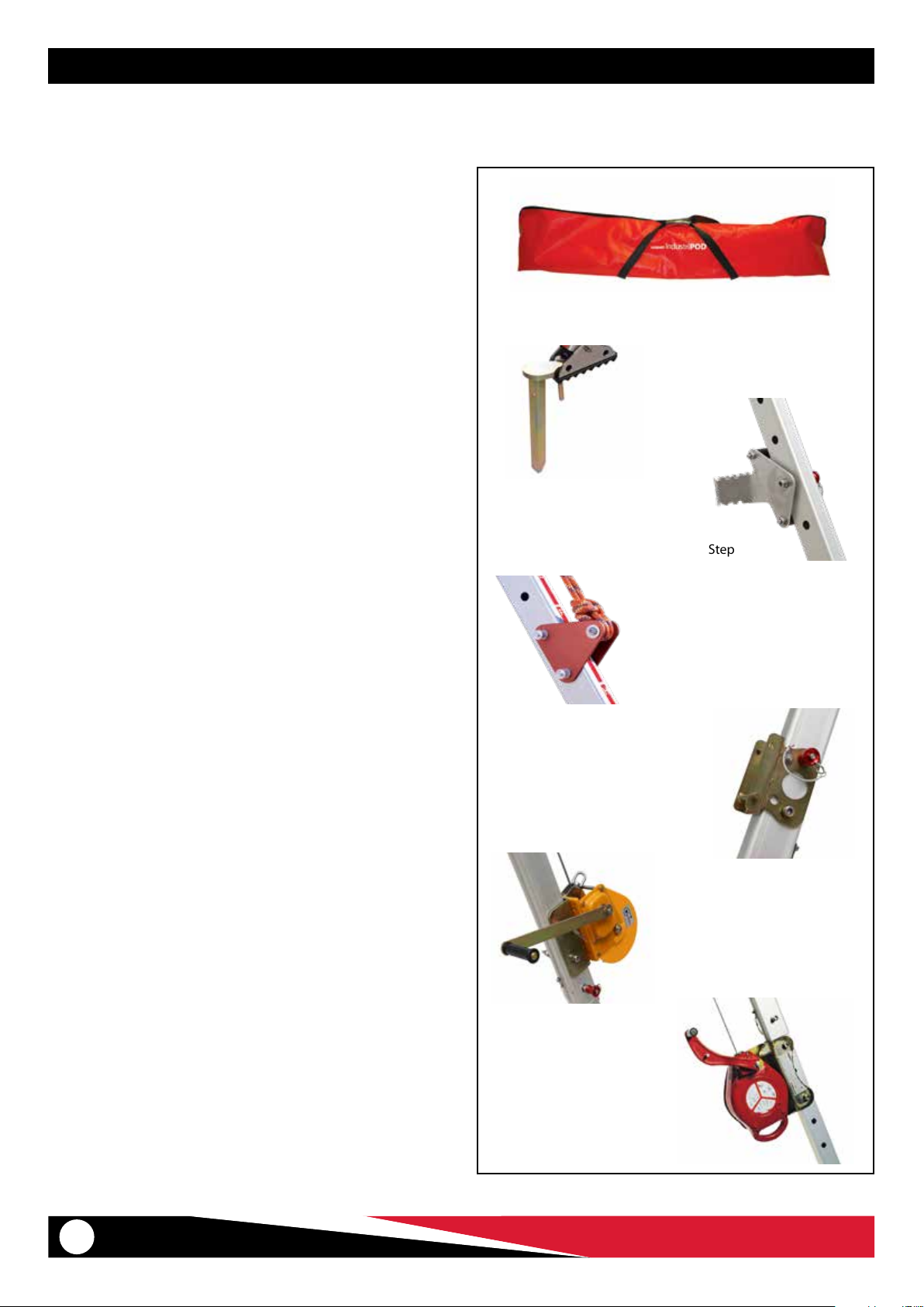
A range of tested and approved accessories is available to enhance
working eciency or extend the versatility of the IndustriPOD®.
INDUSTRIPOD® BAG
A sturdy bag to t the IndustriPOD® and constructed with heavy
duty rip-stop vinyl with integral carry handles and a three-sided zip
for easy removal and packing of IndustriPOD®. Part No. 36-1019
HOLD DOWN STAKE
The Hold Down Stake is designed to secure the IndustriPOD foot . It
is ideal for soft ground applications such as grass.
Part No. 26-2056-0
IndustriPOD® BagIn
Hold Down Stake
STEP
The step is mounted to the lower or middle section of the leg and is
an invaluable aid that enables you to reach the IndustriPOD® head to
adjust rigging after set up. Part No. 07-1026-0
EQUIPMENT BRACKET
Used for rope descenders, belay devices, hauling systems and tying
o rope. Part No. 90-0119
FALL ARREST BLOCK ADAPTOR
Enables a SALA Fall Block to be mounted and used on IndustriPOD®.
Part No. APOD-FBA
WINCH AND MOUNT
A 10m, 20m and 25m Winch with 6mm cable. Supplied with a
bracket mount to t the IndustriPOD® leg.
Part No. APOD-W10/W20/W25
Step
Equipment Bracket
Fall Arrest Block Adaptor
Winch & Mount
TYPE 3 FALL ARRESTOR AND MOUNT
15m Type 3 Fall Arrestor. Supplied with bracket mount to t the
IndustriPOD® Leg. Part No. APOD-FA
16
Type 3 Fall Arrestor & Mount
© Ferno Australia / 00425-V1 / Aug 2018
Page 17

INSPECTION & MAINTENANCE RECORD
8 INSPECTION & MAINTENANCE RECORDS
SUPPLIER
DETAILS
DESIGNATION
MODEL/ITEM # MANUFACTURE DATE
SERIAL # PURCHASE DATE
COMMISSIONED DATE
INSPECTION & MAINTENANCE RECORD
DAT E MAINTENANCE & ACTION TAKEN PARTS REPLACED SIGNATURE NEXT INSPECTION
© Ferno Australia / 00425-V1 / Aug 2018
17
Page 18

SUPPLIER
DETAILS
DESIGNATION
MODEL/ITEM # MANUFACTURE DATE
SERIAL # PURCHASE DATE
COMMISSIONED DATE
INSPECTION & MAINTENANCE RECORD
DAT E MAINTENANCE & ACTION TAKEN PARTS REPLACED SIGNATURE NEXT INSPECTION
18
© Ferno Australia / 00425-V1 / Aug 2018
Page 19
SUPPLIER
DETAILS
DESIGNATION
MODEL/ITEM # MANUFACTURE DATE
SERIAL # PURCHASE DATE
COMMISSIONED DATE
INSPECTION & MAINTENANCE RECORD
DAT E MAINTENANCE & ACTION TAKEN PARTS REPLACED SIGNATURE NEXT INSPECTION
© Ferno Australia / 00425-V1 / Aug 2018
19
Page 20

11 Johnstone Road
Brendale QLD 4500, AUSTRALIA
Emergency
Rescue
Height Safety
Rock Climbing
Mortuary
© Ferno Australia | 00425-V1 | August 2018
 Loading...