

Page 1
Bath,
Whirlpool
NSN
Contract
6530-01-128-2442
Federal
DLA
120-89-C-8515
Supply
Code
16835
Page 2
FERNO
Mobile
Hydrotherapy
Unit
Ne
Operation,
For
ma.
Service
Repair
Manual
Model
200
and
Parts
Page 3
Section
1:
Manual
of
Contents
Section
Section
TOUCH
Electrical
Drawings
Parts
Section
Installation
Start-up
Operator
Shut
Section
Preventive
an
Maintenance
Replacement
Repair
Supplies
ADCESSONESU
Section
1:
2:
Drawings
3:
Down
4:
Procedure
5:
Manual
Equipment
Characteristics
..
Kaleme
.
Data
Maintenance
Maintenance
ーーー
Warranty
of
Contents
Data
E
n
Operation
Procedures
이
Procedures
Parts
so
.....................
....
o
cero
.
..................
and
4 .
de
and
ota
Drawings
cnr
Se
.
Repair
o
de
e
Soda
seca
24
gi
8
44
45
...4.6
4.7
Copyright,
©
Ferno-Washington,
1989,
Inc.
Page 4
Section
2:
Equipment
Data
and
Drawings
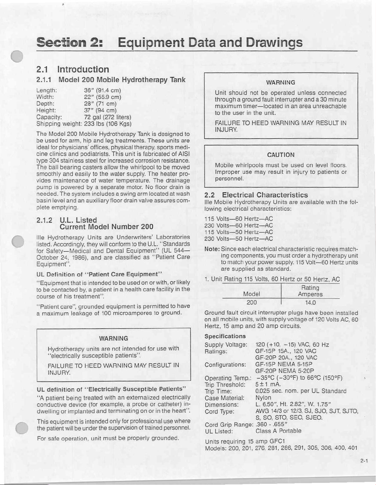
2.1
2.1.1
Length:
Introduction
Model
Width:
Depth:
Height:
Capacity:
Shipping
The
Model
be
used
for
ideal
cine
type
The
smoothly
vides
pump
needed.
basin
plete
2.1.2
1116
listed.
for
October
Equipment”.
UL
“Equipment
to
course
“Patient
a
UL
“A
conductive
dwelling
This
the
For
physicians’
clinics
304
ball
maintenance
is
level
emptying.
Hydrotherapy
Accordingly,
Safety—
Definition
be
contacted
of
maximum
Hydrotherapy
“electrically
FAILURE
INJURY.
definition
patient
equipment
patient
safe
200
36"
22"
28"
37"
72
weight:
for
stainless
bearing
and
powered
The
U.L.
Current
24,
his
care’,
or
will
operation,
233
200
Mobile
arm,
hip
and
podiatrists.
steel
casters
easily
by a separate
system
and
an
auxiliary
Listed
Units
they
Medical
1986),
of
“Patient
that
is
intended
by, a patient
treatment”.
grounded
leakage
units
susceptible
TO
HEED
of
‘Electrically
being
treated
device
implanted
is
intended
be
under
Mobile
(91.4
(559
(71
(94
gal
(272
Ibs
Hydrotherapy
and
offices,
for
to
the
of
water
includes a swing
Model
will
and
and
of
100
WARNING
are
WARNING
(for
example, a probe
and
the
unit
must
Hydrotherapy
cm)
cm)
cm)
cm)
liters)
(106
Kgs)
leg
treatments.
physical
This
increased
allow
the
water
temperature.
floor
drain
Number
are
Underwriters’
conform
Dental
are
classified
Care
to
be
in a health
equipment
microamperes
not
intended
patients”.
Susceptible
with
an
terminating
only
for
supervision
be
Tank
is
These
therapy,
unit
is
fabricated
corrosion
whirlpool
supply.
motor.
The
No
arm
valve
The
located
assures
200
to
the
U.L.
Equipment’’
as
“Patient
Equipment”
used
on
or
care
is
permitted
to
for
MAY
RESULT
externalized
or
on
or
professional
of
trained
properly
grounded.
Tank
designed
sports
resistance.
to
be
heater
drainage
floor
Laboratories
"Standards
(UL
with,
facility
ground.
use
Patients”
electrically
catheter)
in
the
use
personnel.
units
medi-
of
AISI
moved
pro-
drain
at
wash
com-
544
Care
or
likely
in
to
have
with
IN
heart”.
where
to
are
is
一
the
in-
Unit
should
through a ground
maximum
to
the
user
FAILURE
INJURY.
Mobile
Improper
personnel.
2.2
Electrical
Ille
Mobile
lowing
115
Volts—60
230
Volts—60
115
Volts—50
230
Volts—50
Note:
Since
ing
to
are
1.
Unit
Ground
on
all
mobile
Hertz,
15
Specifications
Supply
Ratings:
Configurations: © GF-15P
Operating
Тир
Threshold: © 5+1
Třip
Time:
Case
Material:
Dimensions:
Cord
Type:
Cord
Grip
UL
Listed:
Units
requiring
Models:
TO
whirlpools
use
Hydrotherapy
electrical
each
components,
match
supplied
Rating
fault
circuit
units,
amp
Voltage:
Temp.:
Range:
200,
201,
WARNING
not
be
operated
fault
interrupter
timer—located
in
the
unit.
HEED
WARNING
CAUTION
must
be
may
result
Characteristics
Units
characteristics:
Hertz—AC
Hertz—AC
Hertz—AC
Hertz—AC
electrical
your
power
as
115
Volts,
Model
200
interrupter
with
and
20
120
GF-15P
GF-20P
GF-20P
—35%C
0.025
Nylon
L.
AWG
S,
.360 - .655”
Class A Portable
15
amp
276,
characteristic
you
must
supply.
standard.
60
Hertz
supply
amp
circuits.
(+10,
15A.,
20A.,
NEMA
NEMA
(—309F)
mA.
sec.
6.50”,
Ht.
14/3
SO,
STO,
GFC1
281, 286,
—15)
or
unless
in
an
area
used
in
injury
are
available
order a hydrotherapy
115
or
Amperes
plugs
voltage
VAC,
120
120
5-15P
5-20P
to
nom.
2.82”,
12/3,
SEO,
291,
connected
and a 30
unreachable
MAY
RESULT
on
level
to
patients
requires
Volt—60
50
Hertz,
Rating
140
have
been
of
120
60
VAC
VAC
66°C
per
UL
W.
1.75”
SJ,
SJO,
SJEO.
305,
minute
with
Volts
Hz
(150ºF)
Standard
306, 400,
IN
floors.
or
the
match-
Hertz
units
AC
installed
AC,
SJT,
SJTO,
fol-
unit
60
x
401
2-1
Page 5
CAUTION
Incorrect
equipment.
match
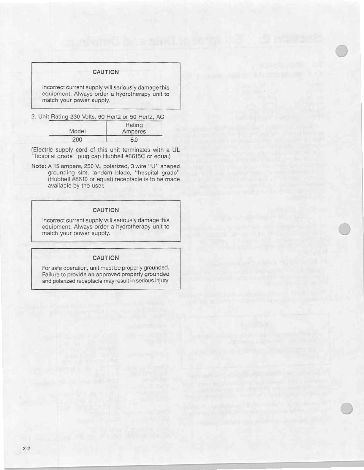
2.
Unit
Rating
(Electric
“hospital
Note: A 15
supply
grounding
(Hubbell
available
Incorrect
equipment.
match
For
safe
Failure
and
polarized
current
Always
your
power
230
Model
200
cord
grade”
plug
ampere,
slot,
#8610
by
current
Always
your
power
operation,
to
provide
receptacle
supply
Volts,
will
seriously
order a hydrotherapy
supply.
60
Hertz
of
this
unit
cap
Hubbell
250
V.,
polarized, 3 wire
tandem
or
equal)
the
user.
CAUTION
supply
order a hydrotherapy
supply.
CAUTION
unit
an
approved
will
must
may
blade,
receptacle
seriously
be
result
damage
or
50
Hertz,
Rating
Amperes
60
terminates
48615C
properly
properly
or
“U”
"hospital
is
damage
grounded.
grounded
in
serious
this
unit
to
AC
with a UL
equal)
shaped
grade”
to
be
made
this
unit
to
injury.
2-2
Page 6
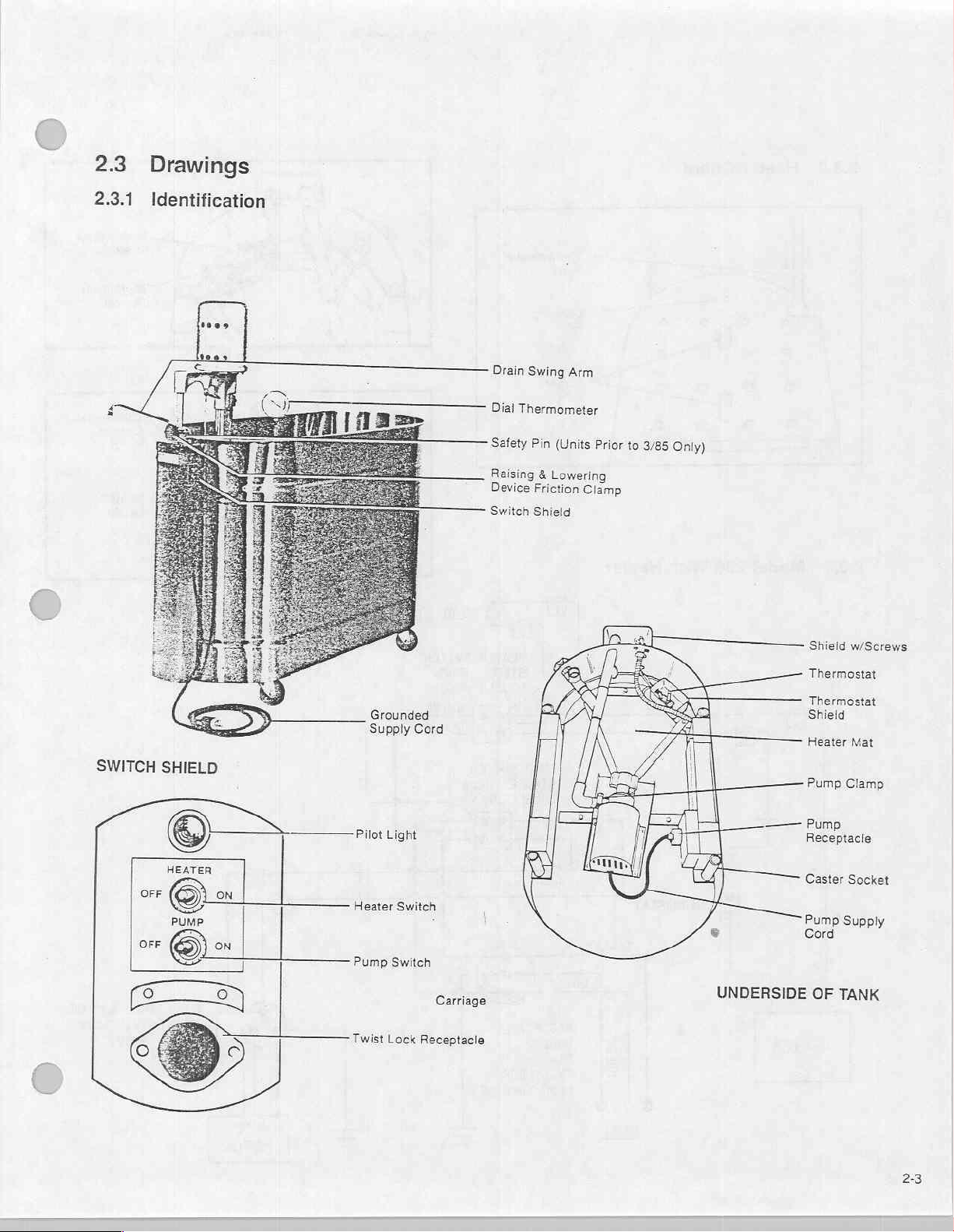
2.3
Drawings
2.3.1
ma
Identification
=
=
maias
Drain
Swing
Arm
——
Dial
Thermometer
Safety
Pin
(Units
Prior
Raising & Lowering
Device
Switch
Friction
Shield
Clamp
to
3/85
Only)
Shieid
w/Screws
SWITCH
ME
Fi
on
OFF
SHIELD
HEATER
(Oro
PUMP
©
=
ON
|
|
¡
Grounded
Supply
Pilot
Light
Switch
Heater
Pump
Switch
Twist
Lock
Cord
i
i
Carriage
Receptacle
一 一 Pump
UNDERSIDE
Thermostat
Thermostat
Shield
Heater
Mat
Pump
Clamp
Receptacle
Caster
Socket
Pump
Supply
Cord
OF
TANK
23
Page 7
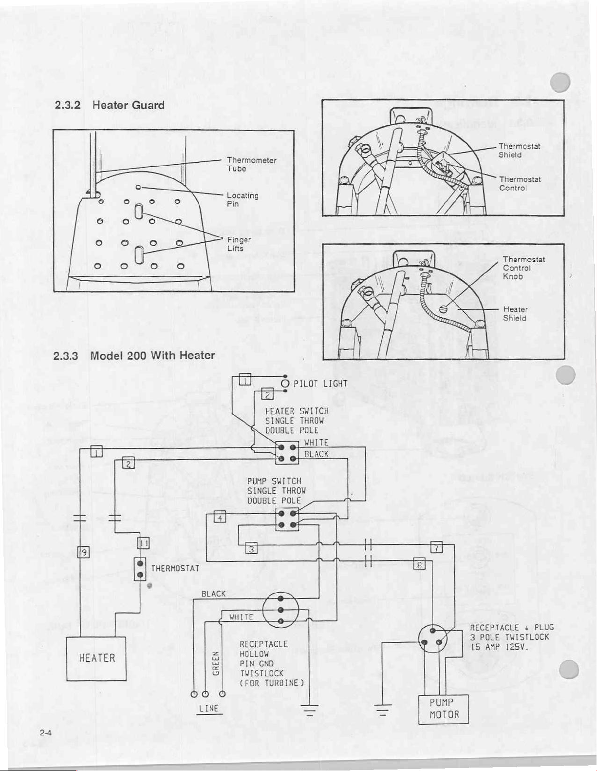
2.3.2
Heater
Guard
Thermometer
Tube
Locating
Pin
Thermostat
Shiel
red
Thermostat
Control
2.3.3
—
Bl
回
Model
El
+
№
200
団
η
a
le]
With
Heater
THERMOSTAT
=
A
Finger
Lifts
=
PUMP
SINGLE
DOUBLE
O
HEATER
SINGLE
DOUBLE
po
©
19
©
SWITCH
THROW
POLE
e
ee
о
PILOT LIGHT
SWITCH
THROW
POLE
MHITE
BLACK
т
|
Thermostat
Control
Knob
Heater
Shield
24
HEATER
‘
BLACK
RECEPTACLE
HOLLOW
PIN
GND
TWISTLOCK
(FOR
TURBINE)
PUMP
MOTOR
RECEPTACLE s PLUG
3
POLE
15
AMP
TWISTLOCK
125V.
Page 8
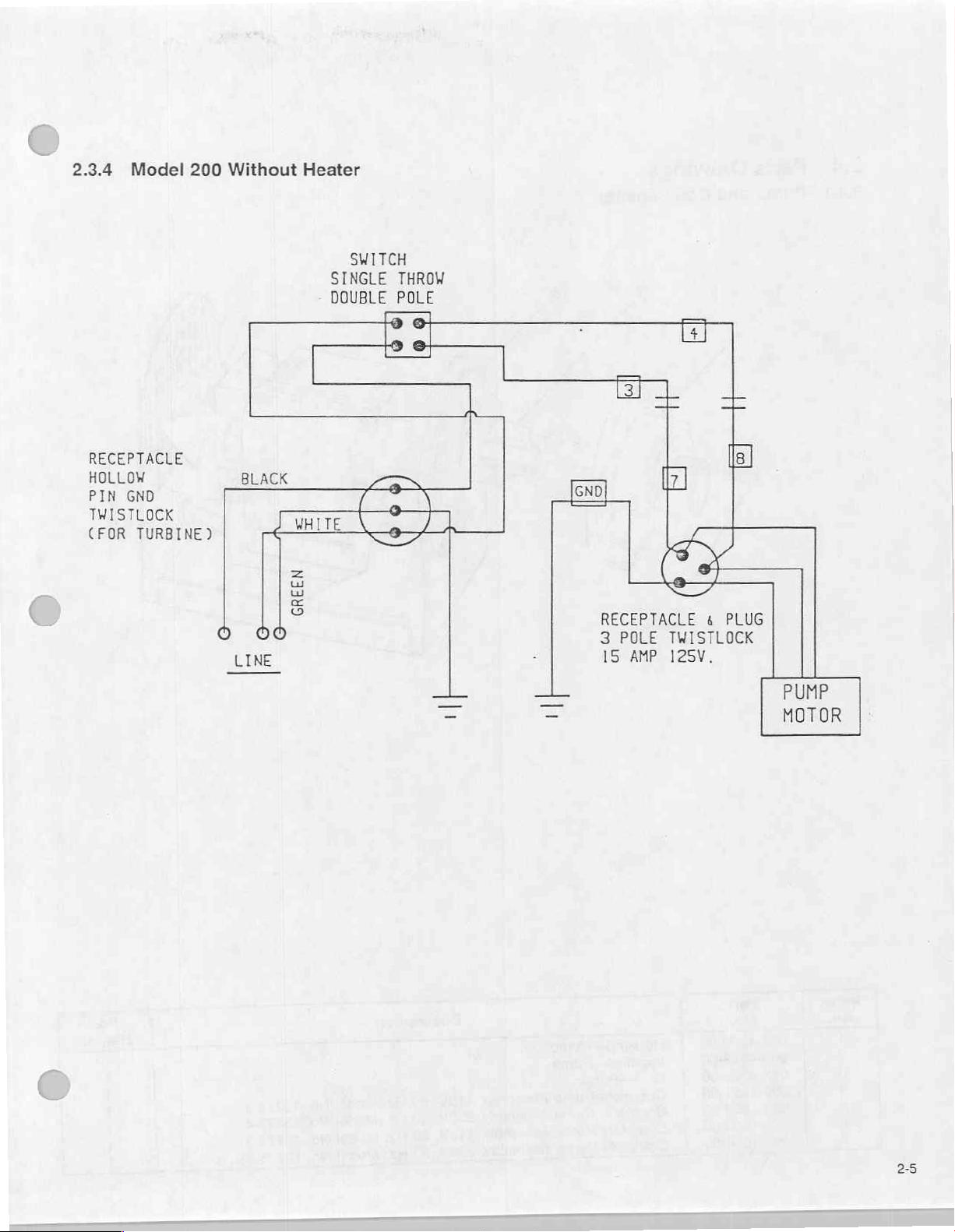
2.3.4
Model
RECEPTACLE
HOLLOW
PIN GND
TWISTLOCK
(FOR
TURBINE)
200
Without
Heater
SWITCH
SINGLE
DOUBLE
THROW
POLE
©
Se
RECEPTACLE & PLUG
LINE
3
15
POLE
AMP
TWISTLOCK
125V.
PUMP
MOTOR
25
Page 9
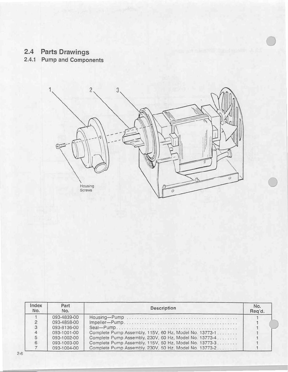
2.4
2.4.1
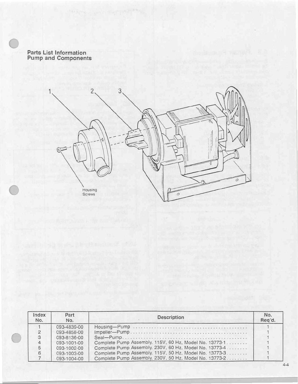
Parts
Pump
Drawings
and
Components
Housing
Screws
26
NR
4
2
3
4
5
6
η
093-4839-00
093-4858-00
093-8136-00
093-1001-00
093-1002-00
093-1003-00
093-1004-00
Housing—Pump
Impeller—Pump
Seal—Pump
Complete
Complete
Complete
Complete
Pump
Pump
Pump
Pump
...
Assembly,
Assembly,
Assembly,
Assembly,
Description
ο
115V,
60
Hz,
230V,
60
Hz,
115V,
50
Hz,
230V,
50 Hz,
Model
Model
Model
Model
a
No.
13773-1........
No.
13773-4..
No.
13773-3.
No.
13773-2
1
1
1
1
1
1
1
Page 10
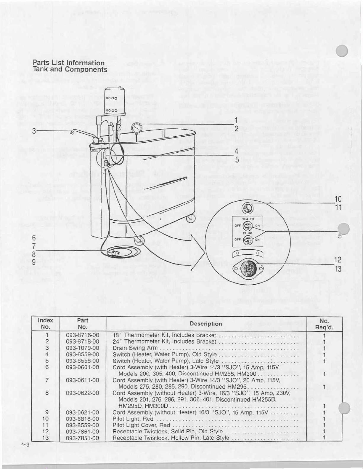
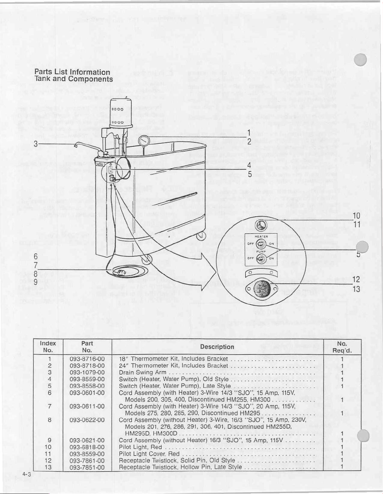
Parts
Tank
List
Information
and
Components
ㅇㅇ
index
43
Я
2
3
4
5
6
7
8
9
10
11
12
13
č
093-8716-00
093-8718-00
093-1079-00
093-8559-00
093-8558-00
093-0601-00
093-0611-00
093-0622-00
093-0621-00
093-6818-00
093-8559-00
093-7861-00
093-7851-00
18”
Thermometer
24”
Thermometer
Drain
Swing
Switch
Switch
Cord
Assembly
Models
Cord
Assembiy
Models
Cord
Assembiy
Models
HM205DIFMA0OD
Cord
Assembly
BiletLight,
Pilot
Light
Receptacle
Receptacle
Arm
(Heater,
(Heater,
Water
Water
(with
200,
305, 400,
(with
275,
280,
(without
201,
276,
(without
Red...
Cover,
Twistlock,
Twistlock,
Kit,
Includes
Kit,
Includes
Pump),
Pump),
Heater)
Heater)
285, 290,
286,
Red
.....
Solid
Hollow
Description
Bracket
Bracket
Old
Style...
Late
Style . .
3-Wire
Discontinued
3-Wire
Discontinued
Heater)
291,
τς
Heater)
306,
Pin,
Pin,
3-Wire,
401,
16/3
Old
Late
...
.
14/3
‘‘SJO",
HM255,
14/3
Discontinued
o
‘“SJO",
Style
Style
HM300.............
“SJO”,
HM295
16/3
“SJO”,
RE
15
..
15
20
Amp,
Amp,
115V,
Amp,
115V,
15
Amp,
HM255D,
115V
..
23
Ότο.
.
4
V,
mba
E
og
1
1
1
1
1
À
1
1
1
1
1
1
1
Page 11
Section
3:
Equipment
Operation
3.1
3.1.1.
1.
2.
3.
Installation
Unpacking
Remove
and
Now
ducts,
Refer
outer
carefully
remove
and
any
to
Turbine
remove
turbine
carton
small
accessories
Manual
(pull
nails
inner
packing
ejector,
for
from
base;
material.)
samples
installation
from
of
Ferno
the
packing
instructions.
cut
bands
Ille
pro-
shelf.
WARNING
UNITS
Counterbalance
Mount
knob.
ing
FAILURE
INJURY
3.2
3.2.1
Have
receptacle
as a minimum
A.
For
A
lel
is
В.
For
A
straight
turbine
Tighten
turbine.
TO
TO
Start-Up
Electrical
your
professional
in
accordance
requirement.
all
115
Volt
“hospital
blade
required.
all
"hospital
grade”
receptacle
115
Voit
blade
AFTER
tube
before
friction
HEED
PATIENT
3/85
is
gas-cylinder
loosening
clamp
WARNING
OR
PERSONNEL.
Procedures
electrician
with
the
units—15
units—over
grade” 3 wire,
receptacle
wire,
“U”
(Hubbell
amps,
15
(Hubbell
ONLY
knob
MAY
supply
national
or
ground,
#8200
amps
"U”
ground,
activated.
friction
before
remov-
RESULT
and
install a wall
electrical
less
15A-125V.,
or
#8310
#8310
or
clamp
IN
code
paral-
or
equal)
20A-125V.,
equal)
is
required.
C.
For
all
230
Volt
units
A
“hospital
tandem
required.
grade” 3 wire,
blade
receptacle
"U”
(Hubbell
ground,
#8610
15A-250V.,
or
equal)
is
CAUTION
3.2.2
1.
2.
.
3.23
Preparing
Clean
tank.
Adial
thermometer
tank
wall
be
rotated
nylon
thumbscrew
screw
in
Fill
tank
within 5 inches
for
attachment
ing
temperature.
If
water
aged
if
Thermostatically
Operation
1.
The
thermostatically
vided
primarily
water
preliminary
if
there
Temperature
during
Note:
The
maintenance
temperature
.
The
thermostat
imate
maximum
readily
set
for
operation
ment
may
conditions.
Your
electric
in
the
tank.
trol
to
minimize
nents
will
A
red
pilot
cates
when
at
our
in
any
locked
with
warm
from
to
is
mixed
it
comes
is a delay
of
an
average
electric
controls
adjusted
be
required
(Refer
heater
Although
be
reduced.
light,
the
Tank
Unit
has
been
plant.
The
tube
convenient
in
bracket.
position
faucet.
water,
top
of
to
tank. A filler
Use
CAUTION
in
tank,
thermometer
in
contact
controlled
for
making
to
treatment.
in
preparing
the
water
remains
20
minute
heater
from
of
in
the
at
approximately
to
excessive
located
heater
is
heater.
110°F.
page
is
It
cold
water
Range
field.
to
compensate
2-5
not
intended
the
thermostat
heating,
in
switch
mounted
and
thermometer
position
prevent
at
desired
by
After
rattling
adjusting,
temperature,
hose
thermometer
will
with
water
over
Controlled
electric
up
heat
losses
This
is
especially
the
patient
relatively
treatment
only
intended
is
not
able
to
to
treatment
temperature
of
thermostat
All
thermostats
105°F. A slight
for
for
adjustment
for
use
will
the
life
the
unit
switch
has
been
onto
the
inner
may
loosening
keep
of
tube.
is
provided
for
check-
be
dam-
160°F.
Heater
heater
for
period.
raise
without
serve
turned
is
of
the
tepi
81486
treatment.
constant
for
use
as
the
water
temperature.
at
an
approx-
can
are
factory
adjust-
varying
instructions).
field
water
as a con-
of
all
compo-
shield,
indi-
on.
the
to
pro-
>
a
be
3-1
Be
sure
ing
are
nections
to
patient
polarity
correct.
to a
receptacle
and
operator.
and
grounding
Incorrect
may
of
polarity
result
receptacle
and
ground
in
serious
wir-
con-
injury
Page 12
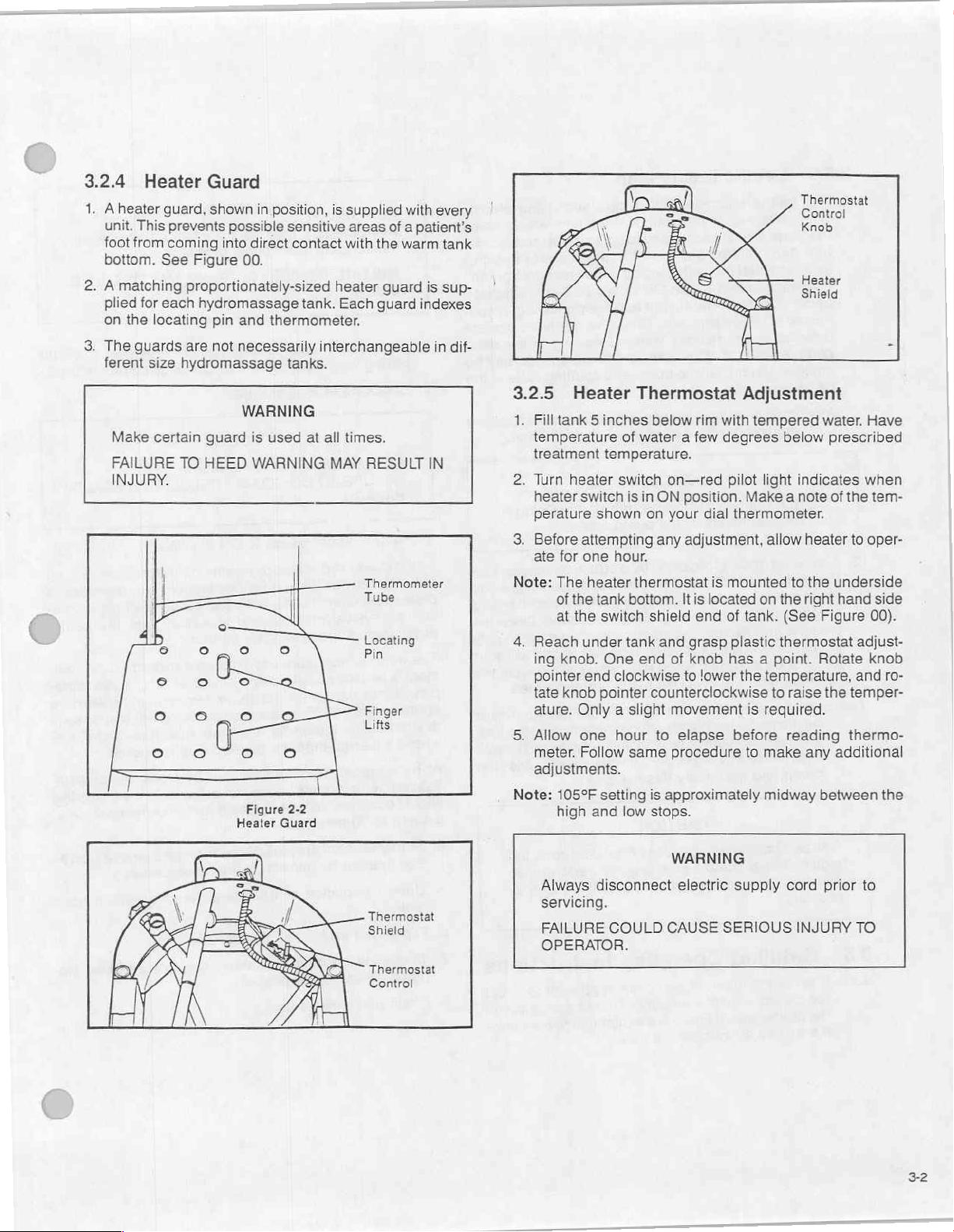
3.2.4
1. A heater
2. A matching
3.
Heater
Unit.
This
foot
from
bottom.
plied
for
on
the
The
guards
ferent
Make
FAILURE
INJURY.
guard,
prevents
coming
See
each
locating
size
certain
Guard
shown
Figure
proportionately-sized
hydromassage
are
hydromassage
guard
TO
HEED
in
possible
into
direct
00.
pin
and
thermometer.
not
necessarily
WARNING
is
used
WARNING
Figure
Heater
position,
sensitive
contact
tank.
interchangeable
tanks.
at
all
MAY
2-2
Guard
is
supplied
areas
with
heater
Each
times.
RESULT
Thermometer
Tube
Locating
Pin
Finger
Lifts
with
every
of a patient's
the
warm
tank
guard
is
sup-
guard
indexes
in
dif-
IN
3.2.5
1.
2.
3.
Note:
4,
5.
Note:
Heater
Fill
tank 5 inches
temperature
treatment
Turn
heater
heater switch
perature
Before
ate
for
The
of
the
at
the
Reach
ing
knob.
pointer
tate
knob
ature.
Only a slight
Allow
meter.
adjustments.
105°F
high
Thermostat Adjustment
of
water a few
temperature.
switch
is
in
shown
attempting
one
heater
tank
under
end
one
Follow
and
on
hour.
thermostat
bottom.
switch
pointer
setting
shield
tank
One
end
clockwise
counterclockwise
hour
same
is
low
stops.
below
rim
with
degrees
on—red
ON
position.
your
dial
any
adjustment,
is
It
is
located
end
and
grasp
of
knob
to
lower
movement
to
elapse
procedure
approximately
WARNING
Thermostat
Control
Knob
Heater
Shield
tempered
below
pilot
light
indicates
Make a note
thermometer.
allow
heater
mounted
of
tank.
plastic
has a point.
the
before
to
on
the
right
(See
thermostat
temperature,
to
raise
is
reguired.
reading
to
make
any
midway
water.
prescribed
of
the
to
the
underside
hand
Figure
Rotate
the
temper-
thermo-
additional
between
Have
when
tem-
oper-
side
00).
adjust-
knob
and
ro-
the
Thermostat
Shield
Thermostat
Control
Always
servicing.
FAILURE
OPERATOR.
disconnect
COULD
electric
CAUSE
supply
SERIOUS
cord
INJURY
prior
TO
to
3-2
Page 13
3.2.6
1.
The
pump
the
turn
sink,
on
under
nected
draining
pump
emptied
same
2.
Aswith
unit
DO
will
3.
The
thermal
to
the
a
dangerously
circuit
cooled
again
continue
Note:
When
and
Gauze,
eign
and
possible.
3.3
Note:
Electric
unit
is
equipped
attached
water
at a
rate
swing
drain
and
start
motor
switch
the
to
shield
base
the
pump
of
any
system.
faster
time.
all
centrifugal
with
liquid
NOT
operate
reduce
pump
be
If
permitted
pump
the
motor
cut-out.
motor
by
is
interrupted,
or
circuit
and
stop
until
the
salt
solutions
drained
pump
immediately
system
and
eventually
‘‘band-aids’’,
matter
are
should
be
Detailed
It
is
not
the
the
clinical
the
the
proper
quality
use
Drain
to
Pump
with a quick-emptying
the
bottom
according
nozzle
to
of
tank,
residue
If
floor
by
using
before
until
by
piacing switch
the
ON
with
drain.
This
water
drain
pump
pumps,
pumping
CAUTION
pump
when
life
of
the
pump
is
protected
This
thermal
automatically
high
temperature
the
motor
resets
itself.
again
when
overload
are
used,
after
should
to
remain,
the
destroy
CAUTION
bandage
detrimental
removed
from
Operating
intent
of
Ferno
care
of
your
of
Ferno
of
your
clinical
of
the
tank
which
to
tank
size. To
it
projects
empty
over
marked
position. A valve
hand
grip
showing,
valve
permits
remaining
is
available,
and
opening
itis
necessary
will
tank
is
in
tank
valve
commence.
dry.
Doing
seal.
by a built-in
cut-out
breaking
will
However,
overheated.
has
been
the
treatment,
be
flushed
salt
clips,
to
pump
patient
automatic
prevents
the
is
reached.
not
start
motor
This
eliminated.
residue
with
solution
it.
will
and
other
performance
as
circuit
and
fresh
much
Instructions
Ille
to
attempt
patient
Ille
but
to
equipment
care.
advise
to
electric
drains
tank,
basin
“pump”
located
is
complete
the
drain
may
at
to
flood
so
damage
before
Once
again
will
cycle
water
the
water.
attack
for-
as
to
direct
you
maximize
or
con-
be
the
the
reset
the
until
start
will
must
tank
the
in
WARNING
Hydrotherapy
“electrically
FAILURE
units
susceptible
TO
HEED
are
not
patients”.
WARNING
intended
MAY
for
use
RESULT
with
IN
INJURY.
1.
2.
Fill
tank
mixing
Check
with
valve
water
water
to
desired
operations
temperature.
treatment
manual
level.
for filling
procedures.)
(Consult
CAUTION
Always
FAILURE
verify
TO
water
DO
SO
temperature.
MAY
RESULT
IN A SCALD
HAZARD.
3.
Flip
the
heater
When
giving
patient
dependent
tient's
physiology
The
ment
pist.
approximately
desired
where a thermo-therapeutic
All
desired
should
usually
4,
5.
must
upon
physical
of
water
temperature
is
usually
It
can
to
the
hydrotherapy
temperature
continue
20-30
Start
treatment
tion
manual
Upon
completion
switch
hydrotherapy
be
taken
into
the
patient’s
and
medical
the
area
specified
vary
from
65°F,
where a cryotherapeutic
higher
treatments
throughout
minutes.
process.
for
correct
of
to
ON
position.
treatment,
consideration.
subjective
condition,
to
be
treated.
used
during a hydrotherapy
by a physician
the
lower
temperature
temperature
response
should
range
the
Refer
spectrum,
be
is
established.
duration
to
turbine
operating
treatment,
remove
the
tolerance
This
tolerance
feelings,
and
or
physical
is
desired.
monitored
of
the
the pa-
the
spectrum,
response
96°-104°F,
until
Monitoring
treatment,
ejector
procedures.
patient
of
the
is
path
treat-
thera-
is
the
opera-
from
=
tank.
6.
Flip
7.
8.
heater
To
drain
pump
Clean
switch
water
switch
and
sanitize
from
to
ON
to
OFF
tank,
move
position.
tank.
position.
unit
to
drain
area,
flip
33
Page 14
3.4
1.
Electric
The
matic
vents
the
reached.
not
However,
heated.
been
Shutdown
drain
pump
electric
circuit
restart
drain
reset
thermal
damage
to
before a dangerously
Once
the
again
motor
This
cycle
eliminated.
Procedures
pump
is
protected
cut-out.
the
motor
circuit
is
until
cooled
will
start
and
will
continue
by a built-in
This
thermal
by
automatically
high
temperature
interrupted,
or
circuit
stop
again
until
the
cut-out
breaking
the
motor
resets
when
overload
auto-
pre-
is
will
itself.
over-
has
34
Page 15
Seciion
4:
Maintenance
and
Repair
4.1
Note:
This
increased
metal.
Foreign
in
ated
and
ally
marks
Even
logical
tamination
procedures.
pool
and
changed
then
Disinfectant
The
be
Preventive
Please
Failure
unit
is
fabricated
corrosion
Cleaning
matter
the
form
of
by
body
other
foreign
the
foreign
in
the
more
important
infection
of
Treatment
Antiseptic
common
completely
be
cleaned
and
acid-alkaline
approximately
If
chlorides
trations
the
sion.
for
for
major
However,
stainless
chlorine.
Remove
4.2
4.2.1
Use
instructions
tion.
hot
Note:
hair
Cleaning
Routine
Sanizene
for
With
soft
water.
When
on
the
infecting
Maintenance
carefully
to
is
is
film
oils,
particles
surface
problems
water,
to
sense
and
are
the
cause
and
Hard
use
cloth,
disinfecting
disinfectant
procedures.
read
observe
of
resistance.
required
deposited
every
time
minerals
matter.
of
the
than
equipment
water
maintain
dictate
after
sanitized
rinsed
balance
with
7.4-7.8
CAUTION
used,
intended
of
pitting
Chlorazene
steel
because
debris
Cleaning
Surface
on
container),
wipe
CAUTION
AISI
If
will
each
of
for
maintain
from
container
these
important
instructions
type
304
However,
for
it
to
keep
onto
your
it
is
used.
in
the
water,
film
is
left
cause
corrosion,
stainless
appearance
that
may
develop
and
inappropriate
may
include
low
bacterial
that
the
treatment.
with
Sanizene
hot
water.
the
water
best
corrosion
the
purpose.
and
Disinfectant
entire
the
tank,
Chloride
intergranular
has
been
of
its
drain
after
soap
surface
consult
for
instructions.
will
void
stainless
it
is
its
polished
stainless
The
film
organic
on the
tank,
steel.
are
the
through
Chlorazene
levels.
water
The
Hard
in
your
tanks
resistance.
lowest
concen-
ions
tested
slow
release
each
in
solution
or
detergent
area.
the
proper
use
warranty.
steel
for
not a magic
look.
steel
tank
is
gener-
deposits,
eventu-
leaving
treatment
pit
bacterio-
con-
Whirl-
Experience
should
tank
be
should
Surface
should
are
corro-
safe
of
use.
(see
in
solu-
Rinse
with
directions
and
dis-
To
Remove
Use a good
and
vinegar.
steel
wool
5
minutes.
Note:
Rinse
Stubborn
stainless
Scrub
or
cleaning
Rinse
Always
mum
thoroughly
rub
effectiveness.
steel
the
with
in
the
with
Spots
and
cleanser
area
with a cloth,
pad.
Let
warm
water
direction
fresh
water
Stains
such
stand
and
of
polish
after
as
Ille
Steelscrub
sponge,
for
approximately
wipe
dry.
lines
every
operation.
Always
NEVER
4.3
4.3.1
When
nozzle,
discharge
1.
2.
wipe
dry
to
avoid
USE
STEEL
High
concentrations
chlorite
affect
will
the
warranty.
damage
Maintenance
Drain
Refer
cian
or a qualified
water
it
Be
sure
Turn
pump
pump. A vibration
If
so,
follow
Probe
nozzle
Put
water
found,
counterflushing
(use
safety
filler
hose
hose
to
slow
flow),
floor.
Rotate
valve
step
4.)
Pump
electrical
fails
to
is
usually
piping.
pump
operates
switch
step
into
swing
was
clogged,
in
tank
the
problem
lock
to
swing
cold
water
and
tank
under
tank.
servicing
flow
due
can
2.
drain
and
drain
pin).
any
to
water
WOOL.
WARNING
of
sodium
your
CAUTION
service
or
runs slowly
to
an
when
ON,
reach
be
detected
If
not,
nozzle
you
probably
try
pump.
is
in
another
pump
Turn
tank
arm
nozzle.
supply.
small
normal
(Should
marks.
or
calcium
hydrotherapy
tank
Procedures
to a professional
technician.
out
of
obstruction
pump
under
follow
with a piece
part
system.
upside
Connect
Open
particles
position,
counterflushing
in
switch
tank
if
pump
step
3.
found
the
If
no
obstruction
of
the
Remove
down.
faucet
will
and
the
of
other
slightly
be
hypo-
electri-
swing
is
turned
and
is
wire.
obstruction.
system.
Attach
flushed
open
fail,
stainless
for
maxi-
cleaning
and
drain
pump
or
on.
touch
running.
If
the
was
Try
turbine
your
end
of
(very
on
drain
follow
41
The
tank
disinfectant.
FAILURE
FORT
must
TO
AND/OR
be
completely
DO
SO
COULD
IRRITATION
rinsed
CAUSE
TO
NEXT
and
free
DISCOM-
PATIENT.
of
Page 16
3.
If
pump
defective.
lock
turbine,
Now
ceptacle.
Switch
electric
For
testing
access
screws
shield
1,2,
Place
terminals.
cate
The
switch
of a fairly
ble.
Ille
nal
cost.
service
4.
Should
sary
ceed
pin
in
and
units
4.3.2
still
does
To
check
pin
in
raising
and
lay
insert
continuity
Flip
drain
in
shield
supply
of
drain
to
the
back
on
the
sides
down
and
3,
and
4,
or
continuity
If
movement
continuity,
used
compact
will
supply
Have
your
technician
the
backwashing
to
open
pump
with
this
inspection,
raising
lay
prior
and
tank
to
To
Remove
on
June
Impeller
not
operate,
switch,
and
lowering
tank
on
side,
tester
switch
may
be
verified
cord
prior
pump
or
of
the
at
the
remove
3.
tester
and
from tank
4 at
probes
of
switch
is
in
this
assembly
size
and
replacement
professional
perform
housing
lowering
side.
Safety
1,
1986.
the
pump
empty
tank,
device
Unplug
probes
to
to
servicing).
heater
shield.
bottom
the
pump
into
determine
as
follows:
switch,
To
do
of
the
by
pulling
quick
disconnect
across 2 sets
switch toggle
defective
may
this
method
and
empty
device
Pump
(see
is a double
not
from
electrician
work.
fail,
inspect
tank,
“insert
tube”,
lock
pin
and
switch
insert
tube,’
supply
drain
if it
(disconnect
you
this,
remove
shield.
apart wires
does
Figure
pole
be
readily
stock
or
it
will
impeller.
remove
is
only
Inspect
may
be
“safety
remove
cord.
pump
re-
operates.
must
gain
the
Slip
the
splices.
of
switch
not
indi-
2-8).
switch
availa-
at a nomi-
qualified
be
neces-
To
pro-
safety
lock
turbine,
found
on
C.
Pump
Seal
If
the
drain
tended
vent
Remove
bracket.
rubber
seal.
in
screws,
D.
Lubrication
The
ball
4.4
When
serial
period,
dripping
ring
Carefully
position.
electric
bearings
Replacement
ordering
number
description
HEATERS
For
115
Volt
200—Pt.
HEATER
GUARDS
200—Pt.
Thermostat
Knob
Thermostat
Switch
Switch
Pilot
(Pump
(Pump
Light
(Bulb
pump
was
the
seal
of
water
cover
and
mounting
Remove
and
of
impeller
(approximately
push
replacement
Reassemble
housing.
motor
of
and
requires
replacement
and
unit
part
and
Units
093-3511-00
093-1516-00
Heater
or
Heater,
or
Heater,
only)
accidentally
may
require
on
floor.
screws.
(see
2%
impeller,
the
pump
no
Parts
parts,
model
part
number
For
HM200—Pt.
Late)
Old)
run dry
replacement
Lift
off
B2,
above).
in.
diameter.)
seal
part
#093-8136-00
cover,
is
equipped
lubrication.
always
number.
(if
230
mention
Also
available).
Volt
Units
093-3512-00
Pt.
093-8776-00
Pt.
093-5106-00
Pt.
093-8558-00
Pt.
093-8559-00
Pt.
093-6818-00
for
an
to
cover
Now
pull
This
mounting
with
sealed
include
pre-
and
is
the
unit
ex-
off
i
,
Always
unit.
A.
Pump
1.
B.
Dismantle
1.
2.
disconnect
Removal
Disconnect
.
Loosen
.
Remove
.
Slip
out
.
Slide
op oN
parts.)
Remove
misplaced
Since
require
turning
left.
the
may
be
(Figure
pump
and
slip
the 4 pump
copper
pump
off
cast
Pump
(Figure
the 4 housing
matter
impeller
is
replacing.
sharply
it
(Replacement
ordered
CAUTION
power
supply
2-5)
power
back
cord.
the 2 hose
mounting
drain
tubing
elbow
2-6)
screws—lift
can
be
flexible,
to
from
it
However,
left.
the
impellers
İlle.)
prior
screws.
assembly.
spud
housing.
removed.
is
unlikely
can
it
will
It
part
to
servicing
clamps.
(Save
housing
that
it
will
removed
be
unscrew
then
#093-4858-00
off.
Any
ever
all
by
to
42
Page 17
Parts
Tank
List
Information
and
Components
0000
0000
3
6
7
8
9
=e
>
a
y
hb
で
1
2
4
=
5
|
10
|
|
S
HEATER
11
Index
No.
1
2
3
4
5
6
Fa
8
9
10
11
12
13
Part
No.
093-8716-00
093-8718-00
093-1079-00
093-8559-00
093-8558-00
093-0601-00
093-0611-00
093-0622-00
093-0621-00
093-6818-00
093-8559-00
093-7861-00
093-7851-00
18"
Thermometer
24”
Thermometer
Drain
Swing
Switch
Switch
Cord
Assembly
Models
Cord
Assembly
Models
Cord
Assembly
Models
HIM295D)
Cord
Assembly
Pilot
Light,
Pilot
Light
Receptacle
Receptacle
Arm
(Heater,
(Heater,
Water
Water
(with
200,
305,
(with
275,
280,
(without
201, 276,
HIMB00D),
(without
Red
Cover,
Twistlock,
Twistlock,
Kit,
Kit,
Heater)
400,
Heater)
285, 290,
286,
..
Red
Solid
Hollow
Description
Includes
Includes
Pump),
Pump),
Discontinued
Heater)
291,
Heater)
.....
Bracket
Bracket
Old
Late
3-Wire
3-Wire
Discontinued
3-Wire,
306,
Pin,
Old Style
Pin,
5
Style
.
Style
14/3
HM255,
14/3
401,
Discontinued
16/3
“SJO”,
Late
Style...
..
.
.
“‘SJO”’,
‘‘SJO”’,
HM295
16/3
“SJO”,
15
.
...............!........
15
Amp,
115V,
HM300.............
20
Amp,
115V,
.
R
Ål
Amp,
23
v,
HM255D,
本
Amp,
115V...
ae
s
No.
Req'd
1
1
1
1
1
1
1
1
1
1
1
1
1
Page 18
Parts
Pump
List
Information
and
Components
Housing
Screws
Index
No.
一
RON
の
の
ざさ
093-4839-00
093-4858-00
093-8136-00
093-1001-00
093-1002-00
093-1003-00
093-1004-00
Part
No.
Housing—Pump
Impeller—Pump
Seal—Pump
Complete
Complete
Complete
Complete
Pump
Pump
Pump
Pump
..
.
Assembly,
Assembly,
Assembly,
Assembly.
Description
115V,
60
Hz,
230V,
60
Hz,
115V,
50
Hz,
230V,
50
Hz,
Model
Model
Model
Model
P
No.
13773-1...
No.
13773-4...
No.
13773-3...
No.
13773-2........
.
Req'd
No
Page 19
4.5
Service
Ille
cies
To
For
contact
Repair
Engineering
service
contact
Service
PO.
Raleigh,
1-800-334-5528
questions
Ferno-Washington,
70
Wilmington,
(513)
Fax:
dealer.
across
the
them,
Engineering
Box
25021
NC
Ferno
Weil
Way
382-1451
(513)
382-1191
27611
about
Ille
OH
Procedure
Company
They
have a network
United
States
call
or
write:
Company
items
Customer
Inc.
45177-9371
is
the
to
under
Service
only
authorized
of
provide
warranty,
prompt
at:
service
service.
you
may
Ferno
agen-
also
Emergency
Medifome
5
or
more
whites,
DO
NOT
4.6.3
Steelscrub
tion. À small
mended
through
tact
Steelscrub
Steelscrub
cleans,
when
the skin
with
large
first
is
splashed
minutes.
or
large
MIX
amount
using
causing
quantities
is
sold
CAUTION
aid
procedure
in
If
ingested,
amounts
WITH
OTHER
bleaches
is
used.
Steelscrub.
possible
for
in
quart
and
if
eyes,
flush
drink
of
water.
CHEMICALS.
and
disinfects
Rubber
Materials can
kidney
extended
gallon
concentrated
with
water
milk,
in
one
applica-
gloves
periods.
containers.
be
damage
are
absorbed
if
for
egg
recom-
in
con-
4.6
4.6.1
Chlorazene
for
when
Chlorazene
handy
correct
Supplies
Chlorazene
whirlpool
used
unit
dose
DO
NOT
dusting
pose
of
Keep
out
der.
Avoid contact
eyes,
flush
In
case
assistance
immediately.
DO
NOT
is
an
antiseptic
treatments
as
directed,
Whirlpool
dose
packages.
for
the
SHAKE
may
cause
Chlorazene
of
reach
with
of
accidental
or
contact
Avoid
MIX
WITH
Whirlpool
powder,
and
will
control
Antiseptic
Always
gallons
with
plenty
of
CAUTION
CHLORAZENE
irritation
package
of
children.
eyes.
of
ingestion,
the
storing
ANY
Antiseptic
non-staining
bathing
harmful
powder
consult
water
used
to
membranes.
in a closed
Avoid
In
case
water.
seek
Poison
in
excessive
OTHER
additive
units.
Chiorazene,
micro-organisms.
is
available
label
to
per
treatment.
IN
THE
AIR
as
Dis-
receptacle.
inhaling
of
contact
professional
Control
CHEMICALS.
pow-
with
Center
heat.
in
verify
If
Steelscrub
minutes.
skin
oughly
duce
Hazardous
and
If
using
gloves.
DO
NOT
4.6.4
Sanizene
porous
of
gle
or
and
glasses
Sanizene
surfaces.
water
for a minimum
application.
cloth
as
water
and
enters
If
irritation
contact
vomiting.
carbon
has
to
avoid
decomposition
monoxide.
large
amounts,
MIX
WITH
Sanizene
Hard
Surface
Use
Sanizene
well
as
spraying.
together
gloves.
is
sold
in
CAUTION
eyes,
persists,
occurred
absorption.
use
ANY
Hard
Surface
Disinfectant
one
ounce
contact
can
be
For
before
unit-dose
each
flush
with
contact
during
If
taken
products
protective
OTHER
is
of
Sanizene
time
of
applied
best
results,
cleaning.
quart
and
water
for 15
physician.
use,
rinse
internally,
are
chlorine
glasses
CHEMICAL.
If
thor-
in-
and
Disinfectant
used
on
hard non-
per
gallon
10
minutes
with a mop,
gallon
mix
Sanizene
Use
protective
containers.
for a sin-
sponge,
4.6.2
Medifome
ener,
Medifome
Medifome
45
Medifome
is
an
detergent
is
added
is
sold
underwater
and
deodorant
when
tank
in
quart and
patient
treatment.
is
full
and
gallon
massage,
lasts
one
containers.
water
soft-
treatment.
Page 20
In
case
with
plenty
eyes,
drink a large
solution,
quantities
cal
attention.
Probable
use
of
shock,
be
needed.
DO
NOT
CAUTION
of
contact,
of
call a physician.
or
if
of
mucosal
gastric
respiratory
MIX
immediately
water
for
quantity
these
are
water.
AVOID
NOTE
TO
damage
lavage.
Measures
depression,
WITH
ANY
at
least
If
swallowed,
of
milk,
egg
not
available,
ALCOHOL.
PHYSICIAN
may
and
OTHER
flush
eyes
or
15
minutes.
immediately
whites,
contraindicate
against
convulsion
CHEMICAL.
gelatin
drink
large
Get
medi-
circulatory
skin
For
the
may
46
Page 21

Chlorazene
Health
Threshold
Effects
Emergency
Hazard
of
Overexposure
Material
Data
Limit
Value
and
First
Safety
....
Aid
Procedures
Data
.
.
...............
«Not
Applicable
«Not
Applicable
Get
in
Eyes:
minutes.
water,
Inhalation:
Swallowing:
attention.
Seek
rinse
Rinse
medical
well.
seek
water
eye(s)
fresh
and
with
running
attention.
air
and
rest,
active
water
Wash
skin with
seek
medical
charcoal.
for
at
soap
attention.
Seek
least
15
and
medical
Reactivity
(人
Conditions
Incompatibility
Hazardous
Hazardous
Spill
Steps
Waste
Special
Respiratory
Ventilation
Protective
Eye
Protection
Special
Handlingsand
Data
inte
to
Avoid
Decomposition
Polymerization
or
Leak
to
Be
Taken
Disposal
Protection
Protection
....,....
Gloves
Precautions
Procedures
Staring
..
Method
.
Information
.
se.
Enr
a
hs
Products
........................
. .
.
Under
Do
Acids,
.
.With acids
no
Decomposition
foaming.
.
-Sweep
.
Add
fite,
sulfonamide.
„Dust
Local
Wear
.
.Not
Do
35°C
not
store
cl2
fire.
up,
to a solution
this
filters
exhaust
gloves
Applicable
not
store
above
cl2
results,
sets
avoid
dust.
of
decomposes
above
35°C,
thermal
in
within
sodium
the
35°C.
store
away
decomposition,
15
minutes
thiosulfate
material
to
from
heat.
smoke
at
130°C
or
sodium
harmless
but
under
sul-
tolueane
47
Page 22

Medifome
Identification
Manufacturer's
Chemical
Trade
Chemical
Name
Name
and
Family
Formula
Name
and
Synonyms . .
Synonyms
..
.
Clarkson
213
Main
So.
Williamsport,
Not
Applicable
-
-Medifome
.
-Detergent
See
Below
Chemical
Street
Company
PA
17001
Inc.
Hazardous
Pigments
Catalyst
Vehicle
Solvents
Additives.
Base
.
..
...
Metal
..
...
.
Ingredients
Alloys
Metallic
Filler
Hazardous
Thymol
Oil
Methyl
Oil
Hexametaphosphai
Pine
Sulphonated
Caustic
Physical
Boiling
Vapor
Vapor
Solubility
Specific
Percent
Evaporation
Appearance
Metal
or
Gases
of
Eucalyptus
of
Thyme
Oil
Pressure
Density
Coating
Mixtures
Crystals
Silicate
..
Castor
Potash...
Data
Point
(°F) . .
(Air
in
Water
Gravity
Volatile
Rate
and
SE
of
Other
.
.
Oil
C-75.
..
(420 = 1)
by
Volume . .
Odor
de
Liquids,
..
ЕЕ
Solids,
Not
Applicable
.
.Not
Applicable
.
-Not
Applicable
Not
Applicable
Not
Applicable
.
Not
Applicable
.
-Not
Applicable
.
.Not
Applicable
Not
Applicable
TLV
(Units)
0.06%
0.15%
0.15%
0.07%
4.10%
1.60%
24.00%
0.16%
70.00%
212°
.
.Not
Applicable
.
.Not
Applicable
. . Very
.
.
.
Good
Not
Applicable
.Not
Applicable
-Not
Applicable
.Green—Wintergreen
Pine
4-8
Page 23

Steelscrub
Health
Hazard
Threshold
Effects
Emergency
of
Material
Safety
Data
Limit
Value
Overexposure
and
First
..
.
.
Aid
Procedures
Data
..............-
Not
Applicable
Can
be
(contact
Get
in
Eyes: Flush
sists,
contact
If
Contact
tion.
If
taken
absorbed
with
large
physician.
with
Skin:
internally,
through
quantities
with
water
Wash
induce
skin,
to
cause
for
extended
for
15
minutes.
immediately
vomiting.
kidney
periods)
If
irritation
to
avoid
damage
per-
absorp-
Reactivity
Data
Unstable..........
Incompatibility
Hazardous
Hazardous
Spill
or
Leak
Steps
to
Waste
Disposal
Special
Respiratory
Ventilation
Protective
Eye
Protection
Special
Handling
Decomposition
Polymerization..............
Procedures
Be
Taken
Protection
Protection
...
Gloves
Precautions
and
..
Method
.
...
Storing
Products...
.....................,....
.
Information
Keep
away
Not
Applicable
.
.Chlorine,
Will
not
If
spilled,
absorbed
Transport
Not
Applicable
.
.Not
Applicable
..
Wear
gloves
.
.Wear
Eye
Under
requires
from
Carbon
occur.
material
with
to
Landfill.
Protection
normal
no
special
heat
and
Monoxide
may
be
sweeping
conditions,
handling.
acids.
washed
down
compound.
product
is
with
not
water,
hazardous
then
and
49
Page 24

Sanizene
Health
Threshold
Effects
Hazard
of
Material
Safety
Data
Limit
Value
Overexposure
Data
.
.Not
Applicable
.
.Eyes—causes
Skin—causes
Ingestion—harmful
eye
damage.
severe
or
skin
irritation.
fatal
if
swallowed.
Emergency
με
Reactivity
and
ει
Data
First
αρα
Aid
ae
ce
eme
de
che
Stable
Incompatibility
Hazardous
Hazardous
Spill
or
Leak
Steps
to
...................
Decomposition
Polymerization..........
Products
Procedures
Be
Taken
WasteDisposalMethod..........................
Special
Respiratory
Ventilation
Protective
Eye
Protection
Protection . .
......
Gloves
Protection
Information
.
...
>
Eyes—Immediately
minutes.
Skin—immediately
minutes.
Ingestion—drink
whites,
ical
gelatin
attention.
...-Acids
..
None
.
-Will
not
Mop
or
flush with
or
feed.
If
waste
instructions,
control
the
-
None
Not
Wear
.
Goggles
agency,
nearest
Applicable
gloves
flush
Call a physician
flush
promptly a large
solution
occur.
cannot
contact
EPA
or
face
be
or
or
water.
Avoid
disposed
your
the
hazardous
Regional
shield.
eyes
with
plenty
immediately.
skin
with
plenty
quantity
large
quantity
contamination
of
by
use
state
pesticide
waste representative
Office
for
guidance.
of
water
of
water
of
milk,
of
water.
Get
of
food,
according
or
environmental
for
for
water
to
15
15
egg
med-
label
at
Special
Precautions
HandlingandStoring............................
Do
not
contaminate
posal.
Open
container.
water,
dumping
food
or
is
prohibited.
feed
Do
by
storage
not
reuse
or
dis-
empty
4-10
Page 25

4.7
Accessories
Note:
Accessories
only
Adjustable
These
designed
tion
of
and
indispensable
of
the
tank,
affording
lower
when
High
for
use
chair
leg
treatment.
are
specified.
Chair—Model
chairs
with
leg
permits
the
maximum
priced
are an
tank
seat
comfort
separately
90,
91
accessory
units.
The
to
protrude
to
and
special
over
patient
furnished
especially
construc-
the
edge
during
foot
Arm
Rest—Model
For
supporting
of
stainless
arm
steel.
11
inside
of
tank
during
treatment.
Made
Les
91
Hydro-Chair—Models
Economy,
and
leg
whirlpools,
arm
rests.
from
29”-39".
Model
Model
23—Order
24—Order
lighter
Chair
23,
weight
adjustable
frame
No.
078-1210-00
No.
078-1220-00
24
model
tubular
chair
seat,
steel.
(without
(with
for
patients
step
height
Seat
height adjusts
casters)
using
12”,
casters)
hip
two
>
411
Page 26

Section
This
equipment
and
is
fully
covered
the
Warranty
of
product.
Ferno
Ille
fect
in
material
of
charge
is
returned
year
from
to
be
construed
not
apply
switches,
Ferno
Ille
by
others.
Card
will
guarantee
and
any
part
to
us,
date
of
to
to
standard
receptacles,
cannot
5:
has
been
carefully
by
the
Ferno
is
mailed
workmanship.
that
transportation
purchase.
cover
electrical
assume
within
all
Ferno
may
be
This
willful
etc.
responsibility
Warranty
inspected
Ille
guarantee
ten
Ille
equipment
We
agree
found
defective
charges
service
neglect
or
equipment,
prepaid,
and
days
from
to
to
replace
if
within
guarantee
misuse
lamps,
for
repairs
provided
and
tested
receipt
be
per-
free
this
part
one
is
not
does
bulbs,
made
5-1
Page 27

FERNO
ille
Ferno-Washington,
70
Weil
Way
Wilmington,
Phone:
FAX:
513/382-1191
OH
513/382-1451
Inc.
45177-9371
Gov.
200
Printed
FL-044-8
in
U.S.A.
Page 28

(9
FERNO
ille
Model
Electric
100
Turbine
Ejector
i
Operation,
Service
Repair
and
Parts
Manual
Page 29

Section
1:
Table
of
Contents
Section
Model
оо
Section
Start-up
Operator
Shutdown
Section
Maintenance
Major
Preventive
Troubleshooting
Repair
ISUPPÎOS
Section
2:
Equipment
100
Electric
3:
Operation
Procedures
Data
Procedures
4:
Maintenance
Overhaul
Maintenance
Procedure
el
5:
Warranty
Data
and
Drawings
Turbine
.........................
Schedule
of
Turbine
Guide
..............
Ejector
....................
...................
and
Repair
..
Schedule
.........
о
5
.
e
Aedo) 7 ese
dee
2.1
21
3.1
3.5
3.6
4.
©Copyright,
All
rights
1989,
reserved.
FERNO-WASHINGTON,
INC.
NOTE:
Due
to
Subject
our
to
Constant
Change
Without
Improvement
Notice.
Program,
Units
are
Page 30

Section
2:
Equipment
Data
and
Drawings
2.1
Model
Ejector
The Ferno
and
ing
is a list
to
use.
listed.
proper
Note:
115
Volt—60
other
order.
Drain
For
HM300,
similar
The
front,
a
hollow center
#7485
Non-Drain
For
Models
HM1000,
The
blade,
cord
ground,
for
connection
customer.
After
with a ground
Volt—60
blade,
Ille
with
various
of
Mechanical
The
turbine
physical
Ille
Electric
ation
current
Pump
Models
305,
units:
supply
supply
cord
cord
cap.
with a solid
Pump
500,
HM1010,
cord
“U”
ground,
terminates
cord
7/86,
supply
Hertz - 15
“U”
ground,
100
Electric
Turbine
various
on
Hertz
characteristics
Units
200,
HM310D,
cap
fault
Ejector
electric
size
the
115
115
230
230
terminates
115
pin
HM505,
terminates
with a “hospital
into a wall
cord
supply
supply
length
ejector,
Turbine
HM255,
for
packed
for
use
following
Volts—60
Volts—50
Volts—60
Volts—50
units
are
400,
Volt
units
and 230
center
Units
(Stationary)
600,
1005:
cord
cap
230
Volt
for
non-drain
circuit
amp
NEMA
Turbine
is
supplied
cord
terminations.
cord
terminations
variations
with
Ejectors
275,
160,
with a midget,
ground
with a “hospital
for
receptacle
interrupter
plug,
5-15P.
of
the
with
your
your
unit.
are
available
electrical
Hertz—AC
Hertz—AC
Hertz—AC
Hertz—AC
supplied
must
161,
have a Hubbell
Volt
HM655,
115
grade”,
units.
services:
as
be
specified
280,
285, 290,
165, 166,
units
pin.
675,
Volt
tandem
These
pump
(GFCI)
configuration
in
various
turbine
unit,
standard.
901,
twist-lock,
have a Hubbell
680, 685,
grade”
units,
cord
supplied
units
plug.
sizes
Follow-
according
are
not
will
be the
for
oper-
The
on
your
HM295,
911,
and
dead
#7594
with
690,
parallel
and
supply
blade,
“U”
caps
are
by
the
terminates
For
115
is
parallel
2.2
A.
2.2.1
Switch.
Motor
Suspension
Lever
Aerator
Valve
Water
Water
Bearing
Water
Throttle
Drawings
Unit
Identification
Unit
Bracket
Water
Throttle
Butterfly
Lubricating
Lubricated
(Inside
Intake.
Identification
Minimum
Recommended
Water
Level
Holes
Housing)
2
In.
Min.
Note:
Models
For
supply
The
front
hollow
#7485
Canadian
These
units are
areceptacle
receptacle
used
on
801,
cord
cap.
cord
ground
center
solid
a
with
Units
Only
supplied,
junction
box
accepts a cord
drain
pump
850,
825,
terminates
units
Volt
115
pin
center
(CSA):
box
units.
110,
with
have
230
and
ground
at
an
additional
mounted
cap
and
1200,
midget,
a
Hubbell
a
units
Volt
pin.
cost,
on
the
unit.
termination
Series:
1610
twist-lock,
#7594
Hubbell
a
have
with
This
as
dead
with
a
Page 31

(NOTES
SECURE
FOR
EXCEPTION)
CARTON
AT
SOTH
ENDS
WITH
STEEL
BANDING.
FILM
MINIMUM
MUST
BE
MAINTATNED
FOR
PROTECTION.(SEE
DIM
AERATOR/EJECTOR
TO
PREVENT
OF
3°
SPACING
MUST
FOAM
FROM
BE
BETWEEN
COVERED
ADHERING
UNIT
WITH
AND
TO.
PROTECTIVE
IT.
CARTON
м
a
FOR
TOP
CLARITY.
REMOVED
é
È
È
a
i
o
品
8
|
5
=
£
8
=
2
SE
8°
à
sa
SE
2
S
ng
2-0500-01
0.
a
s
WASHINGTON
ai
a
INC.
1
|
|
È
N
No
a,
|
а
216-5015
=
age
SEA
[120
NOTED
152-0500-01
ateo
DAD
BY,
DATE
[dte]
FINISH
MATERİAL
voy
、
EE
°
NO
ITEM
*OF
NOS
4
=?
に
ー
TOLERANCE
ANGLE
+
2
x
43
yxx
=
:
005]
030|DESCRIPTION
PACKAGING.
AERATOR/EJECTOR
SHEET
(2
-8
È
-
NOTE:
SHEETS
|
THRU
3
ARE
“D
SİZE
|
3
全
7
216-5016-
493-4128-__
TOP
ANO
BOTTOM
AS
SHOWN
=i
8
È
chp:
“圖
\
a
É
oR
Se
=
—5.00=—
MIN.
No
\
cuT
de
2
557
REO'D
APPROX.
=
493-41
29-
—
a
一
=
Sl
СО]
RELEASED
FOR
CHANGES
PRODUCTION
60713]
ЕС
Page 32

Section
3.1
3.1.1
1.
2.
Start-Up
Installation
Unpacking
For
all
drain
Models
Remove
For
lar
parts
may
For
and
Mounting
Mount
and
801,
turbine from
Models
style
units:
and
be
strapped
Pools
unpack
turbine
lowering
unpack
and
(Mechanical)
pump
801,
completely.
device
3:
Operation
Procedures
and
non-drain
1100,
1200,
1610,
shelf
and
825, 850,
Remove
completely. Turbine
to
other
ejector
1100,
turbine from box
platform
units:
suspension
tube
Remove
of
unit
inside
pump
units
and
similar
unpack
1200,
arm
or
carriage.
completely.
1620,
for
Model
tank.
turbine from box
onto
except
units:
and
simi-
containing
1200
the
raising
3.
Motor
Cap
Do
not
pull
damage
to
4.
Electrical
For
Insert
ing
shield,
ber
For
Non-Drain
for
non-drain
Cuit
interrupter
configuration
For
all
bell
48615-C
front,
cord
to
remove
drain
pump
the
receptacle
or
slightly
pump
is
230
Volt
(or
cap—tandem
foam
protector
the
motor
cap.
it.
Connection
units
(all
3-prong,
base
and
Pump
GFCI
Units:
twist
which
at
end
turn
Units
units
terminates
plug.
parallel
equal),
blade
These
is
“hospital
off
The
tape
115
Volt
lock
cord
located
of
clockwise
(all
115
blade
on
tank.
Depress
115
Volt
Volt—60
“U”
units
“U”
as
this
may
must
be
cut
and
all
230
cap
into
side
of
contro!
cord
to
lock.
units):
Supply
with a ground
Hertz - 15
ground,
terminate
grade”
ground.
NEMA
with a Hub-
3-prong,
in
Volt
the
cap
fault
amp
cause
order
units):
match-
panel
rub-
cord
cir-
plug
5-15P.
dead
Elevator
Tube
Friction
Clamp
Counterbalance
Mount
knob.
FAILURE
INJURY
For
Model
plied
This
of
tank
assembly
Mount
lowering
For
Pools
a
bracket
mentioned
to
pool
HM310D
For
tionary
included
turbine
Tighten
1200
with
these
is
to
permit
without
is
turbine
device
and
or a raising
arrangement,
or
tank
turbine
with
before
friction
TO
HEED
TO
PATIENT
and
1610
units
turbines
being
fastened
ejector
tube
other
wall.
Podiatry
and
tube.
these
Figure
WARNING
tube
is
clamp
WARNING
OR
Style
are
mounted
to
removed
to
the
housing
of
the
tanks:
and
lowering
but
Style
The
units.
3-1
gas-cylinder
loosening
knob
before
MAY
PERSONNEL.
Units:
Turbine
to a hinge
be
swung
from
the
carriage.
turbine
carriage.
Mechanical
bracket
safety
suspension
hinge
tube
may
Mount
Units:
pin
into
activated.
friction
over
similar
is
clamp
removing.
RESULT
ejectors
rim
the
raising
mounting
to
have
to
turbine
required
not
IN
sup-
assembly.
to
outside
The
hinge
bracket.
and
is
onto
the
afore-
be
added
sta-
on
or
For
grounded.
A
grounding
cap
Grounding
this
approved
FAILURE
INJURY.
Matching
ing,
are
dance
requirement.
are
provided
Make
wiring
INCORRECT
CONNECTIONS
RESULT
safe
operation,
is
provided
reliability
plug
cap
receptacle
TO
receptacles,
to
be
supplied
with
the
Models
with a clamp
certain
are
correct.
IN
WARNING
this
“hospital
is
HEED
national
grade”
on
the
electric
can
connected
marked
WARNING
as
suggested
and
electric
801,
850,
for
CAUTION
polarity
SERIOUS
and
POLARITY
TO A RECEPTACLE
INJURY.
unit
must
UL
supply
only
be
achieved
to a matching
“hospital
MAY
on
installed
fastening
grounding
1100,
AND
by
code
1200,
be
properiy
approved
RESULT
roughing-in
others,
as a minimum
to
side
of
GROUNDING
plug
cord.
when
grade”.
in
and
1610
of
carriage.
receptacle
MAY
UL
IN
draw-
accor-
cords
3-1
Page 33

3.1.2
1.
Fill
Always
ing
FAILURE
INJURY
2.
Before
ing
above
3.
The
each
A.
B.
C.
Note:
3.1.3
Thermal
The
Turbine
matic
alarmed
warm.
damage
Step-By-Step
tank
with
tepid
verify
water
patient
into
Water
The
stream
ing
force
ator)
pressing
turbine
lever
the
bine
Air
The
which
tional
the
vertically
minimum
Rotation
The
lowering
tube
clamp.
raise
tighten
Hydro-Aid
stationary
to
TO
TO
THE
starting
water.
water
lubricating
following
unit
and
Pressure
water
from
the
lever
and
for
housing.
clockwise
variance
off.
Volume
aerator
is
mixed
air
turbine
Turbine
tube.
is
accomplished
Releasing
or
lower
friction
20609
water.
DO
Turbine
Minimum
hydromassage
can
control
pulling
minimum
the
softens
for
force.
and
and
tube
Device
Checklist.
Motor
Protection
Ejector
reset
thermal
by
normal
The
due
heating
thermal
to
mechanical
Start-Up
water
to
CAUTION
temperature
SO
MAY
PATIENT.
Ejector,
submersion
holes.
be
tested
Control
throttle
minimum
forward
switch located
of
the
Control
butterfly
into
on.
maximum
Elevation
Ejector
Raising
turbine
clamp.
motor
cut-out
cut-out
to
(towards
lever
force.
Rotate
and
counterclockwise
force
valve
the
ejected
the
force
Rotate
Turn
turbine
rotates
tension
to
Podiatry
and
only
and
is
protected
relay.
of
the
protects
or
Procedures
desired
before
RESULT
maximum
backwards
the
of
the
force
or
by
desired
units are
motor
thermal
IN
submerge
controls
as
follows:
lever
varies
tank)
Turn
on
on
water
the
jet
varies
water
of
the
aerator
and
off.
on
lowering
adjustment
on the
have
rotation control.
Monitoring
by a built-in
However,
as
the
overloads.
treatment
introduc-
SERIOUS
bottom
depth
are
force
for
(towards
the
the top
control
stream.
the
amount
hous-
is 2 inches
built
the
water
by
push-
maximum
turbine
of
throttle
to
check
Turn
stream.
jet
stream.
butterfly
valve
horizontally
the
raising
of
the
elevator
of
friction
friction
height
mounted
clamp,
and
Device
auto-
do
not
it
may
become
motor
against
level.
into
jet
oper-
by
the
tur-
of
air
Addi-
Turn
for
and
then
on
a
be
The
matically
temperature
start
will
will
3.1.4
Water
Inspect
If
shortened
3.1.5
Note: UL
“Patient
a
The
40
544.
is
This
of a product.
formed
percent
manufacture.
1.
thermal
breaking
to
operate
start
again
continue
Safety
lubricating
before
holes
become
bearing-shaft
Test
Refer
electrical
cian
or a qualified
Our
hydrotherapy
tories
listed.
new
UL
tal
Equipment”
are
classified
definition
ment
to
be
in
the
Care”
maximum
typical
leakage
to
70
microamperes
Typical
from
35
to
leakage
on
every
“dielectric
Leakage
The leakage
А.
Cord-Connected
All
accessible
are
parts
a
“patient
ner
rent,
100
cut-out
prevents
the
is
reached,
until
the
and
stop
until
the
overload
Precautions
holes
and
after
clogged,
Procedure
servicing
units
Accordingly,
“Standards
(UL
as
“Patient
of
“Patient
that
is
intended
contacted
course
grounded
leakage
leakage
50
test
It
Test
to
be
and
described
for
microamperes.
by, a patient
of
of
of
our
of
microamperes
is
performed
is
not a 100
unit.
We
strength
test
is
parts
tested
between
care”
grounded
damage
circuit
and
the
motor
has
again
when
must
each
surging,
life
can
to
before a dangerously
Turbine
cooled.
overheated.
has
been
be
kept
use.
loss
be
expected.
CAUTION
to a professional
service
for
his
100
to
our
prescribed
below
technician.
are
Underwriters'
they
will
Safety—Medical
544,
October
Care
Equipment”
Care
Equipment”:
to
be
used
in a health
treatment.”
equipment
microamperes
mobile
ground
is
hydrotherapy
when
stationary
to
ground.
by
UL
during
percent
are
test"
"Patient
production
required
on
in
Care
of a cord-connected
for
leakage
the
appliance
the
equipment,
current
parts
is
maximum
and
the
motor
by
Ejector
will
However,
This
eliminated.
clear
of
debris.
of
hydroaction,
electri-
Labora-
conform
24,
on
permitted
measured
hydrotherapy
to
all
UL
tested
shall
to
the
and
Den-
1986),
and
“Equip-
or
with,
or
care
facility
to
to
ground.
units
is
per
investigation
test
perform a 100
units
which
544
as
follows:
Equipment”:
appliance
between
ground.
in
When
the
leakage
not
exceed
auto-
high
not
motor
cycle
and
likely
have
from
UL
units
per-
we
the
man-
cur-
Page 34

Current
Leakage
Testing
Diagram
Adjusted
Adjusted
Notes:
‘Separated
“Probe
R = Resistive
HI-Z-Meter — The
error
using a 1000
=
120V ance
—
240V
120V | si
Grounded
Tres:
Supply
—
$3
Conductor
=
of
and
with
shielded
input
not
more
OHM
used
as
clip
when measuring
lead
impedance — 1000
meter
is
to
be
than 5 percent
resistor)
average-responding
at
at
frequencies
Grounded
ohms.
indications
voltages
of
from
Supply
Conductor
(currents)
and
10,
50,
100
10
Hz
to
from
indicate
100
and
KHz
RMS
500
one
part
of
appliance
value
microamperes
of a pure
(10,
Appli-
Insulating
Table
+
Appli-
ance
Insulating
Table
*
to
another.
sine
wave
50,
100
and
(Connected
within
all
500
millivolts,
at
all
overall
measuring
respectively,
other
times.)
circuit
when
Figure
3-2
Page 35

Receptacle
Wiring
WHITE
BLACK
WHITE
BLACK
WITH
TRACER
WITH
TRACER
BLACK
TERM.
BOARD
WHITE
WITH
BLACK
ooo
TRACER
TERM.
BOARD
8
WHITE
비대
BAK
EGER
©
A.
O.
48
SMITH
FR.
VOLT
UP
WITH
TRACER
VOLT
A.
O.
TERM.
BOARD
ware
wm
BLACK
TRACER
c
À
56
SMITH
FR.
UNDERWRITERS
FOR
STRAIN
RELIEF
KNOT
SUPPLY
с
A.
O.
56
SMITH
FR.
230
HOOK—
WHITE
BLACK
EO
BLACK
230
HOOK — UP
INSULATED
CONNECTER
—
GREEN
RED
3-4
OR
ROBBINS
CONNECTIONS - (SPLICED)
&
MYERS
MOTOR
Figure
3-3
ROBBINS
CONNECTIONS - (TERMINAL
&
MYERS
MOTOR
BOARD)
Page 36

In
making
condition
ance)
(the
likely
introduced.
B.
Procedure:
A
sample
rent
leakage
received”
ence
to
shall
be
1.
With switch
ance,
using
appliance
operating
the
2.
Leakage
cient
leakage
measurement
the
nated. A test
be
sufficient
Both
determining
Figure
arrangement
Many
tance
3.3
illustrates
meters
built
the
leakage
loss
of
to
increase
of
the
as
condition,
the
measurement
as
follows:
leakage
both
switching
positions,
open
and
current
intervals
current
normal
positions
required
with
switching
in
are
available
measurement, a single
ground
appliance
indicated.
S1
positions
temperature
to
this
the
in a cord-connected
the
leakage
shall
Starting
the
test
sequence,
circuit
closed
current
to
shall
of
devices
and
with
closed
to
period
for
positions.
shall
be
to
determine
from
the
the
conditions
of
three
detect any
of
switch S2
measurement.
type
of
meter
measuring
current
be
in
energize
be
switch
in
switch
monitored
time
of
test
would
minutes
excessive
shall
current
arrangement
commercially.
appli-
shall
tested
for
with
the
with
refer-
Figure
the
3-2
appli-
determined
S2,
with
all
their
normal
S3
in
at
suffi-
the
maximum
the
previous
under which
be
termi-
should
leakage.
be
used
and
switching
leakage.
and
resis-
fault
be
cur-
“as
the
both
in
3.
3.2
3.2.1
Note:
Operator
Detailed
Itis
the clinical
in
imize
Hydrotherapy
“electrically
FAILURE
INJURY.
Ideal
Sycamore,
Slaughter
Ardmore,
Even
provide
unit
tories
requires
during
not
the
the
proper
the
susceptible
TO
Industries,
IL
Co.
OK
though
in
accordance
you
every
with
Standards,
and
care
many
the
Data
Operating
intention
care
of
use
of
quality
units
HEED
of
WARNING
are
WARNING
Inc.
73401
effort
a
safe,
with
your
maintenance
years
Description
of
Ferno
your
patient
Ferno
Ille
your
clinical
not
intended
patients”.
has
been
made
reliable
Underwriters’
hydrotherapy
Labora-
hydrotherapy
keep
to
serve
will
it
that
llle
to
attempt
but
equipment
to
advise
to
to
care.
for
use
with
MAY
RESULT
unit
safe
it
you.
direct
you
max-
IN
to
A
few
of
testing
and
current
convenience:
Bio-Design,
Stoughton,
Simpson
Chicago,
2.
Dielectric
The
unit
follows:
1.
2.
the
manufacturers
leakage,
Inc.
Mass.
Electric
IL
60644
Strength
dielectric
at
the
Insulation
be
60Hz
rated
applied
accessible
Insulation
devices
the
strength,
time
of
and
capable
potential
voltage)
across
metal.
testing
are
commercially
manufacturers
convenience:
of
meter
are
listed
02072
Co.
Test
which
manufacturing,
spacing
of
withstanding
of
for a period
of
an
1000
Volts (plus
of
current-carrying
or
dielectric
are
listed
assemblies,
for
your
reference
is
applied
is
appliance
one
strength
to
described
an
alternating
two
minute
parts
every
shall
times
when
and
testing
available. A few
for
reference
and
for
as
of
Fill
tank
with
render
The
imately
a
soothes
enhances
This
of
When
the
ance
ings,
the
The
treatment
cal
spectrum
tic
trum
is
Note:
tank
electric
45
gallons
vigorous
hydromassage
sore
edema
action
also
wound
response
desired.
cleaning
giving
patient
must
is
dependent
the
patient's
patho-physiology
water
temperature
is
therapist.
(approximately
(96°-104°F)
Temperature
moving
tepid
water
to
operational.
turbine
ejector
of
water
muscles,
increases
desired
and
to
per
the
treatment
aerator
minute
patient.
local
reduction.
provides a safe,
and
debridement.
hydrotherapy
be
taken
upon
physical
of
usually
is
specified
It
can
vary
desired,
to
non-traumatic
treatment,
into
consideration.
the
patient's
and
medical
the
area
to
used
during a hydrotherapy
by a physician
from
the
lower
65°F)
where a cryotherapeu-
the
higher
temperature
where a thermo-therapeutic
of
water
feels
compared
to
when
level
ejects
approx-
and
produces
This
action
circulation,
method
the
tolerance
This
toler-
subjective
condition,
be
treated.
temperature
hotter
it
is
still.
feel-
or
physi-
spec-
response
when
and
and
of
and
it
is
Page 37

All
hydrotherapy
the
desired
average
Immerse
Pre-position
be
can
raised
elevator
positioned
direct
the
treated.
The
force
is
readily
ing
the
water
under
the
by
this
force
being
mixed
aerator
The
Improper
clothing,
bine
nel,
Activate
Hydrotherapy
throughout
patient’s position,
stantly
butterfly
more
ejector
and
turbine.
checked.
FAILURE
PATIENT
Upon
completion
position
Clean
The
a
mium
tary
Foreign
form
by
and
it
and
turbine
stainless
plating
purposes.
matter
of
film
body
oils,
other
eventually
leaving
pit
plating.
treatments
temperature
treatment
patient
direction
or
lowered
and
it
can
at
any
water
flow
of
the
underwater
variable
throttle
motor
support
is
controlled
with
the
valve
air
introduced,
use
or
lack
or
other
causing
damage
treatments
the
duration
TO
DO
SO
AND/OR
out
of
the
disinfect
ejector
steel
tube
is
applied
is
deposited
every
time
minerals
foreign
the
foreign
marks
time
or
body
of
turbine
by
rotate
level.
This
at
or
from
minimum
control
bracket.
underwater
to
WARNING
of
attention
objects
injury
to
the
equipment.
WARNING
of
and
equipment
MAY
DAMAGE
of
treatment,
patient’s
turbine.
is
fabricated
and
to
it
is
in
matter.
particles
in
the
should
range
suggested
part
means
be
is
established.
is
into
water.
jet
stream.
of a counterbalanced
in a horizontal
enables
near
stream
lever,
by
varying
an
open
the
softer
to
be
drawn
to
the
should
the
treatment.
RESULT
TO
way.
of
control
the
bronze
onto
used.
the
water,
If
film
surface
the
the
body
(hydromassage)
to
maximum
located
The
pressure
the
stream
or
closed
the
may
into
patient
be
should
IN
INJURY
EQUIPMENT.
turn
off
Remove
bronze
rod.
castings
turbine
The
film
organic
is
left
on
will
cause
of
the
monitored
20-30
minutes.
The
turbine
plane
clinician
part
by turn-
directly
exerted
volume
by
moving
position.
pressure.
allow
hair,
the
tur-
or
person-
monitored
Patient,
be
con-
TO.
turbine
patient.
castings
Polished
for
ejector
is
generated
deposits,
the
turbine,
corrosion,
chromium
until
The
when
to
being
of
air
the
and
with
chro-
sani-
in
the
Even
more
important
ical
infection
tamination
treatment
Chlorazene*
terial
levels.
the
that
treatment.
sanitized
and
rinsed
problems
of
procedures.
Whirlpool
Experience
water
The
with
with
Acid-alkaline
approximately
Ifchlorides
trations
the
rosion.
for
for
major
However,
stainless
chlorine.
Turbine
tank
3.3
A.
ejector
sanitizing.
Shutdown
Normal
The
is
the
Emergency
Throw
ing
OR
receptacle,
Shutdown:
normal
to
throw
unit
housing
the
to
the
disconnect
Thermal
The
turbine
matic
reset
alarmed
become
against
warm.
overloads.
The
thermal
automatically
high
temperature
will
not
start
However,
overheated.
has
been
than
water,
should
equipment,
be
turbine
Sanizene®
hot
water.
balance:
7.4-7.8
the
cause
are
used,
intended
for
of
Chlorazene
steel
because
cleaning
Please
Procedures
procedure
the
operating
to
Shutdown:
operating
“OFF”
Motor
by
damage
motor
eliminated.
position;
turbine
base
of
Protection:
ejector
thermal
normal
The
cut-out
breaking
is
to
operate
will
This
cycle
appearance
that
may
develop
Treatment
common
Hard
in
corrosion
to
completely
then
Surface
your tubs
Antiseptic
and
changed
should
water
best
CAUTION
maintain
purpose.
pitting
and
has
of
and
sanitizing
refer
to
Section
for
shutting
switch
the
“OFF”
switch,
unit,
motor
cut-out
thermal
due
prevents
reached,
start
at
power
or
is
protected
heating
to
the
circuit
until
again
will
continue
switch
relay.
cut-out
mechanical
damage
are
bacteriolog-
through
and
inappropriate
water
may
maintain
sense
cleaned
be
include
low
dictate
each
after
con-
bac-
and
Disinfectant
should
resistance.
the
lowest
concen-
Chloride
intergranular
been
its
slow
located
tested
release
is
very
4.
down
ions
similar
the
at
the
cor-
safe
position.
the top
supply
shield.
of
cord
the
unit
from
by a built-in
However,
of
the
protects
before a dangerously
and
the
the
motor
and
stop
until
motor
or
to
the
turbine
has
again
the
do
as
the
thermal
motor
cooled.
overload
be
are
of
to
turbine
top
of
hous-
wall
auto-
not
be
it
may
motor
by
ejector
when
36
Page 38

Section
41
An
lished
The
ditions
treatment.
Following
maintenance
A.
B.
Maintenance
electrical
frequency
Biannual
Leakage
as
Annual
1.
safety
in
accordance
of
in
your
hospital
is a suggested
program
current
described
Cord
Caps
a.
Cord
tember
“dead
approved)
For
15A-125V,
For
20A-125V,
For
15A-250V,
b.
Turbine
trainers
front”
caps
c.
Turbine
1610
units
rubber
cap
4:
maintenance
with
this
inspection
such
for
test
in
Section
plugs
30,
1980,
front”
cord cap
ejector
aid,
cord
caps.
for
possible
ejector
have
cover
on
Maintenance
Schedule
your
as
electrical
an
average
or
dielectric
3.1.
on units
should
use
Hubbell
use
Hubbell
use
Hubbell
cord
and
podiatry
Check
cracks.
cord
‘‘dead
these
program
institution’s
patient
plug (hospital
caps
caps
front”
caps
should
will
vary
load
safety
patient
strength
supplied
be
replaced
#2815C
#8315C
#8615C
of
units
rubber
for
Model
cord
for
possible
standards.
with
prior
or
or
or
mobile
have
cover
caps.
be
estab-
the
con-
and
type
of
inspection/
load.
test
(or
both)
to
Sep-
with
a
grade,
equivalent
equivalent
equivalent
units,
‘‘dead
on
these
1200
Check
cracks.
UL
and
and
Repair
Supply
electrician.
proper
wire)
FAILURE
INJURY.
3.
b.
Mobile
These
units
unit,
and
ejector.
cords
should
Always
terminal.
to
the
neutral
TO
HEED
Turbine
Throw
OFF
ply
switch
tion,
1.
2.
3.
4.
ejector
turbine
position.
cord
shield.
and
Remove
Remove
hexagon
ber
is
#093-8556-00).
Slowly
Remove
photo.
5.
Check
secure.
Units
(trainers
have
an electric
Inspect
WARNING
be
connect
Never
(white
WARNING
(refer
ejector
Disconnect
from
wall
Push
insert
lock
nylon
switch
when
fractured,
slip
off
motor
all
connections.
aids
an
electric
supply
both
cords
replaced
supply
join
the
wire).
MAY
to
Figure
switch,
the
receptacle,
turbine
screw
loosening
motor
canopy
down
pin.
(item
seal
cap
order a new
cap
to
Make
and
podiatry)
supply
cord
as
by a professional
ground
at
turbine
(item
or
(item
position
cord
for
for
the
turbine
in.
cord
wires
to
(green
RESULT
4-1)
top
base
to
2).
tightening.
5).
certain
of
power
of
lock
3).
seal
IN
motor,
unit,
pin
Only
If
shown
they
sup-
posi-
grip
rub-
(Ille
are
the
to
or
in
For
cap
FAILURE
INJURY.
Note:
safe
plug
2.
Supply
Always
inspection
a.
Stationary
Inspect
ity,
insulation.
replaced.
cord
WARNING
operation,
terminals
green
wire
black
wire
white
wire
TO
HEED
Cords:
disconnect
or
servicing.
Units
turbine
possible
cuts,
Damaged
Ferno
assemblies
the
polarity
must
to
to
to
WARNING
electric
ejector
and
İlle
at
match:
green
brass
nickel
supply
possible
or
can
nominal
a
of
wires
screw
screw
screw
MAY
RESULT
supply
abrasion
cords
brittle
supply
and
cord
cord
cord
for
should
replacement
cost.
IN
prior
to
flexibil-
of
outer
be
Page 39

4.
Your
Building’s
Note:
For
safe
properly
be
achieved
supply
UL
approved
a.
Polarity
Make
receptacle
ity
may
Note:
An
outlet
lent)
b.
Location
1.
may
2.
Hydrotherapy
“electrically
UL
definition
patient
cally
catheter)
on
FAILURE
being
conductive
indwelling
or
in
the
TO
INJURY.
Electric
operation
grounded.
when
cord
plug
cap,
receptacle
and
Ground
certain
wiring
and
ground
result
in
testing
Is
avoid
a
the
If
the
grounded,
and
device
be
used
of
Receptacle
your
receptacle
an
upward
sideward
electric
not,
consult
possibility
receptacle.
WARNING
units
are
susceptible
of
electrically
treated
with
device
or
implanted
heart”.
HEED
WARNING
Receptacies
hydrotherapy
Grounding
your
hydrotherapy
is
connected
marked
Receptacles
polarity
serious
for
and
are
correct.
connections
injury.
(Hubbell
this
purpose.
located
pull, a downward
pull
upon
the
supply
polarized
not
cord?
our
electrician
of
installing a properly
twist
intended
patients’.
susceptible
an
externalized
(for
example, a probe
and
MAY
units
must
reliability
“‘hospital
grounding
to a receptacle
#5200
can
unit,
electric
to a matching
grade”.
of
Incorrect
or
equiva-
in a position
pull,
cord
plug
concerning
lock
cord
for
use
with
patient:
“A
electri-
or
terminating
RESULT
IN
be
only
your
polar-
to
or
cap
of
cap
a
8.
9
10.
11.
12.
Note:
Remove
bolts
Pull
motor
Shaft
i
two
set
should
repair
trical
Teflon
.
housing.
Pushed
shaft. A new
Sprinkle
into
position.
back
All
parts
repairs
To
reassemble,
When
assembly,
shaft
should
ing.
ment.
coupling
Never
try
bracket
cannot
After
assembling
imp
eller
motor
from
suspension
including
can
now
screws
also
on
your
and
wiring
or
rubber
Remove
out
from
bearing
into
position.
can
now
or
replacement
assembling
and
have a 3/32”
Tap
shaft
Take
set
to
remove
from
turbine
be
removed.
wheel
mounting
be
removed
on
shaft
perform
motor,
connections
bearing
retaining
reverse
rubber
with a little
Do
not
be
cleaned
just
tighten
align
cotter
with
assembly
screws
CAUTION
turbine
tube.
turbine
must
spin
bolts
bracket.
impeller
shaft
from
coupling.
any
needed
especially
units
ring.
side
bearing
force.
Place
and
parts.
reverse
two
above
motor
bolts
pin
clearance
soft
hammer
apart
to
motor
housing
These
ejector,
freely.
(4)
3/8-16
out
of
turbine
motor
by
At
this
maintenance
making
are
on
by
can
talc
checked
sure
in
good
impeller
Bearing
using
now
be
powder
the
retaining
should
the
and
for
process.
and
shaft
to
only.
Place
impeller
holes.
once
are
from
to
make
more
shaft.
or
suspension
press
The
pump
this
to
Reassemble.
fit
spin impeller.
hex
head
tube.
loosening
time,
you
or
all
elec-
repair.
side
of
be
turbine
inserted.
press
ring
needed
housing
on
impeller
hous-
adjust-
tighten
and
The
42
4.2
4.21
1.
Note:
PEN
gı
6.
Major
Disassembly
Disconnect
Lift
turbine
is
inserted
Remove
Remove
Remove
Remove
inside
Remove
water
aerator
bottom
cotter
bottom
motor
Overhaul
and
the
electric
from
fixture on
in
raising
control
pin
housing.
cap
rod
tube
assembly.
impeller
from end
assembly.
of
Cleaning
supply
and
Pull
cord.
tank.
lowering
assembly.
cover
of
impeller
Turbine 43
Be
sure
safety
pin
device.
(4)
#8-32
stainless
steel
off.
screws.
shaft
4.4
NOTE:
See
4.1—Preventive
Maintenance
Schedule
Troubleshooting
ALWAYS
CORD
DISCONNECT
PRIOR
TO
SERVICING.
Guide
ELECTRIC
SUPPLY
Page 40

Refer
electrical
cian
or a qualified
Turbine
A.
When
ating,
motor
load
supply
B.
Throw
OFF
cord
Remove
and
screws
wheel
material
shaft
mount
C.
If
impeller
sary
4700-00)
(#093-8308-00
These
and can
dealer.
and
without
servicing
stops
while
your
turbine
or
stops
is
extremely
cut-out
to
motor.
turbine
position.
from
wall
turbine
place
in a
and
lift
and
remove
present.
rotates
turbine,
does
to
replace
and
parts
be
See
figure
shaft
wear
water.
CAUTION
to a professional
service
technician.
operating.
ejector
and
starts,
hot,
the
has,
most
likely,
ejector switch,
Disconnect
receptacle
from
wall
convenient
off
housing
any
Spin
impeller
freely.
will
secured
If
it
and
proceed
not
spin
the
impeller
in
some
or
093-8307-00
wear
out
from
for
description
is
accelerated
does,
cases,
CAUTION
motor
stops
and
the
automatic
interrupted
at
top
turbine
or
unit
bracket
or
position.
cover.
Examine
gauze,
tape,
to
reassemble
to
operate
freely,
it
may
bearing
the
shaft
or
over a long
this
company
of
by
operating
electri-
while oper-
motor
cap
or
thermal
power
elevator
Remove
make
over-
power
of
motor,
to
supply
receptacle.
tube
four
impeller
or
foreign
certain
cover,
turbine.
be
neces-
(part
#911-
assembly
093-8306-00).
period
of
use
or
your
parts.
Bearing
turbine
HYOROTHERAPY
1.
2.
3.
5.
UNIT
Remove
Remove
hexagon
Slowly
Remove
photo.
Place
continuity
of
switch
gle
does
defective.
nylon
switch
when
slip
off
motor
terminals.
not
screw
(item
seal
cap
loosening
motor
(item
cover
to
tester
probes
If
movement
indicate
2).
(item
3).
Only
or
tightening.
5)
cap.
position
shown
across
of
switch
continuity,
switch
grip
two
on
in
sets
tog-
is
Model
clear
If
holes
action,
Turbine
A.
В.
Always
servicing.
100
of
debris.
become
and
does
Check
or
circuit
Check
Refer
to
disconnect
water
lubricating
Inspect
before
clogged,
shortened
not
power
breaker
turbine switch
figure.
turbine
start
source
has
when
CAUTION
electric
holes
and
surging,
life
can
switch
to
make
not
interrupted
to
determine
supply
must
after
each
loss
be
expected.
is
turned
certain
cord
be
kept
use.
of
hydro
blown
supply.
if it
is
prior
on:
fuse
faulty.
to
Switch
toggle.
at a nominal
Refer
Order
is
compact,
Replacements
cost.
to
figure.
switch
part
Replace
Slide
motor
ply
cord
nector.
screw
Index
(item
cover
directly
CAUTION
and
has a special
are
available
#093-8556-00.
of
motor.
cap
(item
5)
in a vertical
motor
cap
2),
and
switch
spring-action
from
Ferno
over
motor.
line
from
on
switch,
seal
(item
Ille
Hold
sup-
its
con-
reassemble
3).
43
Page 41

4.5
Repair
Procedure
Service
Ille
cies
To
For
contact
Engineering
service
contact
Service
PO.
Raleigh,
1-800-334-5528
questions
Ferno-Washington,
70
Wilmington,
(513)
Fax:
dealer.
across
them,
Engineering
Box
25021
NC
Ferno
Weil
Way
the
382-1451
(513)
382-1191
27611
about
İlle
OH
Company
They
United
States
call or
Company
items
Customer
Inc.
45177-9371
is
the
only
have a network
to
provide
write:
under
warranty,
Service
at:
authorized
of
service
prompt
you
agen-
service.
may
Ferno
also
44
Page 42

Product
Date
Purchased _ _
Date
Placed
Date
Name
c
In
Service
D
E
Y
D A
E
N
Α
E B 5 R
L
U N
L
C C
1
Β
1
E 5
Ρ
D
E
T R
a
A
P
Model
L
P
E
Serial
Purchased
Y/N
D
E
c
A
Comments/Problems/Disposition
From
#
Initials
45
Page 43

Parts
Turbine
List
Information
Ejector
and
Components
Serial
No.
|
46
Inches
inches
Inches
19
25
29
—
—
—
Long
Short
Medium
<
Page 44

es
1
2
3
4
5
6
7
8
9
10
11
12
13
14
15
16
1
18
19
20
21
22
23
24
25
26
27
28
29
30
31
32
33
34
35
36
37
38
39
40
41
sold
“Only
ordering
When
par
903-8089-00
|
一
一 一 一 一
093-8336-00
093-8376-00
093-8486-00
093-8490-00
093-8498-00
093-8087-00
911-6194-00
093-9556-00
093-9566-00
093-9676-00
093-9586-00
093-8087-00
911-5904-00
093-4851-00
093-4856-00
093-6910-00
093-8546-00
093-8556-00
093-5751-00
093-5753-00
093-5791-00
093-5793-00
911-5903-00
911-6194-00
093-8090-00
093-8878-00
093-8877-00
093-8876-00
093-9166-00
093-9156-00
093-9146-00
093-8308-00
093-8307-00
093-8306-00
093-7996-00
093-0128-00
093-8088-00
093-4836-00
093-8088-00
assembly—includes
an
as
parts,
include
always
Screw,
Attachment
Spring
Spring
Suspension
Suspension
Suspension
Screw,
Lockwasher,
Water
Water
Water
Water
Screw,
Lockwasher
Impeller,
Impeller,
Cotter
Switch
Switch...
Electric
Electric
Motor
Motor
Bolt,
Lockwasher
Screw
Aerator
Aerator
Aerator
Turbine
Turbine
Turbine
Shaft
Shaft
Shaft
Retainer
Bearing
Screw,
Turbine
Screw,
housing,
serial
Nylon
1/4-20 x 1/2"
Cord
(Specify
Slug
Bracket - Painted,
Bracket - Painted,
Bracket - Painted,
8-32 x 3/8"
3/8”
Split..........
Control
Control
Control
Control
8-32 x 3/8"
Pin,
Cap..
Cap
Cap
3/8-16 x 1-1/4”
οἱ
and
and
and
8-32 x 1/2”
8-32
number,
Rod
Rod
Rod
Rod
#8
Shakeproof
50/60
Hz
50/60
Hz
1/8 x 1-1/4”
Turbine
Turbine
Tube
Tube
Tube
Tube,
Tube,
Tube,
Rubber
Housing
cover,
Motor,
Assembly,
Assembly,
3/8”
10:95
Assembly,
Assembly,
Assembly,
Long,
Medium,
Short,
Coupling
Coupling
Coupling
(Set
Ring
w/Cotter
Cover
1/2”
x
guard
description
Assembly,
Assembly,
Assembly,
Assembly,
Standard
Podiatry
Motor,
Split........
RNA
of
cover,
Long
Long,
Long
48
60 Hz, 48
50 Hz, 48
Long,
TILONg
Long,
Medium,
Short,
22-1/4"
18-1/4”
12-1/4"
Assembly,
Assembly,
Assembly,
2).....
Long
Assembly*
Long
(7)
part
of
Description
Long
Serial
No.
and
Voltage)
6-3/4”
4-1/8”
2-1/4”
Rd.
Hd.
Long.
Medium
Short
PHM
Rd.
....
Units.
....
rame,
Frame,
Hex
Long
Long
Pin....
Rd.
Hd.
Hd...................
Rd.
screws,
and
Long
Short
Extra
Short . .
.
....
Series..
Hd.
...
Hz
(Specify
50
Hz
(Specify
Frame-Painted
Frame-Painted
Hd...
o
14-16"
Long...
Long,
Medium,
Short,
(2)
part
linea
20-1/16"
...............
lockwashers.
number
Long....
Long
27-1/2"
23-1/2”
17-1/2"
>
........
if
-
.
.
...
Serial
No.).
.
Serial
No.).
.
. . È
tario
-
........................
x
Long
.
Long
.
Long
Mos
Screws
available.
.
brass.
are
sa
κο
A y
chromium
RAGE
ee
A
A
CA
TS
"Le
a
Ze
plated.
OA
A
A
a
A
47
Page 45

4.6
Supplies
4.6.1
Health
Threshold
Effects
Emergency
Reactivity
Steelscrub
Hazard
of
Data
Limit
Value
Overexposure
and
First
Data
....
..
Aid
Procedures
Unstable.....
Incompatibility
Hazardous
Hazardous
Spill
or
Leak
Steps
to
Be
WasteDisposalMethod.......................
Special
Respiratory
Protection
Ventilation
Protective
Eye
Protection
..
Decomposition
Polymerization
Procedures
Taken
Information
Protection
.......
Gloves
Products
...
„Keep
„Not
-Chlorine,
. . Transport
.
.
Not
Applicable
Can
be
absorbed
(contact
Get
persists,
If
with
in
Eyes: Flush
contact
Contact
With
absorption.
away
from
Applicable
Carbon
Will
not
occur
If
spilled,
absorbed
Not
Not
Wear
Wear
material
with
to
Applicable
Applicable
gloves
Eye
Protection
through
large
physician
Skin:
If
taken
heat
Monoxide
may
sweeping
Landfill
skin,
quantities
with
Wash
for
water
immediately
internally,
and
acids
be
washed
compound
to
cause
extended
for 15
induce
down
kidney
periods)
minutes,
to
avoid
vomiting.
with
damage
If
irritation
water,
then
Special
Handling
Precautions
and
Storing
Under
requires
normal
no
special
conditions,
handling
product
is
not
hazardous
and
Page 46

4.6.2
Identification
Manufacturer
Chemical
Trade
Chemical
Formula
Medifome
Name
Name
and
Family
siName.
00e
and
Synonyms
Synonyms . .
...
Clarkson
213
Main
So.
Williamsport,
-
Not
Applicable
Medifome
Detergent
.
See
below
Chemical
Street
Company
PA 17001
Inc.
Hazardous
Pigments
Catalyst
Vehicle
Solvents
Additives.
Base
Alloys
Metallic
Filler
Hazardous
Thymol
Oil
Methyl
a
Oil
Hexametaphosphate
Bino OM
Suphonated
Caustic
Water
.
Metal
......
Coating
Metal
or'Gasesi.,
Crystals
of
Eucalyptus
Silicate
of
Thyme
Potash........
Physical
Boiling
Vapor
Vapor
Solubility
Specific
Percent
Evaporation
Appearance
Point
Pressure
Density
Gravity
Volatile
Ingredients
...
.
.
Mixtures
コー
-ca
Caster
Data
(°F)
in
Water . .
Rate
and
of
Other
. .
.
. . .
<
azz
Oil
C-75
..
.
..
(Air = 1)
(HO
by
Volume
......
Odor . .
.
Liguids,
.
)
Solids
„Not
Applicable
Not
Applicable
Not
Applicable
Not
Applicable
Not
Applicable
Not
Applicable
Not
Applicable
Not
Applicable
..
Not
Applicable
. .
TLV
(units)
0.06%
0.15%
0.15%
0.07%
4.10%
1.60%
24.00%
0.16%
. . 70.00%
212°
.
Not
Applicable
.
.Not
Applicable
..
Very
Good
...Not
...Not
Applicable
Applicable
.
.Not
Applicable
Green—Wintergreen
Pine
Page 47

4.6.3
Chlorazene
Health
Threshold
Effects
Emergency
Reactivity
Stable
Conditions
Hazard
of
Data
Limit
Value
Overexposui
and
Data
to
Avoid
First
aie
.
σον
Aid
Procedures
Incompatibility
Hazardous
Decomposition
Products
.
HazardousPolymerization........................
Spill
or
Leak
Procedures
Steps
to
be
Taken
Waste
Special
Respiratory
Ventilation
Protective
Eye
Disposal
Protection
Protection
......
Gloves
Protection
Method
Information
.
.
.
.
„Not
Applicable
„Not
Applicable
- - Rinse
Seek
rinse
eye(s)
medical
well.
attention.
medical
Under
.
.Do
„Acids,
.
.With acids
no
35°C
not
c12
fire
Decomposition
under
foaming
. .
.Sweep
.
«Add
to a solution
this
decomposes
sulfonamide.
„Dust
filters
Local
exhaust
„Wear
gloves
„Not
Applicable
with
attention.
Inhalation,
Swallowing,
attention.
store
above
c12
results,
up,
avoid
running
seek
35°C,
thermal
sets
dust
of
sodium
the
water
Wash
fresh
water
store
in
within
thiosulfate
material
for
at
least
skin with
air
and
away
decomposition,
15
to
soap
and
rest,
active
from
minutes
or
harmless
charcoal.
sodium
15
and
seek
heat.
smoke
at
tolueane
minutes.
water,
medical
Seek
but
130°C
sulfite,
Special
Handling
Precautions
and
Storing
Do
not
store
above
35°C.
Page 48

4.6.4
Sanizene
Health
Threshold
Effects
Emergency
Hazard
Data
Limit
of
Overexposui
and
Procedures
Reactivity
Data
Stable
Incompatibility . .
Hazardous
Hazardous
Spill
Steps
Waste
Decomposition
Polymerization . .......................
or
Leak
Procedures
to
be
Taken
Disposal
Value
re
First
Aid
..
Method.
Products
,
.........................
.
..Not
Applicable
- - Eyes—causes
Skin—causes
Ingestion—harmful
.
.Eyes—immediately
15
minutes.
Skin—immediately
Call a physician
minutes.
Ingestion—drink
whites,
medical
gelatin
attention.
...Acids
-.
None
Will
not
occur.
Mop
or
flush
water
or
feed.
If
waste
cannot
instructions,
mental
tive
control
at
the
nearest
eye
damage
severe
skin
or
fatal
flush
flush
eyes
skin with
promptly a large
solution
with
be
contact
agency
or
water.
Avoid
disposed
your
or
the
EPA
Regional
irritation.
if
swallowed.
with
plenty
immediately.
plenty
quantity
large
quantity
contamination
of
by
use
according
state
pesticide
hazardous
Office
of
of
waste
for
guidance.
of
water
of
water
for
for
15
milk,
egg
water.
Get
of
food,
to
label
or
environ-
representa-
Special
Protection
Respiratory
Ventilation
Protective
Eye
Gloves
Protection
Precautions
Handling
and
Information
Protection
.......
...
Storing
.
.None
.
Not
Applicable
.
Wear
.
Goggles
Do
not
disposal.
empty
gloves
or
face
contaminate
Open
container.
shield.
water,
dumping
food
or
is
prohibited.
feed
by
Do
storage
not
reuse
or
4-11
Page 49

_
Section
4
This
equipment
and
is
fully
the
Warranty
of
product.
Ferno
Ille
will
fect
in
material
of
charge
is
returned
year from
to
be
not
switches,
Ferno
by
any
to
date
construed
apply
to
receptacles,
Ille
cannot
others.
5:
has
been
covered
guarantee
us,
standard
by
Card
is
mailed
and
workmanship.
part
that
transportation
of
purchase.
to
cover
electrical
assume
Warranty
carefully
the
Ferno
all
Ferno
may
be
This
willful
etc.
responsibility
inspected
Ille
within
ten
Ile
equipment
We
agree
found
charges
service
neglect
equipment,
guarantee
days
defective
prepaid,
guarantee
or
misuse
for
and
provided
from
to
to
replace
if
this
within
and
lamps,
repairs
tested
receipt
be per-
free
part
one
is
not
does
bulbs,
made
5-1
Page 50

FERNO
Ше
A
Division
FERNO-WASHINGTON,
70
Wilmington,
Phone:
of
Weil
Way
513/382-1451
INC.
OH
45177-9371
Part
234-1155-00
No.
vem
FL-055-A
Printed
U.S.A.
in
Page 51

Electrical
Converter
FERNO
Me
Operation
Maintenance
Manual
and
Page 52

Section
1:
Table
of
Contents
Section
Section
and
2.1
2.2
Section
DS
3.2
3.3
Section
4.1
4.2
4.3
4.4
15
4.6
ay
1:
Table
2:
Equipment
of
Contents
Data
Drawings
Electrical
Converter
Specifications.........
Electrical
Characteristics........
Drawings..
Unit
Plug
Identification.
Identification.
Circuit
Wiring
SChematde
3:
Equipment
En
Operator
Shutdown
πρ
4:
Maintenance
Preventive
and
Répair.............4=1
Major
Maintenance
Overhaul
Trouble
Repair
Repair
Suppl
ES
Breaker.
Diagram..
ni.
Data........
Procedures
Shooting........4-1
Procedure
Parts....
Go
ss
ose
Operation
ον
δι.
Maintenance
Schedule.4-1
Procedure.
ol = "eee
Ses
and
21
2
.
Repair
..4-1
>
Da
ce 이
©Copyright,
All
rights
1989,
FERNO-WASHINGTON,
reserved.
INC.
Section
NOTE:
Due
Subject
5:
to
our
to
Warranty
Constant
Change
Without
Improvement
Notice.
Program,
Units
are
Page 53

Section
2:
Equipment
Data
and
Drawings
Section
Drawings
2-1
number
The
Government
therapy
to
or
normal
2.1.2
Length:
Width:
Height:
Weight:
2.1.3
Output:
Volts
Current:
Frequency:
Single
2:
Electrical
152-1645-00.
Electrical
operate
60
Hz or
Specifications:
Electrical
Equipment
Tank
on
220
electrical
11.870 inches
9.50
11.072
80.75
Voltage:
20
50/60
phase
Converter,
Converter
Model
and
either
VAC,
inches
inches
lbs.
Characteristics
Amps
200
Turbine
115
50
supply.
ππο
Data
VAC,
or
and
part
allows
Hydro-
system
60
Hz
=
125
50
This
professional
will
trained
WARNING
This
area
patient.
hands
connecting
FAILURE
SERIOUS
OR
2.2
equipment
be
unit
out
PATIENT.
Drawings
under
personnel.
must
of
Operator
before
this
TO
INJURY
is
intended
use
where
the
be
the
connecting
unit.
DO SO
OR
DEATH
only
the
supervision
kept
reach
must have
COULD
TO
patient
in
of
or
OPERATOR
a
dis-
CAUSE
for
of
dry
the
dry
Input:
Current:
Frequency:
Single
WARNING
Hydrotherapy
for
use
tible
FAILURE
IN
INJURY.
Definition
tible
According
electrically
“are
externalized
tive
planted
the
or
patients
catheter)
heart.
Voltage:
phase
with
patients".
TO
HEAD
of
Patients":
device
and
10
Amps
50/60
units
"electrically
"Electrically
to
susceptible
being
electrically
(for
terminating
are not
WARNING
U.L.
treated
example,
indwelling
220
MAY
standards,
on or
-
250
intended
suscep-
RESULT
Suscep-
patients
with
conduc-
a
probe
or
an
im-
in
Page 54

2.2.1
Unit
Identification
air
louvers
carrying
circuit
carrying
handle
115
VAC,
breaker
indicators
handle
50/60
Hz
receptacle
air
louvers
220
VAC,
50/60
Hz
plug
Page 55

2.2.2
Plug
Identification
120
plug
configuration
220
plug
configuration
2.2.3
Circuit
circuit
Breaker
breaker
tripped
circuit
breaker
normal
Page 56

2.2.4
Wiring
Diagram
Ol
div
WHITE
VSI
AOS2
г
3411
0007
©
MIVA
V130
BLACK
lndNI
(N093S
Ol
dWY
WHITE
KG
voz
Agel
|
Page 57

2.2.5
Schematic
Page 58

Section
3:
Operation
Section
3.1
Start-Up
3.1.1
carton.
3.1.2
1.
Check
circuit
a
both)
connect
rubber
be
3:
Equipment
Unpacking
Carefully
Remove
material.
Pre-Start
circuit
breaker
red
recessed
indicator
of
dome.
inner
Check
the
circuit,
rubber
Red
into
Operation
remove
packing
List
breakers.
is
indicated
under
depress
indicator
unit.
Tripped
one
domes.
outer
(or
the
will
by
To
tector.
alarmed
Electrical
become
The
Electric
due
thermal
the
matically
dangerously
reached.
3.1.5
thermal
to
Electric
Safety
1.
2.
Converter
3.
the
Converter
4.
Converter
surface
Check
Do
by
warm.
Converter
thermal
overload
breaking
for
Do
louvers
Do
not
not
not
However,
normal
Convertor
overload
against
overloads.
prevents
Converter
circuit
high
Precautions
stick
near
temperature
frayed
open
of
the
place
water
do
heating
as
protects
damage
by
wires
Electrical
anything
Electrical
Electrical
or
not
it
damage
before
on
be
of
may
the
The
to
auto-
is
into
wet
a
31-3)
DI
into
3.1.4.
Device
The
1.
protected
reset
circuit
circuit
Start-Up
Plug
electrical
Safety
Checklist.
Electrical
breaker
breaker
Figure
Electrical
Device
by
thermal
3-1
supply.
built-in
a
tripped
normal
Converter
Monitoring
and
Converter
overload
is
manual
pro-
3.2
Operator
WARNING:
Hydrotherapy
for
ceptible
FAILURE
IN
WARNING:
This
area
Operator
connecting
unit.
FAILURE
SERIOUS
OR
use
INJURY.
unit
out
PATIENT.
Data
units
with
patients.
HEED
TO
must
the
of
must
TO DO SO
INJURY
have
disconnecting
or
OR
not
are
electrically
WARNING
kept
be
reach
dry
DEATH
MAY
of
hands
COULD
TO
intended
sus-
RESULT
a
in
patients.
before
this
CAUSE
OPERATOR
dry
32
Page 59

1.
Plug
hydrotherapy
2.
In
locations
50
or
60
electrical
therapy
plugged
for
plug
VAC,
in
Figure
3.
In
50
115
and
50
locations
or
into
VAC,
or
60 Hz is
electric
Converter
wall
therapy
receptacle
tank
Electrical
and
VAC,
in
wall
50
Figure
or
turbine
tank
Hz
supply,
tank
can
the
50
wall
receptacle
60
Hz
3-2.
supply,
is
plugged
is
Converter.
receptacle
60
Hz
3-3.
ejector
unit.
where
is
the
the
be
wall
or
60
will
where
the
the
and the
plugged
for
will
into
115
VAC,
normal
hydro-
directly
receptacle
Hz.
appear
220
for
The
115
VAC,
normal
Electrical
into
the
hydro-
into
The
the
the
plug
220
appear
as
as
3.3
Shutdown
3.3.1
1.
2.
Electrical
3.
verter
3.3.2
Same
Normal
Turn
off
Disconnect
Disconnect
from
Emergency
as
3.3.1
Procedures
Shutdown
tank
Converter.
Electrical
wall
Shutdown
Procedures
and
turbine.
tank
receptacle.
from
Con-
Figure
Figure
3-2
3-3
Page 60

Section
4.1
Preventive
Regularly
4:
Maintenance
check
cords
Maintenance
Schedule
for
wear.
and
Repair
4.2.
4.3.
NOTE:
of
tiveness.
Always
marks.
NEVER
Major
No
overhaul
Maintenance
The
need
outer
1.
Unplug
Converter.
2.
from
3%
Surface
(see
soap
With
surface
with
4.
To
Stains
Use
cleanser
and
a
cloth,
wool
for
Wipe
Always
polish
USE
Overhaul
schedule
Electrical
occasional
shell.
tank
Unplug
wall
Use
instruction
or
soft
damp
Remove
a
vinegar.
or
approximately
off
wipe
Electrical
receptacle.
Sanizene
Disinfectant
detergent
cloth,
area.
cloth
good
such
sponge,
cleaning
with
rub
line
dry
STEEL
Schedule
Procedures
Converter
cleaning
from
on
Wipe
and
Stubborn
stainless
as
Ille
Scrub
stainless
pad.
clean
in
for
WOOL.
maximum
to
Electrical
Converter
(TM)
in
container),
solution.
in
wipe
solution
towel
Spots
Steelscrub
the
area
Let
five
damp
the
direction
avoid
will
of
its
Hard
solution
entire
off
dry.
and
steel
with
steel
stand
minutes.
cloth.
effec-
water
circuit
circuit
4.5
Repair
The
field
sent
information,
Customer
Electrical
serviceable.
to
Ferno-Washington,
70
Weil
Wilmington,
(513)
FAX:
(513)
breaker
é
breaker
Figure
Procedure
the
Service
382-1451
factory.
contact
Way
OH
382-1191
tripped
normal
4-1
Converter
The
unit
at:
Inc.
45177-9371
For
Ferno
is
not
must
further
Ille
be
4.4.
ås
receiving
wall
putting
to
a.
indicators.
breaker
depress
breaker
Troubleshooting
Electrical
electrical
receptacle
out
an
tank.
Check
the
is
in
indicator.
Guide
Converter
supply
but
electrical
circuit
If
tripped,
on
the
the
(Figure
from
is
not
supply
breaker
circuit
simply
circuit
4-1).
is
4.6.
The
serviceable
4.7.
4.7.1
Disinfectant
Sanizene
is
faces.
Repair
Electrical
Supplies
Sanizene
used
Use
Hard
on
Parts
parts.
Surface
hard
one
Converter
(TM)
ounce
Hard
non-porous
has
Surface
Disinfectant
sur-
of
Sanizene
no
4-1
Page 61

per
contact
single
be
cloth
best
water
ing.
gloves.
Sanizene
and
gallon
applied
gallon
of
time
application.
with
as
well
results,
together
Use
protective
is
sold
containers.
water
of
as
mix
before
10
a
mop,
spraying.
in
unit-dose
for
a
minutes
Sanizene
sponge,
Sanizene
each
glasses
minimum
for
can
For
and
clean-
and
quart
a
or
If
Steelscrub
with
irritation
physician.
occurred
thoroughly
taken
Hazardous
are
water
tat
internally,
chlorine
CAUTION
enters
for
If
during
to
avoid
decomposition
and
15
persists,
skin
induce
carbon
eyes,
minutes.
contact
use,
absorption.
vomiting.
products
monoxide.
flush
If
contact
has
rinse
If
In
case
flush
water
eyes,
lowed,
quantity
gelatin
not
tities
Get
NOTE
Probable
contraindicate
lavage.
tory
and
DO
eyes
for
call
available,
medical
TO
shock,
convulsion
NOT MIX
CAUTION:
of
contact,
or
at
least
a
physician.
immediately
of
solution,
of
PHYSICIAN
Measures
milk,
water.
attention.
mucousal
respiratory
may
WITH
skin
drink
the
ANY
with
15
minutes.
drink
egg
or
if
AVOID
use
against
be
needed.
OTHER
immediately
plenty
If
a
whites,
these
large
ALCOHOL.
damage
of
gastric
circula-
depression,
CHEMICAL
of
For
swal-
large
are
quan-
may
If
using
tive
DO
glasses
NOT
MIX
large
WITH
amounts,
and
ANY
gloves.
OTHER
use
CHEMICAL.
protec-
4.7.2
Steelscrub
disinfects
small
gloves
Steelscrub.
absorbed
possible
contact
extended
Steelscrub
gallon
Steelscrub
amount
are
containers.
cleans,
in
one
is
recommended
Materials
through
kidney
with large
periods.
is
sold
(TM)
bleaches
application.
used.
the
skin
damage
quantities
in
when
can
quart
and
A
Rubber
using
be
causing
if in
for
and
Page 62

Sanizene
Health
Threshold
Effects
Emergency
1
Reactivity
Hazard
Limit
of
Overexposure
and
Data
Stable
Incompatibility
Hazardous
Hazardous
Spill
Steps
Weaste
Decomposition
Polymerization.........
or
Leak
Procedures
to
be
Taken
Disposal
Data
Value
First
.......
Method
....
Aid
er
ss
Products...
Gens
오바
elg
.
r
..
..
Not
Applicable
Eyes—causes
Skin—causes
Ingestion—harmful
Eyes
一
15
minutes.
Skin—immediately
minutes.
Ingestion—drink
whites,
medical
...
.Acids
+
«None
+
«Will
not
PR A Mop
water
o
oo
If
waste
instructions,
mental
tive
at
eye
severe
immediately
Call a physician
gelatin
attention.
occur.
or
flush
with
or
feed.
cannot
contact
control
the
agency
nearest
damage
skin
irritation.
or
fatal
if
swallowed.
flush
eyes
immediately.
flush
skin
with
promptly a large
solution
be
or
water.
Avoid
disposed
your
or
the
EPA
Regional
large
of
by
state
hazardous
with
plenty
plenty
of
quantity
quantity
contamination
use
pesticide
Office
of
according
waste
for
of
water
water
for
of
milk,
egg
water.
of
food,
to
label
or
environ-
representa-
guidance.
for
15
Get
Special
Respiratory
Protection
Ventilation
Protective
Eye
Gloves
Protection
Precautions
Handling
and
Information
Protection
.......
..
.
Storing............................
..
None
-
Not
Applicable
.Wear
.
Goggles
not
Do
disposal.
empty
gloves
face
or
contaminate
Open
container.
-
shield.
-
water,
dumping
or
food
prohibited.
is
feed
by
Do
storage
reuse
not
or
Page 63

Steelscrub
Health
Threshold
Effects
Emergency
Reactivity
Unstable
Incompatibility
Hazardous
Hazardous
Spill
Steps:
Waste
Special
Respiratory
Ventilation
Protective
Ενα
Hazard
Limit
of
Overexposure
and
Data
Decomposition
Polymerization . .
or
Leak
to
Ba
Taken
Disposal
Protection
Protection
Gloves
ΡΙΘΙΕΟΠΟΗ
Data
Value
т -
First
Aid
Procedures
oo
ui
Method.
Information
ταδε
Procedures
e
Products
.
su
ee
.
με
τς
.
.Not
.
Can
...............
-
-Keep
-
-Chlorine,
.
«Will
GEC
Dever a If
-Not
ata
.Wear
Applicable
be
absorbed
(contact
Get
persists,
If
absorption.
Not
absorbed
Transport
Not
Wear
with
in
Eyes:
contact
Contact
spilled,
With
away
Applicable
Carbon
not
occur
material
with
to
Applicable
Applicable
gloves
Eye
Protection
through
large
Flush
physician
Skin:
If
taken
from
heat
Monoxide
sweeping
Landfill
skin,
quantities
with
water
Wash
immediately
internally,
and
acids
may
be
washed
compound
to
cause
for
extended
for
15
induce
down
kidney
periods)
minutes.
vomiting.
to
avoid
with
If
water,
damage
irritation
then
Special
Handling
Precautions
Storing......:..:.....-............
and
Under
requires
normal
no
special
m
conditions,
handling
product
-
is
hazardous
not
and
Page 64

Section
This
equipment
and
is
fully
the
Warranty
of
product.
Fernollle
fect
in
material
of
charge
is
returned
year
from
to
be
construed
not
apply
switches,
Ferno
Ille
by
others.
will
has
covered
Card
guarantee
and
any
part
to
us,
transportation
date
of
to
to
standard
receptacles,
cannot
5:
been
carefully
by
the
Ferno
is
mailed
workmanship.
that
purchase.
cover
electrical
assume
within
all
Ferno
may
be
This
willful
etc.
responsibility
Warranty
inspected
Ille
guarantee
ten
Ille
equipment
We
agree
found
defective
charges
neglect
equipment,
prepaid,
service
or
and
days
from
to
to
replace
if
within
guarantee
misuse
lamps,
for
repairs
provided
this
and
tested
receipt
be per-
free
part
one
is
not
does
bulbs,
made
Page 65

FERNO
Hle
Ferno-Washington,
70.Weil
Wilmington,
Phone:
FAX:
Way
OH
513/382-1451
513/382-1191
Inc.
45177-9371
Gov.
200
Printed
in
U.S.A.
 Loading...