

Page 1
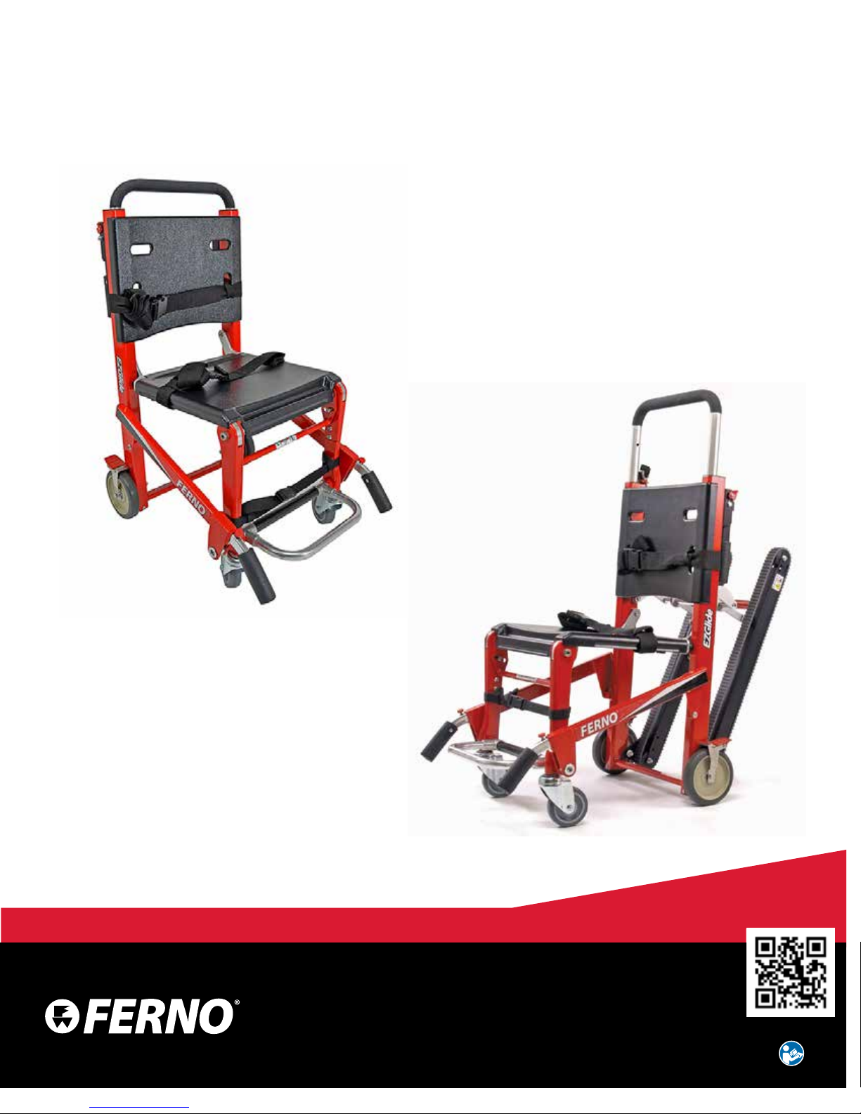
EZ-Glide
®
Evacuation Chair
Models 59, 59T, 59T-LWH
Users’ Manual
July 2018
Pub. No. 234-3298-07
Read this Manual and Retain
for Future Reference
Page 2
Ferno Customer Relations
For ordering assistance or general information:
CANADA AND THE U.S.A.
Telephone (Toll-free) 1.877.733.0911
Telephone 1.937.382.1451
Fax (Toll-free) 1.888.388.1349
Fax 1.937.382.1191
Internet www.ferno.com
ALL OTHER LOCATIONS
For assistance or information, please contact your Ferno distributor. If
you do not have a Ferno distributor, please contact Ferno Customer
Relations:
Ferno-Washington, Inc., 70 Weil Way
Wilmington, Ohio 45177-9371, U.S.A.
Telephone Country Code +1.937.382.1451
Fax Country Code +1.937.382.6569
Internet www.ferno.com
USERS’ MANUALS
To request additional free users’ manuals,
contact Ferno Customer Relations, your Ferno
distributor, or www.ferno.com.
Disclaimer
This manual contains general instructions for the use, operation
and care of this product. The instructions are not all-inclusive. Safe
and proper use of this product is solely at the discretion of the user.
Safety information is included as a service to the user. All other safety
measures taken by the user should be within and under consideration
of applicable regulations and local protocol. Training on the proper use
of this product must be provided before using this product in an actual
situation.
Retain this manual for future reference. Include it with the product in
the event of transfer to new users. Additional free copies are available
upon request from Customer Relations.
Proprietary Notice
The information disclosed in this manual is the property of FernoWashington, Inc., Wilmington, Ohio, USA. Ferno-Washington, Inc.
reserves all intellectual property rights, proprietary design rights,
manufacturing rights, reproduction use rights, and sales use rights
thereto, and to any article disclosed therein except to the extent those
rights are expressly granted to others or where not applicable to vendor
proprietary parts.
Limited Warranty Statement
The products sold by Ferno are covered by a limited warranty, which
is printed on all Ferno invoices. The complete terms and conditions of
the limited warranty, and the limitations of liability and disclaimers,
are also available upon request by calling Ferno at 1.800.733.3766 or
1.937.382.1451.
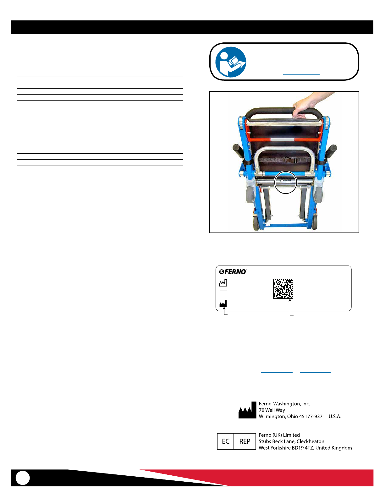
Serial Number _________________________
Location: Seat panel rear frame
Product Name/Model
Date of Manufacture
SN
Serial Number
Ferno-Washington Inc. | Wilmington, Ohio 45177 USA | +1.937.382.1451
Manufacturer
(01) Global Trade Item Number
(11) Date of Manufacture
(21) Serial Number
GS1 Data Matrix
UNIQUE DEVICE IDENTIFICATION SYSTEM
Ferno complies with the United States Food and Drug Administration’s
(FDA) Unique Device Identication (UDI) regulation to identify medical
devices. The UDI label contains information in human- and machinereadable form. Device information is online at the FDA’s Global Unique
Device Identication Database (GUDID). The public can search and
download information at AccessGUDID at www.fda.gov.
The label is located either on the product or the product packaging.
1.937.382.1451
44 (0) 1274 851999
2
© Ferno-Washington, Inc. / 234-3298-07 / July 2018
Page 3

TABLE OF CONTENTS
Section Page Section Page
Ferno Customer Relations ________________________________ 2
1 - Safety Information _____________________________________ 4
1.1 Warning __________________________________________ 4
1.2 Important ________________________________________ 4
1.3 Tip ______________________________________________ 4
1.4 Bloodborne Disease Notice __________________________ 4
1.5 Symbol Glossary ___________________________________ 5
1.6 Safety and Instruction Labels: Model 59 ________________ 6
1.7 Safety and Instruction Labels: Model 59T, Model 59T-LWH _ 6
2 - Operator Focus ________________________________________ 7
2.1 Operator Training __________________________________ 7
2.2 Terms ____________________________________________ 7
2.3 Using Additional Help_______________________________ 8
3 - About the Chair ________________________________________ 9
3.1 Description _______________________________________ 9
3.2 General Specications ______________________________ 9
3.3 Components: Model 59 ____________________________ 10
3.4 Components: Model 59T, Model 59T-LWH _____________ 11
4 - Setup ________________________________________________ 12
4.1 Attaching Patient Restraints _________________________ 12
4.2 Restraint Congurations ____________________________ 12
4.3 Ankle Restraint ___________________________________ 13
5 - Features _____________________________________________ 14
5.1 Folding and Unfolding the Chair _____________________ 14
5.2 Track System (Models 59T, 59T-LWH Only) _____________ 15
5.3 Extending Lift Bar _________________________________ 16
5.4 Telescoping Lift Handles____________________________ 16
5.5 Footrest _________________________________________ 17
5.6 Wheel Locks _____________________________________ 17
5.7 Rear Lift Handles Model 59T-LWH Only ________________ 18
5.8 Rear Lift Handles Models 59, 59T (Optional) ____________ 19
6 - Using the Chair _______________________________________ 20
6.1 Before Placing the Chair in Service ___________________ 20
6.2 General Guidelines for Use __________________________ 20
6.3 Transferring the Patient ____________________________ 21
6.4 Rolling the Chair __________________________________ 21
6.5 Transporting a Patient Down Stairs (Model 59) __________ 22
6.6 Transporting a Patient Down Stairs
(Models 59T, 59T-LWH) _____________________________ 23
6.6 Transporting a Patient Up Stairs (All Models) ___________ 25
6.7 Pausing On the Stairs ______________________________ 26
7 - Maintenance _________________________________________ 27
7.1 Maintenance Schedule _____________________________ 27
7.2 Disinfecting/Cleaning Restraints _____________________ 27
7.3 Disinfecting/Cleaning the Chair ______________________ 27
7.4 Cleaning Tracks and Belts ___________________________ 27
7.5 Inspecting the Chair _______________________________ 28
7.6 Lubricating the Chair ______________________________ 29
7.7 Do Not Lubricate Track System ______________________ 29
7.8 Reconditioning the Track Belts _______________________ 30
7.9 Adjusting Track-Belt Tension ________________________ 31
7.10 Removing and Attaching the ABS Panels ______________ 33
8 - Accessories ___________________________________________ 34
9 - Parts and Service ______________________________________ 35
9.1 U.S.A. and Canada _________________________________ 35
9.2 Worldwide _______________________________________ 35
9.3 Parts List ________________________________________ 35
9.4 Parts Diagrams ___________________________________ 36
Training Record__________________________________________ 37
Maintenance Record _____________________________________ 38
Notes __________________________________________________ 39
© Ferno-Washington, Inc. / 234-3298-07 / July 2018
3
Page 4
Safety Information
1 SAFETY INFORMATION
1.1 Warning
Warning notices indicate a potentially hazardous situation which, if not
avoided, could result in injury or death.
WARNING
Untrained operators can cause injury or be injured.
Permit only trained personnel to operate the chair.
Improper use of the chair can cause injury. Use the chair
only for the purpose described in this manual.
Improperly attaching restraints can allow seat and back
panels to dislodge, resulting in injury. Restraints must
capture panel AND chair frame.
Using the chair with the track system unlocked can cause
injury. Verify that the track system is locked before
transporting the patient.
Lubricating the track system can result in injury to the
patient and/or operators. Never lubricate the tracks or belts.
Improper operation can cause injury. Operate the chair
only as described in this manual.
An unattended patient can be injured. Stay with the
patient at all times.
An unrestrained patient can fall o the chair and be
injured. Use restraints to secure the patient on the chair.
Helpers can cause injury or be injured. Maintain control
of the chair, operate the controls, and direct all helpers.
Improper maintenance can cause injury. Maintain the
chair only as described in this manual.
Attaching improper items to the chair can cause injury.
Use only Ferno-approved items on the chair.
Improper parts and service can cause injury. Use only
Ferno parts and Ferno-approved service on the chair.
Modifying the chair can cause injury and damage. Use the
chair only as designed by Ferno.
1.2 Notice
Notices emphasize important, but not hazard-related information.
Failure to follow Notices could result in product or property damage.
NOTICE
1.3 Tip
Tips provide recommendations for easier use of the product.
1.4 Bloodborne Disease Notice
To reduce the risk of exposure to bloodborne diseases such as HIV-1
and hepatitis when using the chair, follow the disinfecting and cleaning
instructions in this manual.
4
© Ferno-Washington, Inc. / 234-3298-07 / July 2018
Page 5
Safety Information
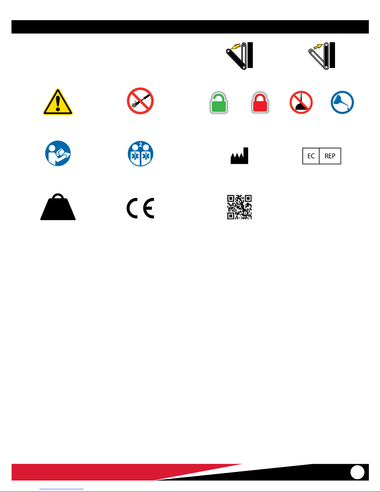
1.5 Symbol Glossary
The symbols dened on this page are used on the chair and/or in this
users’ manual. Ferno uses symbols recognized by the International
Standards Organization (ISO), American National Standards Institute
(ANSI) and the emergency medical services industry.
Open Track System Close Track System
General Warning of
Potential Injury
Read the Users’ Manual
500 lb
227 kg
35.7 st
Load Capacity
(Safe Working Load in
pounds, kilograms, stone)
Do Not Pressure Wash
Operation Requires
Two Trained Operators
Product meets
European Union Standards
Do Not
Lubricate
Manufacturer Authorized Representative in the
European Community
QR Code
(Access Online Content)
LubricateUnlocked Locked
© Ferno-Washington, Inc. / 234-3298-07 / July 2018
5
Page 6

Safety Information
1.6 Safety and Instruction Labels:
Model 59
Safety and instruction labels place important information from the
users’ manual on the chair. Read and follow label instructions. Replace
worn or damaged labels immediately.
Safe Use Guidelines
Instruction: Folding/Unfolding the Chair
Ferno Products are Protected by Patents Worldwide
Safety Instruction: Attaching Restraints
1.7 Safety and Instruction Labels:
Model 59T, Model 59T-LWH
Safety and instruction labels place important information from the
users’ manual on the chair. Read and follow label instructions. Replace
worn or damaged labels immediately.
Safe Use Guidelines
Instruction:
Adjusting Lift Bar
Instruction: Opening the Tracks
Instruction: Folding/Unfolding the Chair
Ferno Products are Protected by Patents Worldwide
Instruction:
Closing Tracks
Risk of Injury: Do Not
Lubricate Tracks
6
Safety Instruction: Attaching Restraints
© Ferno-Washington, Inc. / 234-3298-07 / July 2018
Page 7

Operator Focus
2 OPERATOR FOCUS
2.1 Operator Training
Operator using the chair:
● must read and understand this manual.
● must have training on proper use of the chair.
● must have a training on emergency-medical service and emergency
patient-handling procedures.
● must have the physical ability to assist the patient.
● must practice with the chair before using it with a patient.
● must keep training records. For a sample training record sheet, see
“Training Record” on page 37.
2.2 Terms
The following terms are used in this manual.
● INTERACTIVE CONTENT: For training videos and proper use of the
chair, scan a QR code in this manual, click a link in an electronic
version of this manual or visit our website at www.ferno.com.
● LOAD: The load is the overall weight of the patient plus equipment
placed on (or attached to) the chair.
● LOAD CAPACITY: Load capacity is the amount of weight the chair
is designed to hold. This includes the patient weight plus any
accessories attached to the chair (IV poles, bags, etc.)
● OPERATORS: Trained operators are referred to as Head-end Operator
and Foot-end Operator in this manual. Trained operators maintain
control of the chair, operate the controls, and direct helpers.
● SPOTTER: If available, Ferno recommends the use of a spotter
when moving the chair on stairs. The spotter stands behind the
backward-facing operator and helps steady and guide the operator.
WARNING
Untrained operators can cause injury or be injured.
Permit only trained personnel to operate the chair.
© Ferno-Washington, Inc. / 234-3298-07 / July 2018
7
Page 8
Using the Chair
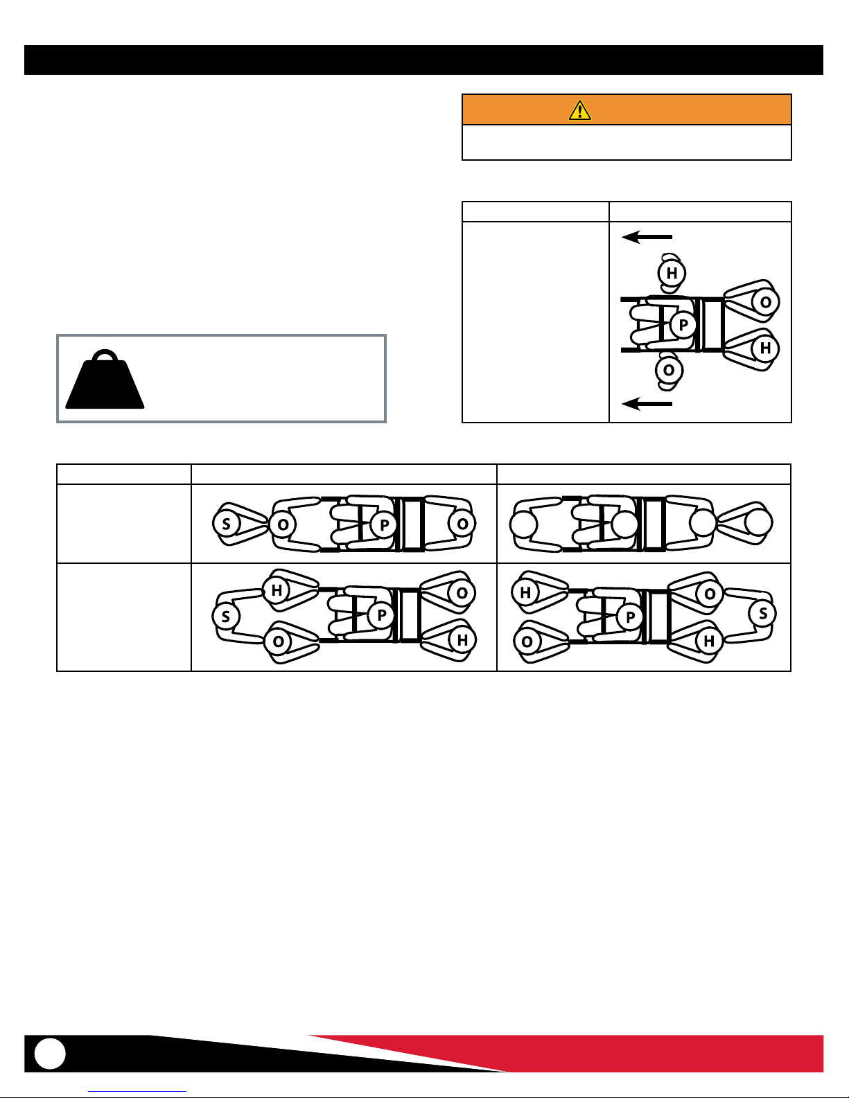
2.3 Using Additional Help
Operating the chair requires a minimum of two trained operators. Ferno
recommends:
● Position a trained operator at each end of the chair;
● Operators and helpers should face each other when transporting a
patient up or down stairs;
● A third trained person should serve as a spotter for the backward-
facing operator.
● Follow all applicable local protocols for carrying chairs.
Trained operators maintain control of the chair and operate the controls.
The designated lead operator should direct all helpers. The charts on
this page show suggested placement for operators and helpers.
500 lb
227 kg
35.7 st
Direction Descend Ascend
Inspect the chair if the Load Capacity has
been exceeded. See “Inspecting the Chair”
on page 28.
Load Capacity
WARNING
Helpers can cause injury. Maintain control of the chair,
operate the controls, and direct all helpers.
Direction Rolling on Flat Surface
Two Operators and
Two Helpers
Two Operators and
One Helper
Two Operators and
Three Helpers
O
Key: O = Operator H = Helper S = Spotter P = Patient
P
O
S
8
© Ferno-Washington, Inc. / 234-3298-07 / July 2018
Page 9
About the Chair
3 ABOUT THE CHAIR
3.1 Description
Note: In this manual, all chair models are referred to as “the chair” when
features or operation is identical. When a feature or operation diers, the
specic chair model name is used.
The chair is for professional use by a minimum of two trained operators.
A third person to serve as a spotter may be required by local protocols.
Additional help may be required when working with heavy patients.
The Ferno® Model 59 EZ-Glide® Evacuation Chair is an emergency
patient-handling device designed to transport a seated patient up and
down stairs and over at surfaces. The chair does not feature tracks.
Operators lift and carry the chair up or down stairs.
The Ferno® Model 59T or 59T-LWH EZ-Glide® Evacuation Chair are
emergency patient-handling devices designed to transport a seated
patient up and down stairs and over at surfaces. The chair is designed
with belted tracks that enable operators to “glide” the chair down stairs
instead of carrying it.
The dierence between models 59T and 59T-LWH is the weight of the
chair (see table at right), and the use of the rear lift handles. Rear lift
handles are available as an accessory to Model 59T. Model 59T-LWH
is constructed with two-stage, locking rear lift handles as standard
equipment.
POWERTraxx® conversion kits are available to provide a powered
track system for Models 59T or 59T-LWH. To purchase accessories, see
“Accessories” on page 34.
CHAIR FEATURES
● (59T, 59T-LWH) Belted track system for “gliding” chair down stairs
● Molded ABS seat and back panels
● Choice of color
● 5-position extending rear lift bar
● 5-position telescoping front lift handle (2)
● 6” rear locking wheel (2)
● 4” front swivel wheel (2)
● Folding footrest
● Ankle restraint
● Patient restraints (page 11)
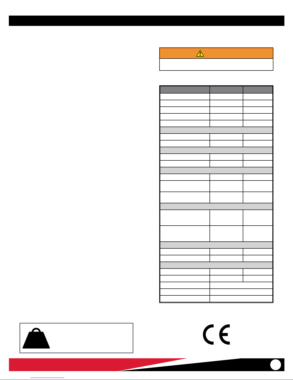
3.2 General Specications
Specications for the chair are shown in the table at right. General
specications are rounded. Metric conversions are calculated before
rounding the Imperial measurement.
Ferno reserves the right to change specications without notice. For
more information, contact Ferno. See “Ferno Customer Relations” on
page 2
WARNING
Improper use of the chair can cause injury. Use the chair
only for the purpose described in this manual.
Specication Imperial Metric
Load Capacity 500 lb 227 kg
Load Capacity (UK) --- 35.7 st
Weight* Model 59 26 lb 12 kg
Weight* Model 59T 37 lb 17 kg
Weight* Model 59T-LWH 40 lb 18 kg
Height
Maximum 63.5 1613 mm
Minimum 37.5 in 953 mm
Width
Overall 20.313 in 516 mm
Seat 16.5 in 419 mm
Depth (front to back)
Model 59 27 in 690 mm
59T, 59T-LWH Tracks closed,
Handles retracted
59T, 59T-LWH Tracks Open,
Handles extended
Folded
Model 59
Length x width x depth
59T, 59T-LWH
Length x width x depth
Wheels, Rear
Diameter 6 in 152 mm
Width 1.25 in 32 mm
Wheels, Front
Diameter 4 in 102 mm
Width 1.18 in 30 mm
Chair Construction Rectangular aluminum
Seat/Back Panels ABS Plastic
Wheel Bearings Sealed/greaseless
* Weight is without restraints or accessories
28.5 in 724 mm
51 in 1295 mm
37.5 in x
20.313 in x
9 in
37.5 in x
20.313 in x
10 in
953 mm x 516
mm x 225 mm
953 mm x 516
mm x 250 mm
500 lb
227 kg
35.7 st
© Ferno-Washington, Inc. / 234-3298-07 / July 2018
Inspect the chair if the Load Capacity has
been exceeded. See “Inspecting the Chair”
on page 28.
Load Capacity
9
Page 10
About the Chair
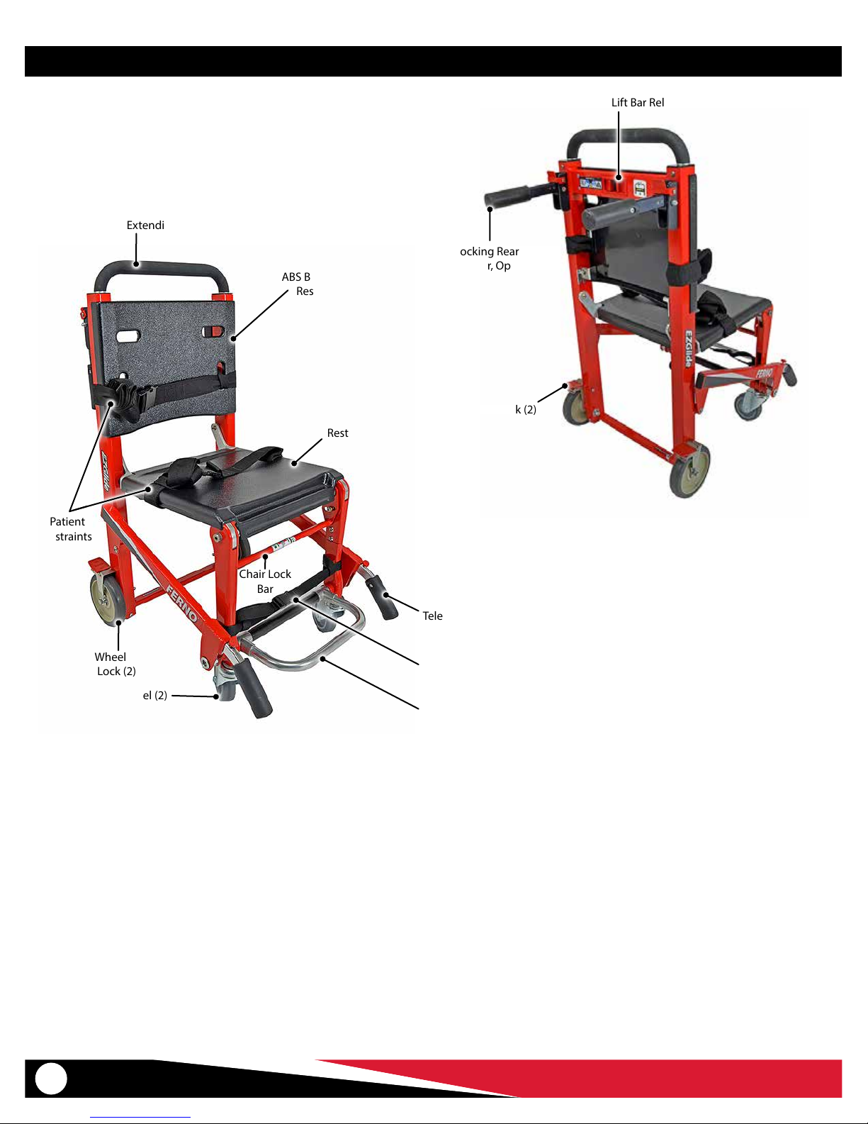
3.3 Components: Model 59
Extending Lift Bar
Removable
ABS Back Panel with
Restraint Slots
Removable
ABS Seat Panel with
Restraint Slots
Lift Bar Release
Locking Rear Handle
(Pair, Optional)
Wheel Lock (2)
Patient
Restraints
6" Wheel
with Lock (2)
4" Swivel Wheel (2)
Chair Lock
Bar
Telescoping Lift Handle (2)
Ankle Restraint
Folding Footrest
10
© Ferno-Washington, Inc. / 234-3298-07 / July 2018
Page 11
About the Chair
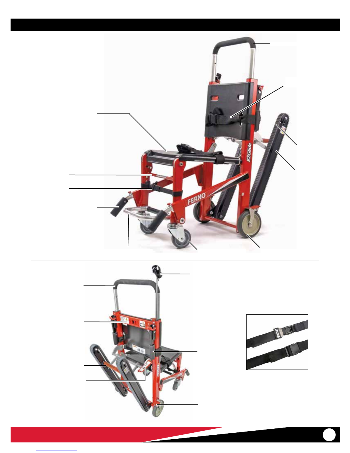
3.4 Components: Model 59T, Model 59T-LWH
Removable ABS Back Panel
with Restraint Slots
Removable ABS Seat Panel
with Restraint Slots
Chair Lock Bar
Ankle Restraint
Telescoping Lift Handle (2)
Extending Lift Bar
Patient
Restraint (2)
Belt (2)
Track (2)
Extending Lift Bar
Lift Bar Release Tabs
Track Release Bar
Track Closing Handle
4" Swivel Wheel (2) 6" Wheel with Lock (2)Folding Footrest
IV Pole (Optional)
Locking Rear
Handle
(Pair, Optional)
Wheel Lock (2)
Model 430
Model 430P
Restraint Options
(See “Accessories” on page 34)
© Ferno-Washington, Inc. / 234-3298-07 / July 2018
11
Page 12
Setup
4 SETUP
4.1 Attaching Patient Restraints
Use patient restraints to help hold the patient on the chair. Each
restraint must capture both the aluminum chair frame and the seat or
back panel. Follow local protocols when attaching restraints.
USING TWOPIECE RESTRAINTS
1. Feed a restraint strap loop through a slot in the seat or back panel.
2. Wrap the strap around the aluminum chair frame and feed the male
or female buckle through the loop, then pull the strap tight against
the frame and panel.
3. Repeat Steps 1-2 for the other half of the restraint.
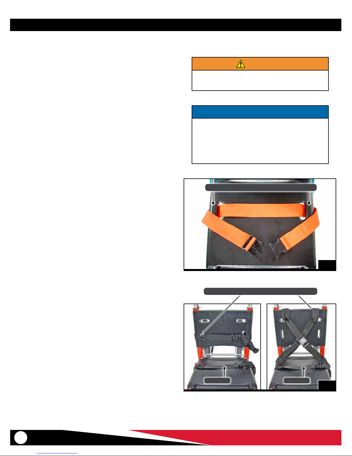
USING ONEPIECE RESTRAINTS
Note: Two-piece restraints are recommended.
1. To attach the seat-panel restraint, lay the restraint across the
top of the seat panel and feed the male and female ends of the
restraint down through the slots.
2. Wrap the restraint around the aluminum chair frame on each side
of the chair, capturing both the panel and the frame (Figure 1).
3. Buckle the restraint and adjust the length.
4. Repeat Steps 1-3 to attach the back-panel restraint.
WARNING
Improperly attaching restraints can allow seat and back
panels to dislodge, resulting in injury. Restraints must
capture panel AND chair frame.
NOTICE
Restraint rules (also follow your local protocols):
● Use a minimum of two restraints.
● One restraint must be secured across the chair seat to
help hold the patient on the chair.
● Each restraint or strap must capture the aluminum
chair frame and the plastic panel.
Capture Aluminum Frame and Panel at Each Side
4.2 Restraint Congurations
Follow local protocols when conguring and using restraints. Two
possible congurations are described below.
HORIZONTAL CONFIGURATION
Use one restraint for the chest and one restraint for the lap (Figure 2).
Use additional restraints as needed.
1. Attach the chest straps through vertical slots in the back panel.
2. Attach the lap straps through the seat panel slots.
CRISSCROSS CONFIGURATION
Use two restraints for the torso and a third restraint for the lap (Figure 2).
1. Attach one strap of a restraint through a horizontal slot on the
back panel of the chair.
2. Attach the mating strap of the same restraint through the seat
panel slot on the opposite side of the chair.
3. Repeat with the second restraint, attaching its straps to opposite
sides of the chair.
4. Attach the lap restraint through the seat-panel slots.
1
Straps Must Capture Aluminum Frame and Panels
Lap BeltLap Belt
2
12
© Ferno-Washington, Inc. / 234-3298-07 / July 2018
Page 13

Setup/Installation
4.3 Ankle Restraint
Use the ankle restraint to help keep the patient’s feet on the footrest.
Attach the two-piece ankle restraint to the front legs of the chair. To
attach the restraint:
1. Unbuckle the restraint to separate the straps.
2. Wrap a strap around one front leg of the chair and thread the
buckle through the loop, then pull the strap tight around the
chair leg (Figure 3).
3. Attach the remaining strap to the opposite front leg.
4. Buckle the restraint and adjust the length (Figure 4).
3
4
© Ferno-Washington, Inc. / 234-3298-07 / July 2018
13
Page 14

Features
5 FEATURES
5.1 Folding and Unfolding the Chair
The red lock bar below the front edge of the seat disengages the lock for
unfolding and folding the chair. Before seating a patient, verify that the
chair is completely unfolded and the lock is engaged.
FOLDING THE CHAIR
1. Buckle the restraints and arrange the straps to prevent interference
with folding the chair.
2. Roll the chair backward to reverse the swivel wheels (Figure 5).
3. Standing at the side of the chair, grasp the lift bar with one hand
and the lock bar with the other hand.
4. Pull the lock bar forward or toward the front of the chair (Figure 6),
then fold the seat toward the lift bar.
AS YOU FOLD THE SEAT: Tilt the chair forward (Figure 7) to keep
the swivel wheels rotated outward. This prevents the wheels from
holding the frame away from the seat and allows the lock to engage.
5. Press the seat against the back-panel frame until the lock engages
(Figure 8).
6. Verify the lock has engaged by pulling the seat away from the lift
bar without pulling the lock bar. The seat will not move if the lock
is engaged.
Note: If the swivel wheels prevent the chair from locking in the folded
position, hold the chair at a greater tilt to allow the swivel wheels to rotate
away from the chair frame.
Folding and Unfolding the Chair
The chair lock must be disengaged before you
begin folding or unfold the chair. Pull the lock
bar forward, then fold or unfold the chair.
When folding the chair, tilt the seat forward so
the swivel wheels rotate outward, away from
the seat.
Swivel Wheels
Reversed
5
Lock Bar
6
UNFOLDING THE CHAIR
1. Stand beside the chair and grasp the lift bar with one hand and
the lock bar with the other hand.
2. Pull the lock bar forward (toward the front of the chair), then pull
the seat away from the lift bar until the chair fully unfolds and the
lock engages.
3. To verify the lock has engaged, hold the lift bar while pulling up
on the chair frame at the front of the seat. The chair will not fold if
the lock is engaged.
7 8
14
© Ferno-Washington, Inc. / 234-3298-07 / July 2018
Page 15

Features
5.2 Track System
(Models 59T, 59T-LWH Only)
The track system enables operators to glide the chair down stairs
instead of lifting and carrying it.
GUIDELINES FOR USE
● Using the chair on stairs requires a minimum of two trained
operators. Ferno recommends using a third person as a “spotter”.
See “Transporting a Patient Down Stairs (Models 59T, 59T-LWH)”
on page 23.
● Verify that the track system is fully open and locked before use.
● Never lubricate the belts. Lubrication can cause the belts to perform
unpredictably, resulting in injury to the patient and/or operators.
● Moisture, water, snow, ice, or debris on or between the tracks and belts
can cause irregular belt performance that results in sudden changes in
the weight operators must support. Make sure the tracks and belts are
clean and dry before using the chair on stairs.
● Moisture, water, snow, ice, or debris on the stairs can cause poor
footing for operators. To avoid possible injury, clear the stairs or
select an alternate route.
OPENING THE TRACK SYSTEM
1. Grasp the red release bar (Figure 9) and rmly pull the track
system away from the chair until it locks in the open position.
2. Verify that track system has locked by trying to push the tracks
closed. If the lock is fully engaged, the track system will not close.
WARNING
Using the chair with the track system unlocked can
cause injury. Verify that the track system is locked before
transporting the patient.
Lubricating the track system can result in injury to patient
and/or operators. Never lubricate the tracks or belts.
9
CLOSING THE TRACK SYSTEM
With your hand, push the red closing handle down (Figure 10) until the
track system closes completely.
10
© Ferno-Washington, Inc. / 234-3298-07 / July 2018
15
Page 16

Features
5.3 Extending Lift Bar
The rear operator uses the lift bar to guide and steer the chair when
rolling the chair and to control the chair on stairs.
The lift bar adjusts to ve locked positions (Figure 11). Adjust the height
according to operator preference and the task or situation at hand.
RASING AND LOWERING THE LIFT BAR
1. Pinch and hold the release tabs together with one hand to unlock
the lift bar (Figure 12), then raise or lower the lift bar with the
other hand.
2. When the lift bar is near the desired position, let go of the release
tabs and raise or lower the lift bar until it locks into position.
3. Verify that the lift bar is locked by trying to raise or lower it without
squeezing the release tabs. When the lock is engaged the lift bar
will not move.
5.4 Telescoping Lift Handles
The telescoping lift handles adjust to ve locked positions (Figure 11).
Adjust the handles according to operator preference and the task at hand.
Lift Bar
5 Locking Positions
Lift Handle
5 Locking Positions
EXTENDING/RETRACTING THE LIFT HANDLES
1. Press the release button (Figure 13) and push or pull the handle
near the desired stopping point.
2. Release the button and slide the handle a little forward or
backward until it locks into position.
3. Lock both handles at the same position. Verify that both handles
are locked by trying to push or pull them without pressing the
release buttons. When the locks are engaged, the handles will not
move.
11
12
16
13
© Ferno-Washington, Inc. / 234-3298-07 / July 2018
Page 17

Features
5.5 Footrest
The footrest has two positions: raised for storage (Figure 14), and
lowered for use (Figure 15).
To lower the footrest, swing it down until it stops.
To raise the footrest, swing it up until it stops.
GUIDELINES FOR USING THE FOOTREST
Use the footrest properly to ensure that is does not interfere with
patient’s or operators’ feet.
● Before transferring the patient onto the chair, make sure the
footrest is raised in the storage position. Seat the patient before
lowering the footrest.
● When preparing to transfer the patient o the chair, unfasten the
ankle restraint and raise the footrest into the storage position
before unfastening the patient’s torso and lap restraints. This will
prevent the patient from attempting to stand before the footrest
has been stored out of the way of his/her feet.
● Keep the footrest raised when it is not in use.
14
Footrest
Raise the footrest to the storage position
before transferring the patient onto or o
from the chair.
5.6 Wheel Locks
The rear chair wheels are tted with wheel locks to help keep the chair
from rolling during patient transfer.
Stay with the chair and maintain control of it at all times. Do not use the
wheel locks as a substitute for operator control.
To engage a wheel lock, press down the rear end of the lock pedal
(Figure 16).
To disengage a wheel lock, press down the forward end of the lock
pedal.
15
© Ferno-Washington, Inc. / 234-3298-07 / July 2018
16
17
Page 18

Features
5.7 Rear Lift Handles
Model 59T-LWH Only
The Model 59T-LWH chair is constructed with two-stage locking handles
axed to the sides of the chair frame. Use the handles only as a pair. Do
not lift the chair using only one handle.
To raise the handles for use: Raise each handle until it locks with an
audible click.
To unlock and fold the handles:
To unlock and fold the handles, both locks must be disengaged.
1. Press and hold the red release lever to disengage the safety lock
(Figure 17).
2. With the red release lever still pressed, grasp the center of the
handle and lift the entire handle upward to unlock the secondary
lock (Figure 18). Keep the handle parallel with the oor as you
raise it.
3. Fold the handle and release the red release lever (Figure 19).
NOTICE
LIFT ONLY: Lift handles are designed for lifting and carrying
the chair only. Use the handles to lift and carry the chair up
stairs or over obstacles.
To tilt and roll the chair, use the lift bar. Do not press down on
the locked handles in order to tilt or turn the chair.
17
18
18
19
© Ferno-Washington, Inc. / 234-3298-07 / July 2018
Page 19

Features
5.8 Rear Lift Handles
Models 59, 59T (Optional)
If the Model 59T chair was purchased with the optional locking rear
lift handles, or if you installed a kit, use the handles as follows. To order
handles, see “Accessories” on page 34.
● Use the handles only as a pair. Do not lift the chair using only one
handle.
● To raise a handle, lift the handle until it locks with an audible click.
● To lower a handle, press the red release lever toward the chair to
disengage the lock (Figure 20), then lower the handle.
● Keep the handles folded when not in use.
NOTICE
LIFT ONLY: Lift handles are designed for lifting and carrying
the chair only. Use the handles to lift and carry the chair up
stairs or over obstacles.
To tilt and roll the chair, use the lift bar. Do not press down on
the locked handles in order to tilt or turn the chair.
20
© Ferno-Washington, Inc. / 234-3298-07 / July 2018
19
Page 20

Using the Chair
6 USING THE CHAIR
6.1 Before Placing the Chair
in Service
Personnel who will work with the chair need to read this manual.
● Set up the chair, following the instructions in this manual. See
“Setup” on page 12.
● Conrm that the chair operates properly. See “Inspecting the Chair”
on page 28.
6.2 General Guidelines for Use
● Medical advice is beyond the parameters of this manual.
● It is the users’ responsibility to ensure safe practices for the patient
and themselves.
● A minimum of two trained operators is required.
● Operators work together and maintain control of the chair at
all times.
● Follow standard emergency patient-handling procedures when
operating the chair.
● Operators communicate with one another and use coordinated
movements to operate the chair.
● Ferno recommends that a third trained person serve as a “spotter”
while using the chair on stairs.
● Lift only the weight you can safely handle. Use additional help
when working with heavy loads (patient and equipment). For
placement of help, see “Using Additional Help” on page 8.
● Stay with the patient at all times.
● Always use patient restraints to secure the patient on the chair.
● Remove any water, ice, snow, or debris from the stairs before using
the chair on them.
● Remove any water, ice, snow, or debris from the track and tread
belts before using the chair on stairs.
● Verify that the track system is locked in the open position before
using the chair on stairs.
WARNING
Helpers Improper operation can cause injury. Operate the
chair only as described in this manual.
An unattended patient can be injured. Stay with the
patient at all times.
An unrestrained patient can fall o the chair and be
injured. Use restraints to secure the patient on the chair.
Lubricating the track system can result in injury to patient
and/or operators. Never lubricate the track or belts.
NOTICE
LIFT ONLY: Lift handles are designed for lifting and carrying
the chair only. Use the handles to lift and carry the chair up
stairs or over obstacles.
To tilt and roll the chair, use the lift bar. Do not press down on
the locked handles in order to tilt or turn the chair.
20
© Ferno-Washington, Inc. / 234-3298-07 / July 2018
Page 21

Using the Chair
6.3 Transferring the Patient
Always assist the patient onto and o from the chair.
ASSISTING THE PATIENT ONTO THE CHAIR
1. Unfold the chair and verify that it is locked.
2. Engage the wheel locks.
3. Verify that the footrest is in the storage position.
4. Assist the patient onto the chair using accepted practices and
following local protocols.
5. Fasten and adjust the torso and lap restraints.
6. Lower the footrest and place the patient’s feet on it.
7. Fasten and adjust the ankle restraint (Figure 21).
ASSISTING THE PATIENT OFF FROM THE CHAIR
1. Engage the wheel locks.
2. Unfasten the ankle restraint and raise the footrest to the storage
position.
3. Unfasten the torso and lap restraints.
4. Assist the patient o from the chair using accepted practices and
following local protocols.
21
NOTICE
To tilt and roll the chair, use the lift bar. Do not use the rear lift
handle (if present).
6.4 Rolling the Chair
GENERAL GUIDELINES
● Roll the chair on smooth, at surfaces whenever possible (Figure 22).
● For patient comfort, pull the chair backward over low obstacles
such as door sills.
● Model 59: Use the extending lift bar (or accessory rear lift handles)
and telescoping foot-end handles to lift and carry the chair over
curbs, high and low obstacles, and rough terrain.
● Models 59T, 59T-LWH: Close the track system and use the
extending lift bar and telescoping foot-end handles to lift and
carry the chair over curbs, high obstacles, and rough terrain. Use
the track system to glide the chair down over curbs or single steps
(Figure 23).
TO ROLL THE CHAIR
1. Head-End Operator: Release the wheel locks.
2. Head-End Operator: Adjust the lift bar to a comfortable height
and grasp it to push and guide the chair on all four wheels (Figure
18), or tilt the chair back and roll it on its rear wheels.
3. Foot-End Operator: Assist the head-end operator as needed and
attend the patient.
22
23
© Ferno-Washington, Inc. / 234-3298-07 / July 2018
21
Page 22

Using the Chair
6.5 Transporting a Patient Down Stairs
(Model 59)
GENERAL GUIDELINES
● Carrying the chair down stairs requires a minimum of two
operators. Use additional help as needed. See “Using Additional
Help” on page 8.
● Ferno recommends that the two operators face each other when
transporting a patient down stairs and that a third person “spot” for
the foot-end operator (Figure 24). However, the foot-end operator
may face forward (with back to patient) if desired. Follow your local
protocols for carrying chairs.
● Remove any water, ice, snow, or debris from the stairs before using
the chair on them.
● Remove any water, ice, snow, or debris from the track system and
belts before using the chair on stairs.
● If the operators tire or need to attend the patient while on stairs,
see “Pausing On the Stairs” on page 26.
CARRYING THE CHAIR DOWN STAIRS
1. Head-End Operator: Roll the chair to the stairs and engage the
wheel locks.
2. Foot-End Operator: Extend the foot-end lift handles to the
desired stop point. Verify that both handles are locked and
maintain your grasp.
3. Spotter: Stand below the foot-end operator with a hand on the
operator’s back to help steady and guide him/her throughout the
descent (Figure 24).
4. Head-End Operator: Raise the lift bar to the desired position and
verify that it is locked. Or, use the rear lift handles, if your chair has
rear lift handles.
5. Head-End Operator: Disengage the wheel locks and tilt the chair
back.
6. Operators and Spotter: Operators work together to lift the chair
and carry it down the stairs. The spotter keeps a hand on the footend operator’s back and provides verbal guidance (Figure 24).
7. Operators: At the bottom of the stairs, the operators set the chair
on the oor and retract the lift handles.
8. Head-End Operator: Adjust the lift bar to a comfortable height
before rolling the chair.
Spotter
24
Pausing On the Stairs
To pause during the descent, allow the rear
wheels of the chair to rest on a step while both
operators hold the chair in place. See “Pausing
On the Stairs” on page 26. To continue down
the stairs, tilt the chair back and lift and carry it.
22
The Landing Zone
Ferno recommends you visualize a “landing
zone” of at the top or bottom of the stairway.
The landing zone should provide enough
clear, safe space for the chair to be set on
all four wheels, away from the edge of the
stairway.
© Ferno-Washington, Inc. / 234-3298-07 / July 2018
Page 23

Using the Chair
6.6 Transporting a Patient Down Stairs
(Models 59T, 59T-LWH)
GENERAL GUIDELINES
● Using the chair to move down stairs requires a minimum of two
trained operators working together. Use additional help as needed
to control the chair. See “Using Additional Help” on page 8.
● Ferno recommends that the two operators face each other when
transporting a patient on stairs and that a third trained person
“spot” for the foot-end operator (Figure 25). In some cases, the footend operator may be able to descend the stairs facing forward, with
his back to the patient. Follow your local protocols for using chairs.
● Remove any water, ice, snow, or debris from the stairs before using
the chair on them.
● Remove any water, ice, snow, or debris from the track system and
belts before using the chair on stairs.
● Verify that the track system is locked in the open position before
using the chair on stairs.
● If the operators tire or need to attend the patient while on stairs,
see “Pausing On the Stairs” on page 26.
GLIDING THE CHAIR DOWN STAIRS
1. Head-end Operator: Roll the chair near the stairs and engage the
wheel locks.
2. Head-end Operator: Open the track system (See “Track System”
on page 15). Verify that it has locked.
3. Head-End Operator: Raise the lift bar to the desired position and
verify that it is locked (Figure 25). Or, use the rear lift handles, if
your chair has rear lift handles.
4. Foot-end Operator: Extend the foot-end lift handles to the
desired positions and verify that all handles are locked (Figure 25).
5. Spotter: Stand below the foot-end operator with a hand on the
operator’s back to help steady and guide him/her throughout the
descent (Figure 25).
WARNING
Using the chair with the track system unlocked can
cause injury. Verify that the track system is locked before
transporting the patient.
Spotter
25
Pausing On the Stairs
To pause during the descent, allow the rear
wheels of the chair to rest on a step while both
operators hold the chair in place. See “Pausing
On the Stairs” on page 26. To continue down
the stairs, tilt the chair back and lift and carry it.
© Ferno-Washington, Inc. / 234-3298-07 / July 2018
The Landing Zone
Ferno recommends you visualize a “landing
zone” of at the top or bottom of the stairway.
The landing zone should provide enough
clear, safe space for the chair to be set on
all four wheels, away from the edge of the
stairway.
23
Page 24

Using the Chair
6. Head-end Operator: Disengage the wheel locks.
7. Both Operators: Together, tilt the chair back until the belts
engage the oor (Figure 26).
8. Both Operators: Working together, guide the chair slowly
forward and downward until the tracks engage two or three
steps. This establishes the glide angle (Figure 27).
9. Both Operators: To maintain the glide angle as you descend,
work together and:
○ Head-end Operator: Apply slight downward pressure on the
extended lift bar.
○ Foot-end Operator: Apply slight upward pressure on the foot-
end lift handles.
10. Both Operators: At the bottom of the stairway, tilt the chair onto
all four wheels.
11. If the chair has reached the destination, prepare the chair for rolling
by retracting the lift handles, rear lift handles, and/or lowering the
lift bar to a comfortable height (Figure 28). Close the track system.
12. To continue the descent, adjust the lift handles and lift bar as
needed to maneuver the chair to the next stairway.
Note: In a narrow stairway, you may need to retract the handles between
each ight of stairs.
26
24
27
28
© Ferno-Washington, Inc. / 234-3298-07 / July 2018
Page 25

Using the Chair
6.6 Transporting a Patient Up Stairs
(All Models)
GENERAL GUIDELINES
● Carrying the chair up stairs requires a minimum of two operators.
Use additional help as needed. See “Using Additional Help” on
page 8.
● Ferno recommends that the two operators face each other when
transporting a patient up stairs and that a third person “spot” for the
head-end operator. Follow your local protocols for carrying chairs.
● If the operators tire or need to attend the patient while on stairs,
see “Pausing On the Stairs” on page 26.
CARRYING THE CHAIR UP STAIRS
Note: If the chair is equipped with optional rear lift handles, the head-end
operator may grasp those handles instead of the lift bar. Model 59T-LWH is
shipped with rear lift handles as standard equipment.
1. Both Operators: Roll the chair to the bottom of the stairs and
position it with the patient’s back to the stairs.
2. Head-End Operator: Raise the lift bar to the desired position and
verify that it is locked. Or, use the rear lift handles, if your chair has
rear lift handles.
3. Head-End Operator: If the chair has a track system, do not open
the track system.
4. Spotter: Stand above the head-end operator with a hand on the
operator’s back to help steady and guide him/her throughout the
ascent (Figure 29).
5. Foot-End Operator: Extend the foot-end lift handles to the
desired position and verify that both handles are locked.
6. Both Operators and Spotter: Working together, the operators
grasp the lift bar and lift handles and carry the chair up the stairs.
The spotter keeps a hand on the head-end operator’s back and
provides verbal guidance (Figure 29).
7. Both Operators: At the top of the stairs, the head-end operator
sets the rear wheels of the chair on the oor and rolls the chair
backward until the front wheels are securely on the oor.
8. If the chair has reached the destination, prepare the chair for
rolling by retracting all handles and/or lowering the lift bar to a
comfortable height.
9. To continue the ascent, adjust the lift handles and lift bar as
needed to maneuver the chair to the next stairway.
Note: In a narrow stairway, you may need to retract the handles between
each ight of stairs.
Use Lift Bar or
Lift Handles
29
The Landing Zone
Ferno recommends you visualize a “landing
zone” of at the top or bottom of the stairway.
The landing zone should provide enough clear,
safe space for the chair to be set on all four
wheels, away from the edge of the stairway.
Tracked Chairs
The EZ-Glide track system is designed to assist
in descending stairs. To ascend stairs, lift and
carry the chair. When carrying the chair, close
the track system to keep it out of the way of the
head-end operator.
© Ferno-Washington, Inc. / 234-3298-07 / July 2018
25
Page 26

Using the Chair
6.7 Pausing On the Stairs
If the operators tire, or need to attend the patient during a transport up
or down stairs, the operators communicate and work together to pause
on the stairs (Figure 30).
PAUSING DURING A DESCENT
Both operators tilt the chair forward, o the tracks, to allow the rear
wheels to rest on the step. Both operators hold the chair in place.
To resume a descent, both operators tilt the chair back to the glide
angle and engage the belts on the steps. Then, continue down the stairs
as instructed in this manual. See “Transporting a Patient Down Stairs
(Model 59)” on page 22 or see “Transporting a Patient Down Stairs
(Models 59T, 59T-LWH)” on page 23.
PAUSING DURING AN ASCENT
Both operators set the chair down on its rear wheels on a step. Both
operators hold the chair in place (Figure 30).
To resume, lift and carry the chair as instructed in this manual. See
“Transporting a Patient Up Stairs (All Models)” on page 25.
30
26
© Ferno-Washington, Inc. / 234-3298-07 / July 2018
Page 27

Maintenance
7 MAINTENANCE
7.1 Maintenance Schedule
The chair requires regular maintenance. Set up and follow a
maintenance schedule. The table at right represents minimum intervals
for maintenance.
Keep maintenance records. A sample maintenance record sheet is
provided on page 38.
When using maintenance products, follow the manufacturers’ directions
and read the manufacturers’ material safety data sheets. You can purchase
a recommended disinfectant from your Ferno distributor or Ferno
Customer Relations (page 2).
7.2 Disinfecting/Cleaning Restraints
Ankle Restraint: Place buckled restraint in a mesh bag and launder in
a washing machine using warm water, a disinfectant soap, and gentle
agitation. Hang the restraint to dry. Do not put it in a dryer.
Chest and Lap Restraints: Disinfect and clean restraints as directed in
the restraint users’ manual provided. Additional, free users’ manuals can
be obtained from Ferno. See “Ferno Customer Relations” on page 2.
Minimum
Maintenance Intervals
Each Use
As Needed
Disinfect the Chair (this page)
Clean the Chair (this page)
Clean Tracks and Belts (this page)
Chair Inspection (page 28)
Track System Inspection (page 28)
Lubricating the Chair (page 29)
Adjust Belt Tension (page 31)
•
•
•
• •
• •
•
•
WARNING
Improper maintenance can cause injury. Maintain the
chair only as described in this manual.
Each Month
7.3 Disinfecting/Cleaning the Chair
To disinfect: Remove restraints and seat and back panels. Wipe all
surfaces of the chair and panels with disinfectant. Follow the disinfectant
manufacturer’s directions for application method and contact time.
To clean: Wash panels and all parts of the chair with warm water and
a mild detergent. Rinse with clean water. Dry with a towel or allow to
air-dry.
7.4 Cleaning Tracks and Belts
To ensure predictable belt performance, it is important to keep the track
and belts free of oil, grease, dirt, and debris.
1. Hold the belts away from the track frame and remove any debris.
2. Clean both sides of the track frame, and both belts, with SD-20™
All-Purpose Cleaner and a clean cloth. Follow instructions on the
container.
3. Dry track and belts thoroughly.
Note: To order SD-20™ Cleaner in North America, contact the Spartan
Chemical Company, Maumee, Ohio, USA at 1.800.537.8990 or visit
www.spartanchemical.com on the internet.
NOTICE
Disinfectants and cleaners containing bleach, phenolics, or
iodines can cause damage. Use caution when disinfecting
and cleaning with products containing these chemicals.
Using abrasive cleaning compounds or applicators on the
chair can cause damage. Do not use abrasive materials to
clean the chair or PowerTraxx.
DO NOT PRESSURE WASH
Water under high pressure, or steam, can
penetrate joints, ush away lubricant, and
cause corrosion. Do not pressure wash the
chair or PowerTraxx.
© Ferno-Washington, Inc. / 234-3298-07 / July 2018
27
Page 28

Maintenance
7.5 Inspecting the Chair
Have your service’s equipment maintenance personnel inspect the
chair at regular intervals. Conduct a visual inspection of the track system
before use, and a thorough inspection of the track system after each
use.
Follow the checklists on this page and work the chair through all its
functions as described in this manual.
If inspection shows damage or excessive wear, remove the chair from
service until repairs are made. See “Parts and Service” on page 35.
CHAIR INSPECTION
● Are all components present?
● Is the chair free of excessive wear?
● Are all screws, nuts, bolts, rivets, and roll pins securely
in place?
● Do all moving parts operate smoothly and properly?
● Do all locks on the chair operate properly?
● Does the chair roll smoothly?
● Are the restraints properly installed?
● Is restraint webbing in good condition with no cuts or
frayed edges?
● Are restraint buckles free of visible damage and do they
operate properly?
● Do installed accessories operate properly without
interfering with chair operation?
TRACK SYSTEM INSPECTION
● Are the tracks and belts free of lubricant, dirt and debris?
● Is there visible damage to the track or belts?
● Do the belts operate properly through the full range of
motion, without becoming loose or o-track?
● Are the inner cords of the belts visible (indicating the
need for replacement)?
● Are the belt-tensioning bolts and nuts tight?
28
© Ferno-Washington, Inc. / 234-3298-07 / July 2018
Page 29

Maintenance
7.6 Lubricating the Chair
Disinfect and clean the chair before applying lubricant.
There are two identical lubrication points on the chair. They are located
where the brass bushing in the chair lock bar slot meets the stainless
steel slide in the chair leg (Figure 31).
Lubricate each lubrication point with one drop of SAE 30-weight oil,
then move the lock bar back and forth a few times to work the oil into
the slide. Remove any excess lubricant with SD-20 Cleaner.
Note: To order SD-20™ Cleaner in North America, contact the Spartan
Chemical Company, Maumee, Ohio, USA at 1.800.537.8990 or visit
www.spartanchemical.com on the internet.
WARNING
Lubricating the track system can result in injury to patient
and/or operators. Never lubricate the tracks or belts.
NOTICE
Lubricating parts that should not be lubricated allows dirt
and foreign particles to collect on those parts, resulting in
damage. Lubricate only the reference points shown.
31
7.7 Do Not Lubricate Track System
Never lubricate the tracks, belts, or any other part of the track
system. Lubricants on the tracks or belts can cause the chair to perform
unpredictably, resulting in injury to the patient and/or operators.
A label (Figure 32) instructing the user not to lubricate the track system
is axed to each track. If these labels become damaged or worn, replace
them immediately. See “Parts and Service” on page 35.
If track or belts pick up oil or grease during use or while the chair is being
serviced, clean the track and belts with SD-20 All-Purpose Cleaner before
using the chair again. See “Cleaning Tracks and Belts” on page 27.
32
© Ferno-Washington, Inc. / 234-3298-07 / July 2018
29
Page 30

Maintenance
7.8 Reconditioning the Track Belts
Track belts need reconditioning when the inner surface becomes glassy
or glazed. As this glazing occurs, the belts begin to move less freely over
the steps and the belt teeth begin to skip, rather than roll, over the steps.
ITEMS REQUIRED FOR RECONDITIONING BELTS
1 ea Permanent marker
1 ea 50-80 grit sandpaper
1 ea Wood block
To recondition the belts:
1. Place the chair on a workbench.
2. Engage the wheel locks.
3. Roll the belt away from the track and mark the inner surface with
a permanent marker to identify the starting point for sanding
(Figure 33).
4. Wrap the wood block with sandpaper and place the sanding
block between belt and track. Move the block up and down to
sand the inner surface of the belt (Figure 34).
5. Rotate the track belt as needed to access additional surface to
sand.
Note: Take care and do not sand the surface of the track.
6. Repeat Steps 3-5 with the other belt.
7. Secure a simulated patient weight to the chair and glide the chair
down a ight of stairs to test whether the belts roll over the steps
properly.
8. If the belts do not perform properly, you may need to re-sand
them, or they may need to be replaced. See “Parts and Service”
on page 35.
33
30
34
© Ferno-Washington, Inc. / 234-3298-07 / July 2018
Page 31

Maintenance
7.9 Adjusting Track-Belt Tension
TOOLS NEEDED
2 ea 7/16-inch Wrench
1 ea #4 Phillips Screwdriver
1 ea Ruler or Measuring Tape
WHEN TO ADJUST BELT TENSION
Track belt tension needs to be adjusted when:
● a nut and bolt become loose
● a belt pulls away from the track more than 1-1/2 in. (38 mm) when
measured. Refer to “Method 1” on page 32.
● a belt pulls away from the track more than 1 in. (25 mm) when
measured. Refer to “Method 2” on page 32.
Adjusting Belt Tension
Adjusting the belt tension is a two-person
operation.
TENSIONADJUSTMENT
1. Decide if you will use Method 1 or Method 2 to measure and
adjust the track-belt tension.
2. For Method 1: Open the track system and lay the chair on its tracks
on a workbench (Figure 35).
For Method 2: Stand the chair on its wheels on a workbench,
then open the track system and engage both wheel locks.
3. Loosen the bolt and black cap locking nut located at the top end
of the track (Figure 36).
4. Slide the #4 Phillips screwdriver into the adjustment slot (Figure 36).
5. While one person tensions the belt by using the #4 Phillips
screwdriver to pull the belt roller toward the top of the track, the
other person uses the two 7/16-inch wrenches to tighten the bolt
and nut only enough to hold the tension (Figure 37).
#4 Phillips Screwdriver
in Adjustment Slot
Loosened Bolt
35
Loosened Black Cap
Locking Nut
(not visible in photo)
36
© Ferno-Washington, Inc. / 234-3298-07 / July 2018
37
31
Page 32

Maintenance
6. There are two methods for checking belt tension. You can use
whichever method you prefer, but do not use the chair position
from one method with the measurement range from the other
method.
Use Method 1 (below, left) if the chair is laying on its tracks on a
workbench. Use Method 2 (below, right) if the chair is standing
on its wheels.
Method 1
CHAIR MUST BE LAYING ON ITS TRACKS
ON A WORKBENCH
Grasp the belt at the track midpoint and pull the belt away
from the track to remove any slack, then measure the
distance between the exposed surface of the track and the
inner surface of the belt. Take the measurement at the track
midpoint.
The belt is correctly tensioned when the measurement from
the exposed surface of the track to the inner surface of the
belt is 1-1/4 in. to 1-1/2 in. (31.75 mm to 38 mm), as shown
(Figure 38).
7. It may be necessary to repeat the tensioning and measuring one
or more times to achieve the correct belt tension.
8. When the belt tension is correct, nish tightening the bolt and nut
to maintain the tension.
9. Repeat Steps 3-7 to adjust the tension of the other track belt.
Method 2
CHAIR MUST BE STANDING ON ITS WHEELS
Grasp the belt at the track midpoint and pull the belt away
from the track to remove any slack, then measure the
distance between the exposed surface of the track and the
inner surface of the belt. Take the measurement at the track
midpoint.
The belt is correctly tensioned when the measurement from
the exposed surface of the track to the inner surface of the
belt is 3/4 in. to 1 in. (19 mm to 25 mm) as shown (Figure 39).
32
38
39
© Ferno-Washington, Inc. / 234-3298-07 / July 2018
Page 33

Maintenance
7.10 Removing and Attaching
the ABS Panels
The molded ABS seat and back panels snap on and o the chair frame.
BACK PANEL
To remove the back panel: Gently pull downward on the ange near
one bottom corner and pull the corner of the panel away from the chair
(Figure 40). Repeat at the opposite corner. Then slide the panel up o
the two keepers at the top of the frame.
To attach the back panel: Orient the panel with the horizontal restraint
slots uppermost. Slide the two holes in the panel top ange down
over the keepers on the chair frame (Figure 41), then press both lower
corners of the panel against the sides of the frame until they snap into
place over the keepers.
SEAT PANEL
To remove the seat panel: Pull upward on the panel ange at each
front corner to pop the panel free of the seat frame (Figure 42) then lift
the panel o the chair.
To attach the seat panel: Align the panel with the chair frame and
press down to snap the panel onto the frame.
40
Panel Keeper (2)
41
42
© Ferno-Washington, Inc. / 234-3298-07 / July 2018
33
Page 34

Accessories
8 ACCESSORIES
Ferno oers a full line of emergency medical service accessories.
Selected items approved for use with the chair are listed here.
Always follow the instructions packed with accessories. Keep the
instructions with this manual. Be aware of any special considerations
(loading heights, door widths, etc.) when using accessories.
For product information, contact Ferno. See “Ferno Customer Relations” on
page 2
WARNING
Attaching improper items to the chair can cause injury. Use
only Ferno-approved items on the chair.
POWERTRAXX™ CONVERSION KITS
PowerTraxx™ conversion kits provide a powered track system for the
Model 59T series chair. Select the kit for your local electrical service.
Description Part #
120 VAC POWERTraxx® 083-2195
240 VAC POWERTraxx® 083-2196
EZGLIDE CHAIR ACCESSORIES
Description Part #
IV Bag Holder Complete 082-1976
IV Bag Holder Replacement Strap 082-1972
Headrest, Folding 083-2430
Head Strap Replacement 082-1970
EZ-Glide® Oxygen Cylinder Holder 082-1977
Oxygen Cylinder Replacement Straps 031-3661
Locking Rear Lift Handles (Pair, standard, for Model 59T) 082-1975
Locking Rear Lift Handles (Pair, for Model 59T-LWH) 082-7053
Vinyl Storage Cover 031-4023
WALL MOUNTS
Description Part #
Secure Mount Storage Brackets (with spring release) 082-2072
SecureLock+™ Storage Brackets (Suitable for use in an Ambulance) 60-0251-006
EZ-Glide Wall Bracket (Hook Secures Top of Chair Only) 082-2073
Metal Storage Cabinet 050-6534
RESTRAINTS
Model 59T Ankle Restraint 082-1973
Model 430 (Metal Buckle) Restraint
Style Black Orange
2 pc., 5’ (1524 mm) 031-3892 031-3891
2 pc., 7’ (2134 mm) 031-3911 031-3912
2 pc., 9’ (2743 mm) 031-3305 031-4013
Model 430P (Plastic Buckle) Restraint
Style Black Orange
2 pc., 5’ (1524 mm) 031-3797 031-3917
2 pc., 7’ (2134 mm) 031-3801 031-3919
34
© Ferno-Washington, Inc. / 234-3298-07 / July 2018
Page 35

Parts and Service
9 PARTS AND SERVICE
9.1 U.S.A. and Canada
In the United States and Canada, to order parts or for professional chair
repair, contact EMSAR® - the only agent authorized by Ferno to manage,
service, and repair Ferno products.
Telephone (Toll-Free) 1.800.73.EMSAR
Telephone 1.937.383.1052
Fax +1.937.383.1051
Internet www.EMSAR.com
9.2 Worldwide
To order Ferno parts, and for professional repair, contact your Ferno
distributor. Your distributor is the only agent authorized by Ferno to
manage, service, and repair Ferno products.
9.3 Parts List
Ref. # Description Part #
1 ABS backrest panel 190-1489
2 Track-close push handle 190-1500
3 ABS seat panel 190-1490
4 Seat bumper, pair w/hardware (n/v) 190-1501
5 Inner telescoping handle assy. (right-side or left-side) 090-5837
6 Telescoping handle, grip only 190-1495
7 4" Front caster, complete 190-1494
8 Rear brake assy, right 090-5841
9 6" Rear wheel w/hardware 190-1493
10 Ankle restraint 082-1973
11 Track lower roller w/hardware 190-1498
12 Rear brake assy, left (n/v) 090-5843
13 Track belt only 190-1496
14 Track upper roller w/hardware 190-1497
15 Lift bar lock assy 190-1492
16 Lift bar handle, complete 190-1491
17 Gas spring assy 190-1499
18 Label sheet and logo (n/s) 190-1502
19 Telescoping handle assembly See chart at right
20 Seat frame assembly (n/s) 090-5840
21 59T Track frame weldment 090-5842
22 59T Track release linkage 090-5844
(n/s) = not shown
WARNING
Improper parts and service can cause injury. Use only
Ferno parts and Ferno-approved service on the chair.
Modifying the chair can cause injury and damage. Use the
chair only as designed by Ferno.
Telescoping Handle Assemblies (complete)
Color Patient Side Part #
Red Left 190-1619
Red Right 190-1688
Orange Left 190-1687
Orange Right 190-1620
Green Left 190-1621
Green Right 190-1692
Platinum/Silver Left 190-1622
Platinum/Silver Right 190-1689
Blue Left 190-1618
Blue Right 190-1686
White Left 190-1691
White Right 190-1690
Note: Please specify the RIGHT-side or LEFT-side assembly and color when
ordering a telescoping handle assembly. “Right” or “Left” is as viewed by a
patient sitting on the chair.
© Ferno-Washington, Inc. / 234-3298-07 / July 2018
35
Page 36

9.4 Parts Diagrams
Parts and Service
14
13
12
15
21
16
22
10
1
2
3
4
6
5
Refer to
19
Chart On
7
Page 35
17
11
2018
8
9
Not Shown
36
© Ferno-Washington, Inc. / 234-3298-07 / July 2018
Page 37

Training Record
TRAINING RECORD
Date Printed Name Signature
Training Method
Read
Manual
Video/
Online
Hands-On
Trainer
Initials
© Ferno-Washington, Inc. / 234-3298-07 / July 2018
37
Page 38

Maintenance Record
MAINTENANCE RECORD
Date Maintenance Performed By
38
© Ferno-Washington, Inc. / 234-3298-07 / July 2018
Page 39

NOTES
© Ferno-Washington, Inc. / 234-3298-07 / July 2018
39
Page 40

© Ferno-Washington, Inc. / 234-3298-07 / July2018
 Loading...