

Ferno Arachnipod User Manual
1
Arachnipod User Manual
Version 6.0
© Copyright: FERNO AUSTRALIA
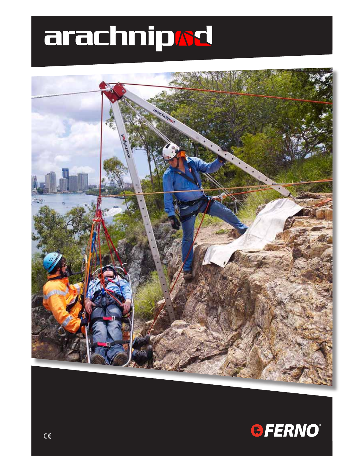
Total Edge Management System
USERS’ MANUAL
Version 6.1
CE Certied in 3 & 4 leg congurations to CEN/TS 16415:2013 for maximum 2 persons
and EN 795:2012 for single person use
Australia

Australia
2
Arachnipod User Manual Version 6.1
DOC ID: 00184-AU-V06 (2015/03)
CE Compliance Information 3
Introduction 4
WARNINGS 5
Working Load Limits (WLL) 6
Tripod and Kit Contents 7
General 9
Intended Purpose 9
Care, Maintenance & Storage 9
Transportation 10
Safety Information 10
Life Cycle 10
Non-metallic Components 10
Inspection of the Arachnipod 11
Repairs 11
Safe Working Practices 11
Principles of Edge Management 12
Critical Point Analysis 13
(High change of direction 13
The Two Rope System 14
Understanding the forces at a change of direction pulley 15
Understanding the forces being applied to the Arachnipod 15
Assessing the stability of your Arachnipod rigging 16
Tripod Stabilisation 16
Arachnipod Parts 17
Standard Leg 17
Pulley Leg 17
Pulley Leg 17
Reverse Head, Quad Plate and Quad Pod 18
Gin Head 18
Rigging Plate 18
Leg with a Standard Foot 19
Spike Foot & Soft Ground Shoe 19
Hold Down Stake 19
Bridge Beams and Trolley 20
Equipment Bracket 20
Steps 20
Bridge Systems 21
Arachnipod Assembly 22
Stabilisation 26
Anchoring the Arachnipod 26
Using an Arachnipod leg as an anchor 26
Tripod Stabilisation 27
Lazy Leg Tripod Stabilisation 28
Quadpod Stabilisation 29
A-Frame Stabilisation 30
Method 1 Standard A-frame 30
Method 2 Sideways A-frame (SA-frame) 30
Method 3 A-frame with a lazy leg 32
Gin Pole Stabilisation 33
Using a single leg to manage a handrail 34
Bridge Stabilisation 35
Accessories 36
Foot Options for your Arachnipod 36
Additional Accessories for your Arachnipod 37
Accessory Instructions
Winch 38
ISC UB171 Fall Arrest Adaptor Bracket
39
Lazy Leg Extension Kit 40
Lazy Leg Adaptor Plug 41
Equipment Bracket with 2:1 Rigging 42
Bridge Ratchet Strap Kit 43
Arachnipod Inspection 45
Arachnipod Disassembly 46
Leg Inspection 46
Inspecting the Heads of each leg 47
Standard Leg 47
Pulley Leg 47
Lazy Leg 48
Foot Inspection 48
Standard Feet 48
Spike Foot 48
Soft Ground Shoe 49
Hold Down Stake Inspection 49
Gin Head Inspection 49
Rigging Plate Inspection 50
Equipment Bracket Inspection 50
Reverse Head Inspection 50
Bridge Beam & Trolley Inspection 51
Arachnipod Winch Inspection 51
Forms
Arachnipod Kit Records 53
Regular & Annual Inspections 54
TABLE OF CONTENTS
3
Arachnipod User Manual
Version 6.0
© Copyright: FERNO AUSTRALIA
CE Compliance Information
CE Certifying Organisation
SAI Global NB2056
PO Box 5420, Sydney NSW 2001 Australia
Level 37, 680 George Street, Sydney NSW 2000 Australia
CE CEC40142A1 Certified in 3 & 4 leg configurations to CEN/TS 16415:2013 for maximum 2 persons and
EN 795:2012 for single person use
Ferno is represented throughout the European Union by:
Ferno (UK) Limited
Ferno House, Stubs Beck Lane,
Cleckheaton, West Yorkshire BD19 4TZ, United Kingdom
44 (0) 1274 851999
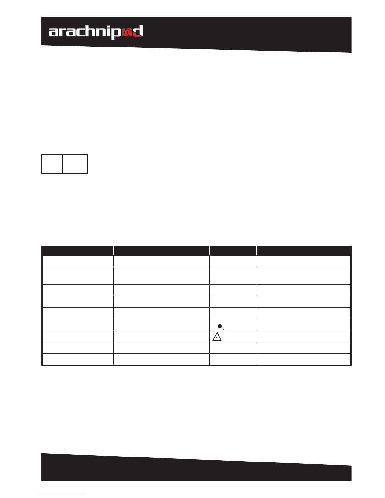
Glossary
Throughout this manual the following abbreviations are used:
Abbreviation Description Abbreviation Description
NB2056 No. of Notied body for PPE m Metre
CEN/TS 16415:2013
EN795:2012
Standard for anchor systems “ Inch
TEMS Total Edge Management System PPE Personal Protective Equipment
SA Sideways A-frame Qty Quantity
N/A Not applicable ea Each
kN Kilonewton
A
Anchor
kg Kilogram Load
lb Pound WLL Working Load Limit
mm Millimetre MBS Minimum Breaking strength
EC REP

Australia
4
Arachnipod User Manual Version 6.1
DOC ID: 00184-AU-V06 (2015/03)
Introduction
Congratulations on your purchase of the Arachnipod. The Arachnipod is a total edge management system that
will empower the end user with a wide range of conguration options.
The complete Arachnipod total edge management system (TEMS) can be rigged as a:
» Gin Pole (mono pole / monopod)
» A-frame (bipod)
» Sideways A-frame (SA-frame)
» Tripod
» Quadpod
» Lazy Leg or Easel Leg Tripod
» Handrail monopod (used to support to a handrail)
» Bridge
Components can be added or removed as required so that the Arachnipod compliments existing structural or
natural features making it the most versatile edge management solution on the planet.
Ferno knows that rigging is not always conducted on a at surface or with a clean edge so the Arachnipod was
designed with every conceivable task in mind. From the harshest vertical rescue conditions to a simple tripod for a
conned space entry task, the Arachnipod will provide the exibility that end users demand.
The versatility of the Arachnipod will appeal to a wide range of end users including rescuers, mines rescue,
industrial rope access workers, construction, and lm industries.
The end user can purchase as little or as much Arachnipod hardware to suit their scope of operations making the
Arachnipod an edge management system that is both aordable and upgradeable to suit changes in operational
needs.
With the appropriate training, the Arachnipod can be used in a variety of congurations and in any number of
environments from wilderness applications to industrial rope access scenarios.

5
Arachnipod User Manual
Version 6.0
© Copyright: FERNO AUSTRALIA
Activities conducted at height can be dangerous resulting in injury or death. Do not use this device unless you
have:
1. Read and understood the User’s Manual
2. Received appropriate training
3. Ensured a competent person has conducted a risk assessment for the specic task
4. Carried out a preoperational check of the Arachnipod, associated hardware and rigging before each use
5. Accepted total responsibility for your own safety, and
6. Proof tested drilled-in anchorages in accordance with local standards.
• This manual is not intended as a substitute for appropriate training. Training, practice and experience in
technical rigging are essential for safe use!
• The Arachnipod and associated hardware must always be secured to prevent it from falling over an edge.
The Arachnipod may become unstable if used without an assessment of the resultant force and direction.
Additional rigging may be required to ensure complete stabilisation.
• A primary rope or cable system with an independent safety back-up system must be used when loaded life
lines are rigged through any edge management device.
• The Arachnipod has been engineered and tested using the original equipment as supplied. Never replace any
pins, bolts or other components with non-genuine parts.
• Do not use your Arachnipod if any parts are missing.
• Arachnipods should be decommissioned from service after a maximum of 12 years from the date of
commissioning into service. However if the date of commissioning into service is NOT recorded, the unit
should be decommissioned from service after 12 years from the date of manufacture.
• For service or repairs, please contact your local Ferno Distributor or Ferno Australia
Tel: +61 7 3881 4999
Email: sales@ferno.com.au
www.ferno.com.au
WARNINGS
Australia
6
Arachnipod User Manual Version 6.1
DOC ID: 00184-AU-V06 (2015/03)
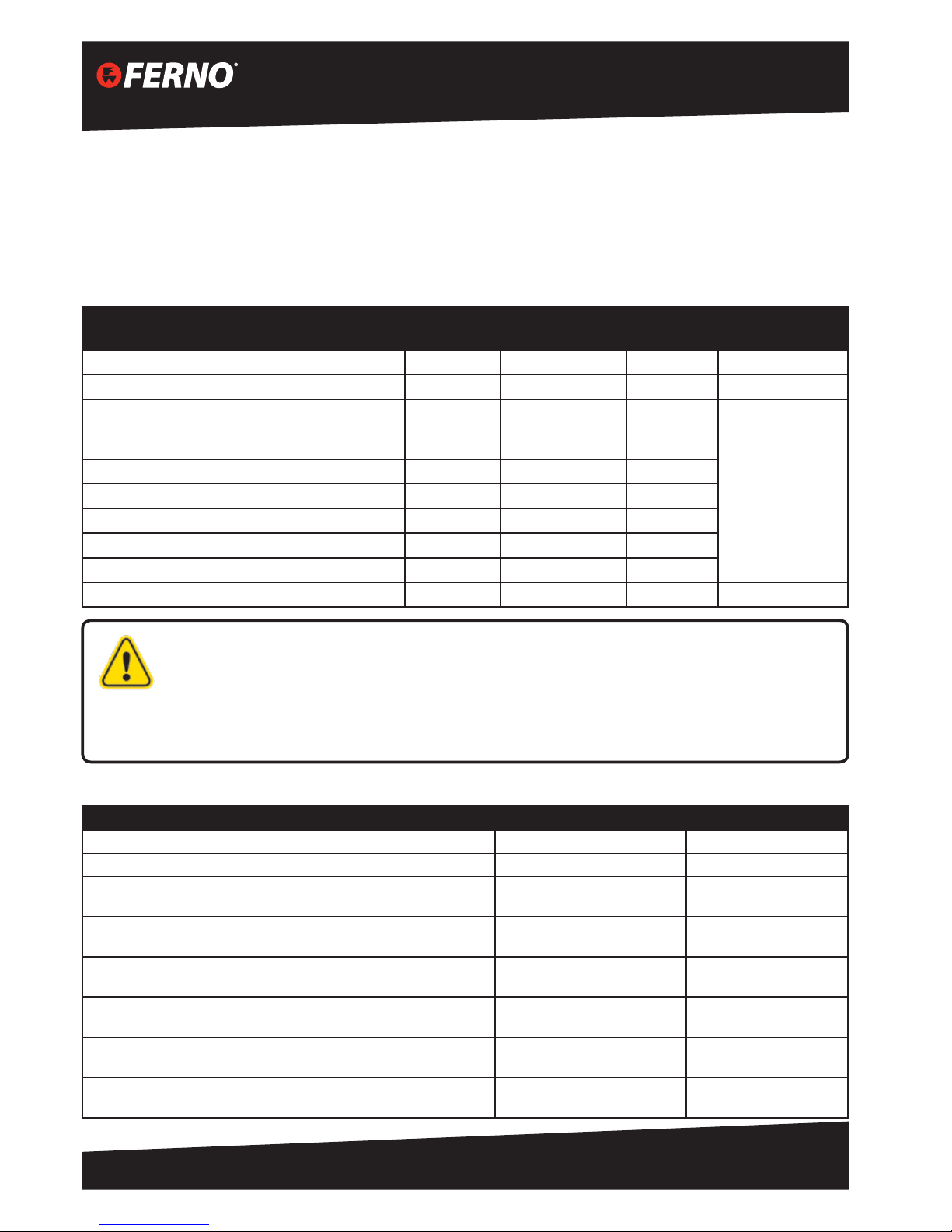
Working Load Limits (WLL)
The typical weight of a single person load ranges from 80 kg to 120 kg (176 lb* to 265 lb) depending upon a
number of factors. The WLL of the Arachnipod exceeds this load in all congurations.
The weight of a rescue load typically ranges from 200 kg to 280 kg (440 lb to 617 lb) depending upon a number
of factors. The Arachnipod oers many congurations that match or exceed the 280 kg load with only a few
exceptions. The table below outlines the working load limits of the Arachnipod in various congurations.
Leg Setting
WLL External
Anchor Point
MBS
WLL Load
Anchored to Leg
Gin Pole at 2050mm extension F-6 280kg/ 616lb 28kN N/A
Gin Pole at 3050mm full extension A-1 150kg/ 330lb 15kN N/A
A-Frame or
Offset A-Frame or
A-Frame with Lazy Leg
A-1
B-2
C-3
280kg/ 616lb
340kg/ 784lb
400kg/ 880lb
28kN
34kN
40kN
220kg/ 485lb
Tripod and Quadpod A-1 400kg/ 880lb 40kN
Handrail Monopole F-6 280kg/ 616lb 28kN
Bridge Beam 2000mm span* (middle of beam) A-1 280kg/ 616lb 28kN
Bridge Beam 3000mm span* (middle of beam) A-1 230kg/ 506lb 23kN
Bridge Beam 4000mm span* (middle of beam) A-1 175kg/ 385lb 28kN
Any span** (end of beam) A-1 280kg/ 616lb 19kN
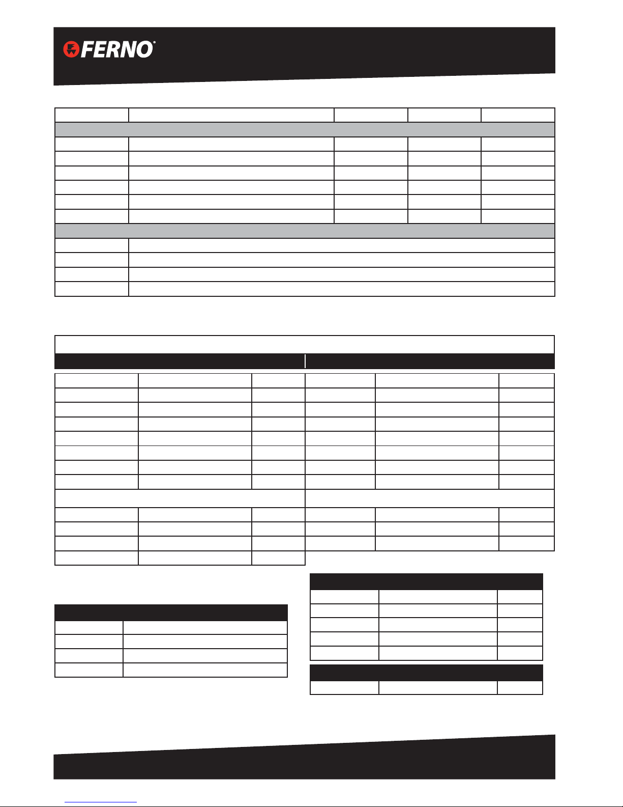
Dimensions and Weight
Item Storage Max Length Weight
Standard leg 1420 mm / 56” 3050 mm / 120” 8.6 kg / 19 lb
Pulley leg 1550 mm / 61” 3150 mm / 124” 10 kg / 22 lb
Tripod
370 mm x 130 mm x 1420 mm
14.6” x 5.1” x 56”
3050mm / 120” 25.8 kg / 57 lb
Tripod with pulley head
370 mm x 130 mm x 1550 mm
14.6” x 5.1” x 61”
3150mm / 124” 27.2 kg / 60 lb
Tripod bag (empty)
380 mm x 150 mm x 1600 mm
15” x 6” x 64”
N/A 6.5 kg / 14.3 lb
Accessory kit (full)
400 mm x 20 mm x 660 mm
15.7” x 7.9” x 26”
N/A 19 kg / 41.8 lb
2 m Bridge
290 mm x 150 mmx 2070 mm
11.5” x 6” x 81.5”
N/A 21 kg / 46.2 lb
2 m Bridge kit
300 mm x 160 mm x 2150 mm
11.8” x 6.3” x 84.7”
N/A 40 kg / 88 lb
* If bridge beam has Strongbac tted, WLL for bridge beam
becomes 280 kg / 616 lb at any length up to 6000 mm / 236”
* WLL for bridge trolley is 250 kg / 550 lb (ultimate strength 24.5kN)
* Throughout this manual 1 lb (pound) = 0.453 kg and 1 kg = 2.2 lb
**Bridge beam MBS diers depending on where the load is positioned along the beam. On a 2m bridge beam
the safety factors reduces from 10:1 to <7:1 as the trolley moves from the centre to the end of the beam.
7
Arachnipod User Manual
Version 6.0
© Copyright: FERNO AUSTRALIA
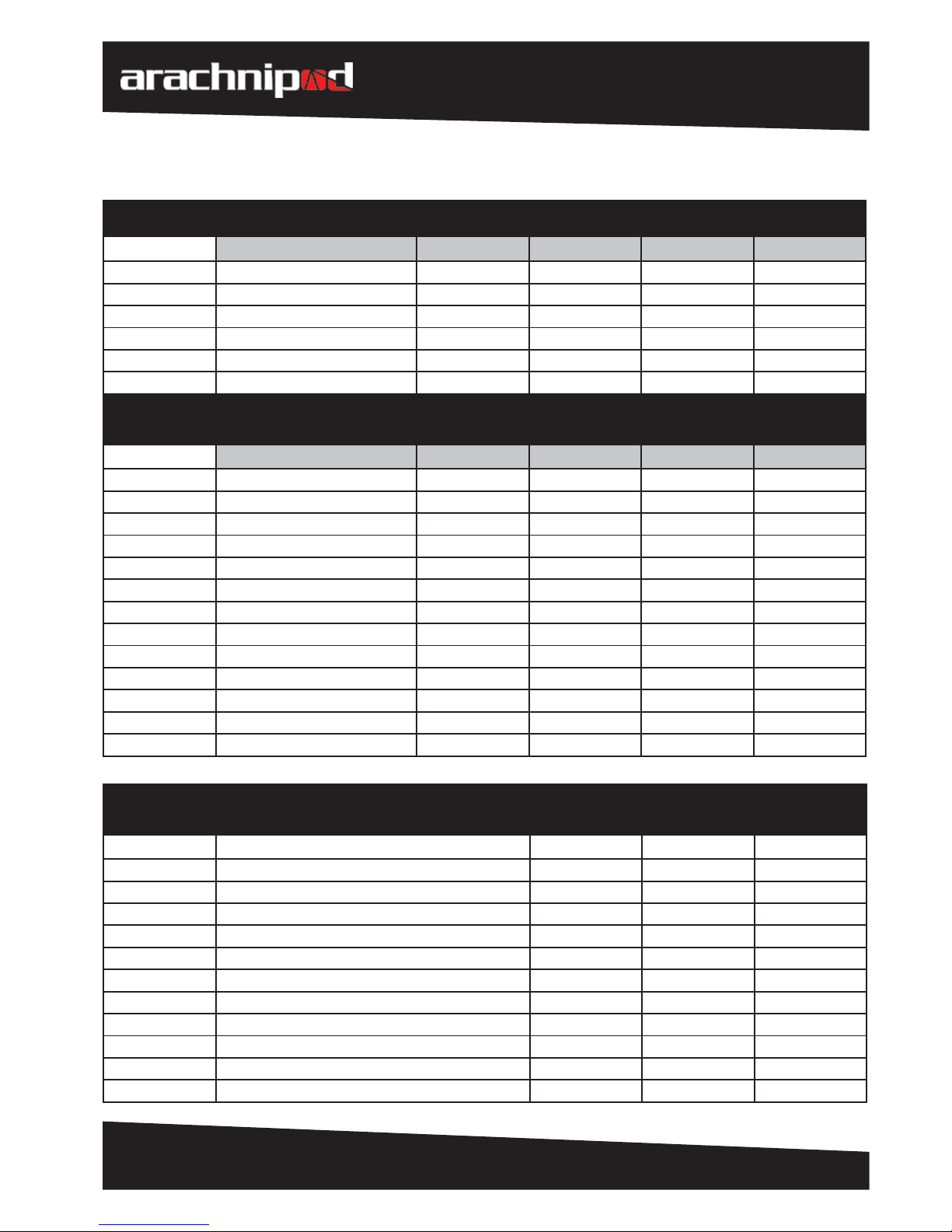
Tripod and Kit Contents
ARACHNIPOD
PART NUMBER
ARACHNIPOD
COMPONENT
ARACHNIPOD
INDUSTRIAL
ARACHNIPOD
INDUSTRIAL PLUS
ARACHNIPOD AD-
VANTAGE BASIC
ARACHNIPOD
ADVANTAGE
TRIPOD STYLES:
APOD-IND APOD-IND+ APOD-ADV-B APOD-ADV
90-0108 Standard Leg 3 2 2 1
90-0110 Pulley leg 1 1
90-0114 Lazy leg 1 1
APOD-LLA Lazy Leg Adaptor Plug 1 1
42-1019 Feet Rope & Rope Grab 1 1 1 1
42-1011 Arachnipod bag 1 1
ARACHNIPOD
PART NUMBER
ARACHNIPOD
PART NAMES
ARACHNIPOD
RESCUE
ARACHNIPOD
ADVANTAGE PLUS
BASIC
ARACHNIPOD
ADVANTAGE PLUS
ARACHNIPOD
RESCUE PLUS
TRIPOD & ACCESSORIES KITS:
APOD-RESQ APOD-ADV+B APOD-ADV+ APOD-RESQ+
90-0108 Standard Leg 2 2 1 1
90-0110 Pulley leg 1 1 1
90-0114 Lazy leg 1 1 1
APOD-LLA Lazy Leg Adaptor Plug 1 1 1
42-1019 Feet Rope & Rope Grab 1 1 1 1
42-1011 Arachnipod Bag 1 1 1 1
26-0007-0 Rigging Plate 1 1 1
90-0120 Spike Feet 3
APOD -AKIT Arachnipod Full Accessory Kit 1
07-1027-0 Quad Plate 1 1
90-0121 Reverse Head 1 1
03-1037-0 Gin Head 1 1
APOD-ADV-AB Advantage Accessory Kit Bag 1 1
ARACHNIPOD
PART NUMBER
ARACHNIPOD
PART NAMES
ARACHNIPOD
TEMS
2 metre Bridge
ARACHNIPOD
TEMS
3 metre Bridge
ARACHNIPOD
TEMS
4 metre Bridge
APOD-TEMS2 APOD-TEMS3 APOD-TEMS4
90-0108 Standard Leg 1 1 1
90-0110 Pulley leg 1 1 1
90-0114 Lazy leg 1 1 1
APOD-LLA Lazy Leg Adaptor Plug 1 1 1
42-1019 Feet Rope & Rope Grab 1 1 1
42-1011 Arachnipod Bag 1 1 1
26-0007-0 Rigging Plate
90-0120 Spike Feet
APOD -AKIT Arachnipod Full Accessory Kit 1 1 1
APOD-BR2 2m Bridge Kit 1
APOD-BR3 3m Bridge Kit 1
Australia
8
Arachnipod User Manual Version 6.1
DOC ID: 00184-AU-V06 (2015/03)
APOD-BR4 4m Bridge Kit 1
INCLUDED IN BRIDGE KITS:
Bridge 2m Bridge 3m Bridge 4m Bridge
90-0108 Spare Standard Leg 1 1 1
42-1013 2m Bridge Bag 1
42-1014 3m Bridge Bag 1
42-1015 4m Bridge Bag 1
42-1019 Foot Tether Rope 1 1 1
BRIDGE KIT OPTIONAL UPGRADES/ ACCESSORIES
APOD-BRSSU Bridge Kit Stainless Steel Upgrade Kit
APOD-BRS Bridge Ratchet Strap Kit
APOD-BRSB3 Strongback Bridge Reinforcement 3m
APOD-BRSB4 Strongback Bridge Reinforcement 4m
FULL ACCESSORY KIT CONTENTS
PART NUMBER COMPONENT QUANTITY PART NUMBER COMPONENT QUANTITY
42-1012 Accessory Bag 1 68-0036 Spare Detent Pins 2
90-0120 Spike Feet 4 68-0054 Spare Leg Pin c/w Detent Pin 1
03-1037-0 Gin Head 1 07-1026-0 Steps 2
34-0032 Soft Ground Shoes 4 90-0119 Equipment Bracket 1
16-1046-0 Hold-Down Stakes 4 26-0007-0 Rigging Plate 1
68-0041 M12 Tru-bolts 8 07-1027-0 Quad Plate 1
68-0042 M12 Masonry Drill Bit 2 90-0121 Reverse Head 1
22-1002 Spare Qik-Link Head Pins 2
LAZY LEG KIT CONTENTS (APOD-LLK) WINCH & FALL ARRESTOR KITS
90-0114 Lazy Leg 1 APOD-W10 10m Winch & Mount- 6mm cable 1
90-0121 Reverse Head 1 APOD-W20 20m Winch & Mount - 6mm cable 1
42-1020 Lazy leg Bag 1 APOD-FA 15m Type 3 Fall Arrestor & Mount 1
APOD LLA Lazy Leg Adapter Plug 1
ACCESSORIES
APOD-EKLL Extension Kit for Lazy Leg
68-0054 Leg Pin
68-0047 Leg Pin Cable
APOD-LLA Lazy Leg Adaptor Plug
ADVANTAGE ACCESSORY KIT
07-1027-0 Quad Plate 1
90-0121 Reverse Head 1
03-1037-0 Gin Head 1
26-0007-0 Rigging Plate 1
APOD-ADV-AB Advantage Accessory Kit Bag 1
OPTIONAL EXTRAS
90-0120 Spike Feet 4

9
Arachnipod User Manual
Version 6.0
© Copyright: FERNO AUSTRALIA
General
The Arachnipod is used for securing persons that work in conned spaces where a fall from height may occur,
specically in areas such as tanks, shafts, trenches, mountain clis and voids or conned spaces that need entering.
The use is limited to persons who are physically t and have been instructed in the proper safe use of the product
as well as obtaining the correct necessary knowledge in the use of the of the product. In order to rescue a person
that has been involved in a fall or incident / accident a full emergency rescue plan must be implemented to
consider all possible implications and situations that may occur during the rescue
Intended Purpose
The use of the tripod, quadpod or bridge system is limited to combinations of approved and registered
components only which are:
• Retractable type fall arrestor with rescue winch according to EN360
• Rescue, lifting and descending devices according to EN361, EN341, EN1496, EN67, EN1891, EN1497 and any
other relevant EN standard pertaining to the task that has been completed
• Approved and tested componentry by manufacturer of the product
Other combinations and components are not allowed as the safe operation of the system is not assured if relevant
standards are not followed. Additionally the tripod, quadpod or bridge system can be equipped with an approved
load winch that is available through the supplier of the unit. Instructions for the load winch must be followed and
the total working load of the desired conguration must not be exceeded.
The tripod, quadpod or bridge system is to be used for its intended purpose at the time of purchase and may not
be used for any other application. Any changes, repairs or additions are to be made by the manufacturer or its
accredited agents only.
The Arachnipod is to be used for personal fall protection only. It is not to be used for lifting equipment. Any
changes, repairs or additions are to be made by the manufacturer or its accredited agents only.
When the Arachnipod is used as part of a fall arrest system, the user shall be equipped with a means of limiting the
maximum dynamic forces exerted on the user during the arrest of a fall to a maximum of 6kN.
Care, Maintenance & Storage
• Wash the unit with warm water and soft detergent soap.
• Rinse with clean water.
• Leave unpacked unit in a warm, dry, well-shaded and ventilated place to dry.
• Do not use additional heat sources or blowers to dry the unit.
• Avoid contact with chemicals, oils, solvents and other aggressive corrosive materials or agents.
• Once cleaning is complete, store unit in bags or boxes and store at room temperature away from direct
sunlight.
• If unit requires any further maintenance, contact your supplier for further details.
Australia
10
Arachnipod User Manual Version 6.1
DOC ID: 00184-AU-V06 (2015/03)
Transportation
To avoid damage, the unit should be carefully packed into bags or boxes. The item’s weight should be marked on
the packaging and a note of caution for a person to take care when lifting heavy objects.
Safety Information
It is essential for safety that the Arachnipod be withdrawn from service immediately should any doubt arise about
its condition for safe use, or if it has been used to arrest a fall. It must not be used again until conrmed in writing
by a suitably accredited qualied person or the supplier of the system. Please be aware that extreme temperature,
chemicals and rough handling of the system may cause damage.
Life Cycle
The Arachnipod’s life span is dependent on the individual operational conditions each unit is subjected to. Many
factors aect equipment lifespan including frequency of use, actual conditions of use, care and maintenance of the
unit, weather and environmental conditions. If deemed necessary, the unit may be permanently withdrawn from
service before or after a speciic use, or after inspection during the unit’s mandatory annual review.
The maximum life span of the Arachnipod is twelve (12) years from rst being put into service provided it has not
sustained damage, is maintained, serviced and inspected according to manufacturer’s instructions. Arachnipod
components are labelled with the Date of Manufacture. When the unit is retired from service, destroy the unit so it
cannot be re-entered into service by mistake.
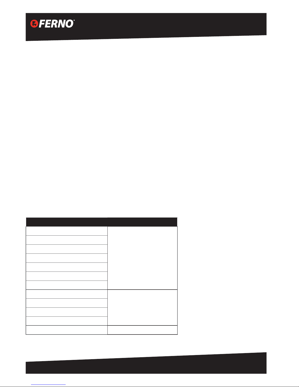
Non-metallic Components
The following table lists materials used to produce any non-metallic components on the Arachnipod.
PART MATERIAL
Standard foot tread
Polyurethane
Leg stoppers
Foot socket
Soft Ground Shoe
Lazy Leg Adapter plug
Lazy Leg extender mouldings
Bridge Pulley mouldings
Pulley Head pulley spacers
Acetal
Step spacers
Bridge Pulley spacer
Lower Leg stopper
Leg bumper Rubber

11
Arachnipod User Manual
Version 6.0
© Copyright: FERNO AUSTRALIA
Inspection of the Arachnipod
Equipment should be inspected regularly, before and after each use by a qualied person. Record the date of the
inspection and the results in the equipment log. It is also recommended to write the date of the next inspection
on the device. Each user should be trained in equipment inspection and should carry out a pre-inspection of the
equipment to ensure that it is in a serviceable condition and operates correctly before each use.
Inspect the Arachnipod for cracks, dents, or elongation of the karabiner and pin holes. The legs should t together
smoothly and should not appear bent or deformed. Pins should have the retaining hardware present and must
function freely.
Inspect plastic parts for wear or chemical damage.
Repairs
Any repair work must be done by the manufacturer or accredited agent. Any other repair work or modications will
void the warranty.
WARNING
The Arachnipod has been engineered and tested using the original equipment as supplied. Never replace any pins,
bolts or other components with non-genuine parts.
Do not use your Arachnipod if any parts are missing.
The Arachnipod must not be used outside its limitations, or for any purpose other than that for which it is
intended.
For service or repairs, please contact your local Ferno Distributor or Ferno Australia
Tel: +61 7 3881 4999
Email: sales@ferno.com.au
www.ferno.com.au
Safe Working Practices
1. Always wear relevant PPE including gloves.
2. Do not exceed the working load limit for the given application.
3. Always maintain a safety line independent of the main line.
4. All Arachnipod feet must be secured to prevent unwanted movement.
5. It is a good practice to ensure that all rigging is capable of holding the entire weight of the main load.
6. Always provide height safety and fall prevention for personnel working close to the height risk.
7. Ensure a Rescue Plan is in place to deal with any emergencies which may arise.
Australia
12
Arachnipod User Manual Version 6.1
DOC ID: 00184-AU-V06 (2015/03)
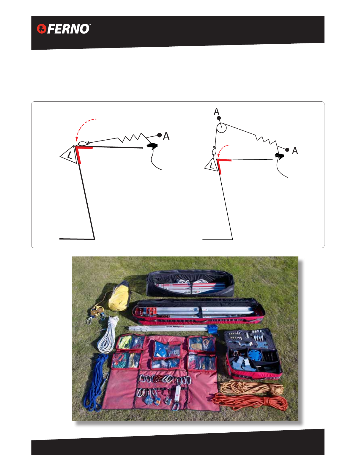
Principles of Edge Management
Edge management is the assessment of the rigging task to ensure that the load can be manoeuvred over the edge.
Rigging to provide a high change of direction is the key to successfully managing an edge. The Arachnipod is a tool
that can be used to achieve a high change of direction.
Edge
Protection
Edge
Management
Problem
Edge
Management
Solution
Edge
Protection
13
Arachnipod User Manual
Version 6.0
© Copyright: FERNO AUSTRALIA
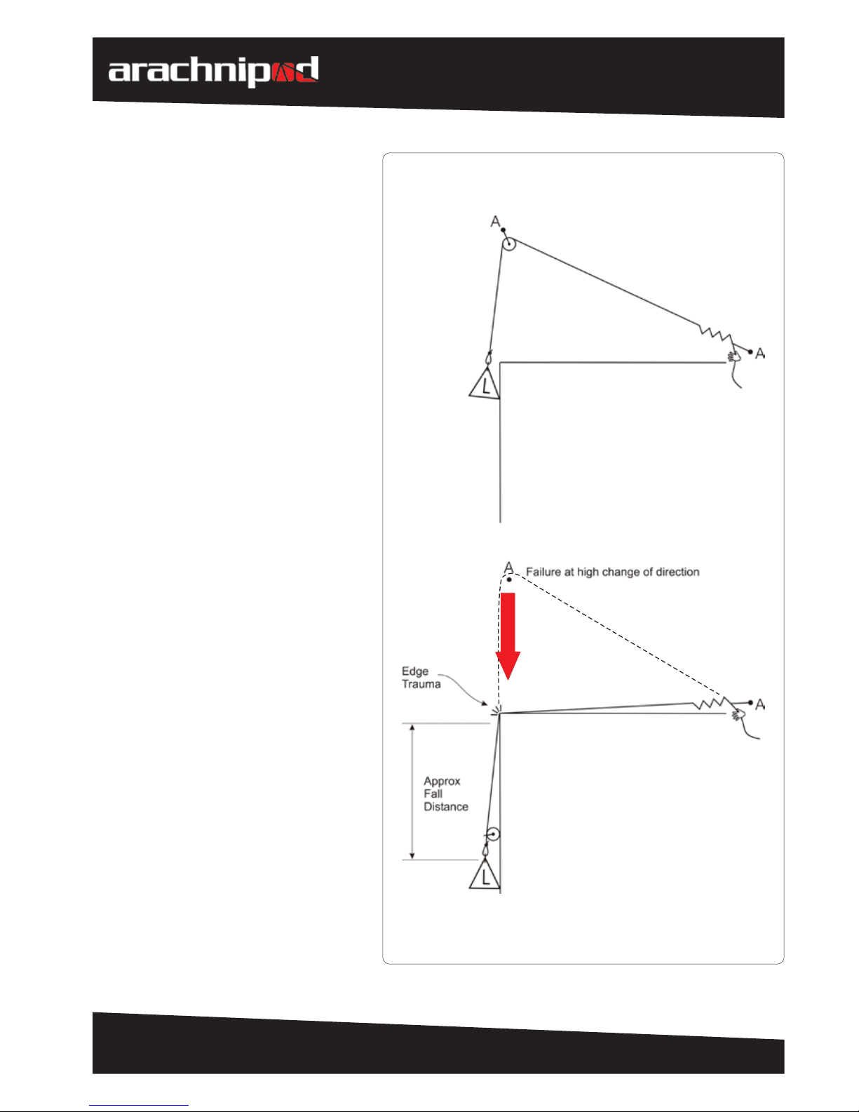
Critical Point Analysis
(High change of direction)
A critical point analysis is the assessment
of all rigging regardless of the equipment
brand or type. The purpose of a critical
point analysis is to determine if the rigging
relies on any single point to provide
operator safety.
The Arachnipod if used correctly will
provide an ecient and safe edge
management system but not all aspects
of the rigging and equipment use can be
guaranteed by the manufacturer. Many
factors such as edge instability, anchor
insecurity, misuse, persons who are not
fully competent, user error, abuse and the
use of other equipment could result in a
system failure.
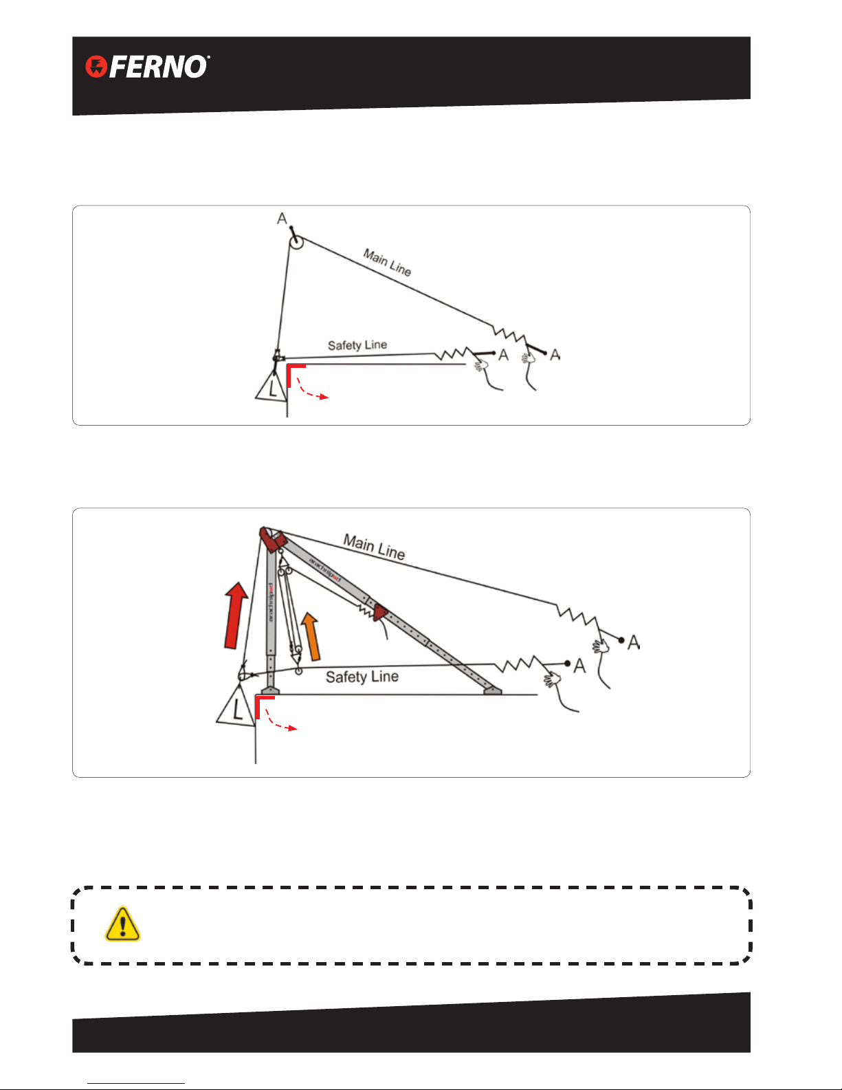
The diagram (right) shows how failure
of a high change of direction (edge
management) of a single rope system
would subject the load to a fall. The
seriousness of the fall will depend upon
many factors including the height of the
change of direction and the length of rope
that is between the load and the anchor.
Australia
14
Arachnipod User Manual Version 6.1
DOC ID: 00184-AU-V06 (2015/03)
The Two Rope System
A two rope system provides additional safety by backing up the main line and any edge management systems. The
second line or safety line is rigged to take the shortest path from the anchor to the load.
When the load is located below the edge the safety line provides protection for both main line and edge
management failures. When the load is located above the edge the safety line provides limited protection for
main line failures.
The Arachnipod can be rigged with the main line passing over the pulley head and a rated hauling system can
be used to progressively pick the safety line up as the load is raised. This process provides additional protection
against a main line failure. Ferno can supply properly rated and pre-rigged hauling systems that are suitable for
this task.
WARNING
Edge protection should also be provided to protect both lines against edge
trauma. Ferno can supply a range of edge protection solutions
Edge Protection
Edge Protection
15
Arachnipod User Manual
Version 6.0
© Copyright: FERNO AUSTRALIA
Understanding the forces being applied to the Arachnipod
The Arachnipod or any other edge management device is subjected to resultant forces and directions. To keep
edge management devices or rigging in place the resultant forces and directions being applied must be assessed
and sometimes additional rigging will be required to provide stabilisation. In simple terms, if all of the forces are
balanced then the Arachnipod will remain stable.
We can use various Arachnipod components and rigging to
balance the forces as follows:
1. The legs of the Arachnipod system are generally used to
balance compression forces,
2. Additional rigging is used to balance tension forces, and
3. Some rigging may be used to preload the
tension rigging to minimise movement created by
rope stretch and cyclic loading.
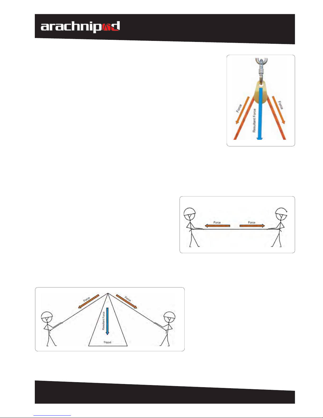
The game known as “tug of war” is a good example of balanced forces. If two people applied exactly the same
horizontal force then the rope would remain stationary. The load forces are balanced and no movement would occur.
Understanding the forces at a change of direction pulley
Most edge management tasks require the use of a pulley or pulleys to change
the direction of the load line. Correct assessment of the loads being applied to
these pulleys and the ability to determine the resultant direction is essential when
selecting the most appropriate edge management system and rigging.
An applied force has magnitude and direction. A change of direction pulley is
subjected to two forces:
1. The weight of the load, and
2. The force required to manage that load.
The force that is required to manage the load will vary because of friction.
The resultant force bisects the two applied forces. A good indicator of resultant
direction is to look at the direction of the pulley and attachment hardware.
If a tripod is placed under the tug of war
rope then the same rules would apply.
Because there is now a change of direction a
resultant force now exists.
Australia
16
Arachnipod User Manual Version 6.1
DOC ID: 00184-AU-V06 (2015/03)
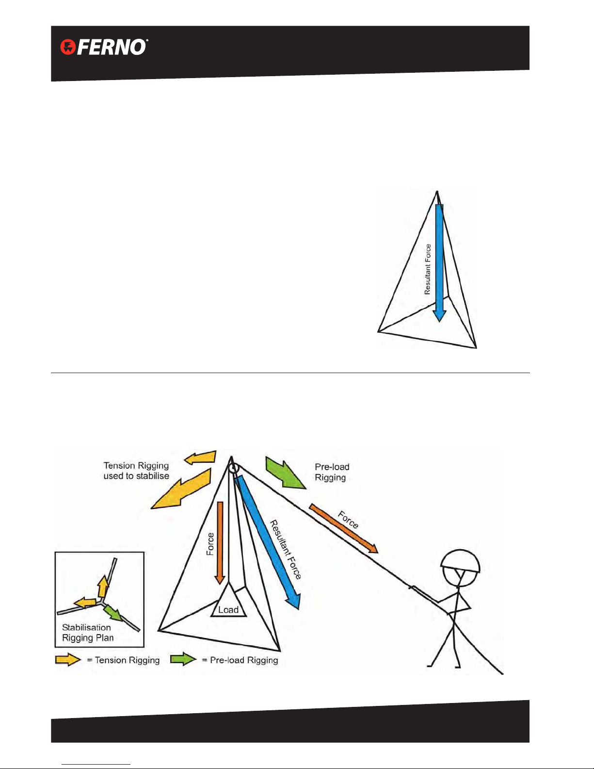
Tripod Stabilisation
Tripods make use of three legs all of which are in compression.
Some tripods applications may require additional rigging to provide
sucient stabilisation and security.
If a tripod is rigged in such a way that the resultant force and direction
are being applied downwards and if it remains within the triangular
base (the triangle formed by the leg securing rope) then the tripod will
remain stable. If the load shifts closer to any given leg then the load
being applied to that leg increases but the tripod will remain stable.
If the resultant force and direction is being applied outside of the triangular base then the tripod will become
unstable. Additional rigging will be required to maintain tripod security. Some of the rigging will remain under
tension and other rigging may be used to preload the edge management system.
Assessing the stability of your Arachnipod rigging
The following stabilisation examples will look at the resultant directions and suggest how the stability of the edge
management scenario may be managed.
Remember: an applied force has magnitude and direction. This manual will refer to resultant forces and resultant
directions.
17
Arachnipod User Manual
Version 6.0
© Copyright: FERNO AUSTRALIA
Arachnipod Parts
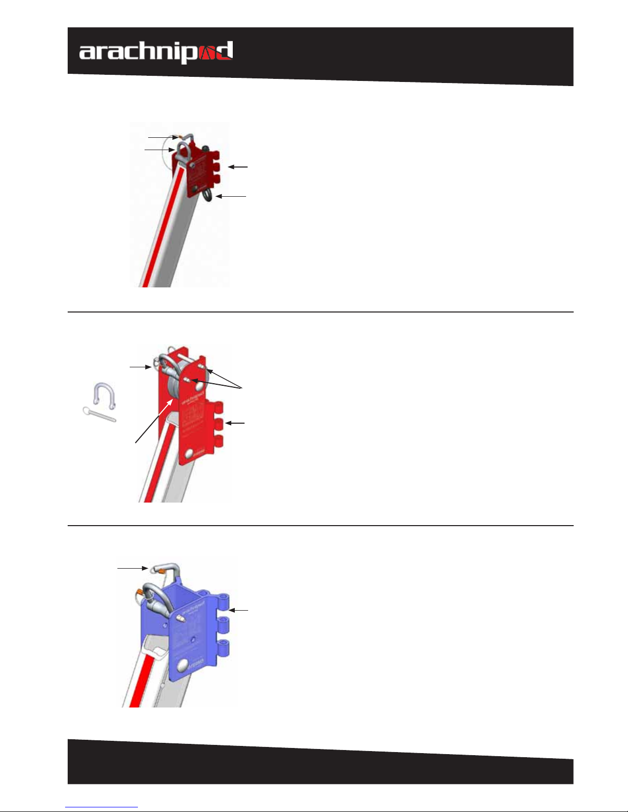
Standard Leg
Legs can be connected using Qik-link pins. The
connected joint looks much like a hinge.
A basic tripod is made up of three standard legs
joined with Qik-link pins. The removal of one Qiklink pin allows the tripod to be stored at for easy
transportation.
Rated load attachment points (eyebolts) are provided
along with an additional attachment point for
stabilisation rigging. The load attachment point can
swivel 360°.
Pulley Leg
A pulley leg can be used in place of a standard leg
to add a pulley to a tripod or A-frame conguration.
Other congurations such as a handrail technique are
also possible. (see handrail technique in this manual)
The pulley has been designed to accommodate
up to 13 mm bre rope as well as up to 8 mm (steel/
stainless steel) wire rope cable.
The stabilisation attachment point is removable.
Qik-Link Pin
Stabilisation
Attachment Point
(D-shackle)
Attachment point
for additional legs
Rated load
attachment point
with built-in
swivel (eyebolt)
Attachment point
for additional legs
Qik-Link Pin
Detent Pin is used
for the removable
stabilisation
attachment point
as well as the lock
when using the
Lazy Leg with the
Gin Head
Removable
stabilisation
attachment point
Double groove
pulley designed to
accommodate up
to 13 mm bre rope
and 8 mm wire rope
cable
Double groove
pulley designed to
accommodate up
to 13 mm bre rope
and 8 mm wire rope
cable
Attachment point
for additional legs
Detent pins are
used to prevent
ropes or cable
from escaping the
pulley grooves
 Loading...