

Page 1
Users’ Manual
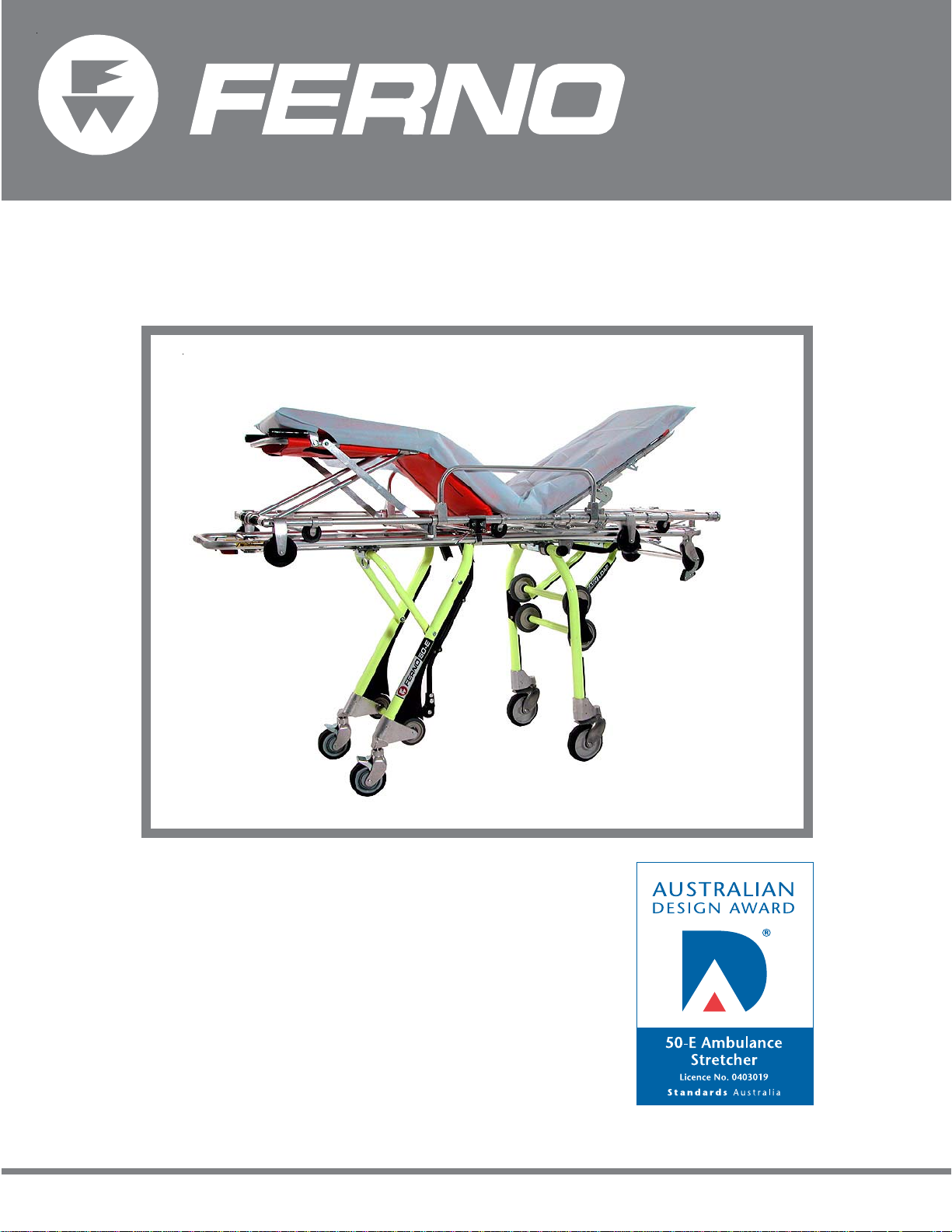
Model 50-E
Easy Load Stretcher
December 2004 INT
Pub. No. 234-3257-01
Page 2
Ferno Model 50-E
Disclaimer
This manual contains general instructions for the use, operation and
care of this product. The instructions are not all-inclusive. Safe and
proper use of this product is solely at the discretion of the user. Safety
information is included as a service to the user. All other safety
measures taken by the user should be within and under consideration
of applicable regulations. It is recommended that training on the proper
use of this product be provided before using this product in an actual
situation.
Retain this manual for future reference. Include it with the product in
the event of transfer to new users. Additional free copies are available
upon request from Customer Relations.
Proprietary Notice
The information disclosed in this manual is the property of FernoWashington, Inc., Wilmington, Ohio, USA. Ferno-Washington, Inc.
reserves all patent rights, proprietary design rights, manufacturing
rights, reproduction use rights, and sales use rights thereto, and to any
article disclosed therein except to the extent those rights are expressly
granted to others or where not applicable to vendor proprietary parts.
© Copyright Ferno-Washington, Inc. All Rights Reserved.
Ferno Australia
11 Johnstone Road
Brendale, Queensland 4500
Internet .................................. www.ferno.com.au
E-mail ..................................... info.ferno.com.au
Phone .......................................... (07) 3205.5055
Fax .............................................. (07) 3881.1125
2
© Ferno-Washington, Inc. 234-3257-01 December, 2004
Page 3

Ferno Model 50-E
TABLE OF CONTENTS
PageSection PageSection
1 - Safety Information................................................. 5, 6
1.1 Warning ................................................................ 5
1.2 Important .............................................................. 5
1.3 Bloodborne Disease Notice ................................. 5
1.4 Stretcher-Fastener Compatibility ......................... 5
1.5 Safety and Instruction Labels .............................. 6
2 - Operator Skills and T raining.................................... 7
2.1 Skills .................................................................... 7
2.2 Training ................................................................ 7
2.3 Clearance, Height & Strength Considerations..... 7
3 - About the Stretcher............................................... 8-10
3.1 Description ........................................................... 8
3.2 Vehicle Considerations ........................................ 8
3.3 General Specifications ......................................... 8
3.4 Component Specifications ................................... 9
3.5 Combined Stretcher Specifications...................... 9
3.6 Stretcher Positions ............................................. 10
4 - Model 50-E Undercarriage ................................11-14
4.1 Components ........................................................ 11
4.2 Touch Bars .......................................................... 11
4.3 Quick Fix Lock .................................................. 12
4.4 Position Control Handles ................................... 13
4.5 Foot-End Caster Wheel Locks ........................... 13
4.6 Head-End Caster Swivel Locks ......................... 14
5 - Model 155-E Stretcher Top................................ 15-18
5.1 Components ....................................................... 15
5.2 Stretcher Top Positions ...................................... 15
5.3 Changing Stretcher-Top Positions ..................... 16
5.4 Gas-Assist Backrest ........................................... 16
5.5 Side Rails ........................................................... 17
5.6 Carrying Handles - Recumbent Position ........... 17
5.7 Carrying Handles - Chair Position..................... 18
6 - Stretcher Setup.................................................... 19-23
6.1 Preparing the Stretcher for Use ......................... 19
6.2 Guidelines for Using Restraints ......................... 19
6.3 Attaching One-Piece Restraints ......................... 20
6.4 Attaching Harness Components ................... 20, 21
6.5 Adjusting Restraint Length ................................ 22
6.6 Securing the Patient ..................................... 22, 23
6.7 Unfastening the Harness .................................... 23
6.8 Removing the Restraints .................................... 23
7 - Using the Stretcher ............................................. 24-33
7.1 Before Placing the Stretcher in Service ............. 24
7.2 General Guidelines for Use ............................... 24
7.3 Attaching Stretcher Top to Undercarriage......... 25
7.4 Removing Stretcher Top from Undercarriage ... 26
7.5 Raising/Lowering the Stretcher
With Two Operators ........................................... 27
7.6 Raising/Lowering the Stretcher
With One Operator............................................. 28
7.7 Transferring the Patient ..................................... 29
7.8 Rolling the Stretcher .......................................... 30
7.9 Increasing the Loading Height ........................... 30
7.10 Loading the Stretcher Into an Ambulance ......... 31
7.11 Unloading the Stretcher from an Ambulance .... 32
7.12 Using Additional Help ....................................... 33
8 - Maintenance ........................................................34-36
8.1 Maintenance Schedule ....................................... 34
8.2 Disinfecting and Cleaning the Restraints .......... 34
8.3 Disinfecting and Cleaning the Mattress ............. 34
8.4 Disinfecting and Cleaning the Stretcher ............ 35
8.5 Waxing the Stretcher .......................................... 35
8.6 Tracker™............................................................. 35
8.7 Inspecting the Stretcher ..................................... 35
8.8 Lubricating the Stretcher ................................... 36
9 - Accessories and Related Products .......................... 37
10 - Repair Parts and Service ...................................... 38
10.1 Parts and Service - Australia .............................. 38
10.2 Parts and Service - Worldwide .......................... 38
11 - Limited Warranty .................................................. 39
12 - Ferno Customer Relations .................................... 39
T raining Record............................................................. 40
Maintenance Record ..................................................... 41
© Ferno-Washington, Inc. 234-3257-01 December, 2004 3
Page 4

ILLUSTRATIONS
Ferno Model 50-E
Safety and Instruction Labels ............................................ 6
Height and Strength Considerations.................................. 7
Stretcher Positions ........................................................... 10
Model 50-E Stretcher Components .................................. 11
Figure 1 - Touch Bars ....................................................... 11
Figure 2 - Undercarriage Head-End Hooks .................... 12
Figure 3 - Lock Bar (Bottom of Stretcher Top) .............. 12
Figure 4 - Engaging the Quick Fix Lock ......................... 12
Figure 5 - Head-End Control Handle (Red) .................... 13
Figure 6 - Foot-End Control Handles ............................. 13
Figure 7 - Engaging a Wheel Lock ................................. 13
Figure 8 - Caster Lock Release Lever ............................. 14
Figure 9 - Locking the Swivel Caster .............................. 14
Model 155-E Stretcher Top Components....................... 15
Stretcher Top Positions.................................................... 15
Figure 10 - Changing Stretcher Top Positions ................ 16
Figure 11 - Backrest Release Handle .............................. 16
Figure 12 - Using the Gas-Assist Backrest ..................... 16
Figure 13 - Using the Stretcher Top Side Rail ................ 17
Figure 14 - Telescoping Head-End Handles ................... 17
Figure 15 - Folding Foot-End Handles ........................... 17
Figure 16 - Chair Carrying Points ................................... 18
Figure 17 - Restraints Prepared for Use.......................... 19
Figure 18 - Patient Secured ............................................. 19
Figure 19 - Attaching a One-Piece Restraint
Through the Backrest .................................... 20
Figure 20 - Threading a One-Piece Restraint
Through the Seat Panel ................................. 20
Figure 21 - Positioning the Pelvis Strap.......................... 20
Figure 22 - Attaching the Pelvis Strap Bracket ............... 20
Figure 23 - Attaching a Brackrest Strap Bracket
to a Mounting Post ........................................ 21
Figure 24 - Fitting the Retaining Plug ............................. 21
Figure 25 - Adjusting Restraint Length........................... 22
Figure 26 - Fitting the Harness ........................................ 22
Figure 27 - Adjusting the Shoulder Straps ...................... 22
Figure 28 - Patient Secured ............................................. 23
Figure 29 - Removing the Harness .................................. 23
Figure 30 - Attaching the Stretcher Top .......................... 25
Figure 31 - Stretcher Top Rollers
and Undercarriage Hooks ............................. 25
Figure 32 - Engaging the Quick Fix Lock ....................... 25
Figure 33 - Disengaging the Quick Fix Lock .................. 26
Figure 34 - Removing the Stretcher Top ......................... 26
Figure 35 - Raising the Stretcher..................................... 27
Figure 36 - Lowering the Stretcher ................................. 27
Figure 37 - Lowering by One Level ................................ 28
Figure 38 - Raising by One Level ................................... 28
Figure 39 - Placing Stretcher Top Near Patient .............. 29
Figure 40 - Placing Stretcher Near Patient ..................... 29
Figure 41 - Rolling the Stretcher ..................................... 30
Figure 42 - Increasing the Loading Height ..................... 30
Figure 43 - Preparing to Load the Stretcher.................... 31
Figure 44 - Head-End Legs Folded; Foot-End
Touch Bar in Contact with Bumper .............. 31
Figure 45 - Check That Foot-End Legs Lock ................. 32
Figure 46 - Check That Head-End Legs Lock ................ 32
Using Additional Help ..................................................... 33
Maintenance Table .......................................................... 34
Figure 47 - Tracker
Lubrication Diagrams ...................................................... 36
Serial Number Locations ................................................. 39
™
........................................................ 35
4
© Ferno-Washington, Inc. 234-3257-01 December, 2004
Page 5
Ferno Model 50-E
1 - SAFETY INFORMATION
1.1 Warning
Warning notices indicate a potentially hazardous
situation which, if not avoided, could result in injury.
The following warnings appear in this manual.
!
WARNING
Untrained operators can cause injury or be
injured. Permit only trained personnel to
operate the stretcher.
Improper use of the stretcher can cause injury.
Use the stretcher only for the purpose described
in this manual.
Modifying the stretcher can cause
unpredictable operation and injury. Do not alter
or modify the stretcher to fit the ambulance.
Releasing the swivel locks increases the
possibility for the stretcher to tip. Maintain
control of the stretcher at all times.
Worn or damaged restraints can fail and cause
injury. Inspect restraints regularly. Dispose of
restraints that are worn, damaged, or have been
involved in a vehicular accident.
Improper operation can cause injury. Operate
the stretcher only as described in this manual.
An unattended patient can be injured. Stay with
the patient at all times.
An unrestrained patient can fall off the stretcher
and be injured. Use restraints to secure the
patient on the stretcher.
An improperly attached stretcher top can
separate from the undercarriage and cause
injury. Attach the stretcher top only with the
head end facing the undercarriage loading end.
An unlocked undercarriage can cause injury.
Verify that each set of legs locks when
unloading the stretcher.
Helpers can cause injury. Maintain control of
the stretcher, operate the controls, and direct
all helpers.
Helpers can be injured. Show helpers where to
grasp the stretcher to avoid pinch points.
Improper maintenance can cause injury. Maintain
the stretcher only as described in this manual.
Attaching improper items to the stretcher can
cause injury. Use only Ferno-approved items on
the stretcher.
Safety Information
!
WARNING
Improper parts and service can cause injury.
Use only Ferno parts and Ferno-approved
service on the stretcher.
Modifying the stretcher can cause injury and
damage. Use the stretcher only as designed
by Ferno.
1.2 Important
Important notices emphasize important usage or
maintenance information.
Important
The stretcher top Safe Working Load (S.W.L.)
is less than the S.W.L. for the system of
stretcher top and undercarriage. Do not exceed
the S.W.L. limits shown in this manual.
1.3 Bloodborne Disease Notice
To reduce the risk of exposure to bloodborne diseases such
as HIV-1 and hepatitis when using the stretcher, follow the
disinfecting and cleaning instructions in this manual.
1.4 Stretcher-Fastener Compatibility
For the purpose of the following notice, the 50-E and all
Ferno stretchers are included under the generic term, cot:
Combining different manufacturer’s products into a
“mixed-component” cot/cot fastener system can increase
the users’ risk of injury and damage. Ferno-Washington,
Inc. strongly recommends that only Ferno-manufactured
cots be used in Ferno-manufactured cot fasteners, and
that only Ferno-manufactured cot fasteners be used for
securing Ferno-manufactured cots in ambulances.
ANY COMBINATION OF A FERNO COT OR COT
FASTENER WITH A NON-FERNO COT OR COT
FASTENER IS MISUSE OF THE FERNO PRODUCT.
Responsibility for the outcome of known, intentional
misuse rests squarely on the misuser.
© Ferno-Washington, Inc. 234-3257-01 December, 2004 5
Page 6

Safety Information
Ferno Model 50-E
1.5 Safety and Instruction Labels
Safety and instruction labels place important information from the users’ manual on the stretcher. Read and follow
label instructions. Replace worn or damaged labels immediately. New labels are available from your Ferno distributor
(page 39). The following labels are affixed to the stretcher.
MODEL 50-E UNDERCARRIAGE LABELS
Pinch Point Label (2)
Head-End Control Label (1)
MODEL 155-E STRETCHER TOP LABELS
Identification Label - Head End (2)
Foot-End Control Label (1)
Identification Label - Foot End (2)
Quick Fix Lock Label (2)
Shock Position Release
Lever Label (2)
Backrest Control
Label (1)
Safe Working Load Information Label (1)
6
© Ferno-Washington, Inc. 234-3257-01 December, 2004
Page 7
Ferno Model 50-E
2 - OPERATOR SKILLS AND TRAINING
2.1 Skills
Operators using the stretcher need:
a working knowledge of emergency patienthandling procedures.
the ability to assist the patient.
a complete understanding of the procedures
described in this manual.
2.2 Training
Operator Skills and Training
!
WARNING
Untrained operators can cause injury or be
injured. Permit only trained personnel to
operate the stretcher.
Trainees need to:
follow a training program designed by their
training officer.
read this manual. For additional free users’
manuals, contact your Ferno distributor (page 39).
practice with the stretcher before using it in
regular service.
be tested on their understanding of the stretcher.
record their training information. A form is
provided on page 40.
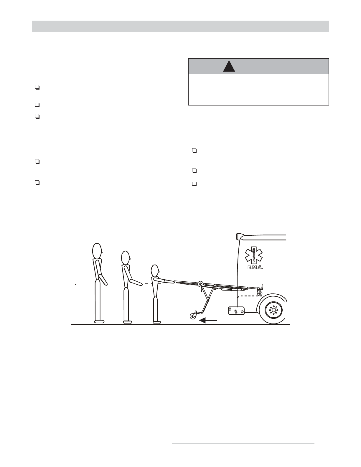
2.3 Clearance, Height, and Strength Considerations
Clearance
The Model 50-E is designed so that under normal
conditions, the operator lifts only until the rear set of
legs unfolds and locks.
However, if the ambulance is parked in a low area or on
an incline, the operator (and any helpers) may need to
lift the stretcher foot end off the ground to provide
clearance for the foot-end legs to unfold completely and
lock (see illustration above). When the legs have locked,
set the stretcher on the ground.
After the head-end legs have unfolded, test that they have
locked by pushing them gently against the ambulance
© Ferno-Washington, Inc. 234-3257-01 December, 2004 7
bumper. The legs should not fold. If they do, again lift
the stretcher off the ground to allow clearance for the
head-end legs to unfold completely and lock.
Be aware that supporting the weight of the stretcher,
patient and equipment requires greater strength from a
short operator than from a tall operator because a short
operator must raise his or her arms higher in relation to
the shoulders.
Note: Use additional help as needed when lifting the
weight of the stretcher, patient, and equipment (see Using
Additional Help, page 33).
Page 8
About the Stretcher
Ferno Model 50-E
3 - ABOUT THE STRETCHER
3.1 Description
The Model 50-E Series Easy Load Stretcher is an
emergency patient-handling device. Its components are
a Model 155-E removable stretcher top and a Model
50-E undercarriage. In this manual, the system of
stretcher top plus undercarriage will be referred to as
the “stretcher.”
The stretcher is for use by trained operators. Ferno
strongly recommends using two operators, even though
the stretcher can be operated by one trained operator.
The stretcher is designed for roll-in loading to help
reduce the risk of back injury to medical service
personnel.
STRETCHER TOP FEATURES
• Side rails
• Carrying handles
• 4 Positions (recumbent, 2 shock, and chair)
• Infinitely-adjustable gas-assist backrest
• Quick Fix lock
3.2 Vehicle Considerations
The ambulance patient compartment must have:
• A smooth, level floor large enough for the
stretcher.
• An approved, installed Ferno stretcher fastener
configured for use with the Model 50-E.
• Floor height at the specified dimension (see the
Loading Height on page 9).
If needed, modify the ambulance to fit the stretcher by
adding ramps, a folding rear step, etc. Do not alter the
stretcher or the stretcher operating procedures.
!
WARNING
Modifying the stretcher can cause
unpredictable operation and injury. Do not
alter or modify the stretcher to fit the
ambulance.
UNDERCARRIAGE FEATURES
• 5 Level positions with multi-level positioning (can
be locked into a different level at each end)
• Automatic head-end-leg safety lock touch bar
• Automatic foot-end-leg release touch bar
• 150 mm casters with swivel locks (head end)
• 125 mm casters with wheel locks (foot end)
• Loading wheels and intermediate loading wheels
!
WARNING
Improper use of the stretcher can cause
injury. Use the stretcher only for the purpose
described in this manual.
3.3 General Specifications
General specifications are rounded to the nearest whole
number.
• Stretcher-top heights are measured from the
ground with the stretcher top removed from the
undercarriage.
• Stretcher heights are measured from the ground
to the top of the stretcher top main frame.
• Weights do not include the mattress, restraints,
equipment brackets, or accessories.
• Loading height is measured from the ground to
the bottom of the front loading wheels.
Ferno reserves the right to change specifications
without notice.
8
© Ferno-Washington, Inc. 234-3257-01 December, 2004
Page 9
Ferno Model 50-E About the Stretcher
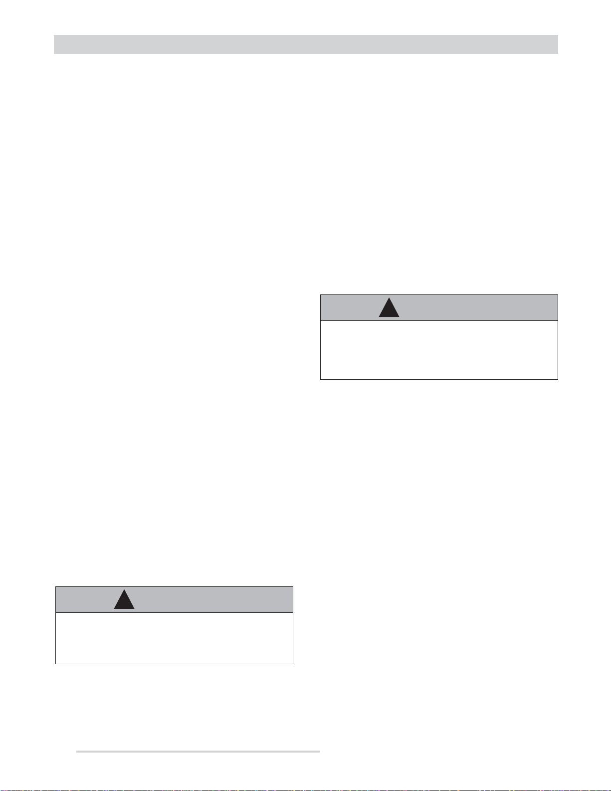
3.4 Component Specifications
155-E STRETCHER TOP (RECUMBENT POSITION)
Length (handles extended) .......................... 2360 mm
Length (handles retracted) .......................... 1960 mm
Width ............................................................. 560 mm
Height (top of side rail) ................................. 330 mm
Height (top of mattress) ................................ 230 mm
155-E STRETCHER TOP (SEATED POSITION)
Height (seat) .................................................. 580 mm
Height (back) ............................................... 1470 mm
Depth (at seat) ............................................... 710 mm
Weight ................................................................ 17 kg
Safe Working Load (S.W.L.) ........................... 159 kg
50-E UNDERCARRIAGE
Length .......................................................... 1980 mm
Width ............................................................. 560 mm
Weight ................................................................ 32 kg
159 kg
S.W.L.
LOAD LIMIT
Important
The stretcher top Safe Working Load (S.W.L.)
is less than the S.W.L. for the system of
stretcher top and undercarriage. Do not exceed
the S.W.L. limits shown in this manual.
STRETCHER TOP
SAFE WORKING LOAD
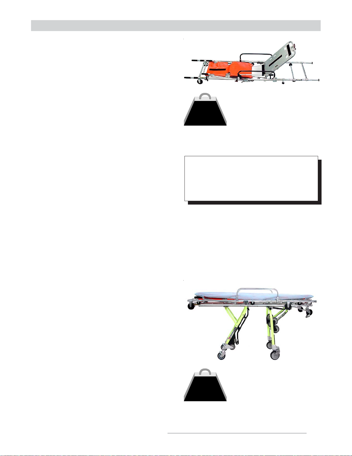
3.5 Combined Stretcher Specifications (Stretcher Top & Undercarriage)
Length .......................................................... 1980 mm
Width ............................................................. 560 mm
Loading height ............................................... 710 mm
Height
Position A ................................................ 855 mm
Position B ................................................ 762 mm
Position C ................................................ 645 mm
Position D ................................................ 427 mm
Folded ...................................................... 175 mm
Combined Weight .............................................. 49 kg
Safe Working Load (S.W.L.) ........................... 250 kg
SYSTEM
250 kg
SAFE WORKING LOAD
S.W.L.
(System = Undercarriage
LOAD LIMIT
© Ferno-Washington, Inc. 234-3257-01 December, 2004 9
plus Stretcher Top)
Page 10
About the Stretcher
3.6 Stretcher Positions
Ferno Model 50-E
175 mm
855 mm
710 mm
Loading Height
762 mm
FOLDED
POSITION A:
ROLLING/LOADING
POSITION B:
TRANSFER
10
645 mm
POSITION C:
TRANSFER
POSITION D:
427 mm
TRANSFER
© Ferno-Washington, Inc. 234-3257-01 December, 2004
Page 11
Ferno Model 50-E 50-E Undercarriage
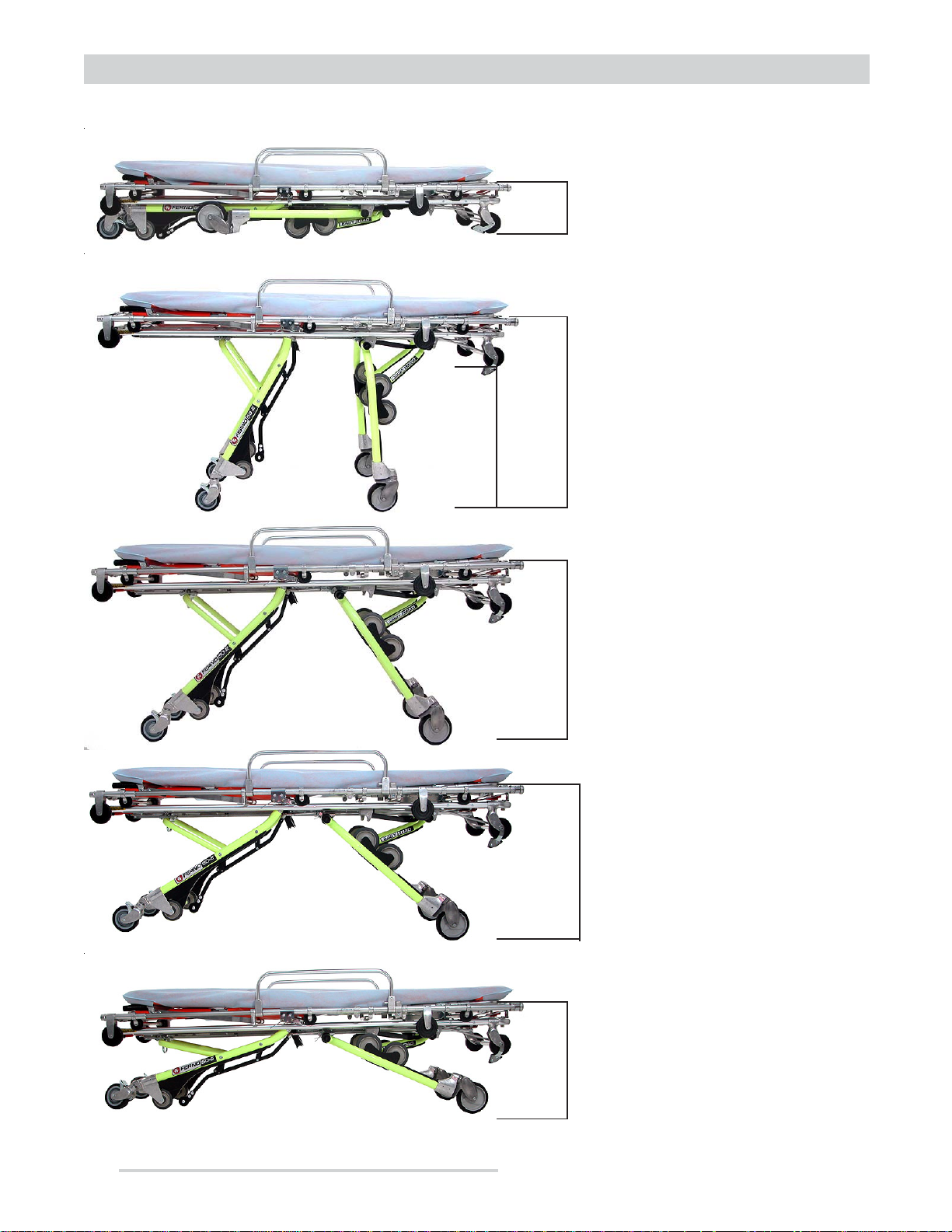
4 - MODEL 50-E UNDERCARRIAGE
4.1 Components
FOOT END
Foot-End Leg
Override Handle
Loading or Foot-End
Lowering Handle
Tracker
Head-End Quick Fix
Lock Hook (4)
HEAD END
Head-End
Lowering Handle
Swivel Lock
Release Lever
Loading
Wheel (2)
Head-End Touch Bar
Intermediate
Loading Wheel (4)
5" Swivel Wheel
with Wheel Lock (2)
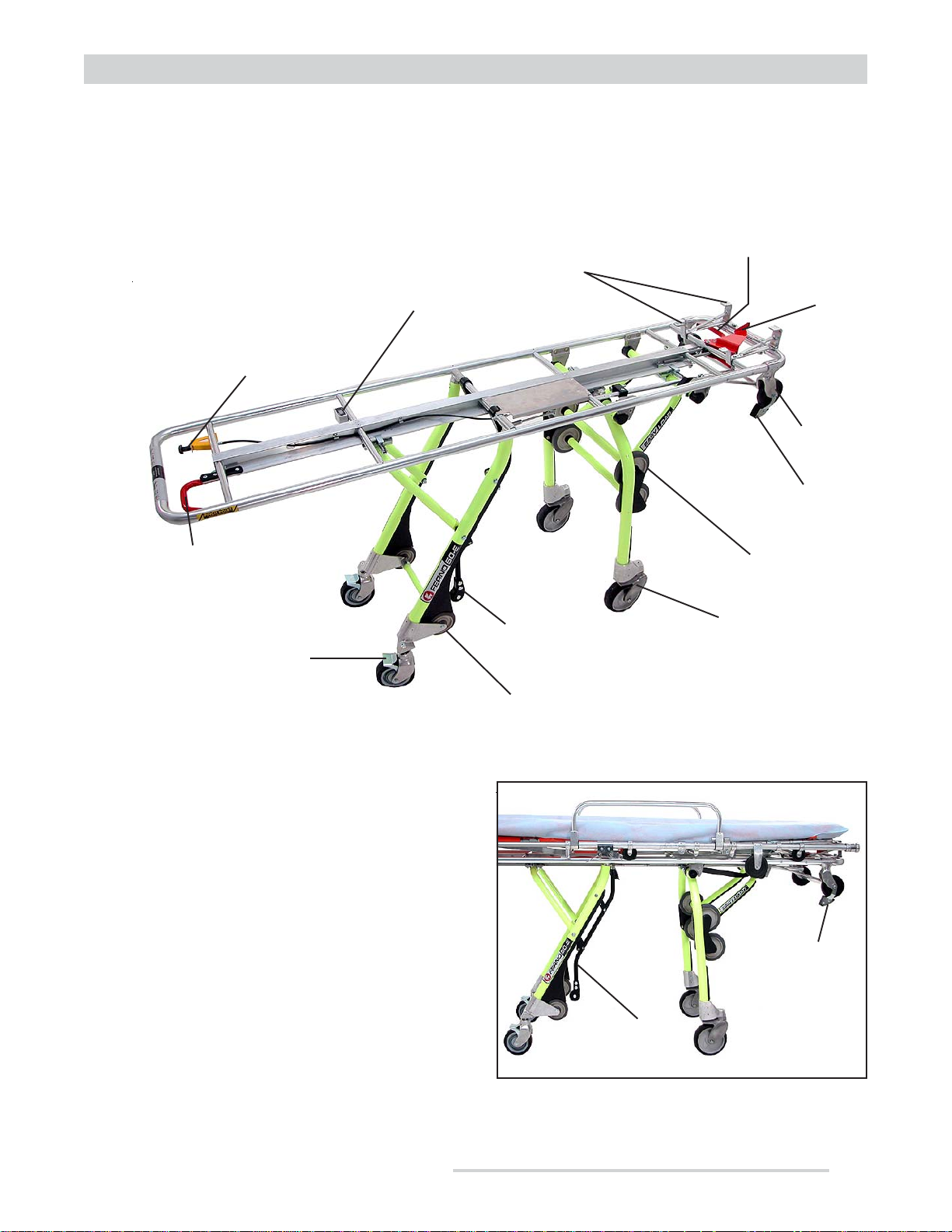
4.2 Touch Bars
The undercarriage has two touch-bar mechanisms
(Figure 1) that automatically function as the stretcher
is being loaded into an ambulance.
When the operator activates the foot-end control handle
(page 13) to load the stretcher into the ambulance, the
following events occur:
• The head-end touch bar is activated when it contacts
the ambulance floor. It releases a secondary lock and
allows the head-end legs to fold.
• The foot-end touch bar is activated when it contacts
the ambulance bumper. It unlocks the foot-end legs.
For complete loading instructions, see page 31.
Foot-End
Touch Bar
Intermediate
Loading Wheel (2)
6" Swivel Wheel (2)
Head-End
Touch Bar
Foot-End
Touch Bar
Figure 1 - Touch Bars
© Ferno-Washington, Inc. 234-3257-01 December, 2004 11
Page 12
Ferno Model 50-E50-E Undercarriage
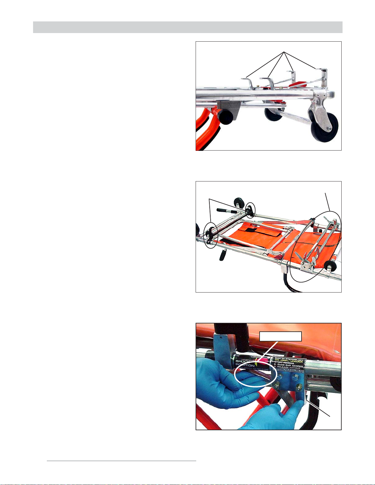
4.3 Quick Fix Lock
The Quick Fix lock is a system of hooks that secures the
stretcher top to the undercarriage. It is composed of:
• Undercarriage: 4 stationary hooks at the
head end (Figure 2)
• Stretcher top: 2 stationary foot-end hooks and
a lock bar with 2 hooks (Figure 3)
The six stationary hooks help hold the stretcher top on
the undercarriage. The lock bar secures the two
components together. Leave the lock bar disengaged
when the stretcher top is not on the undercarriage.
USING THE LOCK BAR
The lock bar is located under the stretcher top and has
two hooks that grasp the undercarriage main frame. It
is engaged by moving it across the undercarriage from
the patient left to the patient right.
OPERATOR ST ANDING ON PATIENT LEFT
Hooks
Figure 2 - Undercarriage Head-End Hooks
Foot-End
Hook (2)
Lock Bar
To engage the lock bar (Figure 4):
1. Lift the lock lever (the hooks will drop down).
2. Push the lock bar hook across the stretcher.
3. Release the lock lever.
To disengage the lock bar:
1. Lift the lock lever.
2. Pull the lock bar hook toward yourself.
3. Release the lock lever (the hooks will swing up).
OPERATOR STANDING ON PATIENT RIGHT
To engage the lock bar:
1. Lift the lock lever (the hooks will drop down).
2. Pull the lock bar tab toward yourself.
3. Release the lock lever.
To disengage the lock bar:
Figure 3 - Lock Bar (Bottom of Stretcher Top)
Lock Lever
1. Lift the lock lever.
2. Push the lock bar tab toward the stretcher center.
3. Release the lock lever (the hooks will swing up).
12
Hook
Figure 4 - Engaging the Quick Fix Lock
© Ferno-Washington, Inc. 234-3257-01 December, 2004
Page 13
Ferno Model 50-E 50-E Undercarriage
4.4 Position Control Handles
There are three control handles for lowering the
stretcher or loading it into an ambulance. Do not use
the control handles when raising the stretcher.
• To lower the stretcher head end, use the headend red control handle (Figure 5).
• To load the stretcher into an ambulance, use the
foot-end red control handle.
Note: The foot-end red contr ol handle must be activated
throughout the process of loading the stretcher into an
ambulance. F or complete instructions, see Loading the
Stretcher Into an Ambulance, page 31.
• To lower the stretcher foot end, use both the
yellow/black override handle and the foot-end
control handle (Figure 6). The override handle
bypasses the rear touch bar mechanism. Pull it
and then pull the red control handle to lower the
foot end. See Raising/Lowering the Stretcher W ith
T wo Operators, page 27 for complete instructions.
Figure 5 - Head-End Control Handle (Red)
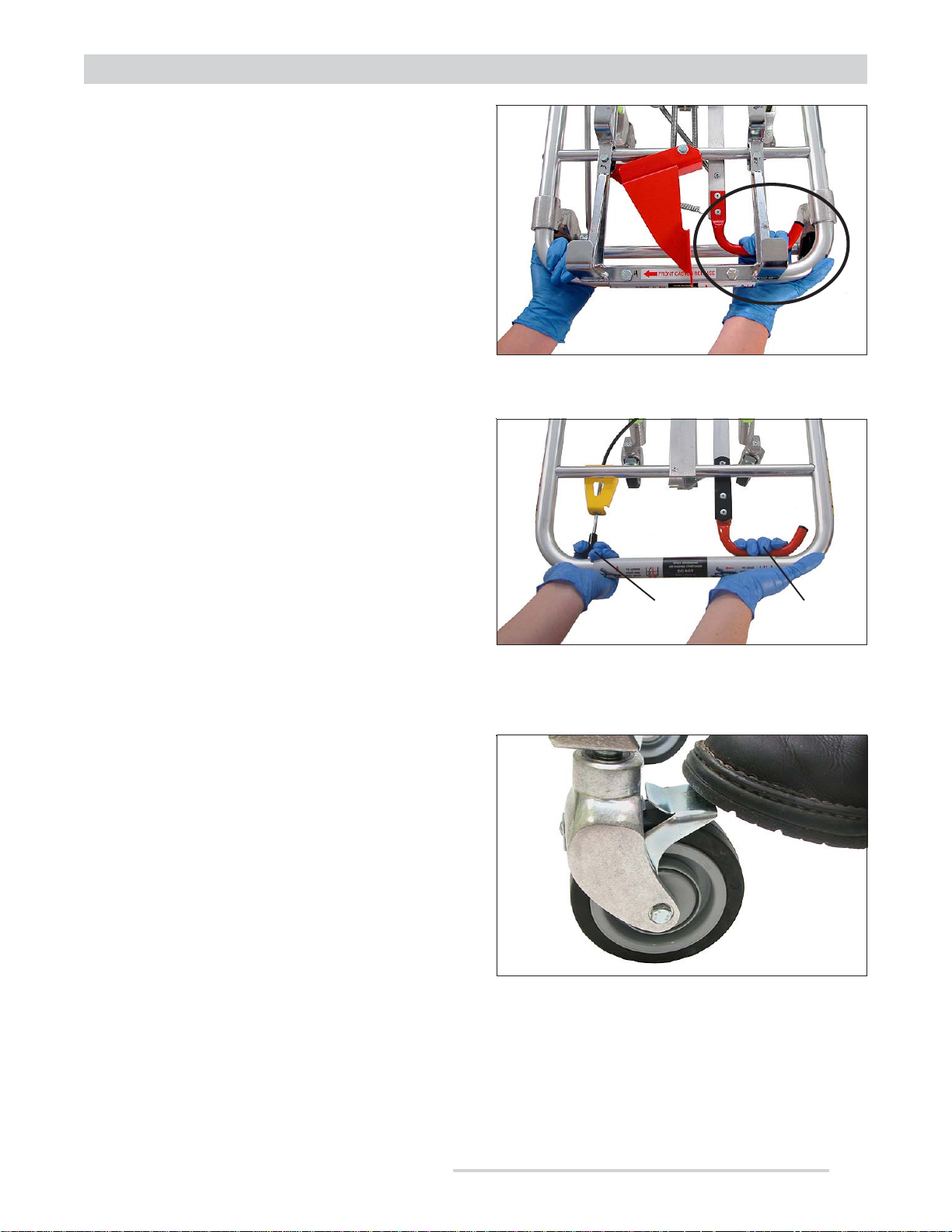
4.5 Foot-End Caster Wheel Locks
The foot end casters are fitted with wheel locks
designed to help keep the stretcher from rolling during
patient transfer and certain medical procedures.
Stay with the stretcher and maintain control of it at all
times. Do not use the wheel locks as a substitute for
operator control.
To engage a wheel lock, press the lock lever down with
your toe (Figure 7). To disengage, slide your toe under
the lever and lift it up.
Override Handle
(Yellow/Black)
Figure 6 - Foot-End Control Handles
Figure 7 - Engaging a Wheel Lock
Lower/Load
Handle (Red)
© Ferno-Washington, Inc. 234-3257-01 December, 2004 13
Page 14

4.6 Head-End Caster Swivel Locks
The stretcher’s head-end casters are locked by default.
In this condition, the wheels can roll (but not swivel)
giving the stretcher greater stability for rolling.
The operator unlocks the casters to allow the wheels to
swivel. This makes the stretcher more maneuverable.
Note: The risk of the str etcher tipping is greater when
the swivel casters are unlocked .
To unlock the casters: At the head end, swing the
release lever to the left and hold it in place (Figure 8).
This unlocks the casters and allows the wheels to swivel
freely. Hold the lever in this position as long as
additional maneuverability is needed.
Ferno Model 50-E50-E Undercarriage
Figure 8 - Caster Lock Release Lever
To lock the casters: Release the release lever and roll
the stretcher toward the head end until the wheels rotate
and lock (Figure 9).
GUIDELINES FOR USE:
The swivel lock release lever is for use only when the
stretcher is in the rolling position (see Position A, page
10). Remember to:
• Lock the casters before loading the stretcher into
an ambulance so the wheels will not swivel and
interfere with loading/unloading.
• Lock the casters before lowering the stretcher. At
a lower position, shifting weight on the stretcher
can cause an unlocked front wheel to swivel
suddenly.
Important
The head-end casters lock only when the
release handle is released and the trailing part
of each caster orients with the lock pin.
WARNING!
Releasing the swivel locks increases the
possibility for the stretcher to tip. Maintain
control of the stretcher at all times.
Swivel Caster
Lock (Metal)
14
Lock Pin
Figure 9 - Locking the Swivel Caster
© Ferno-Washington, Inc. 234-3257-01 December, 2004
Page 15

Ferno Model 50-E
5.1 Components
155-E Stretcher Top
5 - MODEL 155-E STRETCHER TOP
Chair Position
Carrying Handles
FOOT
END
Folding Foot-End
Handle (2)
Stretcher Top Position
Release Lever
Quick Fix Lock
Release Lever (2)
Integrated Side
Rail IV Pole
(optional)
Side Rail (2)
Side Rail
Release Pin (2)
Gas-Assist
Backrest Control
Handle
HEAD
END
Telescoping Head-End
Handle (2)
5.2 Stretcher T op Positions
1 - Recumbent Position
© Ferno-Washington, Inc. 234-3257-01 December, 2004 15
2 - Shock Position - Low
4 - Seated Position3 - Shock Position - High
Page 16

5.3 Changing Stretcher-Top Positions
The stretcher-top leg section has four locking positions:
recumbent, seated, and two shock positions (see
illustrations on page 15). Position changes can be made
with the stretcher top on or off the undercarriage.
To change the stretcher-top position:
1. Standing at either side of the stretcher, push the
red release lever down and lift or lower the leg
section using the lifting strap (Figure 10).
Ferno Model 50-E155-E Stretcher Top
Lifting Strap
2. When the desired position is reached, release the
release lever.
3. Raise or lower the leg section until the lock
engages.
5.4 Gas-Assist Backrest
The gas-assist backrest can be elevated to any angle
between 0º and 90º. To adjust the backrest:
1. Support the weight of the backrest and patient.
2. Lift the red control handle toward the backrest
frame and raise or lower the backrest (Figures
11 and 12).
3. Release the handle to lock the backrest.
Note: The backrest gas spring is under pressure.
Control the upwar d movement of the backr est so it does
not move too quickly.
Release
Lever
Figure 10 - Changing Stretcher-Top Positions
Release Handle
Figure 11 - Backrest Release Handle
16
Figure 12 - Using the Gas-Assist Backrest
© Ferno-Washington, Inc. 234-3257-01 December, 2004
Page 17

Ferno Model 50-E
5.5 Side Rails
The side rails provide patient security and comfort.
Keep the side rails raised except during patient
transfer. To lower, pull the lock pin (Figure 13) and
swing the side rail down. To raise, swing the side rail
up until it locks.
Important
Do not lift the stretcher by the side rails. The
side rails are not designed for lifting. Lift the
stretcher by grasping the main frame of the
stretcher or stretcher top, following the
instructions in this manual.
155-E Stretcher Top
Figure 13 - Using Stretcher-Top Side Rail
5.6 Carr ying Handles - Recumbent Position
Extend and use the carrying handles to lift and carry the stretcher top when it is in the recumbent position.
TELESCOPING HEAD-END HANDLES
T o extend: Press the detent button (Figure 14) and pull
the handle out until it locks.
T o retract: Press the detent button and push the handle
in until it locks.
To extend: Swing the handle out until the lock sleeve
snaps over the hinge.
To fold: Slide the lock sleeve toward the handle grip
and fold the handle (Figure 15).
FOLDING FOOT-END HANDLES
Detent
Button
Lock
Sleeve
Figure 15 - Folding Foot-End HandlesFigure 14 - Telescoping Head-End Handles
© Ferno-Washington, Inc. 234-3257-01 December, 2004 17
Page 18

5.7 Carr ying Handles Chair Position
To lift and carry the stretcher top in the chair position:
• The foot-end operator raises and grasps the
handles on the chair legs.
• The head-end operator grasps the crosstube,
(Figure 16), the stretcher-top main frame, or the
leg posts.
An optional stair chair handle kit (not supplied) is
available. See Accessories and Related Products,
page 37.
Ferno Model 50-E155-E Stretcher Top
Head-End
Operator Grasps:
• Crosstube
• Main Frame
• Leg Posts
Foot-End
Operator Grasps
Chair Handles
Figure 16 - Chair Carrying Points
18
© Ferno-Washington, Inc. 234-3257-01 December, 2004
Page 19

Ferno Model 50-E Setup
6 - STRETCHER SETUP
6. 1 Preparing the Stretcher for Use
Attach Australian Standards-approved restraints
as shown in this section.
Put the mattress in place.
6.2 Guidelines for Using Restraints
• Three restraints must be used to properly secure
a patient: one harness restraint (torso and pelvis
straps) and two one-piece restraints. See
Accessories and Related Products, page 37 to
order restraints.
• To meet Australian crash standards, all three
restraints must be used and attached as shown in
this manual.
• Dispose of and replace restraints that are worn,
damaged, or have been involved in a vehicular
accident. Restraints that have been involved in a
vehicular accident could have hidden damage.
Attach any accessories that will be used with the
stretcher. Follow the instructions included with
accessories. Keep accessory instruction manuals
with this manual.
Conduct a preliminary inspection of the stretcher
(See Inspecting the Stretcher, page 35).
• Unbuckle the restraints and lay the straps out of
the way before transferring the patient (Figure 17).
• Adjust restraints to safely secure the patient
without causing discomfort or impairing
circulation (Figure 18).
• Keep restraints fastened when not in use to prevent
them from interfering with stretcher operation.
!
WARNING
Worn or damaged restraints can fail and
cause injury. Inspect restraints regularly.
Dispose of restraints that are worn, damaged,
or have been involved in a vehicular accident.
Link (2)
Torso Strap
One-Piece
Restraint
(For Chest)
Harness
Cross-Strap
Harness
Pelvis Strap
One-Piece
Restraint
(For Thighs)
Figure 17 - Restraints Prepared for Use
Harness
(2)
One-Piece
Restraint
(For Chest)
Harness
Restraint
One-Piece
Restraint
(For Thighs)
Figure 18 - Patient Secured
© Ferno-Washington, Inc. 234-3257-01 December, 2004 19
Page 20

Ferno Model 50-ESetup
6.3 Attaching One-Piece Restraints
Weave the one-piece restraints through the backrest and
leg section as follows:
1. Unbuckle the restraints, raise the backrest and
place the leg section in the highest shock position.
2. Pass a buckle through one backrest slot from back
to front, pull it across the backrest panel and pass
it through the other slot (Figure 19).
3. Partially unzip the fabric cover on the leg section.
4. Thread a buckle through a slot in the cover, pass
it inside the cover and through the slot on the other
side (Figure 20).
5. Zip the cover closed.
6.4 Attaching Harness Components
The harness has two components: a shoulder harness
and a pelvis strap.
A TT ACH THE PEL VIS STRAP
1. Position the pelvis strap on the seat panel and
make sure the straps are not twisted.
2. Hook the metal bracket to the mounting post on
the main frame. Pull the bracket to seat the post
in the bracket (Figures 21 and 22).
3. Repeat Step 2 to attach the other half of the
restraint to the post on the opposite side of the
stretcher top.
Figure 19 - Attaching a One-Piece Restraint
Through the Backrest
Figure 20 - Threading a One-Piece Restraint
Through the Seat Panel
(Post Not
Shown)
Figure 21 - Positioning the Pelvis Strap
Post
Figure 22 - Attaching the Pelvis Strap
Bracket
20
© Ferno-Washington, Inc. 234-3257-01 December, 2004
Page 21

Ferno Model 50-E Setup
A TT ACH THE MA TTRESS
1. Make sure the one-piece restraints and the pelvis
strap are unbuckled and the ends of the straps
positioned out of the way.
2. Fit the mattress and linen to the stretcher top.
Post
A TT ACH THE HARNESS
1. Position the harness as shown in Figure 17 on
page 19 with:
• the torso straps and links facing the head end.
Figure 23 - Attaching a Backrest Strap
• the cross-strap brackets near the posts on the
backrest.
2. Hook the cross strap-brackets to the posts on each
side of the backrest frame. Pull the brackets to
seat the posts in the brackets (Figure 23).
Bracket to a Mounting Post
3. Push the black retaining plugs into the metal
brackets to secure the brackets to the stretcher
top frame (Figure 24).
Figure 24 - Fitting the Retaining Plug
© Ferno-Washington, Inc. 234-3257-01 December, 2004 21
Page 22

Setup
6.5 Adjusting Restraint Length
To lengthen a restraint, unbuckle it and turn the tang
perpendicular to the restraint webbing (Figure 25-A).
Pull the tang away from the restraint anchorage until
the restraint is the desired length.
To shorten a restraint, grasp the hemmed tab of the loose
end of the restraint (Figure 25-B) and pull the webbing
through the tang until the restraint is the desired length.
6.6 Securing the Patient
1. Transfer the patient following Steps 1-4 of
Transferring the Patient, page 29.
Ferno Model 50-E
Tang
25-A - Lengthening
Figure 25 - Adjusting Restraint Length
25-B - Shortening
2. Lengthen the shoulder and pelvis straps as needed.
3. Pull the harness straps over the patient’s head.
Position the two shoulder strap links on top of
one another (Figure 26).
4. Buckle the restraint by sliding the tang through
both links and into the receiver slot until it locks
into place (Figure 26).
5. Adjust the shoulder straps so they are snug against
the patient’s shoulders (Figure 27).
Important
Position the buckle and tangs centrally on the
patient’s torso for adults 14 years and older or
46 kg or over.
Position the buckle and tangs centrally on the
bony area of the pelvis for children ages 3-14
years and 14-46 kg.
LinksTang Buckle
Figure 26 - Fitting the Harness
22
Figure 27 - Adjusting the Shoulder Straps
© Ferno-Washington, Inc. 234-3257-01 December, 2004
Page 23

Ferno Model 50-E Setup
6. Fasten the two one-piece restraints across the
patient’s chest (but under the arms) and thighs
(Figure 28).
7. Make sure the buckles are securely fastened and
make further adjustments to the three restraints
to assure they safely secure the patient without
causing discomfort or impairing circulation.
6.7 Unfastening the Harness
The harness is designed for quick removal to make
patient transfers easier. If the bedding will be used to
transfer the patient, remove the shoulder harness but
leave the other straps attached to the stretcher top.
To remove the shoulder harness with the patient on the
stretcher top:
1. Unfasten all three restraints and place the ends
out of the way.
2. Pull the shoulder straps over the patient’s head
and place them clear of the patient.
3. Remove the retaining plug from the harness by
pulling on the tag attached to the plug. Unhook
the bracket from the post and remove.
4. Pull the harness straps toward the head end and
carefully slide the straps from under the patient.
Follow your local protocols (Figure 29).
5. Transfer the patient following approved EMS
procedures and your local protocols.
6.8 Removing the Restraints
To remove the harness completely for cleaning:
1. Follow the instructions in Unfastening the
Harness above.
Figure 28 - Patient Secured
2. Unhook the pelvis strap brackets from the posts.
3. Remove the one-piece restraints by unthreading
the restraints from the backrest and leg section.
© Ferno-Washington, Inc. 234-3257-01 December, 2004 23
Figure 29 - Removing the Harness
Page 24

Using the Stretcher
7 - USING THE STRETCHER
7.1 Before Placing the Stretcher
in Service
Personnel who will work with the stretcher must be
trained. See Operator Skills and Training, page 7.
Set up and inspect the stretcher. Follow the
instructions in Stretcher Setup, pages 19-23.
Ferno Model 50-E
!
WARNING
Improper operation can cause injury. Operate
the stretcher only as described in this manual.
!
WARNING
7.2 General Guidelines for Use
• Using the stretcher requires a minimum of one
trained operator. Additional operators and helpers
may be needed in some circumstances. Ferno
strongly recommends that two operators
control the stretcher when a patient is on it.
• Operators may need help when working with
heavy loads (patient and equipment). See Using
Additional Help, page 33.
• Follow standard emergency patient-handling
procedures when operating the stretcher.
• Stay with the patient at all times.
• Always use patient restraints.
• When changing the stretcher’s position or when
unloading it from an ambulance, make sure each
set of legs locks before you release your grasp on
the main frame.
• Read the stretcher fastener users’ manual for
instructions on using the fastener. See also
Stretcher-Fastener Compatibility, page 5.
An unattended patient can be injured. Stay
with the patient at all times.
!
WARNING
An unrestrained patient can fall off the
stretcher and be injured. Use restraints to
secure the patient on the stretcher.
24
© Ferno-Washington, Inc. 234-3257-01 December, 2004
Page 25

Ferno Model 50-E
7.3 Attaching the Stretcher Top
To the Undercarriage
The stretcher top attaches to the undercarriage with its
head end at the undercarriage loading end. It cannot be
attached properly in reverse. Attach the stretcher top
only as described in this manual.
Attaching the stretcher top to the undercarriage requires
a minimum of two operators working together.
1. Place the stretcher top in the recumbent position.
The stretcher top cannot be secured to the
undercarriage when it is in the seated position.
2. Make sure the Quick Fix lock is unlocked.
3. Place the stretcher top on the undercarriage:
• with the foot end extending past the
undercarriage foot end (Figure 30).
• with the stretcher top clear of the undercarriage
head-end hooks (Figure 30).
Using the Stretcher
!
WARNING
An improperly attached stretcher top can
separate from the undercarriage and cause
injury. Attach the stretcher top only with the
head end facing the undercarriage loading end.
Push Stretcher Top
Against Hooks
Push Undercarriage Slightly
Figure 30 - Attaching the Stretcher Top
• with the rollers resting on the undercarriage
frame (Figure 31).
4. Foot-End Operator: Push the stretcher top
toward the head end of the undercarriage until
the four hooks on the undercarriage engage the
head-end of the stretcher top (Figure 31) and the
two hooks hanging from the foot end of the
stretcher top engage the undercarriage main
frame.
Head-End Operator: Assist the Foot-End
Operator by holding the undercarriage steady or
pushing the undercarriage slightly toward the
Foot-End Operator.
5. Either Operator: Move to the side of the stretcher
and engage the Quick Fix lock to secure the
stretcher top to the undercarriage (Figure 32). See
Quick Fix Lock, page 12.
6. Both Operators: Verify that the stretcher top is
secure on the undercarriage.
Stretcher Top
Rollers on Frame
Figure 31 - Stretcher Top Rollers
and Undercarriage Hooks
All Four Hooks
Capture Crosstubes
Figure 32 - Engaging the Quick Fix Lock
© Ferno-Washington, Inc. 234-3257-01 December, 2004 25
Page 26

Using the Stretcher
7.4 Removing the Stretcher Top
From the Undercarriage
Removing the stretcher top from the undercarriage
requires a minimum of two operators working together.
1. Disengage the Quick Fix lock (Figure 33). See
Quick Fix Lock, page 12 for complete instructions.
2. Both Operators: Extend the stretcher-top carrying
handles.
3. F oot-End Oper ator: Pull the stretcher top toward
yourself until the hooks on the stretcher top and
undercarriage are disengaged.
Head-End Operator: Hold the undercarriage
steady or pull it slightly away from the Foot-End
Operator, as needed.
4. Both Operators: Lift the stretcher top off the
undercarriage (Figure 34). Use additional help as
needed (see Using Additional Help, page 33).
Ferno Model 50-E
Figure 33 - Disengaging the Quick Fix Lock
5. Leave the Quick Fix lock unlocked so the
undercarriage is ready when you wish to reattach
the stretcher top.
Figure 34 - Removing the Stretcher Top
26
© Ferno-Washington, Inc. 234-3257-01 December, 2004
Page 27

Ferno Model 50-E
Using the Stretcher
7.5 Raising and Lowering the
Stretcher With Two Operators
GENERAL RAISING/LOWERING GUIDELINES
• Engage the front swivel locks so the wheels will
not swivel. See Head-End Caster Swivel Locks,
page 14.
• Stand at opposite ends of the stretcher. Always
use an underhand (palms up) grip and grasp the
stretcher main frame.
• Use a second operator whenever possible. Use
additional operators and helpers when necessary.
See Using Additional Help, page 33.
• Communicate with one another and raise or lower
the stretcher together.
RAISING THE STRETCHER
Do not use control handles when raising the stretcher.
1. Both Operators: Grasp the stretcher main frame
with an underhand grasp, or extend and use the
stretcher top handles (Figure 35).
2. Both Operators: Raise the stretcher until the legs
lock at the desired position. Maintain your grasp
until you verify that both sets of legs have locked.
LOWERING THE STRETCHER
1. Both Operators: Grasp the stretcher main frame
with your hands positioned to use the control
handles (Figure 36).
2. Lift the weight of the stretcher off the wheels
while allowing the wheels to remain on the
ground. This ensures you are supporting the
weight of the stretcher, patient and equipment
before you use the control handles.
Important
Expect, and be prepared to control, the normal
downward movement of the stretcher that
occurs when the control handles are used.
3. Head-End Operator: Squeeze the red control
handle and begin lowering the stretcher.
4. Foot-End Operator: Pull the yellow override
handle and then squeeze the red control handle
and begin lowering the stretcher.
5. Both Operators: Release the control handles when
the stretcher is near its desired position. Continue
lowering the stretcher until it locks into position.
Figure 35 - Raising the Stretcher
© Ferno-Washington, Inc. 234-3257-01 December, 2004 27
Figure 36 - Lowering the Stretcher
Page 28

Using the Stretcher
7.6 Raising and Lowering the
Stretcher With One Operator
Ferno recommends two trained operators raise and
lower the stretcher unless local protocols permit one
operator to change stretcher levels.
The proper procedure for a single operator to change
levels when a patient is on the stretcher is to raise or
lower the stretcher one level at one end, then raise or
lower the other end an equal amount. Repeat until the
stretcher is level and at the desired height.
Raising or lowering by more than one level can
compromise the patient’s safety and comfort.
LOWERING
1. Stand at one end of the stretcher and grasp the
main frame with an underhand grip.
2. Lower the end of the stretcher one level (Figure 37).
Ferno Model 50-E
One Level Only
Figure 37 - Lowering by One Level
• If at the head end, squeeze the control handle.
• If at the foot end, squeeze the yellow/black
override handle and the red control handle
3. Release the control handle(s) and verify that the
stretcher has locked into position.
4. Move to the opposite end of the stretcher and
repeat Steps 1-3 until the stretcher is level and at
the desired height.
RAISING
Do not use the control handles to raise the stretcher.
1. Stand at one end of the stretcher and grasp the
main frame with an underhand grip, or extend and
use the stretcher top handles.
2. Lift the end of the stretcher one level (Figure 38).
3. Verify that the stretcher has locked into position.
4. Move to the opposite end of the stretcher and
repeat Steps 1-3 until the stretcher is level and at
the desired height.
One Level Only
Figure 38 - Raising by One Level
28
© Ferno-Washington, Inc. 234-3257-01 December, 2004
Page 29

Ferno Model 50-E
7.7 Transferring the Patient
In general, place the stretcher top or stretcher as close
to the patient as possible to minimize lifting and moving.
Follow your local protocols and the instructions below.
Note: When using the stretcher top detached from
the undercarriage, remember that the Safe Working
Load of the stretcher top is less than that of the
system of stretcher top and undercarriage. Do not
exceed the S.W.L.
1. Place the stretcher top near the patient (Figure
39) or roll the stretcher to the patient and adjust
it to the patient’s level (Figure 40).
2. Unfasten the restraints, lower the side rails, and
position the restraint straps so they will not
interfere with transferring the patient.
3. Transfer the patient onto the stretcher top using
approved EMS procedures and your local
protocols.
4. Raise the side rails, adjust the backrest and/or leg
section as needed and fasten and adjust the
restraints.
Using the Stretcher
Figure 39 - Placing the Stretcher Top
Near the Patient
Important
The stretcher top Safe Working Load (S.W.L.)
is less than the S.W.L. for the system of
stretcher top and undercarriage. Do not exceed
the S.W.L. limits shown in this manual.
5. If you removed the stretcher top, both operators
and any helpers lift and carry the stretcher top
and attach it to the undercarriage (see Attaching
the Stretcher Top to the Undercarriage, page 25).
Figure 40 - Placing the Stretcher
Near the Patient
© Ferno-Washington, Inc. 234-3257-01 December, 2004 29
Page 30

Using the Stretcher
7.8 Rolling the Stretcher
GENERAL GUIDELINES
• Rolling the stretcher with a patient on it requires
a minimum of two trained operators unless local
protocols permit one operator to roll the stretcher.
• Use help as needed to safely control the weight of
the patient, stretcher, and accessories or
equipment. See Using Additional Help, page 33.
• Roll the stretcher on smooth, unobstructed
surfaces whenever possible.
• To cross low obstacles such as door sills, lift the
weight slightly off the wheels to allow them to roll
smoothly over the obstacle.
• Lift and carry the stretcher over high obstacles.
ROLLING THE STRETCHER
Ferno Model 50-E
Figure 41 - Rolling the Stretcher
1. Make sure the restraints are securely fastened
around the patient.
2. Both Operators: Raise the stretcher to the rolling
position. See Stretcher Positions, page 10.
3. Foot-End Operator: Grasp the main frame and
pull the stretcher (Figure 41).
4. Head-End Operator: Position yourself at the side
of the stretcher near the patient’s head, or at the
head end of the stretcher and grasp the main
frame. Attend the patient and assist in rolling and
steering the stretcher (Figure 41).
7.9 Increasing the Loading Height
The preferred way to load the stretcher into an
ambulance is with the stretcher in the highest position.
In some cases such as uneven ground or when the
ambulance is parked on an incline, loading in this
position is difficult.
Important
Roll the stretcher downhill foot-end first.
If it is not medically appropriate to do this, roll
the stretcher head-end first, but have the HeadEnd Operator exert upward force on the main
frame to help maintain stretcher balance.
One Level Only
If the loading wheels do not easily roll onto the
ambulance floor, increase the loading height by lowering
the foot end one position (Figure 42). Then, load the
stretcher following the instructions on page 31.
30
Figure 42 - Increasing the Loading Height
© Ferno-Washington, Inc. 234-3257-01 December, 2004
Page 31

Ferno Model 50-E
7.10 Loading the Stretcher
Into an Ambulance
Ferno strongly recommends using two operators to load
the stretcher into an ambulance. The stretcher can be
loaded by one trained operator if local protocols permit.
Use additional help as needed (see Using Additional
Help, page 33).
1. Raise the stretcher to its highest position and make
sure the front casters are locked so they will not
swivel as the stretcher is loaded.
2. If the ambulance has a folding bumper, raise it.
3. Roll the stretcher into the open ambulance
doorway until both loading wheels are on the
patient compartment floor and the head-end legs
contact the bumper (Figure 43). If the floor is too
high, see Increasing the Loading Height, page 30.
Using the Stretcher
Figure 43 - Preparing to Load the Stretcher
Important
4. Foot-End Operator: Grasp the main frame using
an underhand (palms up) grip, and support the
stretcher but do not lift it.
5. Foot-End Operator: Squeeze and hold the red
control handle and begin pushing the stretcher
into the ambulance. The head-end legs will fold.
6. Foot-End Operator: Continue pushing the
stretcher into the ambulance. Be prepared to
assume the remaining weight of the stretcher
when the foot-end touch bar contacts the
ambulance bumper (Figure 44) and unlocks the
foot-end legs.
Note: If you let go of the lowering handle, the footend legs will not fold when the touch-bar contacts
the ambulance bumper. Squeeze and hold the
lowering handle throughout the loading process.
7. Foot-End Operator: Finish pushing the stretcher
into the ambulance. Release the control handle.
8. Secure the stretcher in the vehicle using an
approved Ferno fastener.
Check the position of the casters when loading.
Front casters must be locked (no swivel).
Rear caster locks should face the ground as
the stretcher is loaded. If not, they can contact
the operator's hand during loading.
Operator Continues
Squeezing the
Control Handle
Foot-End Touch Bar
Contacts Bumper
Figure 44 - Head-End Legs Folded,
Foot-End Touch Bar in Contact with Bumper
© Ferno-Washington, Inc. 234-3257-01 December, 2004 31
Page 32

7.11 Unloading the Stretcher
From an Ambulance
Ferno strongly recommends using two operators to
unload the stretcher from an ambulance. The stretcher
can be unloaded by one trained operator if local
protocols permit. Use additional help as needed (see
Using Additional Help, page 33).
Do not use the control handles while unloading the
stretcher.
1. If the ambulance has a folding bumper, raise it.
2. Release the stretcher from the stretcher fastener.
3. Foot-End Operator: Grasp the stretcher main
frame and support the stretcher as you begin
pulling it from the ambulance.
Ferno Model 50-EUsing the Stretcher
Figure 45 - Check That Foot-End Legs Lock
4. Foot-End Operator: Allow the foot-end legs to
unfold completely and lock into place (Figure 45).
If the ambulance is parked in a low area or on an
incline, you may need to lift the stretcher off the
ground to allow clearance for the legs to unfold
completely and lock.
5. Foot-End Operator: With the rear wheels on the
ground, continue pulling the stretcher from the
ambulance until the head-end legs unfold
completely and lock (Figure 46). Keep the loading
wheels on the ambulance floor until you complete
Step 6.
6. Verify that the head-end legs have locked by
lightly pushing the stretcher against the
ambulance bumper without using any control
handles. If the legs do not fold, they are locked
and you can continue to Step 7.
If the head-end legs fold, lift the stretcher off the
ground. Lifting allows clearance for the head-end
legs to unfold completely and lock.
!
WARNING
An unlocked undercarriage can cause injury.
Verify that each set of legs locks when
unloading the stretcher.
Important
If the ambulance is in a low area or on an incline,
the operators (and any helpers) may need to lift
the stretcher off the ground to allow clearance
for the legs to unfold completely and lock.
7. Finish pulling the stretcher out of the ambulance.
32
Figure 46 - Check That Head-End Legs Lock
© Ferno-Washington, Inc. 234-3257-01 December, 2004
Page 33

Ferno Model 50-E
Using the Stretcher
7.12 Using Additional Help
Operating the stretcher requires a minimum of one trained operator, but Ferno strongly recommends that the stretcher
be operated by two trained operators. Additional help may be needed when working with heavy loads (patient,
accessories and equipment). Operators should maintain control of the stretcher, operate the controls, and direct
helpers. The chart below shows suggested placement for operators and helpers.
Inspect the stretcher if the load limit has been exceeded (See Inspecting the Stretcher, page 35).
Helpers Loading/UnloadingRolling
Two
Operators
+
Two
Helpers
Two
Operators
+
Four
Helpers
Changing Levels
Key: O = Operator H = Helper P = Patient
!
WARNING
Helpers can cause injury. Maintain control of
the stretcher, operate the controls, and direct
all helpers.
159 kg
S.W.L.
LOAD LIMIT
STRETCHER TOP
SAFE WORKING LOAD
SAFE WORKING LO AD
250 kg
S.W.L.
LOAD LIMIT
SYSTEM
WARNING!
Important
Helpers can be injured. Show helpers where
to grasp the stretcher to avoid pinch points.
© Ferno-Washington, Inc. 234-3257-01 December, 2004 33
The stretcher top Safe Working Load (S.W.L.)
is less than the S.W.L. for the system of
stretcher top and undercarriage. Do not exceed
the S.W.L. limits shown in this manual.
Page 34

Maintenance
8.1 Maintenance Schedule
Ferno Model 50-E
8 - MAINTENANCE
The stretcher requires regular maintenance. Set up
and follow a maintenance schedule. A sample form
is provided on page 41. The table at right represents
minimum intervals for maintenance.
When using maintenance products, follow the
manufacturers’ directions and read the manufacturers’
material safety data sheets. Contact your Ferno distributor
to order Ferno-recommended disinfectant (page 39).
8.2 Disinfecting and Cleaning
the Restraints
1. Remove restraints from stretcher.
2. Spray metal components with disinfectant cleaner
and wipe with clean cloth, following disinfectant
manufacturer’s instructions. Do not immerse
buckles in liquid.
3. Add a disinfectant cleaner to warm water,
following instructions on container.
4. Immerse restraint webbing in disinfectant
solution for the time directed in the disinfectant
manufacturer’s instructions. Do not immerse the
buckles.
5. Repeatedly dip restraint webbing in clear water
to rinse. Do not immerse buckles.
Minimum
Maintenance Intervals
Disinfecting (pages 34-35)
Cleaning (pages 34-35)
Waxing (page 35)
Inspecting (page 35)
Lubricating (page 36)
!
WARNING
Improper maintenance can cause injury.
Maintain the stretcher only as described in
this manual.
Each Use
As Needed
•
•
•
•
•
Important
Disinfectants and cleaners containing bleach,
phenolics, or iodines can cause damage.
Disinfect and clean only with products that do
not contain these chemicals.
Each Month
•
6. Hang restraints to dry.
7. Attach clean, dry restraints to stretcher as
described in Stretcher Setup, pages 19-23.
8.3 Disinfecting and Cleaning
the Mattress
1. Remove the mattress from the stretcher.
2. Wipe all surfaces of the mattress with disinfectant,
following the disinfectant manufacturer’s
instructions.
3. Wash the mattress with warm, soapy water and a
soft cloth.
4. Rinse the mattress with clear water.
5. Dry the mattress with a towel.
34
Important
Metal buckles on restraints can be damaged by
immersion in liquids or by washing machine
action. Disinfect and clean restraints only as
directed in this manual.
© Ferno-Washington, Inc. 234-3257-01 December, 2004
Page 35

Ferno Model 50-E
Maintenance
8.4 Disinfecting and Cleaning
the Stretcher
To disinfect: Wipe all surfaces with disinfectant,
following the disinfectant manufacturer’s directions.
Ferno recommends that you inspect the stretcher for
obvious damage as you disinfect it.
To clean: Hand wash all parts of the stretcher with
warm water and a mild detergent. Use a stiff brush (but
not a metal wire brush) to remove stains.
8.5 Waxing the Stretcher
Disinfect and clean the stretcher before applying wax.
Use an automotive wax as directed by the wax
manufacturer.
8.6 Tracker
™
Important
Water under high pressure penetrates joints,
flushes away lubricant, and causes corrosion.
Do not use a high-pressure washer, or steam,
to clean the stretcher.
Important
Using abrasive cleaning compounds or applicators
on the stretcher frame can cause damage. Do not
use abrasive materials to clean the stretcher.
The Tracker™ is attached to the undercarriage and
counts stretcher cycles. A cycle equals raising the
stretcher from the folded position to a raised position
and back. The total number of cycles is displayed on
an LCD readout (Figure 47).
Use the Tracker as an aid to schedule and record
stretcher maintenance.
Note: The Tracker is designed to maintain a count of
the total number of stretcher cycles. It is not designed
to be reset to zero.
8.7 Inspecting the Stretcher
Have your service’s equipment maintenance personnel
inspect the stretcher by following the checklist at right
and working the stretcher through all its functions as
described in the following sections:
• Model 50-E Undercarriage, pages 11-14.
• Model 155-E Stretcher Top, pages 15-18.
• Using the Stretcher, pages 24-33.
If inspection shows damage or excessive wear, remove
the stretcher from service until repair is made (see
Repair Parts and Service, page 38).
Figure 47 - Tracker
INSPECTION CHECKLIST
Are all components present?
Are all screws, nuts, bolts, rivets, and roll pins
securely in place?
Do all moving parts operate smoothly and
properly?
Is the stretcher free of excessive wear?
Does the stretcher roll smoothly?
Do the wheels have some tread?
Does the stretcher top attach securely to the
undercarriage?
Do installed accessories operate properly
without interfering with stretcher operation?
Is the ambulance properly prepared for the
stretcher (approved Ferno fastener installed)?
Is restraint webbing in good condition with no
cuts or frayed edges?
Are restraint buckles free of visible damage
and do they operate properly?
™
© Ferno-Washington, Inc. 234-3257-01 December, 2004 35
Page 36

Ferno Model 50-EMaintenance
8.8 Lubricating the Stretcher
Use the lubricants designated below to lubricate the
stretcher and stretcher top. Do not lubricate points
marked with the symbol.
Important
Lubricating parts that should not be lubricated
allows dirt and foreign particles to collect on
those parts, resulting in damage. Lubricate only
the points numbered below.
LUBRICATION POINTS
(Use a small amount of lubricant)
Reference # Points Component Lubricate With
................ 3 ............ Lock pin spring ..................................................... WRL-191-S or 10W-30 synthetic oil
................ 2 ............ Metal ‘T’ castings ................................................. WRL-191-S or 10W-30 synthetic oil
................ 3 ............ Metal saddle (top of leg) ....................................... WRL-191-S or 10W-30 synthetic oil
................ 2 ............ Bottom of I-beam channel (each side) .................. WRL-191-S or 10W-30 synthetic oil
................ 2 ............ Stretcher top folding handles ................................................ ZEP 45 Teflon-based spray
................ 1 ............ Stretcher top position lock .............ZEP 45 Teflon-based spray or 10W-30 synthetic oil
................ 2 ............ Side rail release pins ...................... ZEP 45 Teflon-based spray or 10W-30 synthetic oil
................ 0 ............ Swivel release casting/cables ................................................................. Do not lubricate
................ 0 ............ Wheels (sealed bearings) ....................................................................... Do not lubricate
................ 0 ............ Swivel caster lock pins ................................ Do not lubricate (use soap and water only)
36
© Ferno-Washington, Inc. 234-3257-01 December, 2004
Page 37

Ferno Model 50-E Accessories and Related Products
9 - ACCESSORIES AND RELATED PRODUCTS
Ferno offers a full line of emergency medical service
!
accessories (fasteners, IV poles, immobilizers, blankets,
etc.). Selected items approved for use with the stretcher
are listed at the right.
Always follow the instructions packed with accessories.
Keep the instructions with this manual. Be aware of
any special considerations (loading heights, door
heights, etc.) when using accessories.
For product information, please contact your Ferno
distributor (page 39).
Attaching improper items to the stretcher can
cause injury. Use only Ferno-approved items
on the stretcher.
Description Part #
Side rail IV pole ....................................... LAIV-2030
Model 374 arm board .................................. 081-9726
Contoured mattress ...................................... MCM-50
Patient harness ....................................... BRH-417/50
Restraint................................................... BRR-43017
Stair chair handle kit ............................... LA50-EHK
Pivoting load wheel kit ............................ LA50-PLW
Baby Capsule restraint kit ..................... BRH-419/50
Blanket (various colors, sizes) ............................ Call
WARNING
© Ferno-Washington, Inc. 234-3257-01 December, 2004 37
Page 38

Repair Parts and Service
10 - REPAIR PARTS AND SER VICE
10.1 Parts and Service - Australia
To order Ferno parts and for professional stretcher
repair, contact Ferno Australia, the only agent
authorized by Ferno to manage, service, and repair
Ferno products.
Ferno Australia
11 Johnstone Road
Brendale, Queensland 4500
Internet .......................... www.ferno.com.au
E-mail .............................. info.ferno.com.au
Phone................................... (07) 3205.5055
Fax....................................... (07) 3881.1125
Ferno Model 50-E
!
WARNING
Improper parts and service can cause injury.
Use only Ferno parts and Ferno-approved
service on the stretcher.
!
WARNING
Modifying the stretcher can cause injury and
damage. Use the stretcher only as designed
by Ferno.
10.2 Parts and Service - Worldwide
To order Ferno parts and for professional stretcher
repair, contact your Ferno distributor. Your distributor
is the only agent authorized by Ferno to manage,
service, and repair Ferno products.
38
© Ferno-Washington, Inc. 234-3257-01 December, 2004
Page 39

Ferno Model 50-E
Warranty, Customer Relations
11 - LIMITED WARRANTY
Limited Warranty Summary
Ferno-Washington, Inc. (Ferno), warrants the products we manufacture to be free from defects in material and
workmanship for one year except as follows:
(A) External finishes (gelcoat, decals, paint, etc.) are warranted for 90 days.
(B) Soft goods (webbing, vinyl, fabric, foam, etc.) are warranted for 90 days.
(C) Repairs and services are warranted for 90 days or until the end of the time period(s) above, whichever comes last.
This limited warranty applies when you use and care for the product properly. If the product is not used and cared
for properly, the warranty is void. The warranty period begins the day the product is shipped from Ferno or the day
you receive it if you have proof of the delivery date. Shipping charges are not covered by the limited warranty. We
are not liable for shipping damages or damages sustained through using the product.
Limited W arranty Obligation
If a product or part is proven to be defective, Ferno will repair or replace it. At our option, we will refund the
product’s purchase price. The purchaser accepts these terms in lieu of all damages.
This is a summary of the limited warranty. The actual terms and conditions of the limited warranty, and the
limitations of liability and disclaimers, are available upon request by calling 800.733.3766 or 937.382.1451.
12 - FERNO CUSTOMER RELATIONS
Customer relations and product support are important
aspects of each Ferno product. Please have the serial
number of your stretcher and stretcher top available
when calling your distributor and include it in all written
communications.
In Australia, for assistance with the stretcher contact
Ferno Customer Relations below:
Ferno Australia
11 Johnstone Road
Brendale, Queensland 4500
Internet .......................... www.ferno.com.au
E-mail .............................. info.ferno.com.au
Phone................................... (07) 3205.5055
Fax....................................... (07) 3881.1125
Serial Number ________________________
Serial Number ________________________
Outside Australia, for assistance with the stretcher
please contact your Ferno distributor, or Ferno
Customer Relations below:
Telephone (Worldwide) .... +1.937.382.1451
Fax (Outside U.S.A.) ........ +1.937.382.6569
Internet ................................ www.ferno.com
© Ferno-Washington, Inc. 234-3257-01 December, 2004 39
Page 40

Date Training MethodName
Ferno Model 50-E
TRAINING RECORD
40
© Ferno-Washington, Inc. 234-3257-01 December, 2004
Page 41

Ferno Model 50-E
MAINTENANCE RECORD
Date
Maintenance Performed
By
© Ferno-Washington, Inc. 234-3257-01 December, 2004 41
Page 42

NOTES
Ferno Model 50-E
42
© Ferno-Washington, Inc. 234-3257-01 December, 2004
Page 43

Ferno Model 50-E
NOTES
© Ferno-Washington, Inc. 234-3257-01 December, 2004 43
 Loading...