

Page 1
FERNO
®
When It’s Critical
Users’ Manual
®
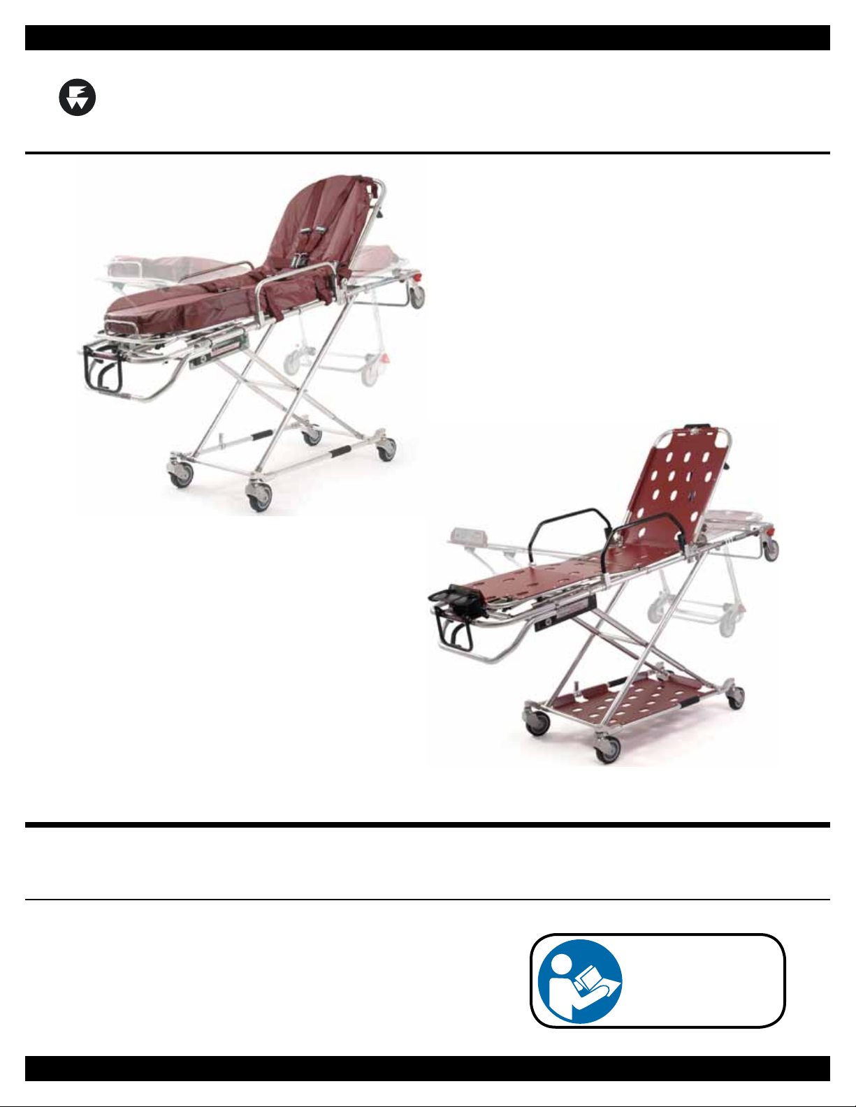
Model 35A Series Mobile Transporter
35A, 35A-ST, 35A+, 35A+ST
February 2011 GLO
Pub. No. 234-3451-01
™
Read this Manual
and Retain for
Future Reference
Page 2
Ferno Technical Support
Customer service and product support are important aspects of each
Ferno product. Please have the product serial number available
when calling, and include it in all written communications. For
technical support questions:
Telephone (Toll-free) 1.800.733.3766 ext. 1010
Telephone 1.937.382.1451 ext. 1010
Email quality.products@ferno.com
Ferno Customer Relations
For ordering assistance or general information:
CANADA AND THE U.S.A.
Telephone (Toll-free) 1.877.733.0911
Telephone 1.937.382.1451
Fax (Toll-free) 1.888.388.1349
Fax 1.937.382.1191
Internet www.ferno.com
ALL OTHER LOCATIONS
For assistance or information, please contact your Ferno
distributor. If you do not have a Ferno distributor, please contact
Ferno Customer Relations:
Ferno-Washington, Inc.
70 Weil Way
Wilmington, Ohio 45177-9371, U.S.A.
Telephone +1.937.382.1451
Fax +1.937.382.6569
Internet www.ferno.com
EUROPEAN REPRESENTATIVE
Ferno (UK) Limited
Stubs Beck Lane, Cleckheaton
West Yorkshire BD19 4TZ, United Kingdom
Telephone +44 (0) 1274 851999
Fax +44 (0) 1274 851111
Internet www.ferno.co.uk
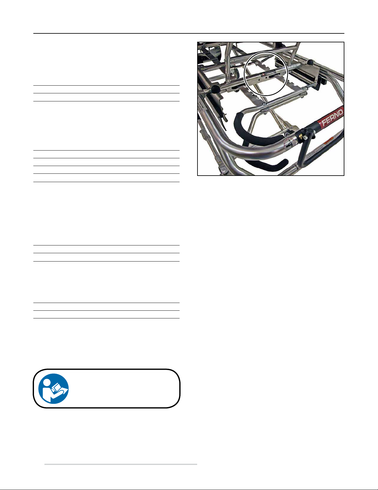
Model 35A Series
Serial Number _________________________
Location (All Models): Crosstube under shock frame
Disclaimer
This manual contains general instructions for the use, operation
and care of this product. The instructions are not all-inclusive. Safe
and proper use of this product is solely at the discretion of the
user. Safety information is included as a service to the user. All
other safety measures taken by the user should be within and under
consideration of applicable regulations. It is recommended that
training on the proper use of this product be provided before using
this product in an actual situation.
Retain this manual for future reference. Include it with the product
in the event of transfer to new users. Additional free copies are
available upon request from Customer Relations.
Proprietary Notice
The information disclosed in this manual is the property of FernoWashington, Inc., Wilmington, Ohio, USA. Ferno-Washington, Inc.
reserves all patent rights, proprietary design rights, manufacturing
rights, reproduction use rights, and sales use rights thereto, and
to any article disclosed therein except to the extent those rights
are expressly granted to others or where not applicable to vendor
proprietary parts.
Limited Warranty Statement
USERS’ MANUAL
To request additional free users’ manuals,
contact Ferno Customer Relations, your
Ferno distributor, or visit www.ferno.com.
© Copyright Ferno-Washington, Inc. All Rights Reserved.
2
The products sold by Ferno are covered by a limited warranty,
which is printed on all Ferno invoices. The complete terms and
conditions of the limited warranty, and the limitations of liability
and disclaimers, are also available upon request by calling Ferno at
1.800.733.3766 or 1.937.382.1451.
© Ferno-Washington, Inc 234-3451-01 February 2011
Page 3

Model 35A Series
TABLE OF CONTENTS
Section Page Section Page
Ferno Customer Relations _________________________2
Ferno Technical Support __________________________2
1 - Safety Information ______________________________4
1.1 Warning __________________________________4
1.2 Important _________________________________4
1.3 Bloodborne Disease Notice ___________________4
1.4 Cot and Fastener Compatibility ________________4
1.5 Symbol Glossary ___________________________4
1.6 Safety and Instruction Labels __________________5
2 - Operator Skills and Training _____________________6
2.1 Skills _____________________________________6
2.2 Training __________________________________6
2.3 Height and Strength Considerations _____________6
3 - About the Cot __________________________________7
3.1 Description ________________________________7
3.2 GeneralSpecications _______________________8
3.3 Cot Positions ______________________________8
4 - Setup and Installation ___________________________9
4.1 Ambulance Information ______________________9
4.2 Restraints and Accessories ____________________9
4.3 Fastener Compatibility _______________________9
4.4 Install the Safety Hook ______________________10
5 - Using the Features _____________________________12
5.1 Lift-First Control Handles ___________________12
5.2 Ergonomic Lifting Positions _________________13
5.3 Fastener Release Controls ___________________13
5.4 Two-Position Drop Frame ___________________14
5.5 Backrest _________________________________14
5.6 Shock Frame ______________________________15
5.7 Sidearms _________________________________15
5.8 Lead Handle ______________________________16
5.9 Wheel Locks (Optional) _____________________16
5.10 Oxygen Cylinder Holder
(Models 35A+, 35A+ST Only) _______________17
5.11 Storage Tray (Models 35A+, 35A+ST Only) _____17
6 - Using the Cot _________________________________18
6.1 Before Placing the Cot in Service _____________18
6.2 General Guidelines for Use __________________18
6.3 Fully Engaging the Locking Mechanism ________18
6.4 Raising and Lowering the Cot ________________19
6.5 Transferring the Patient to the Cot _____________20
6.6 Rolling the Cot ____________________________21
6.7 Preparing to Load the Cot ___________________22
6.8 Loading the Cot ___________________________22
6.9 Unloading the Cot _________________________23
6.10 One Operator, Empty Cot ____________________24
6.11 Using Additional Help ______________________25
7 - Maintenance __________________________________26
7.1 Maintenance Schedule ______________________26
7.2 Disinfecting and Cleaning the Restraints ________26
7.3 Disinfecting and Cleaning the Mattress _________26
7.4 Disinfecting the Cot ________________________26
7.5 Cleaning the Cot ___________________________26
7.6 Waxing the Cot ____________________________27
7.7 Inspecting the Cot _________________________27
7.8 Lubricating the Cot ________________________28
8 - Accessories and Related Products ________________29
9 - Parts and Service ______________________________29
9.1 U.S.A. and Canada _________________________29
9.2 Worldwide _______________________________29
9.3 Selected Parts for Cots
Before Serial Number L-322137 ______________29
9.4 Parts for Cots
Serial Number L-322137 and Higher ___________30
Training Record _________________________________31
Maintenance Record ______________________________31
© Ferno-Washington, Inc 234-3451-01 February 2011
3
Page 4
Safety Information
Model 35A Series
1 SAFETY INFORMATION
1.1 Warning
Warning notices indicate a potentially hazardous situation
which, if not avoided, could result in injury or death.
WARNING
Untrained operators can cause injury or be injured.
Permit only trained personnel to operate the cot.
Improper use of the cot can cause injury. Use the cot only
for the purpose described in this manual.
Attaching improper items to the cot can cause injury. Use
only Ferno-approved items on the cot.
Failure to use the safety hook can cause injury. Install and
use the safety hook as described in this manual.
Improper operation can cause injury. Operate the cot
only as described in this manual.
An unattended patient can be injured. Stay with the
patient at all times.
An unrestrained patient can fall o the cot and be injured.
Use restraints to secure the patient on the cot.
Rolling the cot sideways or in a loading position can cause
the cot to tip and injure the patient or operators. Roll the
cot only in a level (rolling) position and with the head-end
or foot-end rst.
False locking can cause injury. After changing positions,
lift the cot until all the wheels are o the ground. This
allows the lock to engage if it has not already done so.
Helpers can cause injury. Maintain control of the cot,
operate the controls, and direct all helpers.
Helpers can be injured. Show helpers where to grasp the
cot to avoid pinch points.
Improper maintenance can cause injury. Maintain the cot
only as described in this manual.
Improper parts and service can cause injury. Use only
Ferno parts and Ferno-approved service on the cot.
Modifying the cot can cause injury and damage. Use the
cot only as designed by Ferno.
1.3 Bloodborne Disease Notice
To reduce the risk of exposure to bloodborne diseases such as
HIV-1 and hepatitis when using the cot, follow the disinfecting
and cleaning instructions in this manual.
1.4 Cot and Fastener Compatibility
Combining different manufacturers’ products into a “mixedcomponent” cot/cot fastener system can increase the user’s risk
of injury and damage.
Ferno-Washington, Inc. strongly recommends that only
Ferno-manufactured cots be used in Ferno-manufactured cot
fasteners, and that only Ferno-manufactured cot fasteners be
used for securing Ferno-manufactured cots in ambulances.
ANY COMBINATION OF A FERNO COT OR COT
FASTENER WITH A NON-FERNO COT OR COT
FASTENER IS MISUSE OF THE FERNO PRODUCT.
Responsibility for the outcome of known, intentional misuse
rests squarely on the misuser.
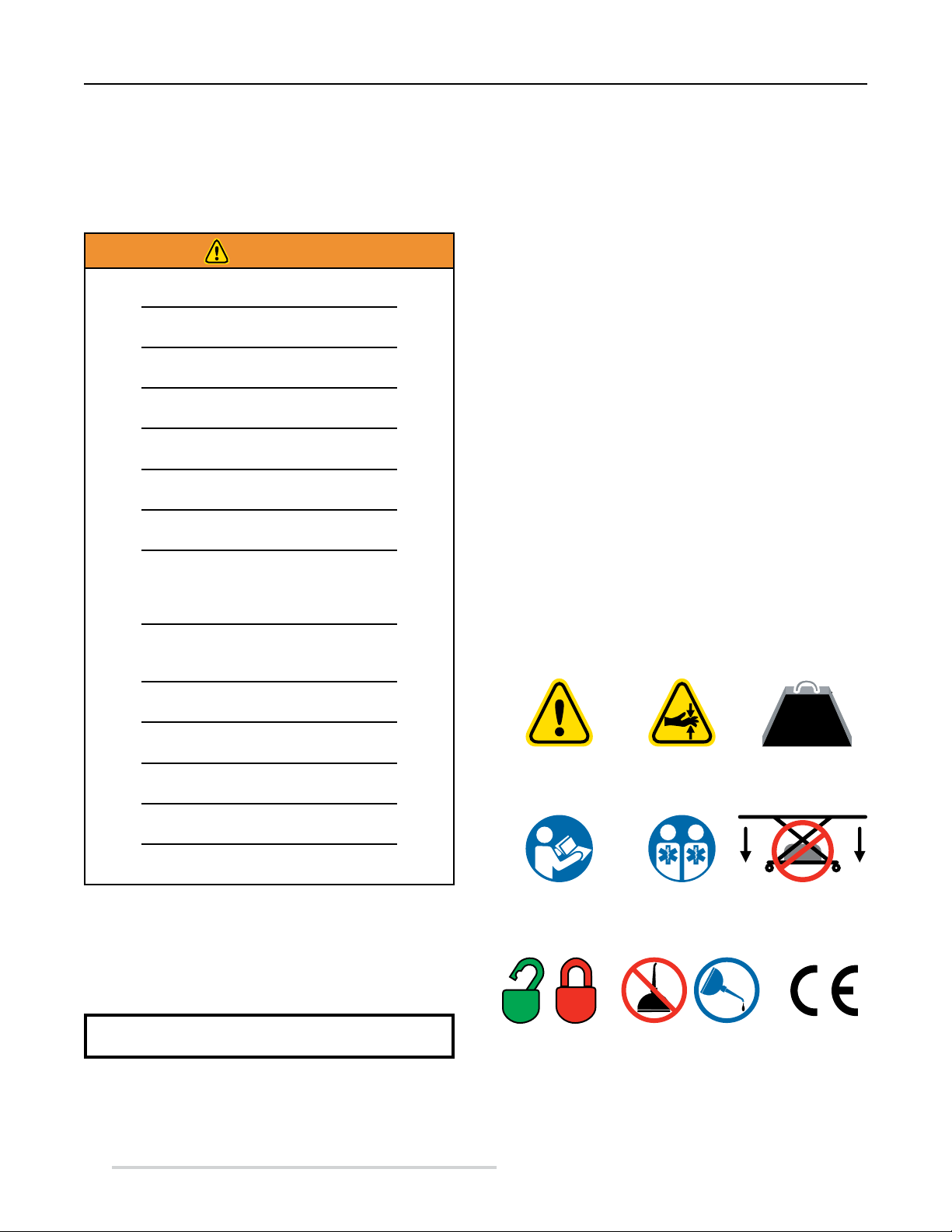
1.5 Symbol Glossary
Thesymbolsdenedbelowareusedonthecotandinthisusers’
manual. Ferno uses symbols recognized by the International
Standards Organization (ISO), American National Standards
Institute (ANSI) and the emergency medical services industry.
500 lb
227 kg
General Warning
of Potential Injury
Read the
Users’ Manual
Pinch Point:
Keep Hands Clear
2
Cot Operation Requires
Two Trained Operators
Load Limit
Do Not Fold Cot
With Items On Tray
1.2 Important
Important notices emphasize important usage or maintenance
information.
Important
4
Unlocked
Locked Product meets
© Ferno-Washington, Inc 234-3451-01 February 2011
Do Not
Lubricate
Lubricate
European Union
Standards
Page 5
Model 35A Series
Safety Information
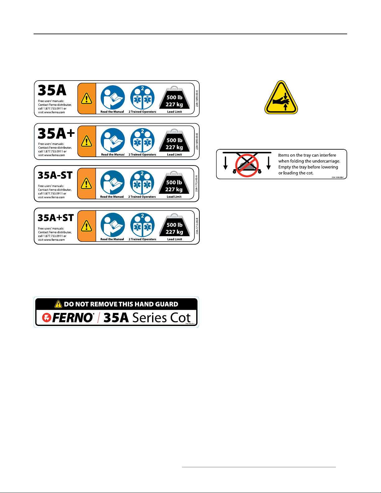
1.6 Safety and Instruction Labels
Safety and instruction labels place important information from the users’ manual on the cot. Read and follow label instructions. Replace
worn or damaged labels immediately. New labels are available from EMSAR (page 29) or from your Ferno distributor (page 2).
Pinch Point Label (Qty. 4 or 6)
Keep hands clear of these areas
Tray Label (Qty. 2)
On cots equipped with a lower storage tray, this label
reminds operators to empty the tray before lowering or
loading the cot.
General Information Label (Qty. 1)
is label identies the cot and warns the user to read the users’
manual, operate the cot with two trained operators, and to observe the
cot load limit.
Hand Guard Label (Qty. 2)
Removing the guard can expose operators or helpers to injury. Do not
remove the guard.
© Ferno-Washington, Inc 234-3451-01 February 2011
5
Page 6
Operator Skills and Training
2 OPERATOR SKILLS AND TRAINING
Model 35A Series
2.1 Skills
Operators using the cot need:
● a working knowledge of emergency patient-handling
procedures.
● the ability to assist the patient.
2.3 Height and Strength Considerations
2.2 Training
Operator trainees need to:
● read and understand this manual.
● be trained on the use of the cot.
● practice with the cot before using it with a patient.
● record their training information. A sample training
record sheet is provided on page 31.
WARNING
Untrained operators can cause injury or be injured.
Permit only trained personnel to operate the cot.
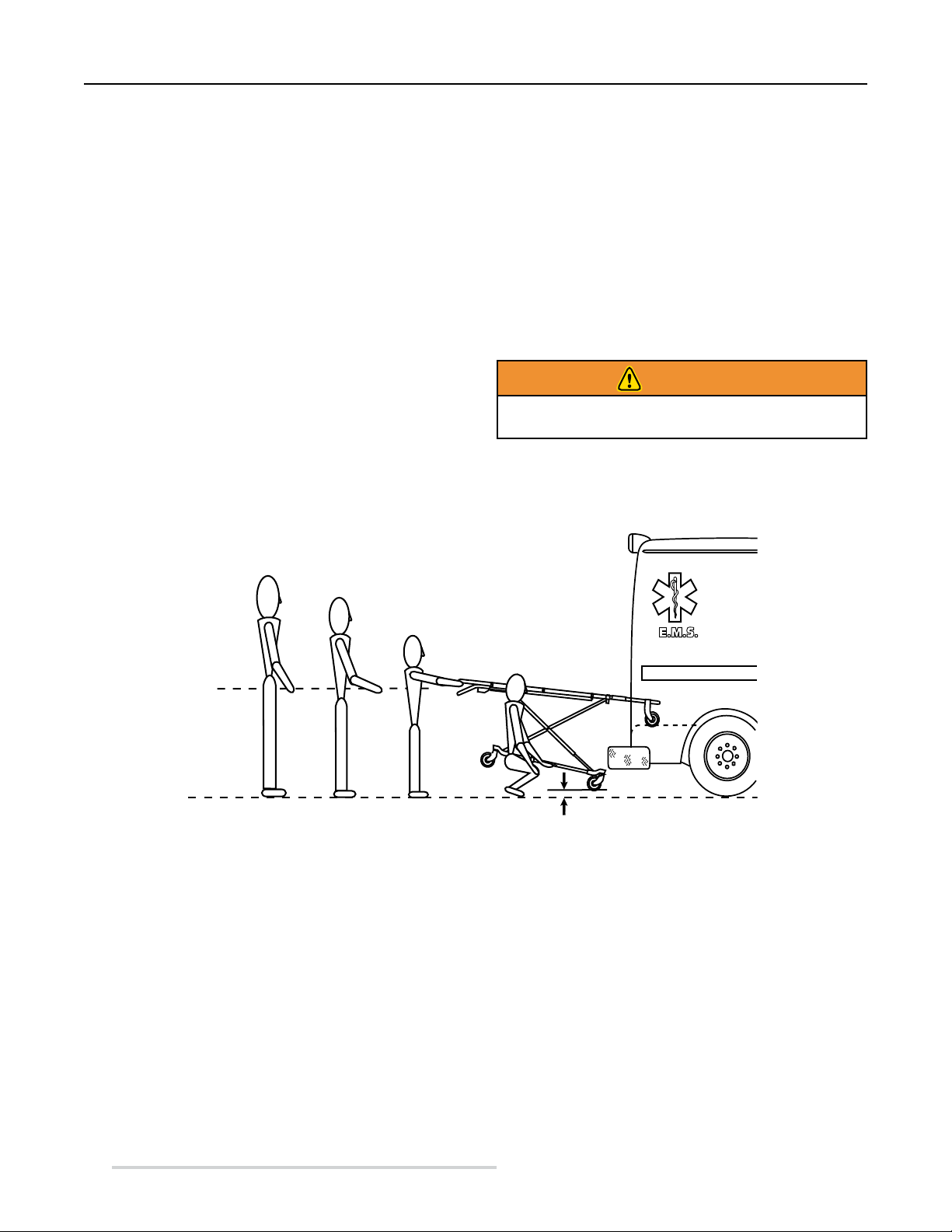
When unloading the cot, the foot-end operator must lift and
hold the weight of the cot, patient and equipment high enough
for the wheels to remain off the ground until the undercarriage
legs completely unfold and lock into place.
Supporting this weight requires greater strength from short
operators than from tall operators because short operators must
raise their arms higher in relation to their shoulders.
6
Be aware that if the ambulance is parked on an uneven surface,
the foot-end operator (and any helpers) may need to lift the cot
higher than normal to allow the legs to unfold completely and
lock.
Note: Use additional help as needed to lift the weight of the cot,
patient and equipment (see Using Additional Help, page 25).
© Ferno-Washington, Inc 234-3451-01 February 2011
Page 7

Model 35A Series
About the Cot
3 ABOUT THE COT
3.1 Description
The Ferno® Model 35A Series Mobile Transporter™ (called the
“cot” in this manual) is an emergency patient-handling device
designed to transport a patient in a ground-based ambulance.
The cot is for professional use by a minimum of two trained
operators. It is designed for roll-in loading to help reduce the
risk of back injury to medical service personnel.
The standard term “cot” is used in this manual when features
are the same among all models. When features differ, the
specicmodelnameisused.
COT FEATURES ALL COTS
● Clear-anodized handling surfaces keep hands and clothes
clean
● Eight height positions
● Twoloadingpositionsforvehicleoors28 inchesto32
inches (711-810 mm)
● Pneumatic backrest
● Two-position drop frame
● Two-position shock frame
● Swing-down sidearms
● Lead handle
● Four 5"x1.25" (127x32 mm) transport wheels and two
5"x1" (127x25 mm) loading wheels
● Users’ manual included
● The following are included or available for purchase
separately, based on the terms of your purchase order.
(For more information, contact your distributor or Ferno
Customer Relations, page 2)
○ Set of three restraints
○ Mattress
WARNING
Improper use of the cot can cause injury. Use the cot
only for the purpose described in this manual.
U.S.A. NOTICE
The cot is for use with ambulances that meet the requirements
of the “Star of Life” certication via Federal Ambulance
SpecicationKKK-A-1822.Forinformation,contact:
FederalSupplyServices,SpecicationsSection
Suite 8100
470 E. L’Enfant Plaza, SW
Washington, DC 20407
MODELSPECIFIC COT FEATURES
Cot Name Bed Surface
Compatible with
Ferno® Cot Fastener
Oxygen Cylinder
Holder
Storage Tray
Wheel Locks
(2 Wheels)
35A Aluminum Tubes 175 (Antler/Rail) Accessory Accessory Option
35A-ST Aluminum Tubes Stat Trac® Accessory Accessory Option
35A+ Aluminum Panels 175 (Antler/Rail) Standard Standard Option
35A+ST Aluminum Panels Stat Trac® Standard Standard Option
COT FASTENER NOTES
● Cots compatible with the Model 175 antler/rail fastener
are constructed with an integrated fastener post, fastener
release levers, and a safety bar as standard cot features. A
user-installed safety hook is shipped with the cot (Model
35A and Model 35A+).
© Ferno-Washington, Inc 234-3451-01 February 2011
● Cots compatible with the Stat Trac
constructed with two fastener loading posts and a fastener
release handle as standard cot features (Model 35A-ST
and Model 35A+ST).
®
fastener are
7
Page 8
About the Cot
Model 35A Series
3.2 General Specications
Most general specications below are rounded to the nearest
whole number. Metric conversions are calculated before rounding
the Imperial measurements. For more information, contact Ferno
Customer Relations (page 2) or your Ferno distributor.
Fernoreservestherighttochangespecicationswithoutnotice.
Construction Tubular aluminum
Wheels
Diameter 5 in./127 mm
Width 1.25 in./32 mm
Wheel Bearings Sealed/greaseless
Bed Surface (35A, 35A-ST) Aluminum tubes
Bed Surface (35A+, 35A+ST) Aluminum panels
1
Height
Bed Position 8 35 in./883 mm
Loading Position 2 32 in./810 mm
Bed Position 7 33 in./834 mm
Loading Position 1 28 in./711 mm
Bed Position 6 30 in./772 mm
Bed Position 5 28 in./699 mm
Bed Position 4 24 in./616 mm
Bed Position 3 20 in./521 mm
Bed Position 2 16 in./413 mm
Bed Position 1 (folded) 10 in./257 mm
Length
Maximum 79 in./2007 mm
Minimum 61 in./1549 mm
Width (Overall) 24 in./610 mm
Weight2
35A 74 lb/34 kg
35A-ST 78 lb/35 kg
35A+ 84 lb/38 kg
35A+ST 88 lb/40 kg
Strength to Weight Ratio
35A 6.76 SWR
35A-ST 6.41 SWR
35A+ 5.95 SWR
35A+ST 5.68 SWR
Load Limit 500 lb/227 kg
All Ferno® mattresses for emergency medical service use
Note:
are heat-sealed.
1
Height measurements are as follows: Loading Position is the
distance from the ground to the bottom of the loading wheel. Bed
Position is the distance from the ground to the patient surface,
measured at the casting in the center of the bed surface.
2
Weight is without mattress, restraints and optional features.
3
Strength to Weight Ratio is the load limit of the cot divided by the
cot’s weight.
3
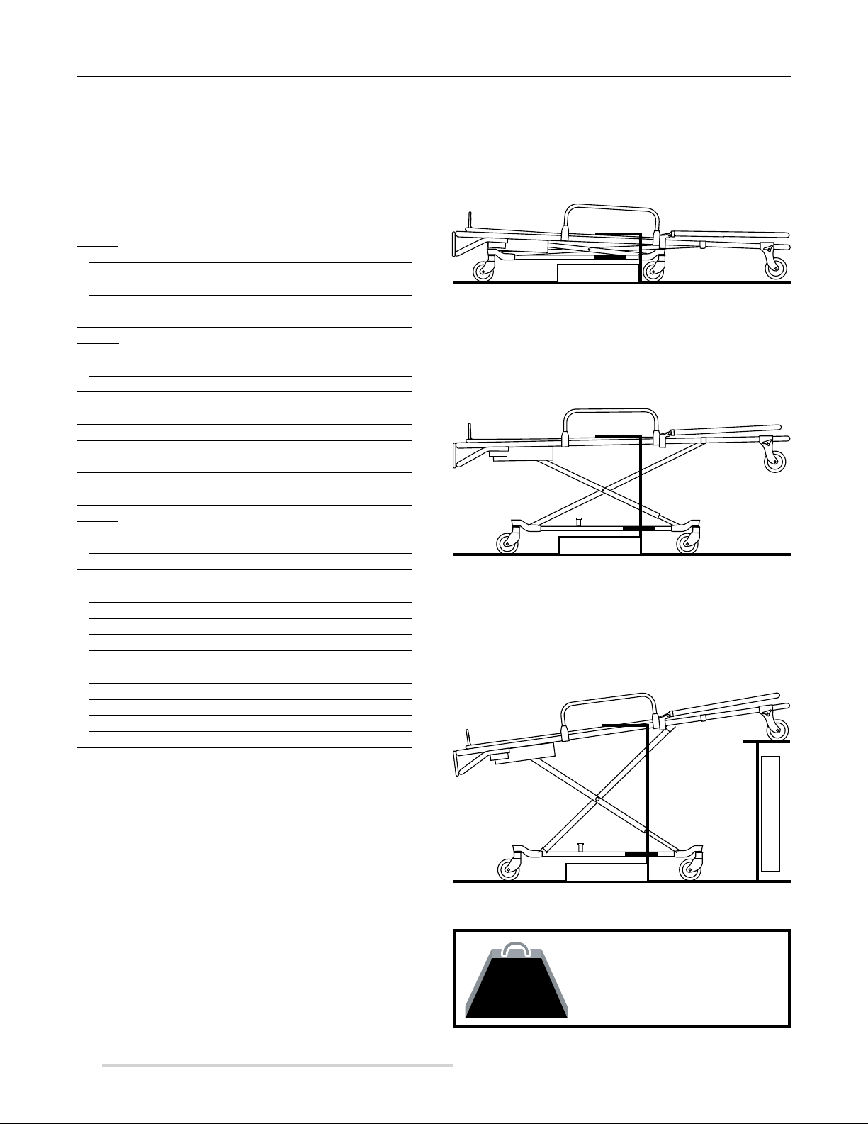
3.3 Cot Positions
FOLDED POSITION
Use the folded position to transfer the patient, secure the cot
inside an ambulance, or to store the cot.
Bed Position
ROLLING/TRANSFER POSITION 5
Use a level position to roll the cot and for transferring the
patient to or from the cot.
Bed Position
LOADING POSITION 2
The loading positions are for use only when loading the cot
into, or unloading the cot from, an ambulance. Use the lowest
loading position that allows the cot to roll into the ambulance.
Loading Position
Bed Position
Load Limit
500 lb
227 kg
8
© Ferno-Washington, Inc 234-3451-01 February 2011
Inspect the cot if the load limit has
been exceeded (See Inspecting the
Cot, page 27).
Page 9
Model 35A Series
Setup and Installation
4 SETUP AND INSTALLATION
4.1 Ambulance Information
The ambulance bumper extension should not exceed 14 inches
(356mm).Thepatientcompartmentshouldhavea leveloor
large enough for the folded cot, and a Ferno® cot fastener
installed (not included). See Cot and Fastener Compatibility,
page 4.
4.2 Restraints and Accessories
Before placing the cot in service, place the mattress on the cot
bed and assign appropriate personnel to install the restraints and
any accessories shipped with the cot. Follow the instructions
in the restraint and accessory users’ manuals supplied with the
products.
Keep all restraint and accessory users’ manuals with this
manual for future reference.
For additional, free manuals, contact Ferno Customer Relations
or your Ferno distributor (page 2).
WARNING
Attaching improper items to the cot can cause
injury. Use only Ferno-approved items on the cot.
Important
Loose items and debris on the patient compartment
floor can interfere with the operation of the cot
with the fastener. Keep the patient compartment
floor clear.
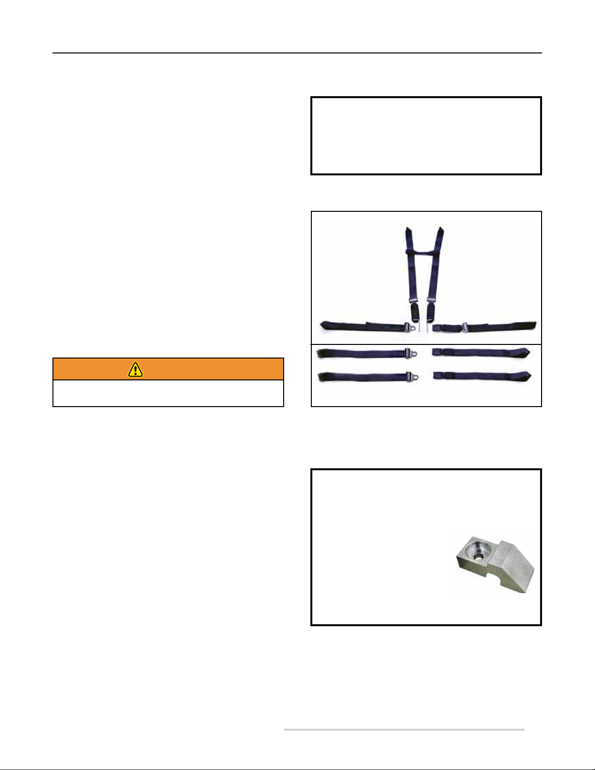
Harness Restraint (1)
Two-Piece Restraint (2)
4.3 Fastener Compatibility
Read the cot fastener users’ manual for instructions on using
the fastener (see Cot and Fastener Compatibility, page 4).
ANTLERANDRAIL FASTENER
The Models 35A and 35A+ cots are compatible with all versions
of the Ferno® Model 175 antler-and-rail cot fasteners. The cot
fastener must be congured for use with the Ferno® Model
35 Series. See the fastener installation manual for complete
installation details.
Using the Model 175 cot fastener requires the installation of the
safety hook (included with the cot).
STAT TRAC® FASTENER
The Models 35A-ST and 35A+ST cots are compatible with all
versions of the Ferno® Model 185 Stat Trac® fastener. See the
fastener installation manual for complete installation details.
Figure 1 - Restraints (Set of Three)
Important
A “sloped” (or low-prole) mounting block (shown
here) must be used when the antler portion of the cot
fastener is removable (installed with large turn-knobs
for easy removal).
If your removable fastener
does not already have this
mounting block, contact Ferno
Customer Relations, page 2.
This block is not used with fasteners permanentlymounted to the oor with a large bolt.
© Ferno-Washington, Inc 234-3451-01 February 2011
9
Page 10

Setup and Installation
Model 35A Series
4.4 Install the Safety Hook
Note: If your ambulance service uses only the Stat Trac®
Fastening System, skip the rest of Section 4.
The safety hook (Figure 2) provided with the cot must be
installedontheambulanceoor.Thesafetyhookisusedwith
the Ferno
The safety hook catches the cot safety bar (Figure 3) to ensure
that the cot remains secure inside the ambulance while the
operators raise or lower the undercarriage during loading or
unloading.
Installing the safety hook requires the skills of a mechanic
familiar with ambulance construction.
Before installing the safety hook, consult the ambulance
manufacturer regarding:
● the location of wiring, oxygen or fuel lines, and other
● the ambulance warranty.
2 1/4-20 Socket-head cap screws
2 Flat washers
2 Lock washers
2 1/4-20 Nuts
● The socket-head cap screws must be long enough to pass
● The hardware should be of at least SAE Grade 5 or higher,
®
Model 175 Cot Fastener.
elementsundertheambulanceoor
HARDWARE REQUIRED NOT SUPPLIED
through the safety hook, patient compartment oor, both
washers, and still have at least two full threads extending
past the nut.
with UNC-2 threading (or equivalent), and a corrosionreisistant coating.
Hook
Front Edge
4-Inch Safety Hook (Standard)
Hook
Front Edge
2.5-Inch Safety Hook (Optional)
Figure 2 - Safety Hook (One Shipped with Cot)
WARNING
Failure to use the safety hook can cause injury.
Install and use the safety hook as described in this
manual.
Important
Before installing the safety hook, consult the
ambulance manufacturer about possible interference
with wiring and other elements under the ambulance
oor, and about the ambulance warranty.
10
Safety Bar
Safety Hook
Figure 3 - Engaging the Safety Hook
© Ferno-Washington, Inc 234-3451-01 February 2011
Page 11

Model 35A Series
PROPER SAFETY HOOK PLACEMENT
Position the safety hook as close to the rear of the ambulance as
possible, within the limits below:
● The bumper or extended folding bumper must not exceed
14 inches (356 mm).
● Position the safety hook with the hook facing the front of
the ambulance.
● Position the safety hook at least 11 inches (279 mm)
from both sides of the door frame (Figure 4) so the cot
safety bar will engage the hook when the cot is loaded
or unloaded.
● Position the safety hook no more than
19-7/8 inches (505 mm) from the front edge of the hook
to the rear of the ambulance, including the bumper and
folding bumper step in the extended (open) position.
Important
If the safety hook is installed too far inside the
ambulance, you will not be able to properly fold or
unfold the cot undercarriage when it is secured by the
hook. Measure and install the safety hook as instructed
in this manual.
Setup and Installation
Maximum
11" (279 mm)
Figure 4 - Safety Hook Placement
Socket-Head Cap Screw
Ambulance Rear Ambulance Front
19-7/8" (505 mm)
11" (279 mm)
Hook
INSTALLING THE SAFETY HOOK
1. Markthepositionofthesafetyhookontheoor.
2. Drill holes for the screws and attach the safety hook to
theoor(Figure5).
3. To test the hook, load and unload the cot. Verify that
there is no interference with folding or unfolding the
legs.
Front Edge
Flat Washer
Lock Washer
Nut
Figure 5 - Installing the Safety Hook
© Ferno-Washington, Inc 234-3451-01 February 2011
11
Page 12

Using the Features
5 USING THE FEATURES
5.1 Lift-First Control Handles
● Purpose: An operator uses one of the Lift-First control handles
to disengage the locking mechanism and raise or lower the cot.
● Location: There are three Lift-First control handles: an upper and
a lower control handle at the cot foot end (Figure 6), and a side
control handle at the patient’s right side of the cot (Figure 7).
● Use: Any one of the control handles may be used to disengage
the undercarriage lock.
○ A “Lift-First” style control handle requires the operators
to lift the weight of the cot, patient and accessories off the
locking mechanism before pulling the control handle.
○ To lift the cot evenly, the two trained operators must stand
opposite one another. If using a foot-end control handle,
position the assisting operator at the cot head end. If using
the side control handle, position the assisting operator at the
opposite side of the cot.
○ Use the control handle that is best for the lifting situation.
For example, the lower control handle gives a short operator
better leverage for lifting.
○ After the position change, both operators continue to
support the weight of the cot, patient and accessories
while the operator releases the control handle to allow the
undercarriage to lock. Both operators verify that the cot has
locked at the new position before relaxing their grasp on the
main frame.
Model 35A Series
Figure 6 - Foot-end Control Handles
Using the Lift-First Control Handle
1. All Operators/Helpers: In a movement coordinated between
the operators and any helpers, lift the cot to take the weight
off the locking mechanism.
2. Control Operator: While continuing to hold the weight of
the cot, open the control-handle hand and pull the control
handle to unlock the cot’s locking mechanism.
3. All Operators/Helpers: Raise or lower the cot to the desired
height.
4. Control Operator: Release the control handle when the cot
is near the desired height.
5. All Operators/Helpers: Continue to raise or lower the cot
until the lock engages.
6. All Operators/Helpers: Before relaxing your grasp on the
cot main frame, verify that the cot has locked at the new
position.
Figure 7 - Side Control Handle
12
© Ferno-Washington, Inc 234-3451-01 February 2011
Page 13

Model 35A Series
5.2 Ergonomic Lifting Positions
● Purpose: Both operators choose the best position
for lifting and lowering the cot.
● Use: Always grasp the cot with both hands, using an
underhand (palms up) grip. For complete instructions,
see Raising and Lowering the Cot, page 19.
Foot-end Operator: Select either the upper or
lower lifting frame (Figure 8)
Head-end Operator:
○ Models 35A and 35A+ Only: Grasp the drop
frame or the safety bar (Figure 8)
○ Models 35A-ST, 35A+ST Only: Grasp the
drop frame (main frame)
5.3 Fastener Release Controls
● Purpose: The fastener release control lever
(Models 35A, 35A+) or fastener release control
handle (Models 35A-ST, 35A+ST) allows the cot
to be released from the cot fastener when unloading
the cot from an ambulance.
● Location: The lever or handle is located near the
cot loading wheels.
● Use: Before using the control lever or handle,
verify that the undercarriage is locked, then release
the cot from the fastener as follows:
○ Models 35A, 35A+: Release the cot from
the safety hook by turning the lever counterclockwise (Figure 9).
○ Models 35A-ST, 35A+ST: Release the cot
from the Stat Trac® safety stop by squeezing
the release handle (Figure 10).
Figure 8 - Short Operators Grasping the
Lower Lift Frame and Safety Bar
Figure 9 - Release Lever
(Model 175 Fastener)
Using the Features
Figure 10 - Release Handle
(Stat Trac® Fastener)
© Ferno-Washington, Inc 234-3451-01 February 2011
13
Page 14

Using the Features
5.4 Two-Position Drop Frame
● Purpose: In the extended position, the two-position drop
frame (Figure 11) is used for raising, lowering, loading,
and unloading the cot. In the lowered position, it is used
to shorten the cot where space is limited, such as in an
elevator or narrow hallway. The frame is unlocked in the
lowered position and is not usable for lifting.
● Use: To lower the drop frame:
1. Place the cot in Position 5 or Position 6.
2. Unfasten or loosen the harness restraint and raise the
backrest.
3. Grasp the hinge sleeves on the drop frame and slide
them toward the head end of the cot to expose the
hinges (Figure 11).
4. Push the drop frame down.
5. Fasten and/or adjust the harness restraint.
To extend the drop frame, raise the frame until the hinge sleeves
automatically snap over and lock the hinges.
Model 35A Series
Pull Hinge Sleeves Toward
End of Drop Frame
Figure 11 - Lowering the Drop Frame
5.5 Backrest
● Purpose: The backrest allows the patient’s torso to
be elevated for comfort or for medical necessity. The
backrest can be adjusted between 0° and 75°.
● Before Use:
○ Loosen or unbuckle the harness restraint.
○ Support the weight of the backrest and patient.
● Use: Press the red control handle toward the backrest frame
to unlock the backrest (Figure 12), then raise or lower the
backrest to the desired position. Release the control handle
to lock the backrest at the new position.
○ The backrest is under pressure to ease raising
and lowering. When a heavy patient is on the cot,
support the patient’s weight before adjusting the
backrest. When a light patient is on the cot, control
the upward movement of the backrest so it does not
move too quickly.
● After Use: Buckle and/or adjust the harness restraint.
Control
Handle
Figure 12 - Adjusting the Backrest
14
© Ferno-Washington, Inc 234-3451-01 February 2011
Page 15

Model 35A Series Using the Features
5.6 Shock Frame
● Purpose: The shock frame allows the operator to elevate
the patient’s legs to treat shock or for patient comfort.
● Use:
○ Before Use: Loosen or unbuckle the leg restraint.
○ To raise, stand at the foot end of the cot. Use both
hands to lift the shock frame until it locks in the
raised position.
○ To lower, stand at the foot end of the cot. Lift the
shock frame slightly to support the weight, then
press the two thumb levers (Figure 13) and lower
the shock frame.
○ After Use: Buckle and/or adjust the leg restraint.
5.7 Sidearms
● Purpose: Sidearms provide patient security and comfort.
Keep the sidearms raised except when transferring a
patient to or from the cot.
● Use:
○ To lower, squeeze the sidearm release handle (Figure
14) and lower the sidearm.
○ To raise, lift the sidearm until it locks. You do not
need to use the release handle.
1 - Lift Slightly
2 - Press Thumb
Tabs
Figure 13 - Lowering the Shock Frame
Figure 14 -
Sidearm Release
Handle
Important
Do not use the sidearms to lift the cot. Sidearms are
not designed for lifting. Lift the cot only by grasping
the main frame.
© Ferno-Washington, Inc 234-3451-01 February 2011
15
Page 16

Using the Features
5.8 Lead Handle
● Purpose: The lead handle allows the foot-end operator to
pull the cot when it is in a rolling position.
● Use: Raise the lead handle for use; lower it when not in
use (Figure 15).
○ Use the lead handle only when the cot is on a smooth,
level surface. When rolling the cot on an incline or
rough terrain, grasp the main frame of the cot with
both hands.
Model 35A Series
Figure 15 - Lead Handle
5.9 Wheel Locks (Optional)
● Purpose: The wheel locks help keep the cot stationary
during patient transfer and certain medical procedures.
When engaged, the wheel lock stops wheel rotation.
● Location: On equipped cots, the wheel locks are located
at opposite corners of the cot where they are accessible to
the operator’s right foot.
● Use (Figure 16):
○ To engage: The trailing end of the lock lever is
marked with the word “ON”; press this end of the
lever to engage the lock.
○ To disengage: The shank-end of the lever is marked
with the word “OFF”. Press this end of the lever to
disengage the wheel lock.
○ Wheel locks are NOT brakes. Engage the wheel
locks only when the cot is stationary. Stay with the
cot and maintain control of it at all times. Do not
leave the patient unattended.
Wheel Shank
Trailing End:
“ON” or
Engage
Shank End:
“OFF” or
Disengage
Figure 16 - Wheel With Wheel Lock
16
© Ferno-Washington, Inc 234-3451-01 February 2011
Page 17

Model 35A Series
5.10 Oxygen Cylinder Holder
(Models 35A+, 35A+ST Only)
● Purpose: The oxygen cylinder holder secures a “D”-
size or “Jumbo D”-size portable oxygen cylinder (up to
5.3" (135 mm) diameter by 18.75" (476 mm) length. It
is also compatible with Spiracle Technology’s “DD-Lite”
oxygen cylinder.
● Location: On equipped cots, the oxygen cylinder holder
is attached to the foot end of the shock frame (Figure 17).
● Use:
1. Unfasten the straps and center the cylinder on the
holder.
2. Wrap the straps around the cylinder and thread the
straps through the D-rings.
3. Cinch the straps tight, then press the hook-and-loop
fastener straps together (Figure 17).
Using the Features
Figure 17 - Oxygen Cylinder Holder
5.11 Storage Tray
(Models 35A+, 35A+ST Only)
● Purpose: The storage tray can hold items while the cot
is being rolled. Remove items before lowering or folding
the cot and before loading the cot into an ambulance.
Include the weight of items placed on the tray as part of
the total load on the cot.
● Location: On equipped cots, the tray is located between
the four transport wheels inside the cot undercarriage
(Figure 18).
Important
Items on the tray can interfere with folding the
undercarriage. Empty the tray before lowering, folding,
or loading the cot.
Figure 18 - Storage Tray
© Ferno-Washington, Inc 234-3451-01 February 2011
17
Page 18

Using the Cot
Model 35A Series
6 USING THE COT
6.1 Before Placing the Cot in Service
● Personnel who will work with the cot need to read this manual.
● Set up the cot, following the instructions in Setup and Installation, pages 9-11.
● Conrmthatthecotoperatesproperly.SeeInspecting the Cot, page 27.
● The vehicle must have a Ferno
®
cot fastener system installed.
2
500 lb
227 kg
Read the Users’
Manuals
Operation Requires
Two Trained Operators
Load Limit
6.2 General Guidelines for Use
● Medical advice is beyond the parameters of this manual.
● It is the users’ responsibility to ensure safe practices for the patient and themselves.
● A minimum of two trained operators is required.
● Follow standard emergency patient-handling procedures when operating the cot.
● Operators work together and maintain control of the cot at all times.
● Operators communicate with one another and use coordinated movements to
operate the cot.
● Lift only the weight you can safely handle. Use additional help when working
with heavy loads (patient and equipment). For placement of helpers, see Using
Additional Help, page 25.
● Stay with the patient at all times.
● Always use patient restraints to secure the patient on the cot.
WARNING
Improper operation can cause
injury. Operate the cot only as
described in this manual.
WARNING
An unattended patient can be
injured. Stay with the patient
at all times.
WARNING
An unrestrained patient can
fall o the cot and be injured.
Use restraints to secure the
patient on the cot.
WARNING
Rolling the cot sideways or in
a loading position can cause
the cot to tip and injure the
patient or operators. Roll the
cot only in a level (rolling)
position and with the headend or foot-end rst.
6.3 Fully Engaging the Locking Mechanism
False locking is a condition in which the locking mechanism does not fully engage when
a control handle is released. This can occur after changing cot positions if the locking pin
rests exactly on the tip of a ratchet bar tooth, and can allow the cot to lower to the next
locking position when moved.
To ensure the locking mechanism fully engages after changing positions, lift the cot until
all the wheels are off the ground. This allows the lock to fully engage if it has not already
done so.
18
© Ferno-Washington, Inc 234-3451-01 February 2011
WARNING
False locking can cause injury.
After changing positions, lift
the cot until all the wheels
are o the ground. This allows
the lock to engage if it has not
already done so.
Page 19

Model 35A Series
6.4 Raising and Lowering the Cot
Changing cot positions with a patient on the cot requires a
minimum of two trained operators working together.
PREPARING TO RAISE OR LOWER THE COT
1. Both Operators: If the cot is equipped with a storage
tray, empty the tray before lowering or folding the cot.
2. Assisting Operator: Raise the drop frame to the extended
position if needed.
3. Both Operators: Stand at opposite ends or sides of the
cot (Figure 19 or Figure 20).
4. Both Operators: Select the lifting position that
provides the best leverage. Use an underhand grip to
grasp the cot frame (or safety bar, see Ergonomic Lifting
Positions, page 13).
5. Foot-End or Side-Control Operator: Position your
hand to use the control handle.
Important
Extend the drop frame before adjusting the height of
the cot.
Using the Cot
Figure 19 - Raising or Lowering the Cot
Important
Operators should expect and be prepared to control
the normal downward movement of the cot which
occurs when a control handle is squeezed.
RAISING OR LOWERING THE COT
1. Both Operators: Lift the cot slightly to take the weight
off the locking mechanism.
2. Both Operators: As the control operator squeezes and
holds the control handle, both operators raise or lower
thecot.Ifthecontrolhandleisdifculttosqueeze,both
operators lift the cot a little higher to free the locking
mechanism.
3. Control Operator: Release the control handle when the
cot is near the desired height.
4. Both Operators: Together, lift the cot until all four
transport wheels are off the ground. This ensures the
undercarriage lock engages if it has not already done so.
5. Both Operators:Setthecotontotheoororground.Do
not release your grasp until you are sure the undercarriage
is locked at the new position.
Figure 20 - Raising or Lowering the Cot
© Ferno-Washington, Inc 234-3451-01 February 2011
19
Page 20

Two-Stage Raising or Lowering
To maintain proper lifting techniques, the operators may choose
to adjust the cot height in two stages (Figure 21). To do this:
1. Use one set of lifting positions to raise or lower the cot
partway.
2. Stop at a comfortable position and verify that the
undercarriage is locked.
3. Adjust your hands to new lifting positions:
○ Assisting Operator: Move your hands from the drop
frame to the safety bar (if equipped) or vice-versa.
○ Control Operator: Move your hands from the main
frame to the lower lift frame or vice-versa.
4. Raiseorlowerthecottothedesirednalposition.
Model 35A SeriesUsing the Cot
Figure 21 - Raise or Lower the Cot Partway,
Then Adjust Your Grasp and Continue
6.5 Transferring the Patient to the Cot
To transfer a patient onto the cot:
1. Unfasten the restraints and arrange the straps so they will
not interfere with transferring the patient onto the cot.
2. Place the cot beside the patient and adjust it to the
patient’s level.
3. Engage the wheel locks (if equipped) and lower the
sidearms.
4. Transfer the patient onto the cot using approved EMS
procedures and following your local protocols.
5. Raise the sidearms. Adjust the backrest and shock frame
as needed.
6. Fasten and adjust the patient restraints (Figure 22).
7. Disengage the wheel locks if needed.
8. Before moving the cot or changing its position, make
sure sheets and other articles will not interfere with cot
operation.
Important
Sheets or other articles that are placed, or nd their way,
beneath the metal bed of the cot can become caught in
the ratchet mechanism and cause it to malfunction. Take
care to tuck sheets between the mattress and the metal
bed of the cot. Keep other articles above the mattress.
Figure 22 - Securing the Patient
20
© Ferno-Washington, Inc 234-3451-01 February 2011
Page 21

Model 35A Series Using the Cot
6.6 Rolling the Cot
GENERAL GUIDELINES
● Rolling the cot with a patient on the cot requires a
minimum of two trained operators working together
and maintaining control of the cot at all times.
● Rolling the cot in a loading position can increase the
chance for the cot to tip. Always use a rolling position to
roll the cot (See Cot Positions, page 8).
● Roll the cot on smooth, unobstructed surfaces whenever
possible.
● To cross a low obstacle such as a door sill, lift the cot
slightly to take the weight off the wheels so the wheels
roll smoothly over the obstacle.
● Lift and carry the cot over a high obstacle such as a curb.
Do not apply downward force on one end of the cot in
order to raise the other end of the cot over the obstacle.
● Do not roll the cot sideways. Rolling a cot sideways can
increase the chance for the cot to tip and injure the patient
and/or operators.
● Use additional help as needed to safely control the weight
of the patient and cot (see Using Additional Help, page 25).
● When rolling over rough terrain, the operators (and
helpers) should grasp the cot with both hands.
● Side helpers may need to walk sideways under some
circumstances. Follow local protocols.
WARNING
Rolling the cot sideways or in a loading position
can cause the cot to tip and injure the patient
or operators. Roll the cot only in a level (rolling)
position and with the head-end or foot-end rst.
Important
Roll the cot downhill foot-end rst. If it is not medically
appropriate to do this, roll the cot head-end rst, but
do the following:
To maintain cot balance while rolling the cot downhill
head-end rst, the Assisting Operator must exert
upward force on the drop frame.
ROLLING THE COT
1. Securely fasten the restraints around the patient.
2. Both Operators: Place the cot in a rolling position. See
Cot Positions, page 8.
3. Control Operator: Position yourself at the foot end of
the cot, grasp the main frame, and pull or push the cot.
Or,ifrollingthecotonasmooth,atsurface,unfoldthe
lead handle and pull the cot (Figure 23).
4. Assisting Operator: Position yourself at either the head-
end of the cot (grasping the drop frame) or at the side of
the cot near the patient’s torso (grasping the main frame,
Figure 23). Attend the patient and assist in rolling and
steering the cot.
Figure 23 - Rolling the Cot
© Ferno-Washington, Inc 234-3451-01 February 2011
21
Page 22

Using the Cot
6.7 Preparing to Load the Cot
1. Raise the ambulance folding bumper, if present.
2. Place the cot in a loading position (see Cot Positions,
page 8) and extend the drop frame.
3. If the cot is equipped with a lower tray, remove items
from the tray before loading the cot into the ambulance.
4. Roll the cot to the patient compartment door.
Use additional help as needed when working with heavy
Note:
loads (patient and equipment). See Using Additional Help, page 25.
Model 35A Series
Safety Hook
Important
If the ambulance is parked on an uneven surface, the
operators (and any helpers) may need to lift the cot
higher than normal to unlock the undercarriage.
Important
Loose items and debris on the patient compartment
oor can interfere with the operation of the cot with the
fastener. Keep the patient compartment oor clear.
6.8 Loading the Cot
Loading the cot with a patient on it requires a minimum of two
trained operators working together.
1. Both Operators: Roll the cot forward until both loading
wheelsareonthepatientcompartmentoorandeither:
○ the safety bar passes the safety hook (Figure 24).
OR
○ the head-end loading post passes the safety stop on
the Stat Trac fastener (Figure 25).
2. Control Operator: Lift the foot end of the cot until it is
levelwiththeambulanceoor(Figure26).
3. Control Operator: Squeeze and hold the undercarriage
control handle and tell the Assisting Operator to lift the
undercarriage.
4. Assisting Operator: Grasp the undercarriage grip
(Figure 26). When the Control Operator communicates
that he/she is ready, lift the undercarriage all the way up
and hold it in the folded position (Figure 27, page 23).
5. Control Operator: Let go of the undercarriage control
handle to lock the undercarriage in the folded position.
Push the cot into the ambulance.
6. Assisting Operator: Assist the Control Operator as
necessary. Release your grip on the undercarriage after
all of the cot’s wheels are inside the ambulance.
7. Either Operator: Secure the cot in the cot fastener.
Figure 24 - Safety Bar Past Safety Hook
Safety Stop
Figure 25 - Loading Post Past Safety Stop
Figure 26 - Loading and Unloading the Cot
22
© Ferno-Washington, Inc 234-3451-01 February 2011
Page 23

Model 35A Series
6.9 Unloading the Cot
Unloading the cot with a patient on it requires a minimum of two
trained operators working together.
1. Raise the folding bumper, if present.
2. Release the cot from the cot fastener.
3. Control Operator: Grasp the main frame or lift frame at the
foot end of the cot and squeeze the undercarriage control handle.
4. Control Operator: Keeping the foot end raised and level with
the ambulance oor (Figure 27),pull thecot slowlyfrom the
ambulance until the cot is stopped by either the safety hook or
the safety stop.
Assisting Operator: As the cot is pulled from the ambulance,
grasp the undercarriage hand grip and lower the undercarriage to
the ground (Figure 26, page 22).
5. Control Operator: Let go of the control handle.
6. Control Operator: Lift the cot until all four transport wheels
are off the ground to verify that the undercarriage has unfolded
completely and is locked, then set the cot on the ground.
7. Assisting Operator: Use the fastener release lever or handle
to disengage the cot from the fastener (Figure 28 or Figure 29).
8. Both Operators: Roll the cot completely out of the ambulance.
As the cot is rolled away from the safety hook or safety stop, the
Assisting Operator lets go of the release lever or handle.
9. Both Operators: Place the cot in a rolling position (See Cot
Positions, page 8).
Using the Cot
Figure 27 - Loading and Unloading the Cot
Important
Verify that the undercarriage is locked before operating
the fastener release lever or release handle. An unlocked
undercarriage will allow the cot to fold.
Important
If the ambulance is parked on an uneven surface, the
operators and any helpers may need to lift the cot higher
than normal to allow the undercarriage to lock.
Important
Loose items and debris on the patient compartment oor can
interfere with the operation of the cot with the fastener. Keep
the patient compartment oor clear.
Figure 28 - Disengage the Cot From the Safety Hook
Figure 29 - Disengage the Cot from the Stat Trac®
© Ferno-Washington, Inc 234-3451-01 February 2011
23
Page 24

Using the Cot
Model 35A Series
6.10 One Operator, Empty Cot
CHANGING POSITIONS
When the cot is empty (no patient), one operator can change the
cot position. Tip the empty cot onto its loading wheels, squeeze
the control handle and raise or lower the cot to the desired
position. Then, let go of the control handle and return the cot to
its transport wheels.
ONE OPERATOR LOADING AND UNLOADING
If local protocols permit, an empty Model 175-compatible cot
may be loaded into and unloaded from the ambulance by one
trained operator.
®
Do not load or unload a Stat Trac
operator as this can damage the cot and/or the fastener.
Always use two operators to load and unload the 35A-ST
or 35A+ST cot.
To load the cot:
1. Raise the ambulance folding bumper, if present.
2. Place the cot in a loading position and roll the cot into
the ambulance until both loading wheels are on the
patientcompartmentoorandthesafetybarpassesthe
safety hook.
3. Lift the cot until the wheels are off the ground, squeeze
and hold the undercarriage control handle, and lower the
foot end of the cot to the ground (Figure 30).
4. Release the control handle to allow the undercarriage
to lock.
5. Grasp the undercarriage frame with one hand and pull the
undercarriage upward against the main frame to verify
that the cot has locked in the folded position (Figure 31).
6. Lift the foot end of the cot until it is level with the patient
compartment oor (Figure 32). Push the cot into the
ambulance.
7. Secure the cot in the cot fastener.
To unload the cot:
1. Raise the ambulance folding bumper, if present, and
release the cot from the cot fastener.
2. Begin pulling the cot from the ambulance but do not
operate the control handle. Continue pulling until the
safety hook catches the safety bar (Figure 32).
3. Lower the cot foot end to the ground (Figure 30).
4. Squeeze the undercarriage control handle and raise the
foot end until the cot wheels are off the ground and the
undercarriage unfolds completely and locks.
5. Release the control handle and set the cot on the ground.
6. Disengage the safety bar from the safety hook and roll the
cot away from the ambulance.
-compatible cot with one
Important
Do not load or unload a Stat Trac®-compatible cot with
one operator as this can damage the cot or fastener.
Figure 30 - One Operator Loading
Figure 31 - Checking the Undercarriage
24
Figure 32 - Cot Level With Ambulance Floor
© Ferno-Washington, Inc 234-3451-01 February 2011
Page 25

Model 35A Series
Using the Cot
6.11 Using Additional Help
Operating the cot requires a minimum of two trained operators.
They may need additional help when working with heavy loads
(patient plus equipment).
● Operators stand at the head and foot ends of the cot,
maintain control of the cot, operate the controls, and
direct all helpers.
Helpers Changing Levels Rolling Loading/Unloading
Two
Operators
+
Two
Helpers
● Side helpers may need to walk sideways under some
circumstances. Follow local protocols.
● Ferno recommends that helpers work in pairs to help
maintain cot balance.
The chart below shows suggested placement for operators and
helpers.
Two
Operators
+
Four
Helpers
Key: O = Operator H = Helper P = Patient
WARNING
Helpers can cause injury. Maintain control of the
cot, operate the controls, and direct all helpers.
WARNING
Helpers can be injured. Show helpers where to
grasp the cot to avoid pinch points.
500 lb
227 kg
Load Limit
Inspect the cot if the load limit has
been exceeded (See Inspecting the
Cot, page 27).
© Ferno-Washington, Inc 234-3451-01 February 2011
25
Page 26

Maintenance
Model 35A Series
7 MAINTENANCE
7.1 Maintenance Schedule
The cot requires regular maintenance. Set up and follow a
maintenance schedule. The table at right represents minimum
intervals for maintenance.
Keep maintenance records. A sample maintenance record sheet
is provided on page 31.
When using maintenance products, follow the manufacturers’
directions and read the manufacturers’ material safety data
sheets. You can purchase a recommended disinfectant from
your Ferno distributor or Ferno Customer Relations (page 2).
7.2 Disinfecting and Cleaning
the Restraints
Remove the restraints from the cot. Disinfect and clean only
as directed in the restraint users’ manuals provided with the
restraints. Additional, free users’ manuals can be obtained from
Ferno Customer Relations (page 2).
7.3 Disinfecting and Cleaning
the Mattress
1. Remove the mattress from the cot.
2. To disinfect: Apply disinfectant to the mattress,
following the disinfectant manufacturer’s instructions for
application method and contact time.
3. To clean: Wash the mattress with warm, soapy water and
a soft cloth. Rinse the mattress with clear water. Hang the
mattress to dry, or dry it with a towel.
To prevent exposure to bloodborne disease, remove the
Note:
mattress from service if it becomes ripped or torn.
7.4 Disinfecting the Cot
Wipe all surfaces with disinfectant. Follow the disinfectant
manufacturer’s instructions for application method and contact
time. Ferno recommends you inspect the cot for damage as you
disinfect it.
7.5 Cleaning the Cot
1. Remove the restraints, mattress and any accessories.
2. Hand clean all surfaces of the cot with warm water and a
mild detergent.
3. Rinse with warm, clear water. Dry the cot with a towel or
allow it to air-dry.
WARNING
Improper maintenance can cause injury. Maintain
the cot only as described in this manual.
Minimum
Maintenance Intervals
Each Use
As Needed
Each Month
Disinfecting (this page)
Cleaning (this page)
Waxing (page 27)
Inspecting (page 27)
Lubricating (page 28)
Important
Disinfectants and cleaners containing bleach,
phenolics, or iodines can cause damage. Do not use
products containing these chemicals.
Important
Water under high pressure, or steam, can penetrate
joints, ush away lubricant, and cause corrosion. Use
caution when cleaning moving parts such as joints and
hinges, and reapply lubricant if needed (see page 28).
Important
Using abrasive cleaning compounds or applicators
on the cot can cause damage. Do not use abrasive
materials to clean the cot.
•
•
•
• •
•
26
© Ferno-Washington, Inc 234-3451-01 February 2011
Page 27

Model 35A Series
Maintenance
7.6 Waxing the Cot
While it is not necessary to wax this cot, waxing the aluminum
main frame or legs will not damage them, and will help maintain
the cot’s appearance.
Disinfect and clean the cot before applying wax. Use an
automotive wax as directed by the wax manufacturer.
7.7 Inspecting the Cot
Have your service’s equipment maintenance personnel inspect
the cot regularly. Follow the checklist at right and operate the
cot through all its functions as described in this manual.
If inspection shows damage or excessive wear, remove the cot
from service until repair is made. See Parts and Service, pages
29 and 30.
INSPECTION CHECKLIST
● Are all components present?
● Is the cot free of excessive wear?
● Are all screws, nuts, bolts, rivets, and roll pins securely
in place?
● Do all moving parts operate smoothly and properly?
● Does the cot lock properly into each position?
● Does the cot load and unload properly?
● 35A, 35A+: Does the safety hook engage the safety
bar?
● 35A-ST, 35A+ST: Does the Stat Trac
®
safety stop
properly engage the head-end loading post during
unloading?
● Does the cot roll smoothly?
● Do the wheels show signs of excessive wear?
● On equipped cots, do the wheel locks engage properly?
● Are the restraints properly installed?
● Is restraint webbing in good condition with no cuts or
frayed edges?
● Are restraint buckles free of visible damage and do they
operate properly?
● Is the ambulance properly prepared for the cot with an
approved Ferno® cot fastener installed (and safety hook
for Models 35A and 35A+)?
● Do installed accessories operate properly without
interfering with cot operation?
© Ferno-Washington, Inc 234-3451-01 February 2011
27
Page 28

Maintenance
Model 35A Series
7.8 Lubricating the Cot
Disinfect and clean the cot before applying lubricant. Use the lubricants
designated below to lubricate the cot. Do not lubricate points marked with
the “do not lubricate” symbol.
LUBRICATION POINTS
Use a small amount of lubricant (1-2 drops)
Lubricate identical points on each side of the cot
1. Sidearm Pins WRL-191S, E-Z-1, SAE 30-weight oil
2. Drop-Frame Hinges WRL-191S, E-Z-1, or white lithium grease
3. Loading Wheel Bearings WRL-191S, E-Z-1, SAE 30-weight oil
** Transport Wheels (only cots before S/N L-322137) WRL-191S, SAE 30-weight oil
LUBRICATIONFREE ITEMS
Transport Wheels Do not lubricate
Center Leg Crosstube Do not lubricate
Backrest Hinge Do not lubricate
Shock Frame Hinge Do not lubricate
Control Mechanisms Do not lubricate
Telescoping Leg Do not lubricate
Important
Lubricating parts that should not be lubricated
allows dirt and foreign particles to collect on
those parts, resulting in damage. Lubricate only
the numbered reference points shown.
Do Not Lubricate Lubricate
1
2
3
**
28
** Cot Serial Numbers Before L-322137:
Lubricate wheel bearings and wheel shanks
with WRL-191S or SAE 30-weight oil
© Ferno-Washington, Inc 234-3451-01 February 2011
Page 29

Model 35A Series
8 ACCESSORIES AND RELATED PRODUCTS
Ferno offers a full line of emergency medical service accessories
(fasteners, IV poles, immobilizers, blankets, etc.). Selected items
approved for use with the cot are listed below.
Follow all instructions packed with accessories. Keep the
instructions with this manual. When using accessories, be aware
of any special considerations such as doorway heights and widths,
etc. Contact Ferno Customer Relations (page 2) or your Ferno
distributor for product information.
RESTRAINTS
Description Part Number
417-1 Harness restraint (maroon) 031-3896
417-1 Harness restraint (orange) 031-3914
417-1 Harness restraint (black) 031-3915
430 Restraint, 2-piece, 5 ft. (1.5 m) maroon 031-3890
430 Restraint, 2-piece, 5 ft. (1.5 m) orange 031-3891
430 Restraint, 2-piece, 5 ft. (1.5 m) black 031-3892
430 Restraint, 2-piece, 7 ft. (2.1 m) maroon 031-3913
430 Restraint, 2-piece, 7 ft. (2.1 m) orange 031-3912
430 Restraint, 2-piece, 7 ft. (2.1 m) black 031-3911
Accessories, Parts and Service
WARNING
Attaching improper items to the cot can cause
injury. Use only Ferno-approved items on the cot.
MATTRESSES
Description Part Number
460 Bolster Mattress (orange) 031-2720
460 Bolster Mattress (burgundy) 031-3063
360 Flat Mattress (orange) 031-3691
360 Flat Mattress (burgundy) 031-3692
ACCESSORIES
513-10 IV Pole 008-7156
513-13 IV Pole 008-7172
255 StoNet™ (drop-frame storage net/pouches) 081-9503
274 Pac Rac™ equipment shelf 081-8933
678 Pedi-Mate® Child Restraint 031-3778
One-hand sidearm release handle (1 only) 090-5596
514 Oxy Clip (side mount) holder 008-5500
35 Series (foot-end) oxygen cylinder holder 081-9761
9 PARTS AND SERVICE
9.1 U.S.A. and Canada
In the United States and Canada, to order parts or for professional
cot repair, contact EMSAR®, the only agent authorized by Ferno to
manage, service, and repair Ferno products.
Telephone (Toll-Free) 1.800.73.EMSAR
Telephone 1.937.383.1052
Fax +1.937.383.1051
Internet www.EMSAR.com
9.2 Worldwide
To order Ferno parts, and for professional cot repair, contact your
Ferno distributor. Your distributor is the only agent authorized by
Ferno to manage, service, and repair Ferno products.
WARNING
Improper parts and service can cause injury. Use only
Ferno parts and Ferno-approved service on the cot.
WARNING
Modifying the cot can cause injury and damage. Use
the cot only as designed by Ferno.
9.3 Selected Parts for Cots
Before Serial Number L-322137
Kit Description Qty
WHEEL KITS
5" Locking Wheel with Tread
090-0081 5" Locking swivel caster assembly complete 1
090-0061 5" Locking wheel with 5/16" bearings 1
090-4278 5/16" Bearings (only) 2
090-4122 5" Wheel round shank pin and nut 1
090-1259 Wheel fork bearings (1/2") 2
090-3335 Locking wheel axle bolt and nut 1
5" Non-Locking Wheel with Tread
090-0080 5" Swivel caster assembly complete 1
090-0060 5" Wheel with 3/8" bearings, axle bolt, nut 1
090-1266 3/8" Bearings (only) 2
090-0180 5" Wheel Axle bolt and nut 1
090-4122 5" Wheel shank pin and nut 1
090-1259 Wheel fork bearings (1/2") 2
090-5522 Conversion Kit to 5" Ultra Glide wheel, axle, nut, washer 1
OTHER KITS
090-1258 Manual backrest handle with hardware 1
090-2948 Manual backrest V-spring 1
090-3077 Manual backrest pin 1
090-4061 Release handle, foot-end upper 1
090-4062 Release handle, side 1
090-4063 Release handle, foot-end lower 1
090-4064 Ratchet bar return spring 2
090-4767 Safety bar release handle (long metal lever) 1
090-5532 Slide cover (right) 1
090-5533 Slide cover (left) 1
190-1228 Center X-frame axle rod with cover 1
© Ferno-Washington, Inc 234-3451-01 February 2011
29
Page 30

Parts and Service
Model 35A Series
9.4 Parts for Cots Serial Number
L-322137 and Higher
Note: This list of kits is for use with all cots with serial numbers
L-322137 or higher or having serial numbers beginning with a
two-digit year code (e.g. “07-”).
No. Part Description Qty
1 090-5616 Lead handle 1
2 090-5325 Control handles (foot end) w/hardware Set of 2
3 190-1259 Control handles (foot end) hardware only 1
4 090-5332 Control handle grips Set of 3
5 190-1365 Shock frame thumb-release lever 2
6 090-5415 Bumpers (shock frame only) 2
7 090-5331 Bumpers (shock frame and backrest)
w/hardware Set of 4
8 090-5330 Control handle (side) w/hardware 1
9 090-0032 Sidearm pin w/knob and spring 1
10 090-5398 Backrest control handle (red) 1
11 090-5588 Backrest gas spring and handle 1
12 090-5333 Safety bar release handles (red) 2
13 090-5465 Safety bar torsion spring 2
14 190-1019 Ratchet bar mechanism set of
plastic slide bearings 4
15 090-5326 Ratchet return spring 2
16 090-5527 Center X-frame axle rod with cover 1
No. Part Description Qty
17 190-1239 Lower-frame grip (stick-on style) 2
18 090-5329 Slidecover(ngerguard)w/hardware 2
19 090-5327 Lower lift bar block, hardware 2
20 090-0277 Fastener post for Model 175 1
21 090-5471 Metal lower storage tray (burgundy) 1
090-5472 Metal lower storage tray (unpainted) 1
22 090-1308 4" (102 mm) Safety hook (standard) 1
23 090-5015 2.5" (64 mm) Safety hook* 1
24 090-5596 Sidearm release handle 1
n/s 190-1791 35A Labels Set
n/s 190-1026 Stat Trac-compatible cot head-end loading post
ring with set screw 1
WHEEL KITS
090-5522 5" Ultra Glide wheel, axle, nut, washer 1
090-5656 5" Transport wheel only 1
090-4054 5" Loading wheel w/bushing 1
190-1020 5" Caster w/tapered pin and wheel lock 1
190-1793 Caster complete, w/bolt 1
090-1259 Swivel wheel shank bearings (1/2") 2
090-5336 5" Wheel shank w/tapered pin and screw 1
190-1792 Pin for tapered shank w/nut 1
*The 2.5" (64 cm) safety hook is for ambulances without a folding bumper.
n/s = Not Shown
84
5
6 7
9
432
7
24
12
13
14
1110
1
15
161819
17
Wheel kits (see list)
20
30
23
22
21
© Ferno-Washington, Inc 234-3451-01 February 2011
 Loading...