

Fermax Way Installer Manual

RELÉ WAY
WAY RELAY
RELAIS WAY
WAY RELAYS
RELÉ WAY
MANUAL DE INSTALADOR
INSTALLER’S MANUAL
MANUEL D’INSTALLATION
INSTALLATIONSHANDBUCH
MANUAL DO INSTALADOR
1
1. Acerca del RELÉ WAY
Descripción:
El relé way es un dispositivo diseñado para la activación del abrepuertas en sistemas
DT. Tiene las siguientes características:
•Permite abrir puertas a través de abrepuertas.
•Compatible con abrepuertas de alto consumo de potencia.
•Con posibilidad de ajustar el tiempo de activación del abrepuertas.
•Con contacto para botón de salida.
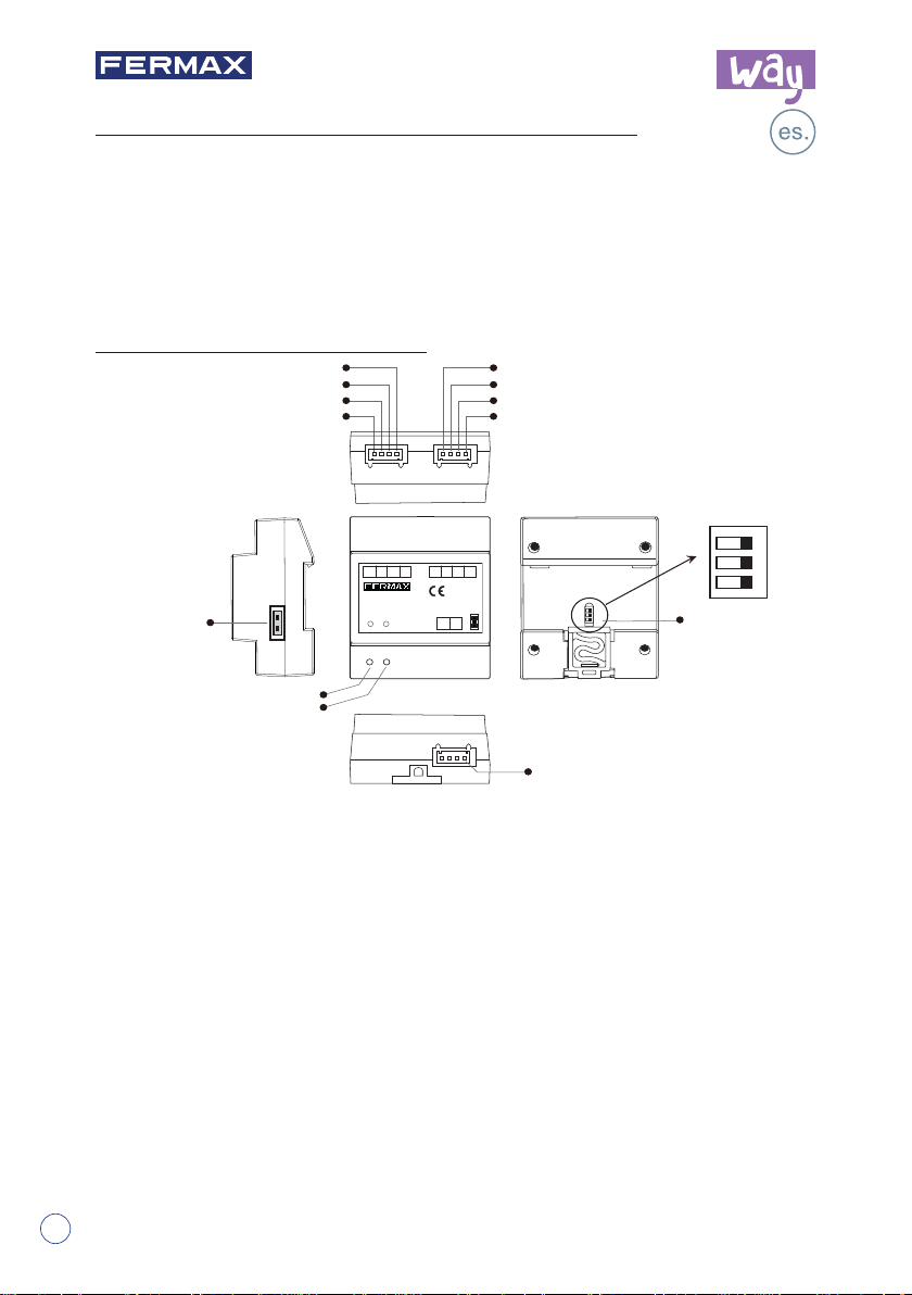
2.
Elementos y conexiones
RoHS
Compliant
12V
S2
S1
GND
ON
23
1
2
3
DIP
123
DIP
1
lock Control
Puente
Jumper
(jumper)
control
abrepuertas
1
2
3
POWER
POWER
IN-USE
IN-USE
COM
GND
NC
NO
12V S2 S1 GNDGND NO COM NC
2-WIRE SYSTEM
DT-RLC
GND NO COM NC
POWER IN-USE
POWER IN-USE
BUS BUS
12V S2 S1 GND
RISER
RISER
BUS BUS
REF 1418
MODULO RELE WAY
WAY RELAY MODULE
+12V:
12V salida alimentación. Puede usarse para alimentar el abrepuertas.
S2:
Reservado.
S1:
Contacto de botón de salida. Conexión del botón de salida entre los contactos S1
y GND.
GND:
Contacto de tierra común a los otros 3 contactos: S1, S2 y +12V.
NC:
Contacto normalmente cerrado para COM.
COM:
Contacto común del relé de abrepuertas.
NO:
contacto normalmente abierto para COM.
Puente control abrepuertas (jumper):
Vease apartados
POWER:
5, 6 y 7.
Indicador de funcionamiento, se encenderá cuando se conecte la
alimentación.
IN-USE:
Bus:
DIP:
Indicador de abrepuertas, se encenderá cuando se conecte el abrepuertas.
Conexión de la línea de bus, sin polaridad.
Utilizado para ajustar la dirección del relé.
2
BUS
Para seleccionar el tipo de abrepuertas:
Cod. 97840b V12_18
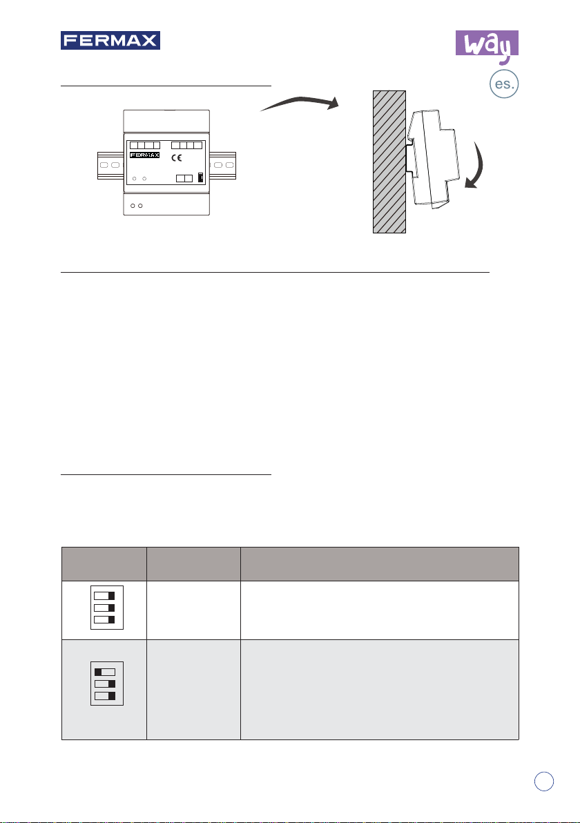
3.
Montaje
12V S2 S1 GNDGND NO COM NC
2-WIRE SYSTEM
DT-RLC
GND NO COM NC
REF 1418
MODULO RELE WAY
WAY RELAY MODULE
POWER IN-USE
POWER IN-USE
BUS BUS
12V S2 S1 GND
RISER
RISER
BUS BUS
RoHS
Compliant
1
2
3
Montaje carril DIN
4.
Cómo ajustar el tiempo de activación del abrepuertas
1). Dar alimentación y durante los 5 primeros segundos, cortocircuitar S2 y GND
durante 3 segundos, el indicador IN-USE parpadea.
2). Cortocircuitar S1 y GND durante 3 segundos. El indicador IN-USE se encenderá de
manera constante.
3). Volver a cortocircuitar S2 y GND. El tiempo que se mantenga este corticircuito es
equivalente al tiempo activación del abrepuertas. (El indicador IN-USE parpadea
una vez por segundo. El tiempo de ajuste máximo es de 30 segundos).
4). Una vez quitado el cortocircuito entre S2 y GND, el tiempo de abrepuertas queda
almacenado.
5.
Ajuste de interruptor DIP
El interruptor DIP en la parte trasera se utiliza para ajustar la dirección del relé. Por
favor, véase la información a continuación para obtener más detalles sobre los ajustes
DIP:
Ajustes del DIP para el abrepuertas
DIP Estado Bit Descripción
ON
23
OFF,OFF,OFF Para abrepuertas 1 de la puerta 1.
1
Relé para el control del segundo abrepuertas de la
ON
23
OFF,OFF,ON
1
puerta 1:
- Sin alimentador adicional (Esquema 6).
- Con alimentador adicional (Esquema 7):
• A) Con Abrepuertas eléctrico
• B) Con Abrepuertas magnético
-2-
NOTA: Ver esquemas (6-7) al fi nal de este manual.
3
1. About WAY RELAY Unit
Description:
The way relay is a unlock function device designed for DT system to control door locks.
It has the features as follows:
•Allows to open gate door locks;
•Support high power-consumption lock;
•With confi gurable unlock timed output;
•Support exit control button.
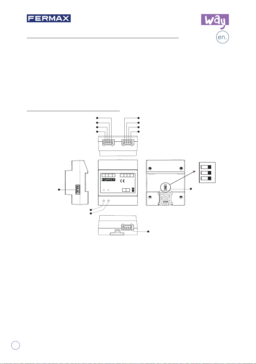
2.
Parts and Name
RoHS
Compliant
12V
S2
S1
GND
1
2
3
DIP
lock Control
Lock
Jumper
Control
NC
COM
NO
GND
12V S2 S1 GNDGND NO COM NC
2-WIRE SYSTEM
DT-RLC
GND NO COM NC
POWER IN-USE
BUS BUS
12V S2 S1 GND
RISER
RISER
BUS BUS
REF 1418
MODULO RELE WAY
1
2
3
WAY RELAY MODULE
POWER IN-USE
Jumper
POWER
POWER
IN-USE
IN-USE
BUS
+12V:
12V power output. Can be used to power the lock.
S2:
Reserved.
S1:
Exit button contact. Short this contact and the GND to unlock.
GND:
The common Ground of the other 3 contacts: S1, S2 and +12V.
NC:
The normally-closed contact to COM.
COM:
The common contact of the unlock relay.
NO:
The normally-open contact to COM.
Lock Control Jumper:
POWER:
IN-USE:
Bus:
DIP:
Working indicator, it will light up when plugs in power supply.
Unlock indicator,it will light up when unlock.
Connect to the bus line, no polarity.
Used for setting the address of the relay.
To select the lock type:
see section 5, 6 and 7.
ON
23
1
123
DIP
4
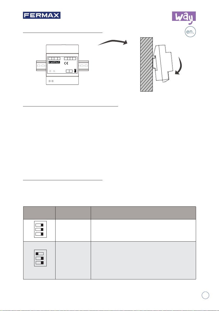
3.
Unit Mounting
12V S2 S1 GNDGND NO COM NC
2-WIRE SYSTEM
DT-RLC
GND NO COM NC
REF 1418
MODULO RELE WAY
WAY RELAY MODULE
POWER IN-USE
POWER IN-USE
BUS BUS
12V S2 S1 GND
RISER
RISER
BUS BUS
RoHS
Compliant
1
2
3
DIN Rail Mounting
4.
How to set the unlock delay time
1). Power-on within 5 seconds, short-circuit S2 up to 3 seconds, the IN-USE indicator
fl ash.
2). Short-circuit S1 up to 3 seconds, and the IN-USE indicator always light.
3). Short-circuit again S2, at this time,the short-circuit time equal to unlock delay time.
(the IN-USE indicator flashes once per second, Less than two seconds by one
second calculation; The maximum setting time is 30 seconds.)
4). After S2 released, saved unlock delay, and exit the setting.
5.
DIP Switch Setting
The DIP switch in the back of the panel is used to set the address of the relay. Please
refer to the followings for more detail informations about the DIP settings:
DIP settings for lock.
DIP Bit State Descriptions
ON
23
OFF,OFF,OFF Lock 1 of the panel 1.
1
Relay for control the second lock of the panel 1:
ON
23
OFF,OFF,ON
1
- Without external power supply (Wiring diagram 6).
- With external power supply (Wiring diagram 7):
• A) With Electric lock type
• B) With Magnetic lock type
-2-
NOTE: See diagrams (6-7) at the end of this manual.
5
 Loading...