

Fermax VIDEO CITYLINE DUOX 3L, VIDEO CITYLINE DUOX 5L, VIDEO CITYLINE DUOX 4L, VIDEO CITYLINE DUOX 6L, VIDEO CITYLINE DUOX 24L User& Installer's Manual
Page 1
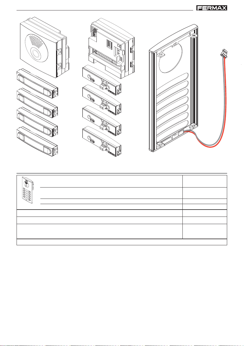
KIT VIDEO CITYLINE DUOX 3-24L
VIDEO CITYLINE DUOX KIT 3-24L
MANUAL DE INST ALADOR Y USUARIO
USER & INSTALLER’S MANUAL
ESPAÑOL
ENGLISH
Page 2

DUODUO
X CITYLINE KIT 3-24LX CITYLINE KIT 3-24L
DUO
X CITYLINE KIT 3-24L
DUODUO
X CITYLINE KIT 3-24LX CITYLINE KIT 3-24L
DUODUO
X CITYLINE KIT 3-24LX CITYLINE KIT 3-24L
DUO
X CITYLINE KIT 3-24L
DUODUO
X CITYLINE KIT 3-24LX CITYLINE KIT 3-24L
Publicación técnica de caracter informativo editada por FERMAX ELECTRONICA S.A.U.
FERMAX ELECTRONICA, en su política de mejora constante, se reserva el derecho a
modificar el contenido de este documento así como las características de los productos
que en él se refieren en cualquier momento y sin previo aviso.
Cualquier modificación será reflejada en posteriores ediciones de este documento.
¡ENHORABUENA POR ADQUIRIR UN PRODUCTO DE CALIDAD!
Fermax electrónica desarrolla y fabrica equipos de prestigio que cumplen los más altos
estándares de diseño y tecnología.
Su monitor de videoportero FERMAX le permitirá comunicarse con la placa de calle, ver la
persona que le está llamando y abrirle la puerta de entrada si así lo desea.
Esperamos disfrute de sus funcionalidades.
www.fermax.com
«KIT VIDEO CITYLINE DUOX 3-24L»
Cod. 97905EI V06_16
Pag 2
ESPAÑOL
Page 3

DUODUO
X CITYLINE KIT 3-24LX CITYLINE KIT 3-24L
DUO
X CITYLINE KIT 3-24L
DUODUO
X CITYLINE KIT 3-24LX CITYLINE KIT 3-24L
DUODUO
X CITYLINE KIT 3-24LX CITYLINE KIT 3-24L
DUO
X CITYLINE KIT 3-24L
DUODUO
X CITYLINE KIT 3-24LX CITYLINE KIT 3-24L
INDICE
SECCION I - MANUAL DEL INST ALADOR.................................................................. 5
Instalación del Alimentador ............................................................................ 6
Instalación de la placa de calle ..................................................................... 6
Instalación del monitor ................................................................................... 6
Ajustes de la placa .......................................................................................... 7
Restaurar a valores de fábrica: Reset............................................................. 10
- Reset Mapeado (código de llamada pulsador) ................................................. 10
- Programación Tiempos de apertura de puerta.........................................................10
- RESET parámetros a valores por defecto de fábrica (mediante un teclado) ........11
Precableado ..................................................................................................... 12
Características Técnicas ................................................................................ 15
Esquemas de cableado.................................................................................. 17
SECCION II - MANUAL DE USUARIO ......................................................................... 27
Monitor Veo ....................................................................................................... 28
- Botones .................................................................................................. 28
- Programación: Pantalla Menú Usuario ............................................... 29
1. Ajuste volumen melodías ............................................................. 29
2. Modo no molestar (cancelar tono de llamada) .......................... 29
3. Función F2...................................................................................... 30
4. Configuracion ................................................................................. 30
4.1) Melodias ................................................................................. 30
4.1.1) Selección melodía de placa ........................................... 30
4.1.2) Selección melodía conserjería ...................................... 31
4.2) Reset ........................................................................................ 31
4.3) Código QR ............................................................................... 31
- Ajustes: Video y Audio ........................................................................... 32
Video: Brillo - Contraste - Color .................................................... 32
Audio ................................................................................................ 33
- Funcionamiento ...................................................................................... 33
Pag 3
Page 4

DUODUO
X CITYLINE KIT 3-24LX CITYLINE KIT 3-24L
DUO
X CITYLINE KIT 3-24L
DUODUO
X CITYLINE KIT 3-24LX CITYLINE KIT 3-24L
DUODUO
X CITYLINE KIT 3-24LX CITYLINE KIT 3-24L
DUO
X CITYLINE KIT 3-24L
DUODUO
X CITYLINE KIT 3-24LX CITYLINE KIT 3-24L
Pag 4
Page 5

DUODUO
X CITYLINE KIT 3-24LX CITYLINE KIT 3-24L
DUO
X CITYLINE KIT 3-24L
DUODUO
X CITYLINE KIT 3-24LX CITYLINE KIT 3-24L
DUODUO
X CITYLINE KIT 3-24LX CITYLINE KIT 3-24L
DUO
X CITYLINE KIT 3-24L
DUODUO
X CITYLINE KIT 3-24LX CITYLINE KIT 3-24L
Sección I - Manual del Instalador
Pag 5
Page 6
DUODUO
X CITYLINE KIT 3-24LX CITYLINE KIT 3-24L
DUO
X CITYLINE KIT 3-24L
DUODUO
X CITYLINE KIT 3-24LX CITYLINE KIT 3-24L
DUODUO
X CITYLINE KIT 3-24LX CITYLINE KIT 3-24L
DUO
X CITYLINE KIT 3-24L
DUODUO
X CITYLINE KIT 3-24LX CITYLINE KIT 3-24L
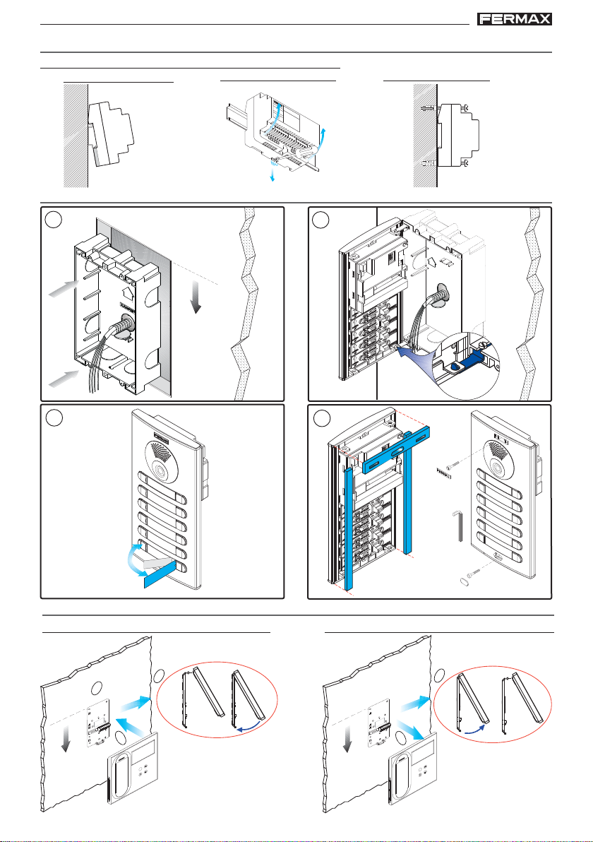
INSTALACIÓN DEL ALIMENT ADOR
Instalación en carril DIN - DIN rail Installation
Montaje
Desmontaje
INSTALACIÓN PLACA DE CALLE
Fijación con tornillos
M
A
DE
I
N
S
PA
IN
5
0
6
0
H
z
.
5
0
V
A
M
A
F
X
+
.
U
1
8
E
V
N
T
1
E
2
1
A
V
.
5
LIM
A
KIT DIGITAL
1
E
A
N
T
A
C
IO
N
1
5.57 feet
3
IA
AR
M
A
C
R
O
L
INSTALACIÓN DEL MONITOR
Montaje
2
1.70m
4
Desmontaje
5.25 feet
Pag 6
1.60m
2
1
1
B
o
u
t
B
o
u
t
B
i
n
B
i
n
3
1
F
1.60m
5.25 feet
B
o
u
t
B
o
u
t
B
i
n
B
i
n
2
1
F
Page 7
DUODUO
X CITYLINE KIT 3-24LX CITYLINE KIT 3-24L
DUO
X CITYLINE KIT 3-24L
DUODUO
X CITYLINE KIT 3-24LX CITYLINE KIT 3-24L
DUODUO
X CITYLINE KIT 3-24LX CITYLINE KIT 3-24L
DUO
X CITYLINE KIT 3-24L
DUODUO
X CITYLINE KIT 3-24LX CITYLINE KIT 3-24L
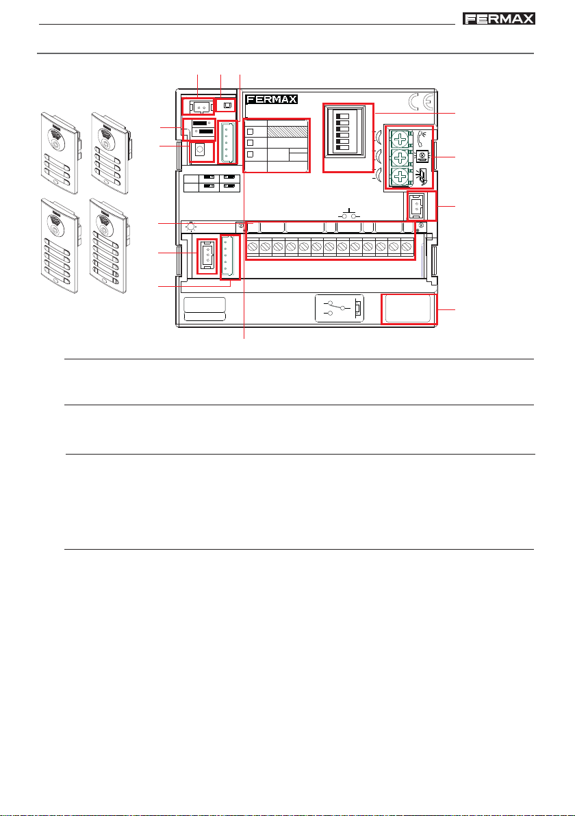
AJUSTES DE LA PLACA
C)
A)B)
IDIOMA
LANGUAGE
EXIT
+12
BS
AMPLIFICADOR
AMPLIFIER
ON
A
B
C
D
E
F
-
S
18Vdc
+
AUDIO
GND
H)
I )
J)
MIC
P1
M)
D)
E)
CN9
JP1
JP2
SW1
SW1 PROG
JP1
LEDS ON
JP2
TERM ON
CN1
DL2
LEDS OFF
TERM OFF
ONE
TO
ONE
CN3CN2
CN9 TAMPER
PACK
CN1
TYPE
EG
BK
SB
PL
Nº
BUS
B
P2
DUOX VIDEO
EXTENSION
Nº
BK
C
B
NCNO
F)
A)
G)
ALIMENTACION
POWER SUPPLY
18 Vdc
-+
L)
NC
C
NO
VERSION
:
K)
CN1
Conexión módulo de extensión de llamadas, teclado.
B)
CN9
Conexión Tamper (mediante conector stocko macho paso 2mm).
C)
DL2
Led de Modo:
• Intermitente lento (1 parpadeo / 1 seg): Programación Inversa o Secuencial. Ver
Manual Avanzado de Programación DUOX VIDEO cod. 97902.
• Apagado: reposo.
D)
Placa MÁSTER:
La programación de los terminales de vivienda se realiza siempre desde la placa
•
activada como MÁSTER.
• En cualquier instalación sólo puede haber una placa MÁSTER a la vez, ya sea una
instalación de un sólo bloque o de varios, ya esté configurada como placa de subbloque, de bloque o entrada general.
• Una placa de calle se configura como MÁSTER mediante el pulsador SW1 del
amplificador. Si se pulsa el botón SW1 3 veces consecutivas rápidas se activará la
placa como MÁSTER y se oirá un tono de confirmación (bip-bip), transcurridos 2
segundos.
• Cuando se selecciona una placa como MÁSTER, ésta avisa al resto de la situación
y si hubiera anteriormente una así configurada, dejará de serlo automáticamente.
• En caso de haber varios bloques en una instalación será recomendable utilizar la
placa de la entrada general como MÁSTER ya que permite programar todos los
teléfonos/monitores de ésta.
Pag 7
Page 8
DUODUO
X CITYLINE KIT 3-24LX CITYLINE KIT 3-24L
DUO
X CITYLINE KIT 3-24L
DUODUO
X CITYLINE KIT 3-24LX CITYLINE KIT 3-24L
DUODUO
X CITYLINE KIT 3-24LX CITYLINE KIT 3-24L
DUO
X CITYLINE KIT 3-24L
DUODUO
X CITYLINE KIT 3-24LX CITYLINE KIT 3-24L
• Es recomendable una vez terminada la configuración de los terminales desactivar
la placa MÁSTER para evitar reprogramaciones de terminales accidentales.
• La placa se desactiva del modo máster siguiendo el mismo procedimiento de
activación: 3 pulsaciones seguidas rápidas del botón SW1. Se oirá un tono de
desactivación (bop), transcurridos 2 segundos.
Configuración - Programación del Amplificador
El amplificador DUOX se puede configurar para permitir un funcionamiento como
placa de entrada general, entrada de bloque o entrada de sub-bloque.
• El sistema DUOX emplea direcciones de terminal de vivienda de 6 dígitos.
• Los dígitos del código de llamada se organizan de la siguiente manera: BBSSNN:
- BB: indica el número de Bloque, (de 00 a 99).
- SS: indica el número de sub-bloque, (de 00 a 99).
- NN: indica el número de vivienda del sub-bloque, (de 00 a 99).
No es necesario segregar la instalación según ésta jerarquía ya que el sistema se
adapta a las necesidades de la instalación.
NOT A IMPORT ANTE:
Configuración de parámetros por el instalador.
Para realizar la configuración en la placa de pulsadores Cityline ver ANEXO:
Configuración asistida por voz en placas de pulsadores. Instrucción incluida en
este equipo.
También se puede realizar la configuración conectando temporalmente un teclado
ref. 7439, descargar el manual de Programación Placas Direct Video Duox cod.
97900 en www.fermax.com.
E)
Conectores Placa:
• Bornas de Conexión del sistema:
B,B: Bus DUOX: alimentación teléfonos/monitores, datos, audio y video.
C, NO, NC: contactos relé,
2A@30Vdc (conexión abrepuertas).
+12: salida12 Vdc-250mA (máximo 500mA durante 100 segundos).
BS, -: pulsador zaguán.
S, -: entrada sensor de puerta.
+, GND: No disponible. Futuras versiones.
P1-P2: conexión pulsador/es.
F)
CN2
Conexión pulsadores individuales placa perfil continuo Cityline
G)
CN3
Conexión Módulo OneToOne
H)
Pag 8
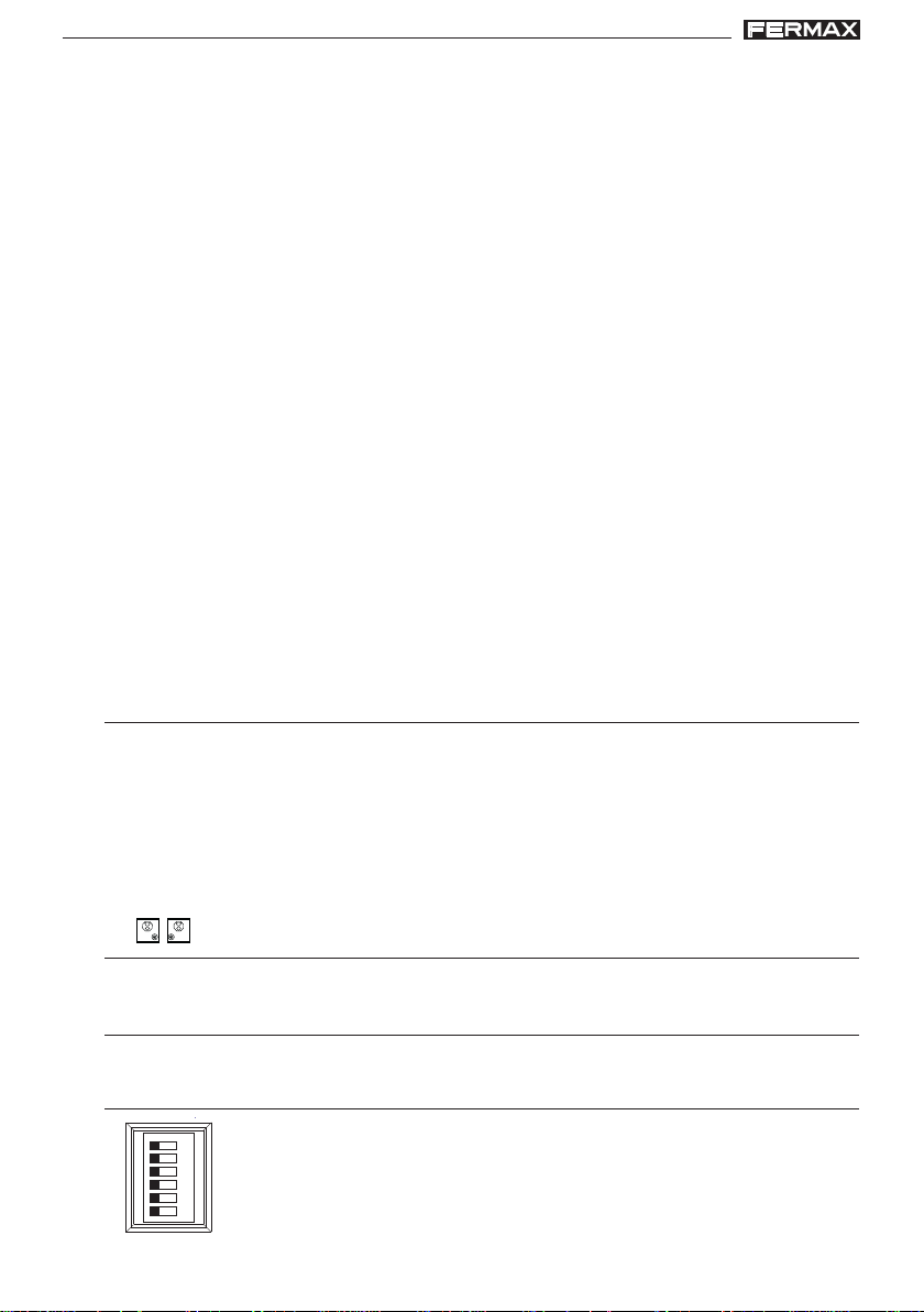
A
B
C
D
E
F
ON
Selección del idioma del mensaje de «puerta abierta» y mensajes
de configuración asistida por voz.
Ver CODIFICACIÓN al final de la SECCIÓN I: Manual del Instalador.
Page 9
DUODUO
X CITYLINE KIT 3-24LX CITYLINE KIT 3-24L
DUO
X CITYLINE KIT 3-24L
DUODUO
X CITYLINE KIT 3-24LX CITYLINE KIT 3-24L
DUODUO
X CITYLINE KIT 3-24LX CITYLINE KIT 3-24L
DUO
X CITYLINE KIT 3-24L
DUODUO
X CITYLINE KIT 3-24LX CITYLINE KIT 3-24L
I)
Ajuste audio
“puerta abierta”
J)
MIC
Conexión micrófono (micrófono ubicado en el perfil inferior de la placa)
K)
Versión del amplificador
L)
Etiqueta datos de programación. Rellenar los campos de la etiqueta correspondientes a la
programación realizada.
Ejemplo 1: Programación como Entrada General y Placa número 3.
TYPE
X
EG
Nº
BK
SB
PL
Nº
Ejemplo 2: Programación como Bloque 1 y Placa número 2.
TYPE
BK
3
Nº
EG
BK
SB
PL
TYPE
01
BK
2
Nº
X
Nº
Ejemplo 3: Programación como Sub- Bloque 2 y Placa número 3, perteneciente al Bloque 1.
EG
BK
02
3
BK
01
X
Nº
SB
PL
Pag 9
Page 10

DUODUO
X CITYLINE KIT 3-24LX CITYLINE KIT 3-24L
DUO
X CITYLINE KIT 3-24L
DUODUO
X CITYLINE KIT 3-24LX CITYLINE KIT 3-24L
DUODUO
X CITYLINE KIT 3-24LX CITYLINE KIT 3-24L
DUO
X CITYLINE KIT 3-24L
DUODUO
X CITYLINE KIT 3-24LX CITYLINE KIT 3-24L
M)
JP1
Leds cámara
JP2
Terminación de línea integrada en el amplificador para su posible uso.
NOT A IMPORT ANTE:
Enfoque de la cámara
Para ajustar la imagen de la cámara, ver ANEXO: Configuración asistida por voz en
placas de pulsadores. Instrucción incluida en este equipo.
También se puede realizar el ajuste conectando temporalmente un teclado (ref. 7439) o
por medio del programador duox (ref. 3254) conectado localmente.
Se pueden descargar los manuales en: www.fermax.com
- Manual de Programación Placas Direct Video Duox, cod. 97900.
- Manual Programador DUOX ref 3254, cod. 97731.
Llamada Amplificador DUOX:
• Las placas con la dirección «0» de cada bloque permitirán realizar la comunicación
con los teléfonos cuando se descuelguen o con los monitores si realiza el
autoencendido con ésta y el canal de comunicación está libre. Si no se desea esa
funcionalidad no hay que dejar placas con esa dirección. Los monitores también
tienen la posibilidad de realizar el autoencendido con la placa 1 de su bloque y la
placa 0 de la Entrada General.
• Se realizará la llamada a la vivienda, pulsando el botón correspondiente.
LEDS ON
encendidos cuando la camara está
activada
LEDS OFF
apagados siempre
RESTAURAR A V ALORES DE FÁBRICA: Reset
El amplificador DUOX dispone de la función de «Reset» que permite restaurar los
parámetros programados a valores de fábrica.
RESET Mapeado (codigo de llamada pulsador)
1º- Resetear el amplificador: quitar alimentación.
2º- Con el botón SW1 pulsado, dar alimentación y mantener pulsado el botón SW1
durante 5 segundos. El led parpadeará rápidamente para indicar que se ha realizado
la restauración del mapeado de pulsadores.
Programación Tiempos de apertura de puerta
Los tiempos de activación de abrepuerta programables son dos:
- Tiempo de apertura de puerta desde vivienda
- Tiempo de apertura de puerta desde botón de salida (conectado a bornas «BS» y «-»).
Notas:
• Valores :
- Tiempo abrepuertas: 01..99 seg. (por defecto: 03).
- Tiempo botón salida: 00..99 seg. (por defecto: 06). Desactivado: 00.
Pag 10
Page 11

DUODUO
X CITYLINE KIT 3-24LX CITYLINE KIT 3-24L
DUO
X CITYLINE KIT 3-24L
DUODUO
X CITYLINE KIT 3-24LX CITYLINE KIT 3-24L
DUODUO
X CITYLINE KIT 3-24LX CITYLINE KIT 3-24L
DUO
X CITYLINE KIT 3-24L
DUODUO
X CITYLINE KIT 3-24LX CITYLINE KIT 3-24L
Los tiempos de apertura de puerta se pueden cambiar mediante diferentes formas:
a) Programación asistida por voz.
Es posible programar los tiempos de apertura mediante la configuración asistida por
voz del amplificador.
Para más información ver ANEXO: Configuración asistida por voz en placas de pul-
sadores. Instrucción incluida en este equipo.
b) Programación desde teclado.
También es posible programar los tiempos de apertura mediante un teclado ref. 7439.
Para introducir los valores numéricos, es necesario conectar temporalmente este
teclado.
Para más información descargar el manual de Programación Placas Direct Video
Duox, cod. 97900, disponible en www.fermax.com. La conexión del teclado y el amplificador se detalla en dicho manual.
c) Mediante manipulación eléctrica.
Realizar los siguientes pasos:
1º. Con la alimentación desconectada, realice un cortocircuito entre las bornas «Bs»
y «-» (negativo) del amplificador.
2º. Manteniendo el cortocircuito anterior conecte la alimentación del sistema. El
amplificador generará tantos ‘‘bips’’ como segundos haya programado para el
tiempo de apertura desde vivienda.
2.1.Si se desea cambiar ese valor se debe pulsar cualquier botón de llamada
tantas veces como segundos se quiera programar.
2.2.Si no se quiere cambiar basta con dejar pasar 10" sin pulsar ningún botón de
llamada.
Después el amplificador generará tantos ‘‘bips’’ como segundos haya programado
3º.
para el el tiempo de apertura desde el pulsador de salida.
3.1.Si se desea cambiar ese valor se debe pulsar cualquier botón de llamada
tantas veces como segundos se quiera programar.
3.2.Si no se quiere cambiar basta con dejar pasar 10" sin pulsar ningún botón de
llamada.
4º. Salir de programación:
Para salir de programación, permanecer 10 segundos sin pulsar ninguna tecla.
Sonará un ‘‘bip bip’’ indicando la salida de programación de tiempos.
A partir de este momento se puede quitar el cortocircuito entre las bornas «Bs» y
5º.
«-» (negativo) del amplificador y se puede utilizar el amplificador con normalidad.
RESET de parámetros a valores por defecto de fábrica (mediante un teclado)
Se puede realizar un Reset de parámetros a valores por defecto de fábrica. Para ello es
necesario conectar temporalmente un teclado (ref. 7439) para introducir los valores
numéricos. Descargar el manual de Programación Placas Direct Video Duox, cod. 97900,
en www.fermax.com.
Pag 11
Page 12
DUODUO
X CITYLINE KIT 3-24LX CITYLINE KIT 3-24L
DUO
X CITYLINE KIT 3-24L
DUODUO
X CITYLINE KIT 3-24LX CITYLINE KIT 3-24L
DUODUO
X CITYLINE KIT 3-24LX CITYLINE KIT 3-24L
DUO
X CITYLINE KIT 3-24L
DUODUO
X CITYLINE KIT 3-24LX CITYLINE KIT 3-24L
PRECABLEADO
Conexión módulo de extensión de llamadas (ref. 2008)
CN9
JP1
JP2
JP3
JP2
PREVIOUS
CN1
REF. 2008
CN1
PREVIOUS
18345
2
CN3
7
8
5
6
3
4
1
2
7
6
CN4
CN2
NEXT
SW1
SW1 PROG
JP1
LEDS ON
JP2
TERM ON
ALIMENTACION
POWER SUPPLY
18 Vdc
-+
ARRIBA
UP
ARRIBA
UP
ARRIBA
UP
PACK
CN1
EXTENSION
TYPE
Nº
EG
BK
BK
SB
CN1
PL
Nº
LEDS OFF
TERM OFF
ONE
TO
8
ONE
BUS
CN3CN2
C
B
B
P2
-
+
CP
DUOX VIDEO
CN9 TAMPER
DL2
AMPLIFICADOR
AMPLIFIER
ON
A
AUDIO
B
C
D
E
F
IDIOMA
LANGUAGE
EXIT
18Vdc
+12
NCNO
NC
NO
+
BS
-
S
C
GND
VERSION
MIC
7
P1
:
56
4
2
3
1
Conexión varios módulos de extensión de llamadas ref. 2008 (más de 8 pulsadores)
Pag 12
9
7
15
3
1
16
.......
10
8
4
2
Al amplificador
CN1
PREVIOUS
REF. 2008
18345
2
CN3
Pulsadores
(1...8)
1
6
NEXT - CN2
7
CN4
PREVIOUS - CN1PREVIOUS - CN1
PREVIOUS
REF. 2008
18345
2
CN3
Pulsadores
(9...16)
2
7
6
CN4
CN2
NEXT
Page 13
DUODUO
X CITYLINE KIT 3-24LX CITYLINE KIT 3-24L
DUO
X CITYLINE KIT 3-24L
DUODUO
X CITYLINE KIT 3-24LX CITYLINE KIT 3-24L
DUODUO
X CITYLINE KIT 3-24LX CITYLINE KIT 3-24L
DUO
X CITYLINE KIT 3-24L
DUODUO
X CITYLINE KIT 3-24LX CITYLINE KIT 3-24L
Conexión módulo de extensión de llamadas (ref.2441)
REF.2441
MODULO EXTENSION 16 LLAMADAS
16 CALL EXTENSION PACK
1312 1614 15
2134 8567119
10
CN9
JP1
JP2
JP3
JP2
SW1
SW1 PROG
JP1
LEDS ON
JP2
TERM ON
ALIMENTACION
POWER SUPPLY
18 Vdc
-+
ARRIBA
UP
ARRIBA
UP
ARRIBA
UP
NCNO
12
10
AMPLIFICADOR
AMPLIFIER
ON
A
AUDIO
B
C
D
E
F
IDIOMA
LANGUAGE
EXIT
18Vdc
+12
+
BS
-
S
NC
C
NO
GND
VERSION
13
MIC
P1
:
11
9
8
7
EG
BK
SB
PL
BUS
B
-
+
PACK
EXTENSION
B
DUOX VIDEO
Nº
BK
C
CN9 TAMPER
DL2
CN1
TYPE
CN1
Nº
LEDS OFF
TERM OFF
ONE
TO
14
ONE
CN3CN2
P2
+
-
CP
ARRIBA
UP
ARRIBA
UP
14
13
12
11
9
10
7
8
5
6
3
4
1
2
ARRIBA
UP
6
4
2
5
3
1
Pag 13
Page 14
DUODUO
X CITYLINE KIT 3-24LX CITYLINE KIT 3-24L
DUO
X CITYLINE KIT 3-24L
DUODUO
X CITYLINE KIT 3-24LX CITYLINE KIT 3-24L
DUODUO
X CITYLINE KIT 3-24LX CITYLINE KIT 3-24L
DUO
X CITYLINE KIT 3-24L
DUODUO
X CITYLINE KIT 3-24LX CITYLINE KIT 3-24L
Conexión varios módulos de extensión de llamadas ref. 2441 (más de 16 pulsadores)
1
REF.2441
SIGUIENTE/NEXT
ANTERIOR/PREVIOUS
Al amplificador
31
32
......
19
20
17
18
15
16
3
4
1
2
PACK EXTENSION 16 LLAMADAS
16 EXTENSION CALL PACK
LLAMADAS/CALLS
1
43276510981211 151413 16
Pulsadores
(1...16)
2
REF.2441
SIGUIENTE/NEXT
ANTERIOR/PREVIOUS
PACK EXTENSION 16 LLAMADAS
16 EXTENSION CALL PACK
LLAMADAS/CALLS
1
43276510981211 151413 16
Pulsadores
(17...32)
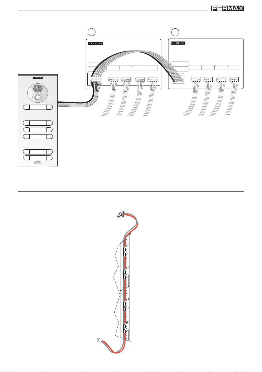
REPOSICIÓN O CAMBIO DE MÓDULOS
Si por cualquier motivo tiene que cambiar algún módulo de la placa, recuerde que no debe colocar el
cable del micrófono insertado a lo largo del perfil de la placa. Aconsejamos ubicarlo en los clipajes de los
módulos. Ver detalle.
Pag 14
MIC
Page 15
DUODUO
X CITYLINE KIT 3-24LX CITYLINE KIT 3-24L
DUO
X CITYLINE KIT 3-24L
DUODUO
X CITYLINE KIT 3-24LX CITYLINE KIT 3-24L
DUODUO
X CITYLINE KIT 3-24LX CITYLINE KIT 3-24L
DUO
X CITYLINE KIT 3-24L
DUODUO
X CITYLINE KIT 3-24LX CITYLINE KIT 3-24L
CARACTERÍSTICAS TÉCNICAS
MIC
Alimentación
Consumo
en reposo
IP43 / IK07
Potencia audio sentido vivienda-calle
Potencia audio sentido calle-vivienda
Temperatura de funcionamiento
Volumen regulable en ambos sentidos
audio activo
iluminación
Valores:
- Tiempo activación abrepuertas: 01..99 seg. (por defecto: 03).
- Tiempo activación botón salida: 00..99 seg. (por defecto: 06). Desactivado: 00.
- Tiempo de conversación máximo: 90 seg.
- Tipo de Placa: sub-bloque/bloque/general, (por defecto: bloque).
- Número Bloque: 00..99, (por defecto: 00).
- Número Sub-Bloque: 00..99, (por defecto: 00).
- Número Placa: 0..9, (por defecto: 0).
- Tiempo sensor de puerta: 000..250, (por defecto: 000, no activo).
- Código apertura: 0000..9999, (por defecto: no activo).
- Código programación: 0000..9999, (por defecto: 4444).
- Placa MÁSTER: no activa.
18 Vdc
165 mA
275/480 (max) mA
35 mA
1 W
0,15 W
[-25º , +55ºC]
[-13º, 131ºF]
Pag 15
Page 16
DUODUO
X CITYLINE KIT 3-24LX CITYLINE KIT 3-24L
DUO
X CITYLINE KIT 3-24L
DUODUO
X CITYLINE KIT 3-24LX CITYLINE KIT 3-24L
DUODUO
X CITYLINE KIT 3-24LX CITYLINE KIT 3-24L
DUO
X CITYLINE KIT 3-24L
DUODUO
X CITYLINE KIT 3-24LX CITYLINE KIT 3-24L
- Volumen monitorización: 0..9, (por defecto: 5).
- Tiempo en programación secuencial de pulsadores tras cese actividad: 60 seg.
- Tiempo en programación inversa de pulsadores tras cese actividad: 300 seg.
Capacidades:
• Llamadas desde Placa Pulsadores: 99.
• Llamadas desde Placa Teclado:
- Sub-Bloque: 99.
- Bloque: 9999.
- Entrada General: 999999.
• Número de Placas:
- Entradas Generales: 10.
- Bloque: 10.
- Sub-Bloque: 10.
F1
Temperatura de funcionamiento
Humedad
Pantalla OSD
Resolución
Dimensiones
TFT 4.3”
Alimentación
Consumo
Reposo
Audio + video
18 Vdc
25 mA
230 mA
[-5, +40 °C]
[0% - 90%]
Hor.: 480 Line TV
Ver.: 272 Line TV
200 x 200 x 46 mm
8” x 8” x 1,8”
Pag 16
Page 17

DUODUO
X CITYLINE KIT 3-24LX CITYLINE KIT 3-24L
DUO
X CITYLINE KIT 3-24L
DUODUO
X CITYLINE KIT 3-24LX CITYLINE KIT 3-24L
DUODUO
X CITYLINE KIT 3-24LX CITYLINE KIT 3-24L
DUO
X CITYLINE KIT 3-24L
DUODUO
X CITYLINE KIT 3-24LX CITYLINE KIT 3-24L
Esquemas de cableado
Pag 17
Page 18
DUODUO
JP1
JP1
X CITYLINE KIT 3-24LX CITYLINE KIT 3-24L
DUO
X CITYLINE KIT 3-24L
DUODUO
X CITYLINE KIT 3-24LX CITYLINE KIT 3-24L
DUODUO
X CITYLINE KIT 3-24LX CITYLINE KIT 3-24L
DUO
X CITYLINE KIT 3-24L
DUODUO
X CITYLINE KIT 3-24LX CITYLINE KIT 3-24L
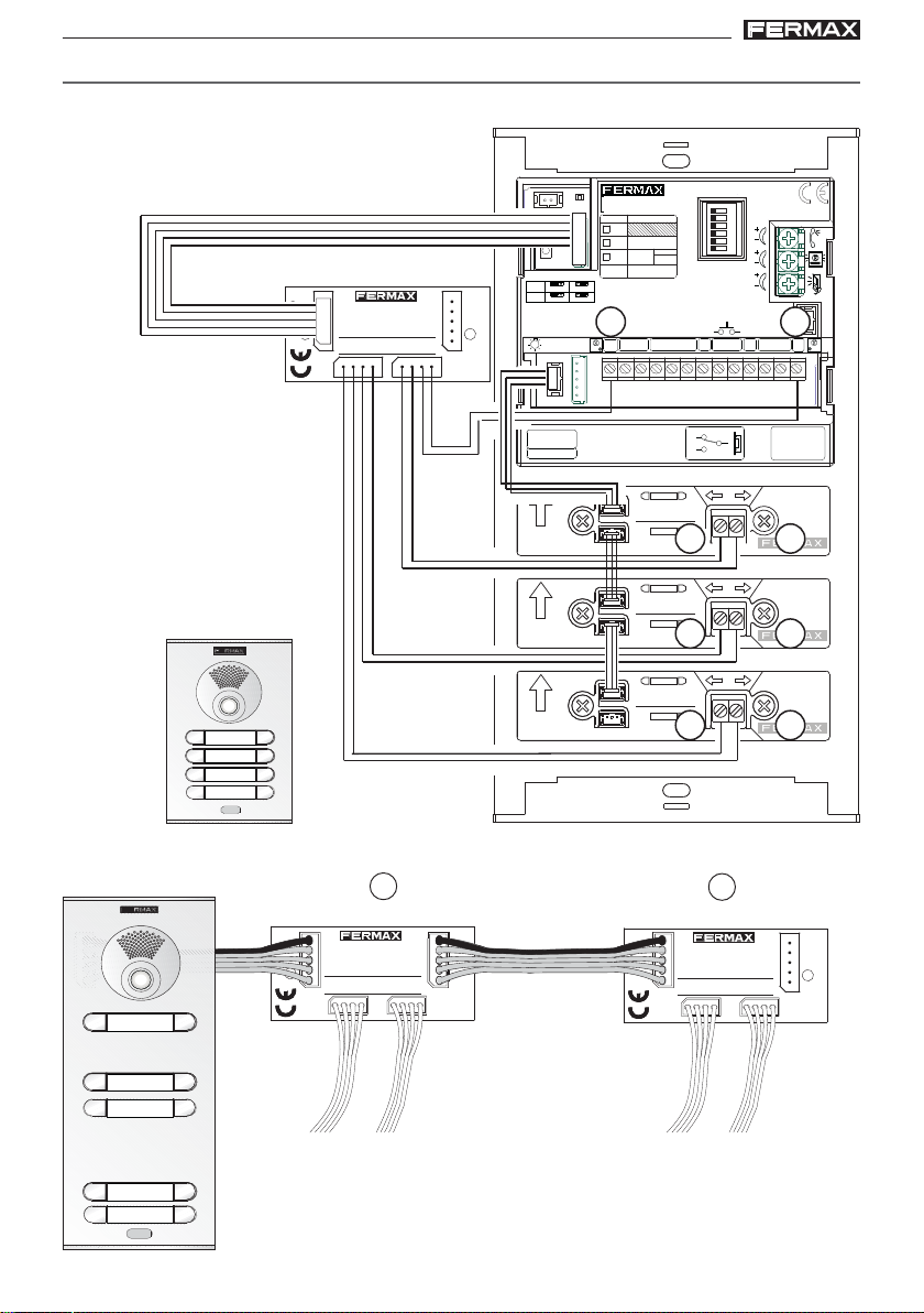
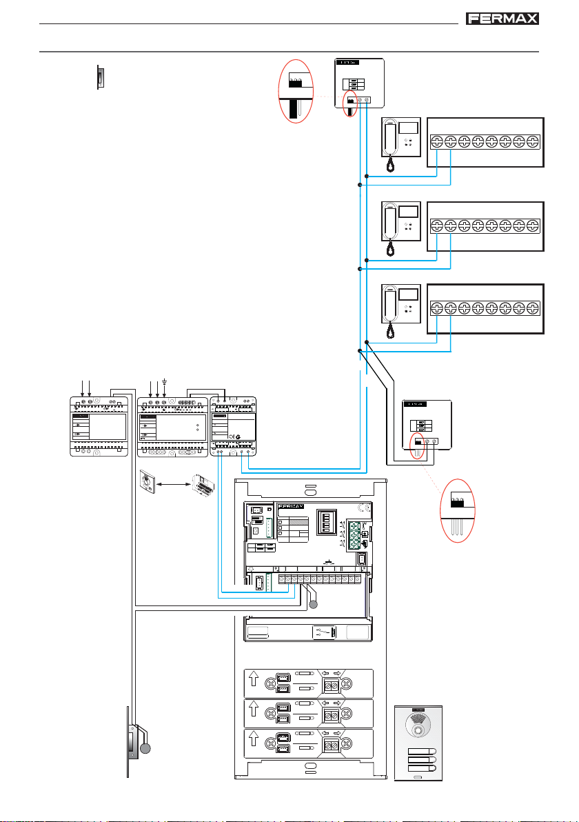
CABLEADO
Kit 3L & 12 Vac
A
DUOX LINE
ADAPTOR
REF: 3255
JP1
JP1
A
B
C
B
B
in
BinB
F1
outBout
+A F1
-
TB
in
BinB
B
C
outBout
in
BinB
outBout
A
B
C
B
F1
F1
Vac
230 V
~
INPUT
12Vac
230V ; 0,2 A
~
50-60 Hz
OUTPUT
12 V ; 1,5 A
~
12 Vac
~
~
Vac
~
100-240V
~
INPUT
18Vdc
100-240V ; 0,5 A
~
50-60 Hz
OUTPUT
18 V ; 1,5 A
D. max.
Ver tabla
seccionesdistancias
18 Vdc
ON
OVERLOAD
M
A
D
E
I
N
S
P
A
I
N
5
0
6
0
H
z
.
5
0
V
A
M
A
F
+
X
.
U
1
8
E
V
N
T
1
E
2
1
V
A
.
5
L
A
I
K
M
1
I
E
T
A
N
T
D
A
I
C
G
I
O
I
T
A
L
18 Vdc IN
MADE IN SPAIN
REF. 3244
INPUT
18Vdc/2A
OUTPUT
18Vdc/2A
PWR BUS PWR BUS
N
PREV BUS
DUOX POWER
SUPPLY ADAPTER MODULE
Ref. 3244
CN9
JP1
SW1 PROG
JP1
JP2
DUOX VIDEO
CN9 TAMPER
DL2
PACK
CN1
EXTENSION
TYPE
Nº
EG
JP2
BK
BK
SB
SW1
CN1
PL
Nº
LEDS ON
LEDS OFF
TERM OFF
TERM ON
ONE
TO
ONE
BUS
CN3CN2
C
B
B
P2
B in
B in
DUOX LINE
ADAPTOR
REF: 3255
JP1
JP1
AMPLIFICADOR
AMPLIFIER
ON
A
AUDIO
B
C
D
E
F
IDIOMA
LANGUAGE
EXIT
+12
NCNO
BS
MIC
18Vdc
+
GND
P1
-
S
+A F1
-
+A F1
-
TB
TB
NC
VERSION
ALIMENTACION
POWER SUPPLY
18 Vdc
-+
ARRIBA
UP
ARRIBA
UP
ARRIBA
12 Vac
UP
NO
+
CP
+
CP
+
CP
:
C
Pag 18
Page 19
DUODUO
JP1
JP1
X CITYLINE KIT 3-24LX CITYLINE KIT 3-24L
DUO
X CITYLINE KIT 3-24L
DUODUO
X CITYLINE KIT 3-24LX CITYLINE KIT 3-24L
DUODUO
X CITYLINE KIT 3-24LX CITYLINE KIT 3-24L
DUO
X CITYLINE KIT 3-24L
DUODUO
X CITYLINE KIT 3-24LX CITYLINE KIT 3-24L
Kit 4-5L & 12 Vac
Vac
230 V
~
INPUT
12Vac
230V ; 0,2 A
~
50-60 Hz
OUTPUT
12 V ; 1,5 A
~
12 Vac
~
~
Vac
~
100-240V
~
INPUT
100-240V ; 0,5 A
~
50-60 Hz
OUTPUT
18 V ; 1,5 A
18Vdc
D. max.
18 Vdc
ON
OVERLOAD
M
A
D
E
I
N
S
P
A
I
N
5
0
6
0
H
z
.
5
0
V
A
M
A
X
F
+
.
U
1
8
E
V
N
T
1
E
2
1
V
A
.
5
L
A
I
K
M
1
I
E
T
A
N
T
D
A
I
C
G
I
O
I
T
N
A
L
18 Vdc IN
SUPPLY ADAPTER MODULE
MADE IN SPAIN
REF. 3244
INPUT
18Vdc/2A
Ref. 3244
OUTPUT
18Vdc/2A
PWR BUS PWR BUS
A
DUOX POWER
DUOX LINE
ADAPTOR
REF: 3255
A
JP1
B
C
JP1
B
B
in
BinB
in
BinB
outBout
outBout
F1
F1
+A F1
-
+A F1
-
TB
TB
B in
B in
PREV BUS
DUOX LINE
ADAPTOR
REF: 3255
JP1
JP1
A
B
C
B
B
Ver tabla
secciones-
distancias
12 Vac
CN9
JP1
JP2
SW1
SW1 PROG
JP1
JP2
ALIMENTACION
POWER SUPPLY
-+
ARRIBA
UP
ARRIBA
UP
ARRIBA
UP
ARRIBA
UP
ARRIBA
UP
CN9 TAMPER
DL2
PACK
CN1
TYPE
EG
BK
SB
CN1
PL
Nº
LEDS ON
LEDS OFF
TERM OFF
TERM ON
ONE
TO
ONE
BUS
CN3CN2
B
P2
18 Vdc
+
CP
+
CP
+
CP
+
CP
+
CP
B
EXTENSION
Nº
C
DUOX VIDEO
BK
IDIOMA
LANGUAGE
+12
NCNO
BS
NC
NO
ON
EXIT
C
AMPLIFICADOR
AMPLIFIER
A
B
C
D
E
F
-
S
AUDIO
C
MIC
18Vdc
+
GND
P1
VERSION
:
Pag 19
Page 20
DUODUO
JP1
JP1
X CITYLINE KIT 3-24LX CITYLINE KIT 3-24L
DUO
X CITYLINE KIT 3-24L
DUODUO
X CITYLINE KIT 3-24LX CITYLINE KIT 3-24L
DUODUO
X CITYLINE KIT 3-24LX CITYLINE KIT 3-24L
DUO
X CITYLINE KIT 3-24L
DUODUO
X CITYLINE KIT 3-24LX CITYLINE KIT 3-24L
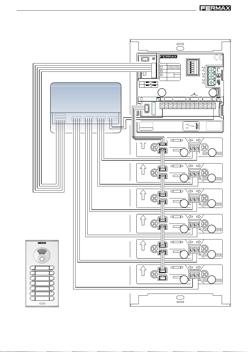
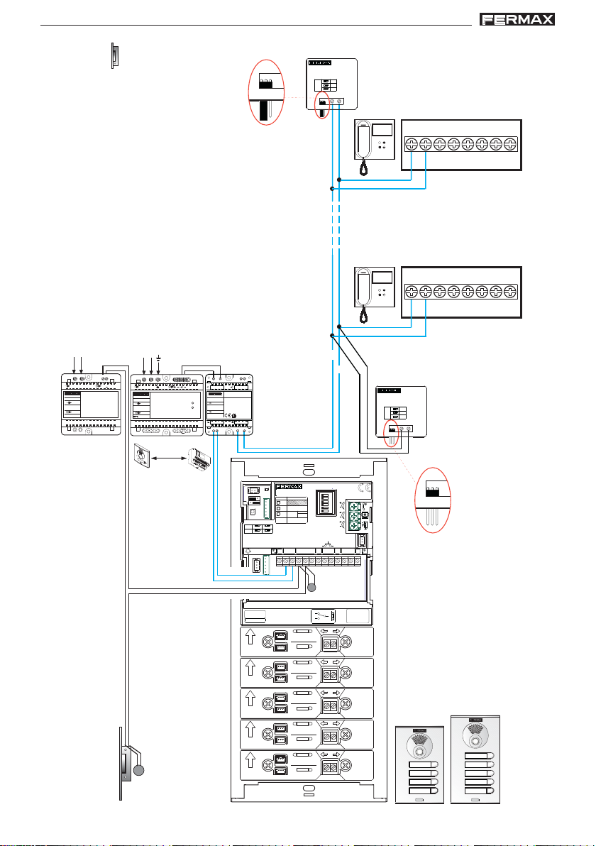
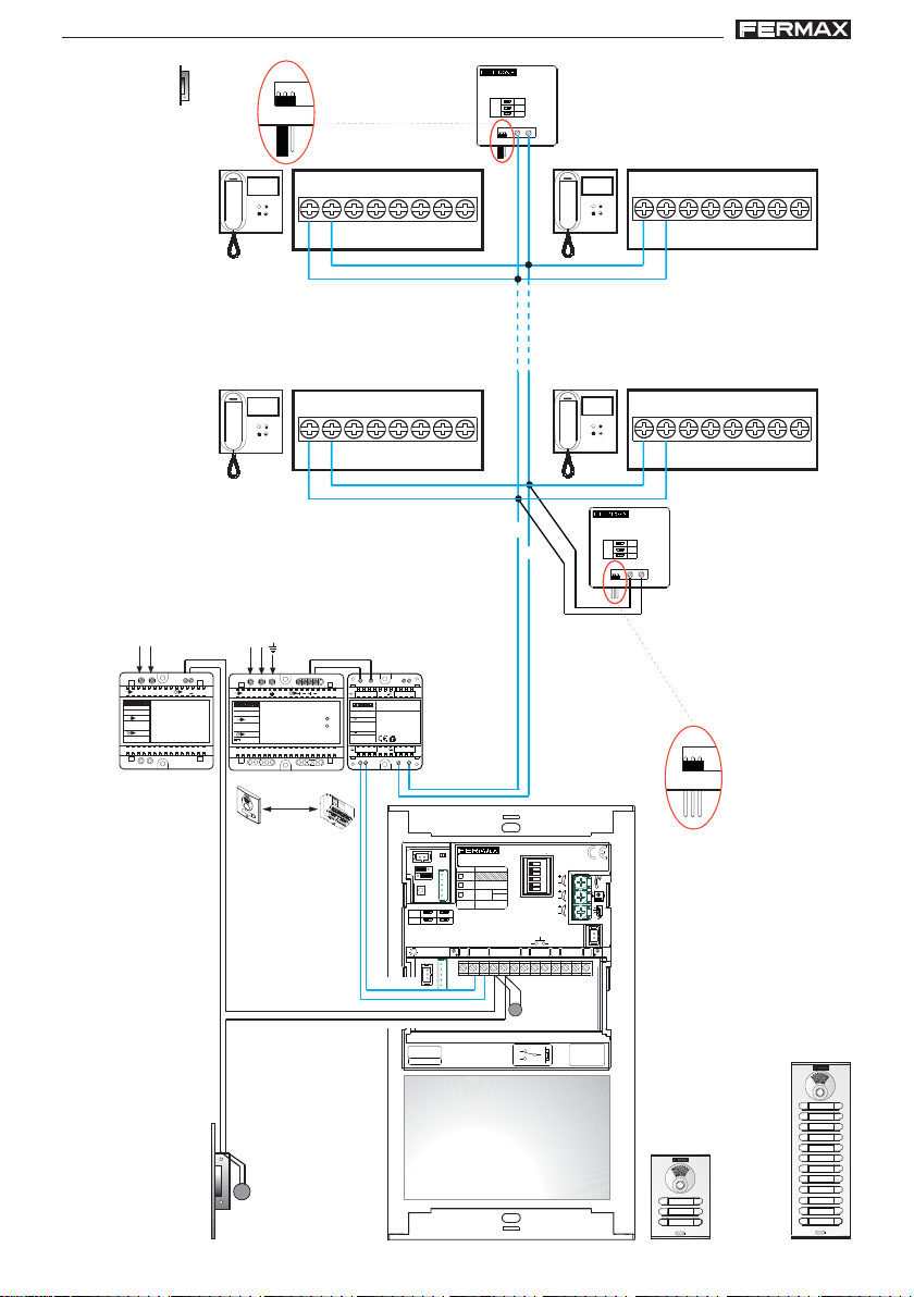
Kit 6-24L & 12 Vac
A
DUOX LINE
ADAPTOR
REF: 3255
JP1
JP1
A
B
C
B
B
in
BinB
in
BinB
in
BinB
18 Vdc
ON
OVERLOAD
M
A
D
E
I
N
S
P
A
I
N
5
0
6
0
H
z
.
5
0
V
A
M
A
X
F
+
.
U
1
8
E
V
N
T
1
E
2
1
V
A
.
5
L
A
I
K
M
1
I
E
T
A
N
T
D
A
I
C
G
I
O
I
T
N
A
L
outBout
outBout
18 Vdc IN
MADE IN SPAIN
REF. 3244
INPUT
18Vdc/2A
OUTPUT
18Vdc/2A
PWR BUS PWR BUS
DUOX POWER
SUPPLY ADAPTER MODULE
Ref. 3244
F1
F1
Vac
230 V
~
INPUT
12Vac
230V ; 0,2 A
~
50-60 Hz
OUTPUT
12 V ; 1,5 A
~
12 Vac
~
~
~
100-240V ; 0,5 A
50-60 Hz
Vac
~
100-240V
~
INPUT
18Vdc
OUTPUT
18 V ; 1,5 A
D. max.
+A F1
-
+A F1
-
PREV BUS
TB
TB
B in
B in
F1
F1
DUOX LINE
ADAPTOR
REF: 3255
JP1
JP1
outBout
in
BinB
outBout
A
B
C
B
B
+A F1
-
+A F1
-
C
TB
TB
Ver tabla
secciones-
distancias
CN9
JP1
JP2
SW1
SW1 PROG
JP1
JP2
ALIMENTACION
POWER SUPPLY
-+
CN9 TAMPER
DL2
PACK
CN1
TYPE
EG
BK
SB
CN1
PL
Nº
LEDS ON
LEDS OFF
TERM OFF
TERM ON
ONE
TO
ONE
BUS
CN3CN2
B
P2
18 Vdc
12 Vac
DUOX VIDEO
EXTENSION
Nº
BK
C
B
AMPLIFICADOR
AMPLIFIER
ON
A
AUDIO
B
C
D
E
F
IDIOMA
LANGUAGE
EXIT
+12
NCNO
BS
NC
C
NO
MIC
18Vdc
+
GND
P1
-
S
VERSION
:
.......
Pag 20
Page 21

DUODUO
X CITYLINE KIT 3-24LX CITYLINE KIT 3-24L
DUO
X CITYLINE KIT 3-24L
DUODUO
X CITYLINE KIT 3-24LX CITYLINE KIT 3-24L
DUODUO
X CITYLINE KIT 3-24LX CITYLINE KIT 3-24L
DUO
X CITYLINE KIT 3-24L
DUODUO
X CITYLINE KIT 3-24LX CITYLINE KIT 3-24L
AMPLIACIONES
Para añadir terminales adicionales en una vivienda (hasta un máximo de 3), se debe
añadir un alimentador + un filtro en dicha vivienda. Distancia máxima, 20 metros de la
troncal al monitor más alejado dentro de la vivienda.
Si se realizan ampliaciones, se deberán revisar las configuraciones de las terminaciones
de línea. Ver instrucciones cod. 97698 Terminación de línea Duox.
F1
~
100-240V
~
INPUT
100-240V ; 0,5 A
~
18Vdc
50-60 Hz
OUTPUT
18 V ; 1,5 A
~
100-240V
~
INPUT
100-240V ; 0,5 A
~
18Vdc
50-60 Hz
OUTPUT
18 V ; 1,5 A
18 Vdc IN
PREV BUS
DUOX POWER
SUPPLY ADAPTER MODULE
MADE IN SPAIN
REF. 3244
ON
INPUT
OVERLOAD
18Vdc/2A
Ref. 3244
OUTPUT
18Vdc/2A
PWR BUS PWR BUS
18 Vdc IN
PREV BUS
DUOX POWER
SUPPLY ADAPTER MODULE
MADE IN SPAIN
REF. 3244
ON
INPUT
OVERLOAD
18Vdc/2A
Ref. 3244
OUTPUT
18Vdc/2A
PWR BUS PWR BUS
in
BinB
outBout
+A F1
-
F1
in
BinB
outBout
+A F1
-
F1
TB
in
BinB
outBout
+A F1
-
F1
TB
in
BinB
outBout
+A F1
-
F1
TB
in
BinB
outBout
TB
-
SW3
+A F1
CN1
TB
F1
~
100-240V
~
INPUT
100-240V ; 0,5 A
~
18Vdc
50-60 Hz
OUTPUT
18 V ; 1,5 A
18 Vdc IN
PREV BUS
DUOX POWER
SUPPLY ADAPTER MODULE
MADE IN SPAIN
REF. 3244
ON
INPUT
OVERLOAD
18Vdc/2A
Ref. 3244
OUTPUT
18Vdc/2A
PWR BUS PWR BUS
in
BinB
outBout
+A F1
-
TB
CN1
SW3
CN1
SW3
Pag 21
Page 22

DUODUO
X CITYLINE KIT 3-24LX CITYLINE KIT 3-24L
DUO
X CITYLINE KIT 3-24L
DUODUO
X CITYLINE KIT 3-24LX CITYLINE KIT 3-24L
DUODUO
X CITYLINE KIT 3-24LX CITYLINE KIT 3-24L
DUO
X CITYLINE KIT 3-24L
DUODUO
X CITYLINE KIT 3-24LX CITYLINE KIT 3-24L
Ref. 2438
REF. 2438
+A -A
-A+A
ACTIVADOR DE LUCES ADS
ADS LIGHT COMMANDER
2A.
Max. 2A
110-240Vac
50-60Hz
F1 2A
Red
110-240Vac
F1
in
BinB
outBout
+A F1
-
TB
110-240Vac
in
BinB
F1
outBout
+A F1
-
TB
Ref. 2040
• •
• "A" , "-":
• •
Conexión Prolongador de llamada ref. 2040 / Activador de Luces y Timbres ref. 2438.
• •
• P: "T" , "-"
• •
Pulsador de llamada puerta vivienda.
CONEXIÓN ABREPUERT AS
12 Vdc
Vac
18 Vdc
-+-+
18 Vdc IN
MADE IN SPAIN
REF. 3244
INPUT
18Vdc/2A
OUTPUT
18Vdc/2A
PWR BUS PWR BUS
PREV BUS
DUOX POWER
SUPPLY FILTER
Ref. 3244
B
B
P
Pag 22
AMPLIFICADOR
DUOX VIDEO
EXTENSION
Nº
C
AMPLIFIER
ON
A
AUDIO
B
C
D
E
F
BK
IDIOMA
LANGUAGE
EXIT
+12
NCNO
BS
NC
C
NO
MIC
18Vdc
+
GND
P1
-
S
VERSION
:
CN9 TAMPER
DL2
CN9
PACK
CN1
JP1
TYPE
EG
JP2
BK
SB
SW1
CN1
PL
Nº
SW1 PROG
JP1
LEDS ON
LEDS OFF
JP2
TERM OFF
TERM ON
B
B
ALIMENTACION
POWER SUPPLY
18 Vdc
-+
ONE
TO
ONE
BUS
CN3CN2
BB
P2
12Vdc
Page 23

DUODUO
X CITYLINE KIT 3-24LX CITYLINE KIT 3-24L
DUO
X CITYLINE KIT 3-24L
DUODUO
X CITYLINE KIT 3-24LX CITYLINE KIT 3-24L
DUODUO
X CITYLINE KIT 3-24LX CITYLINE KIT 3-24L
DUO
X CITYLINE KIT 3-24L
DUODUO
X CITYLINE KIT 3-24LX CITYLINE KIT 3-24L
Ejemplo: Esquema unifilar de DIST ANCIAS MÁXIMAS.
F1 F1
F1 F1
F1 F1
20 m.
Vac
18 Vdc
F1 F1
F1 F1
20 m.
F1 F1
20 m.
-+-+
18 Vdc IN
PREV BUS
DUOX POWER
SUPPLY ADAPTER MODULE
MADE IN SPAIN
REF. 3244
INPUT
Ref. 3244
18Vdc/2A
OUTPUT
18Vdc/2A
PWR BUS PWR BUS
10 m.
20 m.20 m. 20 m.
E
NOTAS Generales de CABLEADO DUOX
DUOX se caracteriza por su flexibilidad en el uso de diferentes tipos de cable. Para un
funcionamiento ideal, se recomienda utilizar cable paralelo de 2x1mm². (Ref. 5925).
Es preferible evitar:
1. Doblar cables (unir 2 pares para aumentar la sección).
2. Utilizar diferentes tipos de cable o cambiar la sección a lo largo de la instalación.
3. Cables sueltos (hilos o cables para instalaciones eléctricas, no dentro de manguera).
4. Cables de diferentes longitudes.
DUOX es un sistema diseñado para la reposición que funciona con el cableado existente en
las instalaciones más antiguas:
• Paralelo (negro-rojo). 0,2mm² mínimo
• UTP CA T-5
• Manguera de varios hilos (por ejemplo, 5 hilos, 6 hilos…etc.)
• Instalaciones 4 + N
Naturalmente, no se pueden tener las mismas prestaciones y flexibilidad en una instalación si
la sección del cable es 0,2mm², en comparación con otra de 1mm².
Pag 23
Page 24

DUODUO
X CITYLINE KIT 3-24LX CITYLINE KIT 3-24L
DUO
X CITYLINE KIT 3-24L
DUODUO
X CITYLINE KIT 3-24LX CITYLINE KIT 3-24L
DUODUO
X CITYLINE KIT 3-24LX CITYLINE KIT 3-24L
DUO
X CITYLINE KIT 3-24L
DUODUO
X CITYLINE KIT 3-24LX CITYLINE KIT 3-24L
TABLAS SECCIONES DIST ANCIAS
Máxima
cantidad TOTAL
F1
D (max)
Máxima Distancia
PLACA-TERMINAL
80
100
de TERMINALES
120m
100m
adicionales (iii)
Fuentes+Filtros
más alejado con
80
100m
por troncal)
por troncal)
(40
(50
80
100
100m
85m
por troncal)
(40
80
85m
por troncal)
por troncal)
(20
(20
60
60
70m
70m
por troncal)
(20
60
70m
F1 F1
UNIDADES UNIDADES
F1
B
PREV BUS
DUOX POWER
SUPPLY ADAPTER MODULE
INPUT
18 Vdc IN
MADE IN SPAIN
REF. 3244
-+-+
Vac
PREV BUS
DUOX POWER
SUPPLY ADAPTER MODULE
18 Vdc IN
MADE IN SPAIN
REF. 3244
-+-+
Vac
A
PREV BUS
DUOX POWER
SUPPLY ADAPTER MODULE
INPUT
18 Vdc IN
MADE IN SPAIN
REF. 3244
-+-+
-+-+
Vac
Vac
A
Máxima cantidad
Ref. 3244
OUTPUT
PWR BUS PWR BUS
18Vdc/2A
18Vdc/2A
Ref. 3244
18 Vdc
Ref. 3244
INPUT
OUTPUT
PWR BUS PWR BUS
18Vdc/2A
18Vdc/2A
Ref. 3244
18 Vdc
Ref. 3244Ref. 3244
OUTPUT
PWR BUS PWR BUS
18Vdc/2A
18Vdc/2A
Ref. 3244
18 Vdc
18 Vdc
1,5 A
18Vdc
(ii)
40 24
de TERMINALES
3,5 A
18Vdc
40m
Fuente/Filtro hasta el
Distancia máxima (B)
T erminal más alejado (ii)
20m
(SIN Abrepuertas) (i)
Distancia máxima (A)
Fuente/Filtro hasta Placa
20m
40 24
40 24
35m
30m
20m
15m
15m
10m
40 24
40m
10m
10m
40 24
40 24
35m
30m
10m
10m
10m
10m
40 24
40 24
40m
35m
10m
10m
10m
10m
40 24
30m
10m
10m
TABLAS SECCIONES DIST ANCIAS - INST ALACIÓN DE KITS DE VIDEO con FIL TRO (de 3 a 24 Líneas)
1 TRONCAL
Pag 24
Distancia máxima (A)
(Placa-Abrepuertas) (i)
Fuente/Filtro hasta Placa
SECCIÓN CABLE
2
2
2
2 x 0,5 mm
2 x 1 mm
2 x 0,2 mm
2
2
2 TRONCALES
2
2 x 0,5 mm
2 x 1 mm
2 x 0,2 mm
2
2
2
2 x 0,5 mm
3 TRONCALES
2 x 1 mm
2 x 0,2 mm
i) Para abrepuertas de 12Vdc y consumo máx. 250mA, alimentado desde el amplificador.
(ii) Cada Fuente+Filtro adicional permite expandir el sistema en distancia y terminales según la tabla.
(iii) Distancias mayores pueden alcanzarse mediante regeneradores.
(
Tabla con TERMINALES (monitores) versión V10.11 y superiores.
Page 25

DUODUO
X CITYLINE KIT 3-24LX CITYLINE KIT 3-24L
DUO
X CITYLINE KIT 3-24L
DUODUO
X CITYLINE KIT 3-24LX CITYLINE KIT 3-24L
DUODUO
X CITYLINE KIT 3-24LX CITYLINE KIT 3-24L
DUO
X CITYLINE KIT 3-24L
DUODUO
X CITYLINE KIT 3-24LX CITYLINE KIT 3-24L
CODIFICACIÓN IDIOMAS. SINTETIZADOR DE VOZ
Pag 25
Page 26

DUODUO
X CITYLINE KIT 3-24LX CITYLINE KIT 3-24L
DUO
X CITYLINE KIT 3-24L
DUODUO
X CITYLINE KIT 3-24LX CITYLINE KIT 3-24L
DUODUO
X CITYLINE KIT 3-24LX CITYLINE KIT 3-24L
DUO
X CITYLINE KIT 3-24L
DUODUO
X CITYLINE KIT 3-24LX CITYLINE KIT 3-24L
SINTETIZADOR DE VOZ. CODIFICACIÓN IDIOMAS (V er tabla).
ON ON ON
5123 4 6
0123
5123 4 6
5
5123 4 6 512 34 6
5123 4 6
5123 4 6 512 34 6 512 34 6
ON ON
5123 4 6 5123 4 6
67
5123 4 6 512 34 6 5123 4 6
11
ON
12 13 14
ON
5123 4 6
5123 4 6
ON ON
5123 4 6
8
ON ON
5123 4 6 512 34 6
16 17 18 19
5123 4 6
5123 4 6
ON ON
5123 4 6 512 34 6
21
ON
5123 4 6
22 23
ON
ON
5123 4 6
ON
5123 4 6
5123 4 6
28
5123 4 6 5123 4 6
O
N
1 2 3 4 5 6
ON
ON
ON ON ON ON ON
10
ON
15
ON
20
ON
25 26 27
ON ON
62 63
ON
5123 4 6
4
5123 4 6
9
ON
5123 4 6
24
ON
5123 4 6
29
CODE
0
1
2
3
4
5
6
7
8
9
10
11
12
13
14
castellano
inglés
francés
holandés/flamenco
alemán
catalán
valenciano
balear
portugués
euskera
gallego
griego
polaco
checo
eslovaco
15
turco
CODE
16
17
18
19
20
21
22
23
24
25
26
27
28
29
30..62
63
DESACTIVADO
Hay posiciones sin idioma: 30...62, (sonará la campana).
(*) IMPORT ANTE
Futuras actualizaciones de idiomas, consultar web Fermax.
Pag 26
chino
persa/farsi
árabe
noruego
finés
sueco
danés
islandés
ruso
italiano
hindi
húngaro
hebreo
croata
Campana
Page 27

DUODUO
X CITYLINE KIT 3-24LX CITYLINE KIT 3-24L
DUO
X CITYLINE KIT 3-24L
DUODUO
X CITYLINE KIT 3-24LX CITYLINE KIT 3-24L
DUODUO
X CITYLINE KIT 3-24LX CITYLINE KIT 3-24L
DUO
X CITYLINE KIT 3-24L
DUODUO
X CITYLINE KIT 3-24LX CITYLINE KIT 3-24L
Sección II - Manual del Usuario
¡Enhorabuena por adquirir un producto de calidad!
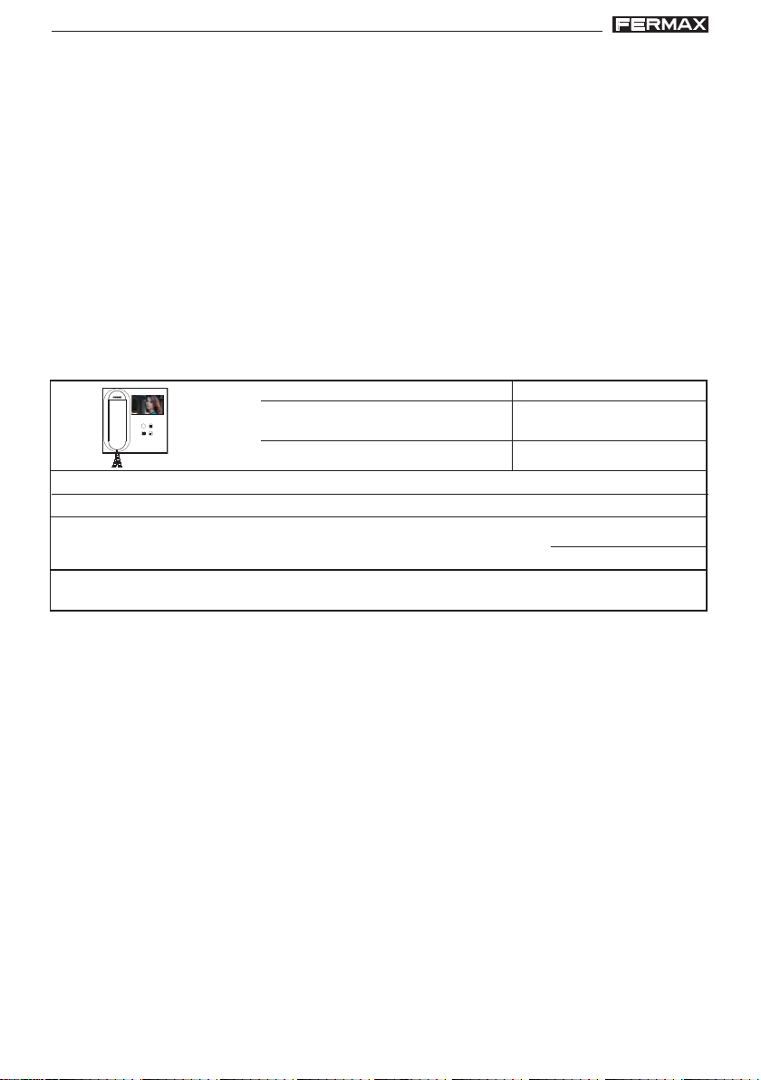
El monitor de videoportero Veo, con pantalla informativa a todo
color para personalización de las funciones de usuario, le
permitirá comunicarse con la placa de calle, ver la persona
que le está llamando y abrirle la puerta de entrada si así lo
desea.
Gracias a su menú en pantalla se incluyen nuevas prestaciones
para la configuración de los parámetros del monitor.
Esperamos disfrute de sus funcionalidades.
www.fermax.com
Pag 27
Page 28

DUODUO
X CITYLINE KIT 3-24LX CITYLINE KIT 3-24L
DUO
X CITYLINE KIT 3-24L
DUODUO
X CITYLINE KIT 3-24LX CITYLINE KIT 3-24L
DUODUO
X CITYLINE KIT 3-24LX CITYLINE KIT 3-24L
DUO
X CITYLINE KIT 3-24L
DUODUO
X CITYLINE KIT 3-24LX CITYLINE KIT 3-24L
MONITOR VEO
F1
F1
Botones
Botón de abrepuertas / llamada a conserje.
· Estando en comunicación con la Placa de Calle (audio solo o video sólo o audio+video),
al pulsar este botón se activa el abrepuertas.
· Con el brazo colgado (monitor en reposo), al pulsar este botón se realiza una llamada al
conserje (si existe conserjería y el monitor esta en modo día o mixto).
Botón Autoencendido.
Conexión con cámara del Bloque o de la Entrada General (función disponible según
tipo de instalación, ver capítulo Funcionamiento: Autoencendido).
Botón F1
F1
Función auxiliar (consulte con su instalador).
Botón Menú: Ajustes y configuración.
· Para acceder al menú de Usuario, desde éste se pueden personalizar los ajustes de
usuario.
- Botones de navegación y pulsadores del monitor
Pulsadores monitor
F1
F1
botones de navegación
Los iconos visualizados en la pantalla (botones de navegación: , , y ), se manejan con
los pulsadores correspondientes ubicados en el monitor
olvemos a la pantalla anterior o stand-by.
: V
: Seleccionamos la opción previa del menú.
: Marcamos la siguiente opción del menú.
: Confirma la selección y activa la función.
Nota: La línea blanca abajo del icono indica en la función en la que nos encontramos. Al pulsar
se selecciona.
Pag 28
Page 29

DUODUO
X CITYLINE KIT 3-24LX CITYLINE KIT 3-24L
DUO
X CITYLINE KIT 3-24L
DUODUO
X CITYLINE KIT 3-24LX CITYLINE KIT 3-24L
DUODUO
X CITYLINE KIT 3-24LX CITYLINE KIT 3-24L
DUO
X CITYLINE KIT 3-24L
DUODUO
X CITYLINE KIT 3-24LX CITYLINE KIT 3-24L
Programación: Pantalla MENÚ USUARIO
Existen las siguientes opciones:
1. Volumen.
2. Modo no molestar
3. F2
4. Configuración.
1
2
3
1. Menú USUARIO: Ajuste volumen melodías.
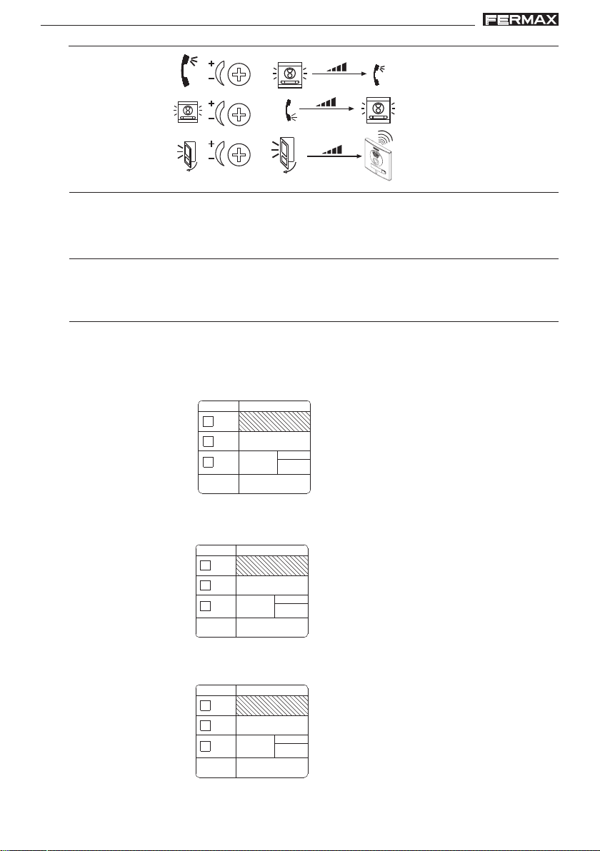
En primer lugar se muestra y se escucha el volumen actual que podrá ir aumentando
o decrementando con los botones correspondientes a las flechas indicadas en pantalla.
2. Menú USUARIO: Modo No molestar (cancelar el tono de llamada).
Función para desactivar el tono de llamada.
4
Cancelado el e l tono de llamada. El led rojo
del monitor parpadea lento cuando esta
opción está activada.
Funcionamiento normal (se escucha la llamada).
Pag 29
Page 30

DUODUO
X CITYLINE KIT 3-24LX CITYLINE KIT 3-24L
DUO
X CITYLINE KIT 3-24L
DUODUO
X CITYLINE KIT 3-24LX CITYLINE KIT 3-24L
DUODUO
X CITYLINE KIT 3-24LX CITYLINE KIT 3-24L
DUO
X CITYLINE KIT 3-24L
DUODUO
X CITYLINE KIT 3-24LX CITYLINE KIT 3-24L
3. Menú USUARIO: Función F2.
La función F2 envía un comando de activación
auxiliar para: relés, decoders...etc. En la pantalla se notificará la acción: F2 OK durante 3
segundos. Esta función sale por defecto en la
pantalla principal del menú de usuario.
(Consulte con su instalador).
4. Menú USUARIO: CONFIGURACIÓN
4.1)
4.2)
4.3)
4.1. Menú USUARIO: MELODÍAS
El monitor permite seleccionar una melodía independiente para la placa y la conserjería.
Dentro de la función Melodías, existen las siguientes opciones:
a) Selección melodía placa
b) Selección melodía conserjería.
4.1.1) Selección melodía placa
Seleccionando esta opción se puede cambiar la melodía que se escuchará en el monitor cuando
se realice una llamada desde la placa de la calle. Una vez seleccionada, muestra y se escucha la
melodía actual, pulsando el botón «+» o «-» se pueden ir seleccionando y escuchando las diferentes melodías disponibles en el monitor. La melodía escogida es la que se escuchará en el monitor
cuando se realice la llamada desde la placa de calle.
Pag 30
1
Page 31

DUODUO
X CITYLINE KIT 3-24LX CITYLINE KIT 3-24L
DUO
X CITYLINE KIT 3-24L
DUODUO
X CITYLINE KIT 3-24LX CITYLINE KIT 3-24L
DUODUO
X CITYLINE KIT 3-24LX CITYLINE KIT 3-24L
DUO
X CITYLINE KIT 3-24L
DUODUO
X CITYLINE KIT 3-24LX CITYLINE KIT 3-24L
4.1.2) Selección melodía conserjería
Seleccionando esta opción se puede cambiar la melodía que se escuchará en el monitor cuando
la conserjería realice una llamada al monitor. Una vez seleccionada esta opción, muestra y se
escucha la melodía actual, pulsando el botón «+» o «-» se pueden ir seleccionando y escuchando
las diferentes melodías disponibles en el monitor. La melodía escogida es la que se escuchará en
el monitor cuando la conserjería realice una llamada al monitor.
2
4.2. Menú USUARIO: RESET
Realiza un reseteo de los parámetros de configuración a los valores por defecto que vienen de
fábrica, conservando la dirección programada para el monitor.
4.3. Menú USUARIO: CÓDIGO QR.
Para acceder a la información relativa al Sistema Duox: manuales, productos relacionados, catálogos, folletos...etc.
Pag 31
Page 32

DUODUO
X CITYLINE KIT 3-24LX CITYLINE KIT 3-24L
DUO
X CITYLINE KIT 3-24L
DUODUO
X CITYLINE KIT 3-24LX CITYLINE KIT 3-24L
DUODUO
X CITYLINE KIT 3-24LX CITYLINE KIT 3-24L
DUO
X CITYLINE KIT 3-24L
DUODUO
X CITYLINE KIT 3-24LX CITYLINE KIT 3-24L
AJUSTES: Video y Audio
Ajuste Video: Brillo - Contraste - Color
El monitor permite realizar los ajustes de brillo, contraste y color mientras se halla recibido
una llamada (sin descolgar) o realizando un autoencendido «cámara»
Funcionamiento: Autoencendido).
Teniendo la imagen de video en la pantalla, realizar una pulsación corta en el botón «MENU»
y aparecerá en pantalla un menú contextual para el ajuste del brillo, contraste y color de la
imagen.
1. Seleccionar los ajustes de contraste, brillo y
color, con los botones correspondientes.
2º. Seleccionar la opción deseada e ir aumentando o decrementando con + y - los ajustes de
video, según la opción escogida.
, (ver capítulo
contraste
color
Pag 32
brillo
Page 33

DUODUO
X CITYLINE KIT 3-24LX CITYLINE KIT 3-24L
DUO
X CITYLINE KIT 3-24L
DUODUO
X CITYLINE KIT 3-24LX CITYLINE KIT 3-24L
DUODUO
X CITYLINE KIT 3-24LX CITYLINE KIT 3-24L
DUO
X CITYLINE KIT 3-24L
DUODUO
X CITYLINE KIT 3-24LX CITYLINE KIT 3-24L
Ajuste Audio
Durante el tiempo que está abierto el canal de audio se puede regular el volumen del audio.
mediante un menú contextual que aparecerá en pantalla. Para realizar el ajuste de audio,
pulsar el botón «MENU» y aparecerá en pantalla un menú contextual para dicho ajuste.
Estando en ajuste de audio, utilizar el + y para ir aumentando o decrementando hasta
obtener la regulación deseada.
FUNCIONAMIENTO
Apertura de puerta
Al recibir una llamada desde la placa de calle, es posible abrir la
puerta en cualquier momento, pulsado el botón
F1
Atender una llamada:
Al presionar el pulsador de llamada en la Placa de Calle se
produce un tono de llamada tanto en la placa de calle como en
el monitor, encendiéndose la pantalla.
Se puede descolgar el brazo y mantener una conversación con la placa
de calle. La comunicación finalizará automáticamente a los 90 segundos o en cualquier momento al colgar el brazo del teléfono.
Si no se establece comunicación (descolgando el brazo) con la placa de
calle, el monitor se apaga automáticamente pasados 30 seg.
.
Autoencendido:
Notas:
- El autoencendido sólo se puede realizar con las placas indicadas. Si no puede realizar el
autoencendido, consulte con su instalador.
- Finalizada cualquier comunicación con una placa, durante 15 segundos si se vuelve a
pulsar el botón de autoencendido se conectará con dicha placa.
Con el monitor en reposo
autoencendido «cámara»
la pantalla la posibilidad de realizar el
autoencendido con diferentes placas
secuencialmente pulsando el boton de
- Placa 0: Es la Placa 0 del Bloque correspondiente al monitor.
- Placa 1: Es la Placa 1 del Bloque correspondiente al monitor.
- Placas G: Es la Placa 0 configurada como En-
trada General.
pulsar el botón
. Se visualiza en
:
Pag 33
Page 34

DUODUO
X CITYLINE KIT 3-24LX CITYLINE KIT 3-24L
DUO
X CITYLINE KIT 3-24L
DUODUO
X CITYLINE KIT 3-24LX CITYLINE KIT 3-24L
DUODUO
X CITYLINE KIT 3-24LX CITYLINE KIT 3-24L
DUO
X CITYLINE KIT 3-24L
DUODUO
X CITYLINE KIT 3-24LX CITYLINE KIT 3-24L
T echnical publication of an informative nature published by FERMAX ELECTRONICA S.A.U.
As part of its constant improvement policy, FERMAX ELECTRONICA reserves the right to
modify the content of this document and the characteristics of the products referred to in it
at any time and without prior notice.
Any modification will be reflected in subsequent editions of this document.
CONGRATULA TIONS ON PURCHASING A QUALITY PRODUCT!
Fermax electronics develops and manufactures renown systems that meet the highest
design and technology standards.
Your FERMAX video door entry system will allow you to communicate with the entry panel,
see who is calling you and open the front door if you wish.
We hope you enjoy its range of functions.
www.fermax.com.
"VIDEO CITYLINE DUOX KIT 3-24L"
Code 97905EI V06_16
Page 2
ENGLISH
Page 35

DUODUO
X CITYLINE KIT 3-24LX CITYLINE KIT 3-24L
DUO
X CITYLINE KIT 3-24L
DUODUO
X CITYLINE KIT 3-24LX CITYLINE KIT 3-24L
DUODUO
X CITYLINE KIT 3-24LX CITYLINE KIT 3-24L
DUO
X CITYLINE KIT 3-24L
DUODUO
X CITYLINE KIT 3-24LX CITYLINE KIT 3-24L
INDEX
SECTION I - INSTALLATION MANUAL ....................................................................... 5
Installing the Power Supply ............................................................................ 6
Installing the outdoor panel ............................................................................ 6
Installing the monitor ...................................................................................... 6
Call panel settings .......................................................................................... 7
Restore default values Reset .......................................................................... 10
- RESET Mapping (call button code)............................................................................10
- Programming Lock Release Times ............................................................................10
- RESET to default parameter values (via keypad) .................................................... 11
Pre-wiring ......................................................................................................... 12
Technical Characteristics ............................................................................... 15
Wiring Diagrams.............................................................................................. 17
SECTION II - USER MANUAL ..................................................................................... 27
Veo Monitor ....................................................................................................... 28
- Buttons ................................................................................................... 28
- Programming: User Menu Screen ....................................................... 29
1. Ring tone volume settings ............................................................ 29
2. Do not disturb mode (cancel call tone) ....................................... 29
3. F2 Function..................................................................................... 30
4. Configuration.................................................................................. 30
4.1) Ring tones .............................................................................. 30
4.1.1) Select panel ring tone.................................................... 30
4.1.2) Select guard unit ring tone ............................................ 31
4.2) Reset ........................................................................................ 31
4.3) QR Code .................................................................................. 31
- Settings: Video and Audio..................................................................... 32
Video: Brightness - Contrast - Colour .......................................... 32
Audio ................................................................................................ 33
- Function................................................................................................... 33
Page 3
Page 36

DUODUO
X CITYLINE KIT 3-24LX CITYLINE KIT 3-24L
DUO
X CITYLINE KIT 3-24L
DUODUO
X CITYLINE KIT 3-24LX CITYLINE KIT 3-24L
DUODUO
X CITYLINE KIT 3-24LX CITYLINE KIT 3-24L
DUO
X CITYLINE KIT 3-24L
DUODUO
X CITYLINE KIT 3-24LX CITYLINE KIT 3-24L
Page 4
Page 37

DUODUO
X CITYLINE KIT 3-24LX CITYLINE KIT 3-24L
DUO
X CITYLINE KIT 3-24L
DUODUO
X CITYLINE KIT 3-24LX CITYLINE KIT 3-24L
DUODUO
X CITYLINE KIT 3-24LX CITYLINE KIT 3-24L
DUO
X CITYLINE KIT 3-24L
DUODUO
X CITYLINE KIT 3-24LX CITYLINE KIT 3-24L
Section I - Installation Manual
Page 5
Page 38

DUODUO
X CITYLINE KIT 3-24LX CITYLINE KIT 3-24L
DUO
X CITYLINE KIT 3-24L
DUODUO
X CITYLINE KIT 3-24LX CITYLINE KIT 3-24L
DUODUO
X CITYLINE KIT 3-24LX CITYLINE KIT 3-24L
DUO
X CITYLINE KIT 3-24L
DUODUO
X CITYLINE KIT 3-24LX CITYLINE KIT 3-24L
INSTALLING THE POWER SUPPL Y
DIN rail Installation - DIN rail Installation
Assembly
ENTRY P ANEL INST ALLA TION
Disassembly
Fastened with screws
M
A
DE
I
N
S
PA
IN
5
0
6
0
H
z
.
5
0
V
A
M
A
F
X
+
.
U
1
8
E
V
N
T
1
E
2
1
A
V
.
5
LIM
A
KIT DIGITAL
1
E
A
N
T
A
C
IO
N
1
3
IA
AR
M
A
C
R
O
L
INST ALLING THE MONITOR
Assembly
1.70m
5.57 feet
2
4
Disassembly
1.60m
5.25 feet
Page 6
2
1
1
B
o
u
t
B
o
u
t
B
i
n
B
i
n
3
1
F
1.60m
5.25 feet
B
o
ut
B
ou
t
B
i
n
B
i
n
2
F1
Page 39

DUODUO
X CITYLINE KIT 3-24LX CITYLINE KIT 3-24L
DUO
X CITYLINE KIT 3-24L
DUODUO
X CITYLINE KIT 3-24LX CITYLINE KIT 3-24L
DUODUO
X CITYLINE KIT 3-24LX CITYLINE KIT 3-24L
DUO
X CITYLINE KIT 3-24L
DUODUO
X CITYLINE KIT 3-24LX CITYLINE KIT 3-24L
PANEL ADJUSTMENTS
C)
A)B)
IDIOMA
LANGUAGE
EXIT
+12
BS
AMPLIFICADOR
AMPLIFIER
ON
A
B
C
D
E
F
-
S
18Vdc
+
AUDIO
GND
H)
I)
J)
MIC
P1
M)
D)
E)
CN9
JP1
JP2
SW1
SW1 PROG
JP1
LEDS ON
JP2
TERM ON
CN1
DL2
LEDS OFF
TERM OFF
ONE
TO
ONE
CN3CN2
CN9 TAMPER
PACK
CN1
TYPE
EG
BK
SB
PL
Nº
BUS
B
P2
DUOX VIDEO
EXTENSION
Nº
BK
C
B
NCNO
F)
A)
G)
ALIMENTACION
POWER SUPPLY
18 Vdc
-+
L)
NC
C
NO
VERSION
:
K)
CN1
Call Extension Module, keypad.
B)
CN9
Tamper Connection (via 2mm male Stocko connector).
C)
DL2
Mode Led:
•Slow flash (1 blink / 1 sec): Inverse or Sequential Programming. See DUOX VIDEO
Advanced Programming Manual cod. 97902.
•Off: standby
D)
MASTER panel:
Programming of home terminals must always be done via the panel activated as
•
MASTER.
• Any installation can only have one MASTER panel at a time, whether a single or
multiple block installation, once configured as a sub-block, block or general entrance.
• A street panel is configured as a MASTER via the SW1 amplifier button. If the SW1
button is pressed 3 times quickly, it is activated as a MASTER panel and a
confirmation tone sounds (beep-beep) after 2 seconds.
• When a panel is selected as MASTER, it notifies the rest of the situation and if
another was previously configured, it would automatically stop being so.
• If there are various blocks in an installation, we recommend using the general
entrance panel as MASTER since it allows you to program all of its telephones/
monitors.
Page 7
Page 40

DUODUO
X CITYLINE KIT 3-24LX CITYLINE KIT 3-24L
DUO
X CITYLINE KIT 3-24L
DUODUO
X CITYLINE KIT 3-24LX CITYLINE KIT 3-24L
DUODUO
X CITYLINE KIT 3-24LX CITYLINE KIT 3-24L
DUO
X CITYLINE KIT 3-24L
DUODUO
X CITYLINE KIT 3-24LX CITYLINE KIT 3-24L
• Once having completed the terminal's configuration, we recommend deactivating
the MASTER panel to avoid accidentally reprogramming terminals.
• The panel deactivates itself from master mode following the same activation
procedure: 3 quick presses of the SW1 button. A deactivation bop sounds after 2
seconds (bop).
Configuration - Programming the Amplifier
The DUOX amplifier can be configured to allow for the operation as a general entrance,
block entrance or sub-block entrance.
• The DUOX system uses 6 digit house terminal addresses.
•These call code digits are organised as follows: BBSSNN:
- BB: indicates the Block number, (from 00 to 99).
- SS: indicates the sub-Block number, (from 00 to 99).
- NN: indicates the sub-Block house number, (from 00 to 99).
You do not have to segregate the installation according to this hierarchy since the
system adapts to the installation's needs.
IMPORT ANT NOTE:
Configuration of the parameters by the installer.
T o configure the Cityline push button panel see ANNEX: V oice assisted configuration
in button panels. Instructions included with this equipment.
You can also configure it by temporarily connecting a keypad ref. 7439, download the
Direct Video Duox Panel Programming Manual, cod. 97900 at www.fermax.com.
E)
Panel Connectors:
• System Connection Terminals:
B,B: DUOX Bus: telephone/monitors power, data, audio and video.
C, NO, NC:Relay contacts,
2A@30Vdc (lock-release connection).
+12: Vdc-250mA output (maximum 500mA for 100 seconds).
BS, -: Entrance Hall Button.
S, - :door sensor input.
+, GND: Not available Future versions.
P1-P2: button connections.
F)
CN2
Individual connection buttons for Cityline continuous profile panel
G)
CN3
OneToOne Module Connection
H)
Page 8
A
B
C
D
E
F
ON
Select language for “open door” message and voice assisted
configuration messages.
See CODING at the end of SECTION I. Installation manual.
Page 41

DUODUO
X CITYLINE KIT 3-24LX CITYLINE KIT 3-24L
DUO
X CITYLINE KIT 3-24L
DUODUO
X CITYLINE KIT 3-24LX CITYLINE KIT 3-24L
DUODUO
X CITYLINE KIT 3-24LX CITYLINE KIT 3-24L
DUO
X CITYLINE KIT 3-24L
DUODUO
X CITYLINE KIT 3-24LX CITYLINE KIT 3-24L
I)
Audio Adjustments
“door open”
J)
MIC
Microphone connection (microphone located in the lower panel profile)
K)
Amplifier Version
L)
Programming data tags. Fill in the fields of the corresponding tags in the completed
programming.
Example 1: Programming as General Entrance and Panel number 3.
TYPE
X
EG
Nº
BK
SB
PL
Nº
Example 2: Programming as Block 1 and Panel number 2.
TYPE
BK
3
Nº
EG
BK
SB
PL
TYPE
01
BK
2
Nº
X
Nº
Example 3: Programming as Sub-Block 2 and Panel number 3, belonging to Block 1.
EG
BK
02
3
BK
01
X
Nº
SB
PL
Page 9
Page 42

DUODUO
X CITYLINE KIT 3-24LX CITYLINE KIT 3-24L
DUO
X CITYLINE KIT 3-24L
DUODUO
X CITYLINE KIT 3-24LX CITYLINE KIT 3-24L
DUODUO
X CITYLINE KIT 3-24LX CITYLINE KIT 3-24L
DUO
X CITYLINE KIT 3-24L
DUODUO
X CITYLINE KIT 3-24LX CITYLINE KIT 3-24L
M)
JP1
JP2 :
Line termination integrated into the amplifier for possible use.
IMPORT ANT NOTE:
Camera focus
T o adjust the camera’s image, see ANNEX: V oice assisted configuration in button p anels.
Instructions included with this equipment.
You can also set it by temporarily connecting a keypad (ref. 7439), or via the duox
programmer (ref. 3254) locally connected.
Download the manuals at: www.fermax.com.
- Direct Video Duox Panels Programming Manual, cod. 97900.
- DUOX Programmer Manual ref 3254, cod. 97731.
DUOX Amplifier Call:
• Panels with an address "0" in each block allow for communication with telephones
when picked-up or with the monitors doing an auto-start with it and when the
communication lines are free. If you do not want this feature do not assign this
address to any panels. The monitors also have the option of an auto-start with
panel 1 in your block and panel 0 of the General Entrance.
• The call is made to the home by pressing the corresponding button.
LEDS ON
lit when the camera is activatedCamera LEDS
LEDS OFF
Always Off
RESTORE DEFAUL T V ALUES: Reset
The DUOX amplifier has a ‘Reset’ function which can be used to restore programmed
default parameters.
RESET Mapping (call button code)
1.- Reset amplifier: remove power.
2.- With the SW1 button pressed, power and maintain the SW1 button for 5 seconds. The
LED will blink quickly to indicate that button mapping has been restored.
Programming Lock Release Times
There are two programmable lock-release activation times:
- Lock-release time set from the residence.
- Lock-release time set from the exit button (connected to the ‘BS’ and ‘-’ terminals).
Notes:
• Values:
- Lock-release time: 01..99 sec. (Default: 03).
- Exit button time: 00..99 sec. (Default: 06). Deactivated: 00.
Page 10
Page 43

DUODUO
X CITYLINE KIT 3-24LX CITYLINE KIT 3-24L
DUO
X CITYLINE KIT 3-24L
DUODUO
X CITYLINE KIT 3-24LX CITYLINE KIT 3-24L
DUODUO
X CITYLINE KIT 3-24LX CITYLINE KIT 3-24L
DUO
X CITYLINE KIT 3-24L
DUODUO
X CITYLINE KIT 3-24LX CITYLINE KIT 3-24L
The door open times can be changed in different ways:
a) Voice assisted Programming
You can also program the opening times via the amplifier's voice assisted configuration.
For more information see ANNEX: Voice assisted configuration in button p anels. Instruc-
tions included with this equipment.
b) Programming from keyboard.
You can also programme lock-release times using a keypad ref. 7439. To enter the
numeric values you must temporarily connect this keypad .
For more information download the DUOX Video Direct Panels Programming Manual, cod.
97900, available at www.fermax.com. The keypad and amplifier connection is explained in
said manual.
c) Electrically manipulating it.
Carry out the following steps:
1. With the power disconnected, short-circuit the terminals amplifier’s "Bs" and "-"
(negative).
2. Maintaining the aforementioned short-circuit, connect the system’s power. The
amplifier will generate as many ‘‘beeps’’ as seconds programmed for the opening
time from the residence.
2.1.If you want to change this value, you must press any call button as often as the
seconds you wish to program.
2.2.If you do not want to change, just wait 10 seconds without pressing any call
button.
3. Thenthe amplifier will "beep" for every secondthe opening time has been pro-
grammed from the exit button.
3.1.If you want to change this value, you must press any call button as often as the
seconds you wish to program.
3.2.If you do not want to change, just wait 10 seconds without pressing any call
button.
4. Exit Programming:
To exit programming mode, wait 10 seconds without pressing any key. A "beep
beep" tone will sound to indicate that you have exited time programming mode.
5º. From that moment you can remove the short-circuit between the terminals “Bs”
and “-” (negative) from the amplifier and you can use the amplifier as normal.
RESET to default parameter values (via keypad)
You can Reset the parameters to the factory default values. For this you must temporarily
connect a keypad (ref. 7439) to enter the numeric values. Download the Direct Video Duox
Panels Programming Manual, cod. 97900, at www.fermax.com.
Page 11
Page 44

DUODUO
X CITYLINE KIT 3-24LX CITYLINE KIT 3-24L
DUO
X CITYLINE KIT 3-24L
DUODUO
X CITYLINE KIT 3-24LX CITYLINE KIT 3-24L
DUODUO
X CITYLINE KIT 3-24LX CITYLINE KIT 3-24L
DUO
X CITYLINE KIT 3-24L
DUODUO
X CITYLINE KIT 3-24LX CITYLINE KIT 3-24L
PRE-WIRING
Call extension module connection (ref. 2008)
CN9
JP1
JP2
JP3
JP2
PREVIOUS
CN1
REF. 2008
CN1
PREVIOUS
18345
2
CN3
7
8
5
6
3
4
1
2
7
6
CN4
CN2
NEXT
SW1
SW1 PROG
JP1
LEDS ON
JP2
TERM ON
ALIMENTACION
POWER SUPPLY
18 Vdc
-+
ARRIBA
UP
ARRIBA
UP
ARRIBA
UP
PACK
CN1
EXTENSION
TYPE
Nº
EG
BK
BK
SB
CN1
PL
Nº
LEDS OFF
TERM OFF
ONE
TO
8
ONE
BUS
CN3CN2
C
B
B
P2
-
+
CP
DUOX VIDEO
CN9 TAMPER
DL2
AMPLIFICADOR
AMPLIFIER
ON
A
AUDIO
B
C
D
E
F
IDIOMA
LANGUAGE
EXIT
18Vdc
+12
NCNO
NC
NO
+
BS
-
S
C
GND
VERSION
MIC
7
P1
:
56
4
2
3
1
Various call extension modules connection (ref. 2008 (more than 8 buttons)
Page 12
9
7
15
3
1
16
.......
10
8
4
2
T o the ADS
CN1
PREVIOUS
18345
CN3
Buttons
(1...8)
1
REF. 2008
2
NEXT - CN2
7
6
CN4
PREVIOUS - CN1PREVIOUS - CN1
PREVIOUS
REF. 2008
18345
2
CN3
Buttons
(9...16)
2
CN2
NEXT
7
6
CN4
Page 45

DUODUO
X CITYLINE KIT 3-24LX CITYLINE KIT 3-24L
DUO
X CITYLINE KIT 3-24L
DUODUO
X CITYLINE KIT 3-24LX CITYLINE KIT 3-24L
DUODUO
X CITYLINE KIT 3-24LX CITYLINE KIT 3-24L
DUO
X CITYLINE KIT 3-24L
DUODUO
X CITYLINE KIT 3-24LX CITYLINE KIT 3-24L
Call extension module connection (ref. 2441)
REF.2441
MODULO EXTENSION 16 LLAMADAS
16 CALL EXTENSION PACK
1312 1614 15
2134 8567119
10
CN9
JP1
JP2
JP3
JP2
SW1
SW1 PROG
JP1
LEDS ON
JP2
TERM ON
ALIMENTACION
POWER SUPPLY
18 Vdc
-+
ARRIBA
UP
ARRIBA
UP
ARRIBA
UP
NCNO
12
10
AMPLIFICADOR
AMPLIFIER
ON
A
AUDIO
B
C
D
E
F
IDIOMA
LANGUAGE
EXIT
18Vdc
+12
+
BS
-
S
NC
C
NO
GND
VERSION
13
MIC
P1
:
11
9
8
7
PACK
EG
BK
SB
PL
BUS
B
-
+
DUOX VIDEO
EXTENSION
Nº
BK
C
B
CN9 TAMPER
DL2
CN1
TYPE
CN1
Nº
LEDS OFF
TERM OFF
ONE
TO
14
ONE
CN3CN2
P2
+
-
CP
ARRIBA
UP
ARRIBA
UP
14
13
12
11
9
10
7
8
5
6
3
4
1
2
ARRIBA
UP
6
4
2
5
3
1
Page 13
Page 46

DUODUO
X CITYLINE KIT 3-24LX CITYLINE KIT 3-24L
DUO
X CITYLINE KIT 3-24L
DUODUO
X CITYLINE KIT 3-24LX CITYLINE KIT 3-24L
DUODUO
X CITYLINE KIT 3-24LX CITYLINE KIT 3-24L
DUO
X CITYLINE KIT 3-24L
DUODUO
X CITYLINE KIT 3-24LX CITYLINE KIT 3-24L
Various call extension modules connection ref. 2441 (more than 16 buttons)
1
REF.2441
SIGUIENTE/NEXT
ANTERIOR/PREVIOUS
To the ADS
31
32
......
19
20
17
18
15
16
3
4
1
2
PACK EXTENSION 16 LLAMADAS
16 EXTENSION CALL PACK
LLAMADAS/CALLS
1
43276510981211 151413 16
Buttons
(1...16)
2
REF.2441
SIGUIENTE/NEXT
ANTERIOR/PREVIOUS
PACK EXTENSION 16 LLAMADAS
16 EXTENSION CALL PACK
LLAMADAS/CALLS
1
43276510981211 151413 16
Buttons
(17...32)
REPLACEMENT OR CHANGE OF MODULES
If for whatever reason you have to change a panel module, remember to not place the microphone
cable inside the panel's profile. We suggest placing them on the modules’ clips. See detail.
Page 14
MIC
Page 47

DUODUO
X CITYLINE KIT 3-24LX CITYLINE KIT 3-24L
DUO
X CITYLINE KIT 3-24L
DUODUO
X CITYLINE KIT 3-24LX CITYLINE KIT 3-24L
DUODUO
X CITYLINE KIT 3-24LX CITYLINE KIT 3-24L
DUO
X CITYLINE KIT 3-24L
DUODUO
X CITYLINE KIT 3-24LX CITYLINE KIT 3-24L
TECHNICAL FEATURES
MIC
Power Supply
Consumption
in standby
IP43 / IK07
Audio power in residence - Entry panel direction
Audio power in entry panel - Residence direction
Operating temperature
Volume can be regulated in both directions
active audio
lighting
Values:
- Lock-release activation time: 01..99 sec. (Default: 03).
- Exit button activation time: 00..99 sec. (Default: 06). Deactivated: 00.
- Maximum conversation time: 90 secs
- Panel type: sub-block/block/general, (default: block).
- Block number: 00..99, (by default: 00).
- Sub-Block number: 00..99, (by default: 00).
- Panel number: 0..9, (by default: 0).
- Door sensor time: 000..250, (by default: 000, not active).
- Opening code: 0000..9999, (by default: not active).
- Programming code: 0000..9999, (by default: 4444).
- MASTER Panel: not active.
18 Vdc
165 mA
275/480 (max) mA
35 mA
1W
0.15 W
[-25º , +55º C]
[-13º, 131º F]
Page 15
Page 48

DUODUO
X CITYLINE KIT 3-24LX CITYLINE KIT 3-24L
DUO
X CITYLINE KIT 3-24L
DUODUO
X CITYLINE KIT 3-24LX CITYLINE KIT 3-24L
DUODUO
X CITYLINE KIT 3-24LX CITYLINE KIT 3-24L
DUO
X CITYLINE KIT 3-24L
DUODUO
X CITYLINE KIT 3-24LX CITYLINE KIT 3-24L
- Monitoring volume: 0..9, (by default: 5).
- Buttons’ sequential programming time after activity has stopped: 60 secs
- Buttons’ inverse programming time after activity has stopped: 300 secs
Capacities:
• Calls from the Button Panel: 99.
• Calls from the Keypad panel:
- Sub-Block: 99.
- Block: 9999.
- General Entrance: 999999.
• Number of Panels:
- General entrances: 10.
- Block: 10.
- Sub-Block: 10.
F1
Operating temperature
Humidity
OSD Screen
Resolution
Dimensions
TFT 4.3”
Power supply
Consumption
Standby
Audio + video
18 Vdc
25 mA
230 mA
[-5, +40 °C]
[0% - 90%]
Hor.: 480 Line TV
Ver.: 272 Line TV
200 x 200 x 46 mm
8” x 8” x 1,8”
Page 16
Page 49

DUODUO
X CITYLINE KIT 3-24LX CITYLINE KIT 3-24L
DUO
X CITYLINE KIT 3-24L
DUODUO
X CITYLINE KIT 3-24LX CITYLINE KIT 3-24L
DUODUO
X CITYLINE KIT 3-24LX CITYLINE KIT 3-24L
DUO
X CITYLINE KIT 3-24L
DUODUO
X CITYLINE KIT 3-24LX CITYLINE KIT 3-24L
Wiring Diagrams
Page 17
Page 50

DUODUO
JP1
JP1
X CITYLINE KIT 3-24LX CITYLINE KIT 3-24L
DUO
X CITYLINE KIT 3-24L
DUODUO
X CITYLINE KIT 3-24LX CITYLINE KIT 3-24L
DUODUO
X CITYLINE KIT 3-24LX CITYLINE KIT 3-24L
DUO
X CITYLINE KIT 3-24L
DUODUO
X CITYLINE KIT 3-24LX CITYLINE KIT 3-24L
WIRING
Kit 3L & 12 Vac
A
DUOX LINE
ADAPTOR
REF: 3255
JP1
JP1
A
B
C
B
B
in
BinB
F1
outBout
+A F1
-
TB
in
BinB
C
outBout
in
BinB
outBout
A
B
C
B
B
F1
F1
Vac
230 V
~
INPUT
12Vac
230V ; 0,2 A
~
50-60 Hz
OUTPUT
12 V ; 1,5 A
~
Vac
12 Vac
~
~
~
100-240V
~
INPUT
100-240V ; 0,5 A
~
50-60 Hz
OUTPUT
18 V ; 1,5 A
sections-distances
18Vdc
D. max.
See table
18 Vdc
ON
OVERLOAD
M
A
D
E
I
N
S
P
A
I
N
5
0
6
0
H
z
.
5
0
V
A
M
A
F
+
X
.
U
1
8
E
V
N
T
1
E
2
1
V
A
.
5
L
A
I
K
M
1
I
E
T
A
N
T
D
A
I
C
G
I
O
I
T
N
A
L
18 Vdc IN
SUPPLY ADAPTER MODULE
MADE IN SPAIN
REF. 3244
INPUT
18Vdc/2A
Ref. 3244
OUTPUT
18Vdc/2A
PWR BUS PWR BUS
DUOX POWER
PREV BUS
DUOX VIDEO
CN9 TAMPER
DL2
CN9
PACK
CN1
JP1
JP2
SW1 PROG
JP1
JP2
SW1
EXTENSION
TYPE
Nº
EG
BK
BK
SB
CN1
PL
Nº
LEDS ON
LEDS OFF
TERM OFF
TERM ON
ONE
TO
ONE
BUS
CN3CN2
C
B
B
P2
B in
B in
DUOX LINE
ADAPTOR
REF: 3255
JP1
JP1
AMPLIFICADOR
AMPLIFIER
ON
A
AUDIO
B
C
D
E
F
IDIOMA
LANGUAGE
EXIT
+12
NCNO
BS
MIC
18Vdc
+
GND
P1
-
S
+A F1
-
+A F1
-
TB
TB
NC
VERSION
ALIMENTACION
POWER SUPPLY
18 Vdc
-+
ARRIBA
UP
ARRIBA
UP
ARRIBA
12 Vac
UP
NO
+
CP
+
CP
+
CP
:
C
Page 18
Page 51

DUODUO
JP1
JP1
X CITYLINE KIT 3-24LX CITYLINE KIT 3-24L
DUO
X CITYLINE KIT 3-24L
DUODUO
X CITYLINE KIT 3-24LX CITYLINE KIT 3-24L
DUODUO
X CITYLINE KIT 3-24LX CITYLINE KIT 3-24L
DUO
X CITYLINE KIT 3-24L
DUODUO
X CITYLINE KIT 3-24LX CITYLINE KIT 3-24L
Kit 4-5L & 12 V ac
A
DUOX LINE
ADAPTOR
REF: 3255
JP1
JP1
A
B
C
B
B
in
BinB
F1
outBout
+A F1
-
TB
in
BinB
F1
Vac
230 V
~
INPUT
12Vac
230V ; 0,2 A
~
50-60 Hz
OUTPUT
12 V ; 1,5 A
~
Vac
12 Vac
~
~
~
100-240V
~
INPUT
100-240V ; 0,5 A
~
50-60 Hz
OUTPUT
18 V ; 1,5 A
sections-distances
18Vdc
D. max.
See table
18 Vdc
ON
OVERLOAD
MADE IN SPAIN
REF. 3244
M
A
D
E
I
N
S
P
A
I
N
5
0
6
0
H
z
.
5
0
V
A
M
A
X
F
+
.
U
1
8
E
V
N
T
1
E
2
1
V
A
.
5
L
A
I
K
M
1
I
E
T
A
N
T
D
A
I
C
G
I
O
I
T
N
A
L
18 Vdc IN
DUOX POWER
SUPPLY ADAPTER MODULE
INPUT
18Vdc/2A
Ref. 3244
OUTPUT
18Vdc/2A
PWR BUS PWR BUS
PREV BUS
CN9
JP1
JP2
SW1
SW1 PROG
JP1
JP2
ALIMENTACION
POWER SUPPLY
-+
ARRIBA
UP
ARRIBA
UP
ARRIBA
UP
ARRIBA
UP
ARRIBA
UP
B in
B in
DUOX LINE
ADAPTOR
REF: 3255
JP1
JP1
AMPLIFICADOR
DUOX VIDEO
EXTENSION
B
AMPLIFIER
ON
A
AUDIO
Nº
B
C
D
E
F
BK
IDIOMA
LANGUAGE
EXIT
18Vdc
+12
+
GND
NCNO
BS
-
S
C
NC
VERSION
C
NO
C
MIC
P1
:
CN9 TAMPER
DL2
PACK
CN1
TYPE
EG
BK
SB
CN1
PL
Nº
LEDS ON
LEDS OFF
TERM OFF
TERM ON
ONE
TO
ONE
BUS
CN3CN2
B
P2
18 Vdc
+
CP
+
CP
+
CP
+
CP
+
CP
outBout
A
B
C
B
B
12 Vac
+A F1
-
TB
Page 19
Page 52

DUODUO
JP1
JP1
X CITYLINE KIT 3-24LX CITYLINE KIT 3-24L
DUO
X CITYLINE KIT 3-24L
DUODUO
X CITYLINE KIT 3-24LX CITYLINE KIT 3-24L
DUODUO
X CITYLINE KIT 3-24LX CITYLINE KIT 3-24L
DUO
X CITYLINE KIT 3-24L
DUODUO
X CITYLINE KIT 3-24LX CITYLINE KIT 3-24L
Kit 6-24L & 12 Vac
A
DUOX LINE
ADAPTOR
REF: 3255
JP1
JP1
A
B
C
B
B
in
BinB
in
BinB
in
BinB
18 Vdc
ON
OVERLOAD
M
A
D
E
I
N
S
P
A
I
N
5
0
6
0
H
z
.
5
0
V
A
M
A
X
F
+
.
U
1
8
E
V
N
T
1
E
2
1
V
A
.
5
L
A
I
K
M
1
I
E
T
A
N
T
D
A
I
C
G
I
O
I
T
N
A
L
outBout
outBout
18 Vdc IN
MADE IN SPAIN
REF. 3244
INPUT
18Vdc/2A
OUTPUT
18Vdc/2A
PWR BUS PWR BUS
DUOX POWER
SUPPLY ADAPTER MODULE
Ref. 3244
F1
F1
Vac
230 V
~
INPUT
12Vac
230V ; 0,2 A
~
50-60 Hz
OUTPUT
12 V ; 1,5 A
~
12 Vac
~
~
~
100-240V ; 0,5 A
50-60 Hz
Vac
~
100-240V
~
INPUT
18Vdc
OUTPUT
18 V ; 1,5 A
D. max.
+A F1
-
+A F1
-
PREV BUS
TB
TB
B in
B in
F1
F1
DUOX LINE
ADAPTOR
REF: 3255
JP1
JP1
outBout
in
BinB
outBout
A
B
C
B
B
+A F1
-
+A F1
-
C
TB
TB
See table
sections-distances
CN9
JP1
JP2
SW1
SW1 PROG
JP1
JP2
ALIMENTACION
POWER SUPPLY
-+
CN9 TAMPER
DL2
PACK
CN1
TYPE
EG
BK
SB
CN1
PL
Nº
LEDS ON
LEDS OFF
TERM OFF
TERM ON
ONE
TO
ONE
BUS
CN3CN2
B
P2
18 Vdc
12 Vac
EXTENSION
B
Nº
BK
C
DUOX VIDEO
IDIOMA
LANGUAGE
EXIT
+12
NCNO
BS
NC
C
NO
AMPLIFICADOR
AMPLIFIER
ON
A
B
C
D
E
F
-
S
AUDIO
MIC
18Vdc
+
GND
P1
VERSION
:
.......
Page 20
Page 53

DUODUO
X CITYLINE KIT 3-24LX CITYLINE KIT 3-24L
DUO
X CITYLINE KIT 3-24L
DUODUO
X CITYLINE KIT 3-24LX CITYLINE KIT 3-24L
DUODUO
X CITYLINE KIT 3-24LX CITYLINE KIT 3-24L
DUO
X CITYLINE KIT 3-24L
DUODUO
X CITYLINE KIT 3-24LX CITYLINE KIT 3-24L
EXTENSIONS
To add additional terminals in a home (a maximum of 3) you must add a power source +
a filter for each home. Distancia máxima, 20 metros de la troncal al monitor más alejado
dentro de la vivienda.
If expanded, the configurations of the line’s terminations must be checked.
See instructions cod. 97698 Duox Line Termination.
F1
~
100-240V
~
INPUT
100-240V ; 0,5 A
~
18Vdc
50-60 Hz
OUTPUT
18 V ; 1,5 A
~
100-240V
~
INPUT
100-240V ; 0,5 A
~
18Vdc
50-60 Hz
OUTPUT
18 V ; 1,5 A
18 Vdc IN
PREV BUS
DUOX POWER
SUPPLY ADAPTER MODULE
MADE IN SPAIN
REF. 3244
ON
INPUT
OVERLOAD
18Vdc/2A
Ref. 3244
OUTPUT
18Vdc/2A
PWR BUS PWR BUS
18 Vdc IN
PREV BUS
DUOX POWER
SUPPLY ADAPTER MODULE
MADE IN SPAIN
REF. 3244
ON
INPUT
OVERLOAD
18Vdc/2A
Ref. 3244
OUTPUT
18Vdc/2A
PWR BUS PWR BUS
in
BinB
outBout
+A F1
-
F1
in
BinB
outBout
+A F1
-
F1
TB
in
BinB
outBout
+A F1
-
F1
TB
in
BinB
outBout
+A F1
-
F1
TB
in
BinB
outBout
TB
SW3
+A F1
-
TB
CN1
F1
~
100-240V
~
INPUT
100-240V ; 0,5 A
~
18Vdc
50-60 Hz
OUTPUT
18 V ; 1,5 A
18 Vdc IN
PREV BUS
DUOX POWER
SUPPLY ADAPTER MODULE
MADE IN SPAIN
REF. 3244
ON
INPUT
OVERLOAD
18Vdc/2A
Ref. 3244
OUTPUT
18Vdc/2A
PWR BUS PWR BUS
in
BinB
outBout
+A F1
-
TB
CN1
SW3
CN1
SW3
Page 21
Page 54

DUODUO
X CITYLINE KIT 3-24LX CITYLINE KIT 3-24L
DUO
X CITYLINE KIT 3-24L
DUODUO
X CITYLINE KIT 3-24LX CITYLINE KIT 3-24L
DUODUO
X CITYLINE KIT 3-24LX CITYLINE KIT 3-24L
DUO
X CITYLINE KIT 3-24L
DUODUO
X CITYLINE KIT 3-24LX CITYLINE KIT 3-24L
Ref. 2438
REF. 2438
+A -A
-A+A
ACTIVADOR DE LUCES ADS
ADS LIGHT COMMANDER
2A.
Max. 2A
110-240Vac
50-60Hz
F1 2A
Red
110-240Vac
F1
in
BinB
outBout
+A F1
-
110-240Vac
in
BinB
TB
F1
outBout
Ref. 2040
• •
• "A" , "-":
• •
Call Extension connection ref. 2040 / Light and doorbell activator ref. 2438.
• •
• P: "T" , "-"
• •
Residence Call Button
DOOR LOCK-RELEASE CONNECTION
12 Vdc
Vac
18 Vdc
-+-+
18 Vdc IN
MADE IN SPAIN
REF. 3244
INPUT
18Vdc/2A
OUTPUT
18Vdc/2A
PWR BUS PWR BUS
PREV BUS
DUOX POWER
SUPPLY FILTER
Ref. 3244
B
B
+A F1
-
P
TB
Page 22
AMPLIFICADOR
DUOX VIDEO
EXTENSION
Nº
C
AMPLIFIER
ON
A
AUDIO
B
C
D
E
F
BK
IDIOMA
LANGUAGE
EXIT
+12
NCNO
BS
-
NC
C
NO
MIC
18Vdc
+
GND
P1
S
VERSION
:
CN9 TAMPER
DL2
CN9
PACK
CN1
JP1
TYPE
EG
JP2
BK
SB
SW1
CN1
PL
Nº
SW1 PROG
JP1
LEDS ON
LEDS OFF
JP2
TERM OFF
TERM ON
B
B
ALIMENTACION
POWER SUPPLY
18 Vdc
-+
ONE
TO
ONE
BUS
CN3CN2
BB
P2
12Vdc
Page 55

DUODUO
X CITYLINE KIT 3-24LX CITYLINE KIT 3-24L
DUO
X CITYLINE KIT 3-24L
DUODUO
X CITYLINE KIT 3-24LX CITYLINE KIT 3-24L
DUODUO
X CITYLINE KIT 3-24LX CITYLINE KIT 3-24L
DUO
X CITYLINE KIT 3-24L
DUODUO
X CITYLINE KIT 3-24LX CITYLINE KIT 3-24L
Example: Single-row diagram of MAXIMUM DISTANCES
F1 F1
F1 F1
F1 F1
20 m.
Vac
18 Vdc
F1 F1
F1 F1
20 m.
F1 F1
20 m.
-+-+
18 Vdc IN
PREV BUS
DUOX POWER
SUPPLY ADAPTER MODULE
MADE IN SPAIN
REF. 3244
INPUT
Ref. 3244
18Vdc/2A
OUTPUT
18Vdc/2A
PWR BUS PWR BUS
10 m.
20 m.20 m. 20 m.
General NOTES DUOX WIRING
DUOX is characterized by its flexibility in the use of different cable types. For ideal operation,
it is recommended to use 2x1mm² parallel cable. (Ref. 5925).
It is preferable to avoid:
1. Doubling cables (joining 2 pairs to increase section).
2. Using different cable type or changing the section throughout the installation.
3. Loose wires (electrical installation wiring not within its hose).
4. Different length cables.
As Duox is a system designed for replacement, it works with the existing wiring in older
installations:
Parallel (black-red). 0.2mm² minimum
• UTP CA T -5
• Hose with several wires (for example, 5 wires, 6 wires…etc.)
• 4+N Installations
Naturally, we cannot access an installation offering the same features and flexibility of
installation when the cable section is 0.2mm² as when it is 1mm².
Page 23
Page 56

DUODUO
X CITYLINE KIT 3-24LX CITYLINE KIT 3-24L
DUO
X CITYLINE KIT 3-24L
DUODUO
X CITYLINE KIT 3-24LX CITYLINE KIT 3-24L
DUODUO
X CITYLINE KIT 3-24LX CITYLINE KIT 3-24L
DUO
X CITYLINE KIT 3-24L
DUODUO
X CITYLINE KIT 3-24LX CITYLINE KIT 3-24L
TABLES SECTIONS DIST ANCES
TOT A L number
F1
D (max)
Maximum Distance
100
of TERMINALS
120m
+ Filters (iii)
TERMINAL with
PANEL- furthest
additional Sources
80
80
100m
100m
per riser)
per riser)
(40
(50
80
100
100m
85m
per riser)
(40
80
85m
per riser)
per riser)
(20
(20
60
60
70m
70m
per riser)
(20
60
70m
UNITS UNITS
F1 F1
Maximum number
of TERMINALS(ii)
F1
1,5 A
18Vdc
3,5 A
18Vdc
40 24
40 24
40 24
40 24
40 24
40 24
40 24
40 24
40 24
B
PREV BUS
DUOX POWER
Ref. 3244
SUPPLY ADAPTER MODULE
INPUT
OUTPUT
PWR BUS PWR BUS
18Vdc/2A
18Vdc/2A
18 Vdc IN
MADE IN SPAIN
REF. 3244
Ref. 3244
-+-+
18 Vdc
Vac
PREV BUS
DUOX POWER
Ref. 3244
SUPPLY ADAPTER MODULE
INPUT
OUTPUT
PWR BUS PWR BUS
18Vdc/2A
18Vdc/2A
18 Vdc IN
MADE IN SPAIN
REF. 3244
Ref. 3244
-+-+
18 Vdc
Vac
Furthest terminal (ii)
Maximum distance (B)
Source/Filter up to Panel
A
Maximum distance (A)
(WITHOUT lock release)
PREV BUS
DUOX POWER
Ref. 3244Ref. 3244
SUPPLY ADAPTER MODULE
INPUT
OUTPUT
PWR BUS PWR BUS
18Vdc/2A
18Vdc/2A
18 Vdc IN
MADE IN SPAIN
REF. 3244
-+-+
-+-+
18 Vdc
18 Vdc
Vac
Vac
Source/Filter up to Panel
Ref. 3244
A
40m
35m
(i)
20m
20m
20m
15m
30m
15m
10m
40m
35m
10m
10m
10m
10m
30m
10m
10m
40m
35m
10m
10m
10m
10m
30m
10m
10m
DISTANCE SECTION T ABLE - VIDEO KIT INST ALLA TION with FIL TER (3 and 24 Lines)
1 RISER
Page 24
Maximum distance (A)
(Panel-Lock release) (i)
Source/Filter up to Panel
CABLE SECTION
2
2
2
2 x 0,5 mm
2 x 1 mm
2 x 0,2 mm
2
2
2 x 0,5 mm
2 RISERS
2 x 1 mm
2
2 x 0,2 mm
2
2
3 RISERS
2 x 1 mm
2
2 x 0,5 mm
2 x 0,2 mm
(i) For 12Vdc door lock max. 250mA supplied from amplifier.
(ii) Each additional PSU-Filter allow to expand the system in distance and terminals according to the table.
(iii) Longer distances can be reached via regenerators.
Table with TERMINALS (monitors) version V10.11 and greater.
Page 57

DUODUO
X CITYLINE KIT 3-24LX CITYLINE KIT 3-24L
DUO
X CITYLINE KIT 3-24L
DUODUO
X CITYLINE KIT 3-24LX CITYLINE KIT 3-24L
DUODUO
X CITYLINE KIT 3-24LX CITYLINE KIT 3-24L
DUO
X CITYLINE KIT 3-24L
DUODUO
X CITYLINE KIT 3-24LX CITYLINE KIT 3-24L
LANGUAGE CODING . VOICE SYNTHESIZER
Page 25
Page 58

DUODUO
X CITYLINE KIT 3-24LX CITYLINE KIT 3-24L
DUO
X CITYLINE KIT 3-24L
DUODUO
X CITYLINE KIT 3-24LX CITYLINE KIT 3-24L
DUODUO
X CITYLINE KIT 3-24LX CITYLINE KIT 3-24L
DUO
X CITYLINE KIT 3-24L
DUODUO
X CITYLINE KIT 3-24LX CITYLINE KIT 3-24L
VOICE SYNTHESISER LANGUAGE ENCODING (See table).
ON ON ON
5123 4 6
0123
5123 4 6
5
5123 4 6 512 34 6
5123 4 6
5123 4 6 512 34 6 512 34 6
ON ON
5123 4 6 5123 4 6
67
5123 4 6 512 34 6 5123 4 6
11
ON
12 13 14
ON
5123 4 6
5123 4 6
ON ON
8
ON ON
16 17 18 19
5123 4 6
5123 4 6
ON ON
5123 4 6 512 34 6
21
ON
5123 4 6
22 23
ON
ON
ON
5123 4 6
28
5123 4 6 5123 4 6
O
N
1 2 3 4 5 6
ON
ON
ON ON ON ON ON
10
ON
15
ON
20
ON
25 26 27
ON ON
62 63
ON
4
5123 4 6
9
5123 4 6 512 34 6
ON
5123 4 6
24
ON
5123 4 6
5123 4 6
29
5123 4 6
5123 4 6
5123 4 6
CODE
0
1
2
3
4
5
6
7
8
9
10
11
12
13
14
15
Spanish
English
French
Dutch/Flemish
German
Catalan
Valencian
Balearic
Portuguese
Basque
Galician
Greek
Polish
Czech
Slovak
Turkish
CODE
16
17
18
19
20
21
22
23
24
25
26
27
28
29
30..62
63
Chinese
Persian/Farsi
Arabic
Norwegian
Finnish
Swedish
Danish
Icelandic
Russian
Italian
Hindi
Hungarian
Hebrew
Croatian
Bell
DEACTIV ATED
There are positions without a language: 30...62, (the bell will sound).
(*) IMPORTANT
Future language updates, see Fermax website
Page 26
Page 59

DUODUO
X CITYLINE KIT 3-24LX CITYLINE KIT 3-24L
DUO
X CITYLINE KIT 3-24L
DUODUO
X CITYLINE KIT 3-24LX CITYLINE KIT 3-24L
DUODUO
X CITYLINE KIT 3-24LX CITYLINE KIT 3-24L
DUO
X CITYLINE KIT 3-24L
DUODUO
X CITYLINE KIT 3-24LX CITYLINE KIT 3-24L
Section II - User Manual
Congratulations on purchasing this quality product!
The Veo Monitor, with an informative, full colour screen allows
you to communicate with the entry panel, see the caller and
open the entrance door if you wish.
Thanks to its on-screen menu new features are included for
configuring the monitor’s parameters.
We hope you enjoy its range of functions.
www.fermax.com.
Page 27
Page 60

DUODUO
F1
X CITYLINE KIT 3-24LX CITYLINE KIT 3-24L
DUO
X CITYLINE KIT 3-24L
DUODUO
X CITYLINE KIT 3-24LX CITYLINE KIT 3-24L
DUODUO
X CITYLINE KIT 3-24LX CITYLINE KIT 3-24L
DUO
X CITYLINE KIT 3-24L
DUODUO
X CITYLINE KIT 3-24LX CITYLINE KIT 3-24L
VEO MONITOR
F1
F1
Buttons
Lock Releases / Call Guard Unit Button.
· While in conversation with the Street Panel (only audio, only video or audio+video), pressing
it will activate the open door lock-release.
· When you press this button with the receiver hung-up (standby) a call will be made to the guard
unit (a guard unit exists and it is in day or mixed mode).
Auto-start button.
Connection with the Block's or General Entrance's camera (depending on availability in
the installation, see Operations chapter: Auto-start).
F1 Button
F1
Auxiliary function, (contact your installer).
Button Menu: Adjustments and configuration.
·
To access the User menu, from this screen you can personalise the user settings.
- Navigation buttons and monitor buttons
Monitor buttons
F1
Navigation buttons
The icons viewed on the screen (navigation buttons: , , and ), are managed with the
corresponding buttons located on the monitor
: Return to the previous screen or stand-by.
: Select the previous menu option.
: Mark the following menu option.
: Confirm the selection and activate the function.
Notice: The white line below the icon indicates the function you are currently in. Upon pressing
it is selected.
Page 28
Page 61

DUODUO
X CITYLINE KIT 3-24LX CITYLINE KIT 3-24L
DUO
X CITYLINE KIT 3-24L
DUODUO
X CITYLINE KIT 3-24LX CITYLINE KIT 3-24L
DUODUO
X CITYLINE KIT 3-24LX CITYLINE KIT 3-24L
DUO
X CITYLINE KIT 3-24L
DUODUO
X CITYLINE KIT 3-24LX CITYLINE KIT 3-24L
Programming: USER MENU Screen
There are the following options:
1. Volume
2. Do not disturb mode
3. F2
4. Configuration
1
2
3
1. USER Menu: Adjust ring tone volume
First of all you see and hear the current volume which can be increased or decreased with the
corresponding arrow buttons indicated on the screen.
2. USER Menu: Do not disturb mode (cancel call tone).
Function for deactivating the call tone.
4
Cancel the call tone. The monitor's red LED
blinks slowly when this option is activated.
Normal function (the call is heard).
Page 29
Page 62

DUODUO
X CITYLINE KIT 3-24LX CITYLINE KIT 3-24L
DUO
X CITYLINE KIT 3-24L
DUODUO
X CITYLINE KIT 3-24LX CITYLINE KIT 3-24L
DUODUO
X CITYLINE KIT 3-24LX CITYLINE KIT 3-24L
DUO
X CITYLINE KIT 3-24L
DUODUO
X CITYLINE KIT 3-24LX CITYLINE KIT 3-24L
3. USER Menu: F2 Function.
The F2 function sends an auxiliary activation
command for: relays, decoders...etc. The
screen notifies of the action: F2 OK for 3
seconds. This function is the default on the
main screen of the user menu.
(Ask your installer).
4. USER Menu: CONFIGURA TION
4.1)
4.2)
4.3)
4.1. USER Menu: RING TONES
The monitor allows you to select a ring tone independently for the panel and guard unit.
Within the Ring tone function, there are the following options:
a) Select panel ring tone
b) Select guard unit ring tone
4.1.1) Select panel ring tone
Selecting this option you can change the ring tone that is heard on the monitor when you make a call
from the street panel. Once selected, it displays and sounds the current ring tone; pressing the "+" or
"-" button you can select and listen to the different available ring tones on the monitor. The ring tone
selected is what is heard on the monitor when you make a call from the street panel.
Page 30
1
Page 63

DUODUO
X CITYLINE KIT 3-24LX CITYLINE KIT 3-24L
DUO
X CITYLINE KIT 3-24L
DUODUO
X CITYLINE KIT 3-24LX CITYLINE KIT 3-24L
DUODUO
X CITYLINE KIT 3-24LX CITYLINE KIT 3-24L
DUO
X CITYLINE KIT 3-24L
DUODUO
X CITYLINE KIT 3-24LX CITYLINE KIT 3-24L
4.1.2) Select guard unit ring tone
Selecting this option you can change the ring tone that is heard on the monitor when the guard unit
makes a call to a monitor. Once this option is selected, it displays and sounds the current ring tone,
pressing the "+" or "-" button you can select and listen to the different available ring tones on the
monitor. The selected ring tone is what is heard on the monitor when the guard unit makes a call to
a monitor.
2
4.2. USER Menu: RESET
Perform a reset of the configuration parameters to the default values, maintaining the monitor's
programmed address.
4.3. USER Menu: QR CODE.
To access the information relative to the Duox System: manuals, related products, catalogues,
brochures...etc.
Page 31
Page 64

DUODUO
X CITYLINE KIT 3-24LX CITYLINE KIT 3-24L
DUO
X CITYLINE KIT 3-24L
DUODUO
X CITYLINE KIT 3-24LX CITYLINE KIT 3-24L
DUODUO
X CITYLINE KIT 3-24LX CITYLINE KIT 3-24L
DUO
X CITYLINE KIT 3-24L
DUODUO
X CITYLINE KIT 3-24LX CITYLINE KIT 3-24L
SETTINGS: Video and Audio
Video adjustments: Brightness - Contrast - Colour
The monitor allows you to adjust brightness, contrast and colour while you have received a
call (without hanging up) or when performing an auto-start "camera" , (see Functions
chapter: Auto-start).
With the video image on the screen, short-press the “MENU” button and a menu appears on
the screen to adjust the image's brightness, contrast and colour.
1. Select the contrast, brightness and colour
settings with the corresponding buttons.
2. Select the desired option and increase or decrease the video settings with the + and buttons according to the selected option.
Contrast
Colour
Page 32
Brightness
Page 65

DUODUO
X CITYLINE KIT 3-24LX CITYLINE KIT 3-24L
DUO
X CITYLINE KIT 3-24L
DUODUO
X CITYLINE KIT 3-24LX CITYLINE KIT 3-24L
DUODUO
X CITYLINE KIT 3-24LX CITYLINE KIT 3-24L
DUO
X CITYLINE KIT 3-24L
DUODUO
X CITYLINE KIT 3-24LX CITYLINE KIT 3-24L
Audio settings
While the audio channel is open the audio's volume can be regulated via a contextual menu
on the screen. In order to set the audio, press MENU and a menu screen appears for this
setting.
In the audio settings, use the + and - buttons to
increase or decrease until reaching the desired
setting.
FUNCTION
Door lock-release
When a call is received from the entry panel, you can open the door
at any time, by pressing the button
F1
Answering a call:
When the call button on the Entry Panel is pressed a call tone
sounds both on the panel and on the monitor, causing the screen
to start up.
Y ou can pick up the phone receiver and have a conversation with the street
panel. The communication will automatically terminate after 90
seconds, or at any time by hanging up the phone.
If communication is not established (picking-up the receiver) with the entry
panel, the monitor will automatically turn off after 30 seconds.
Auto-Start:
Notes:
- Auto-start can only be done with the indicated panels. If you can not perform the auto-start,
ask your installer.
- After completing any communication with a panel, for the following 15 seconds if you re-press
the auto-start button it will connect with this panel.
With the monitor in standby
button "camera" . It will display the possibility
of performing the auto start with different panels
by sequentially pressing :
- Panel 0: Panel 0 of the monitor's corresponding block.
- Panel 1: Panel 1 of the monitor's corresponding
block.
- Panels G: This is the 0 Panel configured as
General Entrance.
press the auto start
Page 33
 Loading...