

Page 1
KIT VIDEO CITYLINE VDS iLOFT
VDS VIDEO CITYLINE iLOFT KIT
MANUAL DE INST ALADOR Y USUARIO
USER& INSTALLER’S MANUAL
ESPAÑOL
ENGLISH
Page 2

VDS iLoft KitVDS iLoft Kit
VDS iLoft KitVDS iLoft Kit
VDS iLoft Kit
VDS iLoft Kit
VDS iLoft KitVDS iLoft Kit
VDS iLoft KitVDS iLoft Kit
«Kit Video Cityline iLOFT»
Este documento técnico lo edita FERMAX ELECTRONICA S.A.U. con carácter informativo,
y se reserva el derecho a modificar características de los productos que en él se refieren
en cualquier momento y sin previo aviso. Estos cambios vendrán reflejados en posteriores ediciones del mismo.
Cod. 97693EIb V02_13
Pag 2
ESPAÑOL
Page 3

VDS iLoft KitVDS iLoft Kit
VDS iLoft KitVDS iLoft Kit
VDS iLoft Kit
VDS iLoft Kit
VDS iLoft KitVDS iLoft Kit
VDS iLoft KitVDS iLoft Kit
INDICE
SECCION I - MANUAL DEL INST ALADOR.................................................................. 5
Instalación:
Alimentador ...................................................................................................... 6
Placa de calle .................................................................................................. 6
Monitor .............................................................................................................. 7
Descripción y ajustes de los equipos:
Placa de calle .................................................................................................. 9
Monitor iLoft...................................................................................................... 10
Programación de los equipos:
Monitor iLoft.Programación VDS .................................................................... 11
Esquema de cableado ......................................................................................... 22
Ampliaciones........................................................................................................ 25
Características Técnicas de los equipos ........................................................ 22
SECCION II - MANUAL DE USUARIO ......................................................................... 27
Monitor iLoft.......................................................................................................... 28
Controles .......................................................................................................... 28
Funcionamiento............................................................................................... 29
Ajustes.............................................................................................................. 31
Pag 3
Page 4

VDS iLoft KitVDS iLoft Kit
VDS iLoft KitVDS iLoft Kit
VDS iLoft Kit
VDS iLoft Kit
VDS iLoft KitVDS iLoft Kit
VDS iLoft KitVDS iLoft Kit
Pag 4
Page 5

VDS iLoft KitVDS iLoft Kit
VDS iLoft KitVDS iLoft Kit
VDS iLoft Kit
VDS iLoft Kit
VDS iLoft KitVDS iLoft Kit
VDS iLoft KitVDS iLoft Kit
Sección I - Manual del Instalador
Pag 5
Page 6
VDS iLoft KitVDS iLoft Kit
VDS iLoft KitVDS iLoft Kit
VDS iLoft Kit
VDS iLoft Kit
VDS iLoft KitVDS iLoft Kit
VDS iLoft KitVDS iLoft Kit
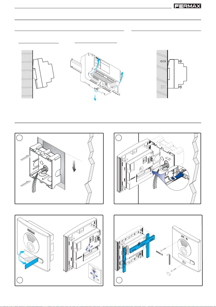
INSTALACIÓN DEL ALIMENT ADOR
Instalación en carril DIN
Montaje
Desmontaje
M
A
D
E
I
N
S
50
-60
H
z. 50
V
A
M
+18V 1.5A
12V 1A
P
A
I
N
A
F
X
.
U
E
N
T
E
A
L
IM
K
IT
E
N
T
D
A
IG
C
IO
IT
N
A
L
INST ALACIÓN PLACA DE CALLE
1 2
1.70m
5.57 feet
Fijación con tornillos
IA
R
A
M
LORCA
3 4
Pag 6
Page 7
VDS iLoft KitVDS iLoft Kit
VDS iLoft KitVDS iLoft Kit
VDS iLoft Kit
VDS iLoft Kit
VDS iLoft KitVDS iLoft Kit
VDS iLoft KitVDS iLoft Kit
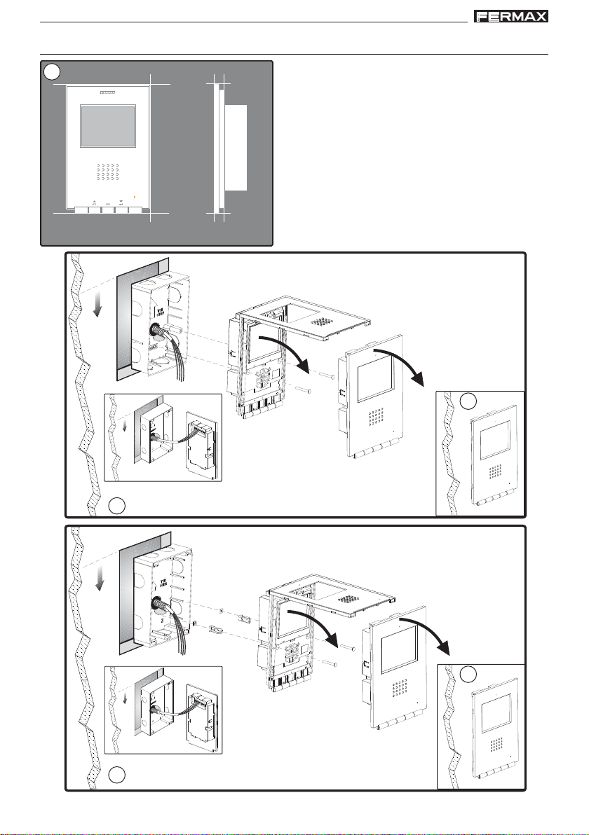
INSTALACIÓN MONIT OR
1
Dimensiones monitor (Alto x Ancho x Prof *.):
197 x 131 x 60 mm / 7,7” x 5,1” x 2,3”
Dimensiones monitor modelo Pure (Alto x Ancho x Prof *.):
197 x 131 x 59 mm / 7,7” x 5,1” x 2,3”
MENU
F1 F2
131mm
m
0
t
e
.6
1
fe
5
.2
5
1.60m
5.25 feet
2a
197mm
XXmm
14mm
F2
F1
T
A+ L-
Ct
+MV
MV
Instalación con CAJA FERMAX
Dimensiones caja Fermax (Alto x Ancho x Prof.):
158 x 108 x 45 mm / 6,2” x 4,2” x 1,7”
Dimensiones caja universal (Alto x Ancho x Prof.):
174 x 114 x 50 mm / 6.8” x 4,5” x 2”
Notas:
- este monitor se puede instalar en una caja universal.
- Prof * : la profundidad del Monitor se ha considerado con
caja Fermax
(*) Quitar la etiqueta electrostática de protección.
(*)
(*)
3
(*) Quitar la etiqueta electrostática de protección.
1.60m
5.25 feet
F
2
1
T
A
+
C
t
L-
m
0
t
6
e
.
e
1
f
5
2
.
5
Instalación con CAJA UNIVERSAL
2b
+MVMVF
(*)
(*)
3
Pag 7
Page 8
VDS iLoft KitVDS iLoft Kit
VDS iLoft KitVDS iLoft Kit
VDS iLoft Kit
VDS iLoft Kit
VDS iLoft KitVDS iLoft Kit
VDS iLoft KitVDS iLoft Kit
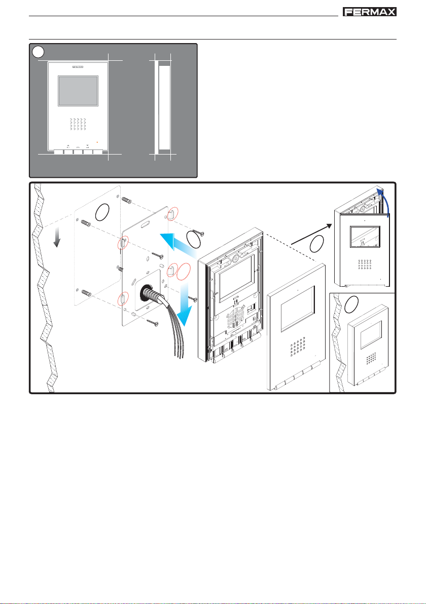
INST ALACIÓN MONITOR SUPERFICIE
1
197mm
MENU
F1 F2
Dimensiones monitor (Alto x Ancho x Prof .):
197 x 131 x 34,3 mm / 7,7” x 5,1” x 1,3”
Dimensiones monitor modelo Pure (Alto x Ancho x Prof .):
197 x 131 x 33,3 mm / 7,7” x 5,1” x 1,3”
1.60m
5.25 feet
131mm
1
34,3mm
(*) Quitar la etiqueta electrostática de protección.
2
3
4
5
Pag 8
Page 9
VDS iLoft KitVDS iLoft Kit
ON
D
C
B
A
E
VDS iLoft KitVDS iLoft Kit
VDS iLoft Kit
VDS iLoft Kit
VDS iLoft KitVDS iLoft Kit
VDS iLoft KitVDS iLoft Kit
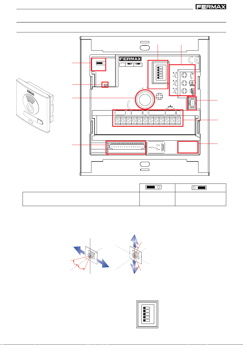
DESCRIPCIÓN DE LOS EQUIPOS
Placa de calle
A)
B)
C)
E) F)
AMPLIFICADOR - VERSTÄRKER
VDS
JP2
JP2
MASTER
DL2
DL2
18V
DC
-
+
L
V
SLAVE
PAN & TILT
M
10
+12
AMPLIFICATEUR - AMPLIFIER
ON
A
B
C
D
E
IDIOMA
LANGUAGE
EXIT
NCNO
BS
C
-
AUDIO
S
MIC
G )
H )
D)
Puentes de configuración:
A)
JP2 : Selección Placa Principal / Placa Secundaria.
Configuración por defecto: Placa Principal
B) DL2: Led de diagnóstico.
Si existe un cortocircuito entre + y L, al llamar desde placa emite una serie de destellos cortos.
C) Enfoque de telecámara:
10º
10º
D) CN7: Video test monitor
Conector de test y programación de monitores
E) Síntesis de voz:
Selección del idioma del mensaje de «puerta abierta».
Ver CODIFICACIÓN al final de este manual.
ALIMENTACION
POWER SUPPLY
+-
18 Vdc
CN7
MONITOR TEST
NO
C
NC
(*)
Placa Principal Placa Secundaria
10º
Pan&Tilt (±10º)
10º
I)
Pag 9
Page 10

VDS iLoft KitVDS iLoft Kit
VDS iLoft KitVDS iLoft Kit
VDS iLoft Kit
VDS iLoft Kit
VDS iLoft KitVDS iLoft Kit
VDS iLoft KitVDS iLoft Kit
F) Ajustes de Audio:
G) MIC
Conexión micrófono (micrófono ubicado en el perfil inferior de la placa).
“puerta abierta”
H) Conectores Placa:
• Bornas de video, (coaxial).
V: vivo
M: malla
Ct: activación telecamara (11 Vdc)
• Bornas de Conexión del sistema:
+, -: alimentación (18 Vdc).
L: bus de datos.
+12: salida12 Vdc
C, NO, NC: contactos relé (conexión abrepuertas)
BS, -: pulsador zaguán.
SP, - : sensor de puerta abierta.
S: activación del cambiador
I) Versión del amplificador.
Monitor iLOFT
Conexionado
• Bornas de video, (coaxial).
V: vivo
M: malla
Ct: activación telecamara (11 Vdc)
• Bornas de Conexión:
+, -: alimentación (18 Vdc).
L: bus de datos.
F1, F2: funciones adicionales. Ver capítulo programación.
T, -: Conexión pulsador de llamada puerta vivienda (P1)
A, - : Conexión prolongador de llamada ref.2040,
activador luces y timbres ref. 2438, etc...
Funciones disponibles en el Monitor
• Las funciones disponibles en el monitor iLoft VDS se resumen en la siguiente lista:
- Apertura de puerta por comando.
- Llamada a Conserje.
- Regulación de volumen de llamada.
- Desconexión de llamada (No molestar).
- Selección de melodía (7 opciones).
- Timbre de puerta.
- Programación desde el terminal y desde placa de calle.
- Regulación del volumen del audio de subida.
- Configuración de parámetros por menú en pantalla (OSD).
- Apertura automática de puerta (Doormatic).
- Lift Control.
- Ajustes de brillo, contraste y color.
••
• Para más información del monitor descargar el manual en: www.fermax.com
••
Pag 10
Page 11
VDS iLoft KitVDS iLoft Kit
VDS iLoft KitVDS iLoft Kit
VDS iLoft Kit
VDS iLoft Kit
VDS iLoft KitVDS iLoft Kit
VDS iLoft KitVDS iLoft Kit
PROGRAMACIÓN DEL MONITOR iLOFT
¡El monitor no funcionará mientras no haya sido programado!
Opción 1: Desde Placa + Monitor
1
2
PROG
P
R
.
O
G
.
2 seg.
< 2 min 30 sec.
P
R
O
G
.
1º. Con el monitor conectado pulse el botón de programación durante 2 segundos
«PROG
» (para acceder a éste es necesario levantar la tapa frontal). Se oirá un
sonido de confirmación.
2º. Pulse el botón de llamada a vivienda. De nuevo se produce confirmación con otro tono
de llamada diferente.
Nota:
El tiempo entre los pasos 1 y 2 debe ser inferior a 2 minutos y medio.
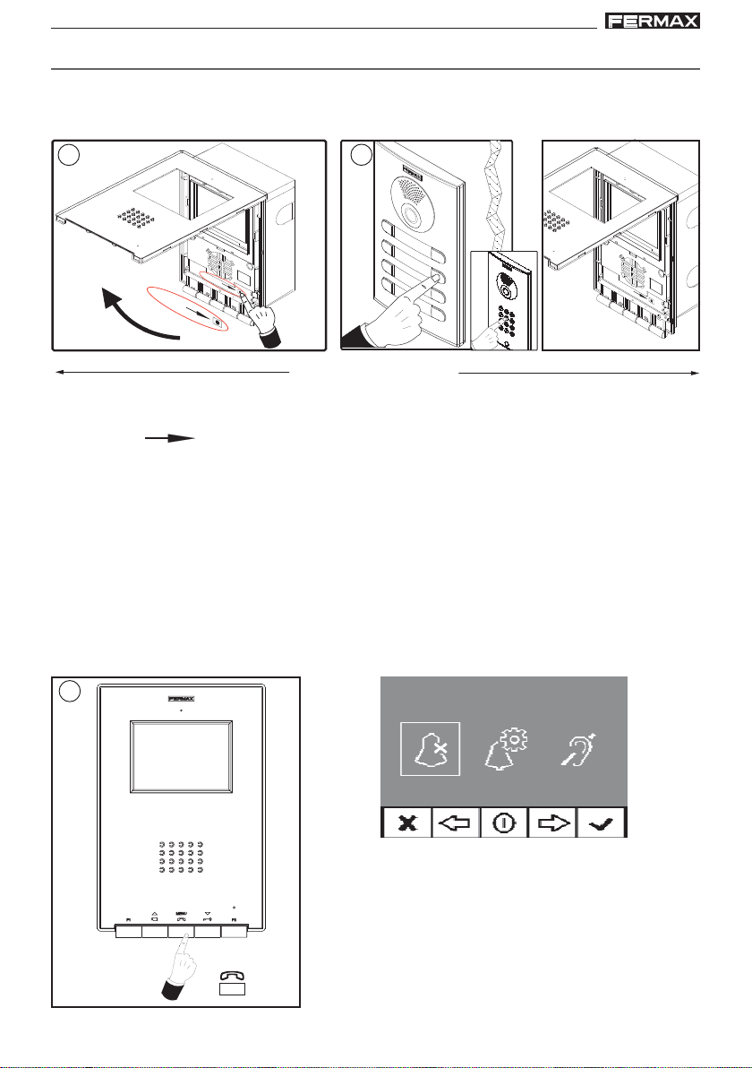
Opción 2: Desde Monitor: Es posible programar el monitor mediante el menú en pantalla.
1º. Entrar en menú Usuario. Pulsar «Menú» 1 segundo.
1
(*)
1"
¸
MENU
menú usuario
Nota: Si el monitor está sin programar , al pulsar «Menú»
1 segundo
, se accede directamente al «Menú
ADMINISTRADOR», ver página siguiente.
(*) Función disponible según modelo.
Pag 11
Page 12
VDS iLoft KitVDS iLoft Kit
VDS iLoft KitVDS iLoft Kit
VDS iLoft Kit
VDS iLoft Kit
VDS iLoft KitVDS iLoft Kit
VDS iLoft KitVDS iLoft Kit
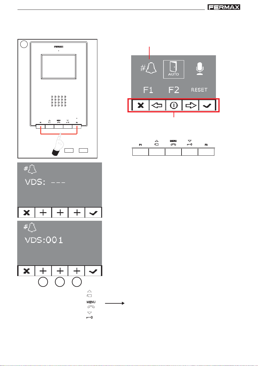
2º. Estando en menú Usuario, entrar en menú ADMINISTRADOR (Pulsando F1+F2 simultá-
neamente durante 5 segundos). Estando en el menú ADMINISTRADOR seleccionar la
primera opción.
2
5"
¸
F1 F2
seleccionar la primera opción
menú administrador
Los iconos visualizados en la pantalla se
manejan con los botones correspondientes
ubicados en el monitor
+
En ese momento, lo primero que hace el monitor es
indicar mediante la PANTALLA el número del monitor
actual. Si no está programado mostrará: - - -
Nota: Cuando el terminal no está programado se indica mediante el parpadeo muy lento del led azul.
3º. Programar el número de llamada: Cada vez que se
presiona el botón correspondiente a centenas, decenas o unidades se incrementa una cifra y se
visualiza en el DISPLA Y.
a
a) Centenas: Pulsar el botón
b) Decenas: Pulsar el botón
c) Unidades: Pulsar el botón
4º. Salir de programación: Pulsar el botón «Validar» para confirmar el número escogido.
Se sale al menú anterior de programación.
Pag 12
c
b
Una vez se llega al 9 y se vuelve a
presionar continúa con el 0. La siguiente
pulsación comienza desde el número 1.
Page 13
VDS iLoft KitVDS iLoft Kit
VDS iLoft KitVDS iLoft Kit
VDS iLoft Kit
VDS iLoft Kit
VDS iLoft KitVDS iLoft Kit
VDS iLoft KitVDS iLoft Kit
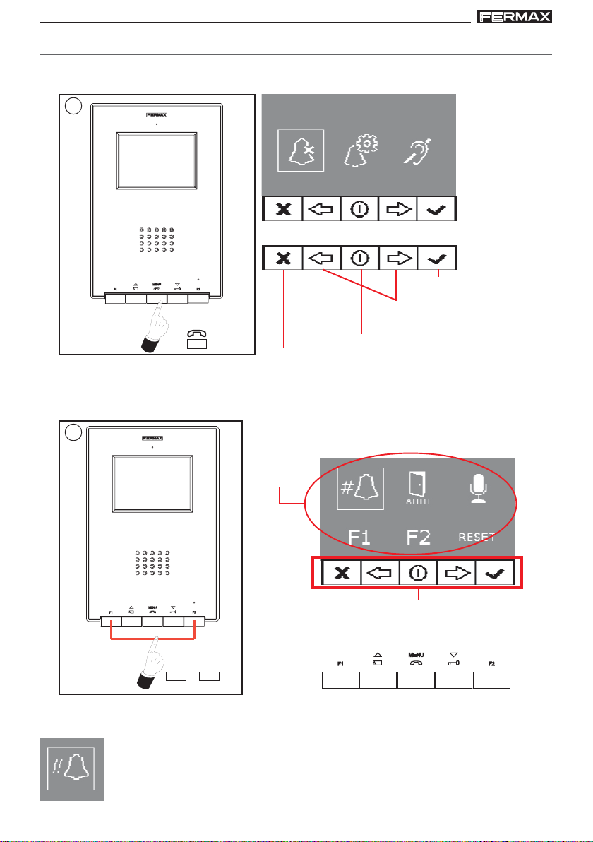
PROGRAMACIÓN: Menú ADMINISTRADOR
Acceder al menú administrador
1º. Entrar en menú Usuario. Pulsar «Menú» 1 segundo.
1
(*)
(*) Función
disponible
según
modelo.
menú usuario
Tecla de confirmación.
Teclas de desplazamiento
1"
¸
2º. Estando en menú Usuario, entrar en menú ADMINISTRADOR (Pulsando F1+F2 simultá-
neamente durante 5 segundos). Estando en el menú ADMINISTRADOR seleccionar la
primera opción.
MENU
Tecla salir menú programación.
Tecla cancelar
en los menús
2
iconos
gráficos
Los iconos visualizados en la pantalla se
manejan con los botones correspondientes
ubicados en el monitor
5"
¸
F1 F2
menú administrador
+
Desde este menú se puede acceder a las diferentes opciones y funcionalidades que
muestran los iconos gráficos.
Programación del monitor desde el propio monitor
Explicado en la página anterior.
Pag 13
Page 14
VDS iLoft KitVDS iLoft Kit
VDS iLoft KitVDS iLoft Kit
VDS iLoft Kit
VDS iLoft Kit
VDS iLoft KitVDS iLoft Kit
VDS iLoft KitVDS iLoft Kit
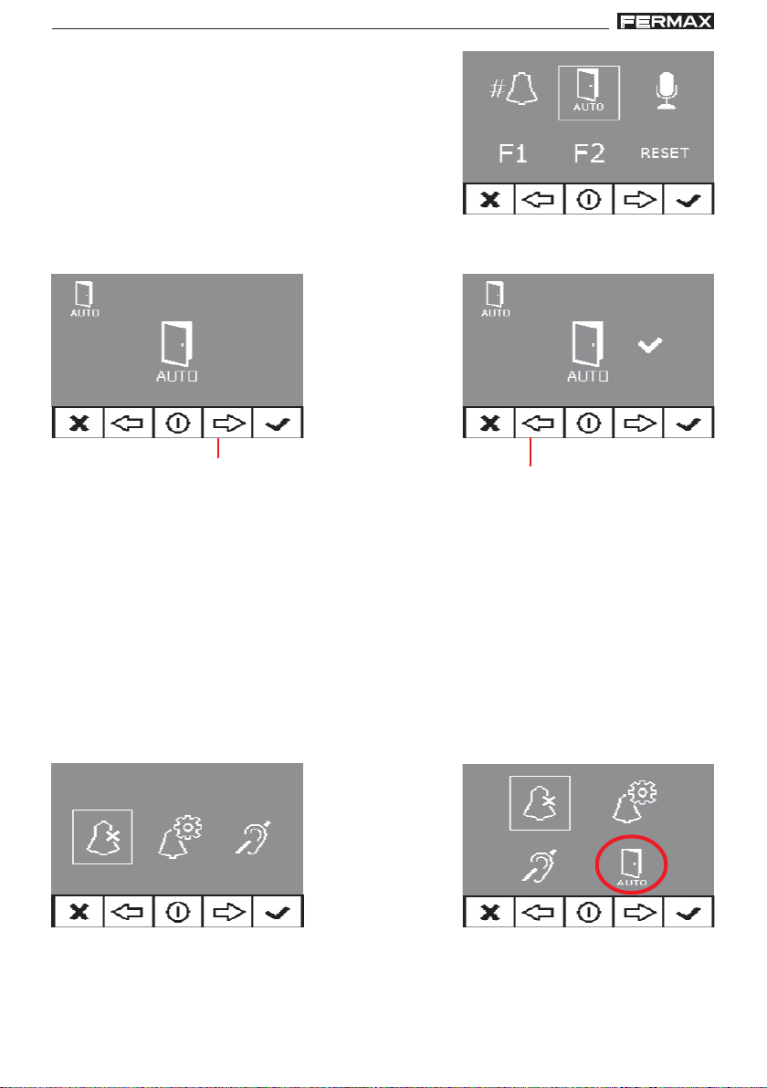
Apertura automática (Doormatic)
La función de apertura automática está por defecto
deshabilitada (no disponible al usuario) y debe ser el
instalador desde el menú administrador el que la
habilite, si se desea, accediendo a la opción
especificada.
Seleccionando esta opción, se accede al submenú que permite habilitar el modo
doormatic o deshabilitarlo.
deshabilitado habilitado
Notas:
- En función de si está habilitado o no, la opción de doormatic estará o no disponible
en el menú de usuario.
- Como opción se puede conectar un reloj temporizador diario en la entrada del timbre
de puerta (si no se utiliza éste) para que, de manera automática, active y desactive la
apertura automática cada día en el horario programado. Si esa entrada se activa
durante un tiempo superior a 30 segundos, se determina que se debe activar la
apertura automática. Cuando se desactive la entrada del timbre de puerta también
se desactivará la función.
es posible habilitar el modo
doormatic, pulsando la flecha de
la derecha
flecha izquerda para
deshabilitar el modo doormatic
(*)
(*)
menú usuario: función Doormatic
NO HABILITADA por el instalador
menú usuario: función Doormatic
HABILITADA por el instalador
(*) Función disponible según modelo.
Pag 14
Page 15
VDS iLoft KitVDS iLoft Kit
VDS iLoft KitVDS iLoft Kit
VDS iLoft Kit
VDS iLoft Kit
VDS iLoft KitVDS iLoft Kit
VDS iLoft KitVDS iLoft Kit
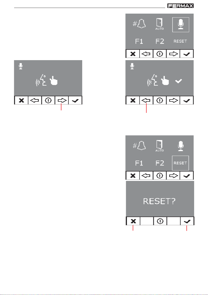
Configuración Modo de conversación
Dentro del menú de conversación se puede seleccionar entre modo Simplex y Manos Libres.
Por defecto está seleccionado el modo manos libres.
Modo Simplex: pulsar para hablar y soltar para escu-
char el botón de activación de audio, botón «MENU».
manos libres modo simplex
Reset de parámetros
Se dispone de la posibilidad de resetear los
parámetros a valores por defecto seleccionando la
opción en el menú de instalador y confirmando la
operación.
Este reset no modificará el número de terminal
programado.
Los parámetros que modificará serán:
- Melodía seleccionada para placa principal. DingDong-Dang.
- Melodía seleccionada para placa secundaria.
Bitonal Fermax.
- Melodía seleccionada para timbre de puerta. DingDong.
- Volumen de tono de llamada. Volumen medio de
llamada.
- Volumen conversación. Volumen medio de
conversación.
- Ajustes de brillo, contraste y color. Ajustes iniciales.
- Modo no molestar. Desactivado
- Funcionalidad borna F1. Pánico OFF.
- Funcionalidad borna F2. Lift Control OFF.
- Doormatic. Deshabilitado.
es posible seleccionar el modo
simplex, pulsando la flecha de
la derecha
flecha izquerda para quitar
el modo simplex
aceptarcancelar
Pag 15
Page 16
VDS iLoft KitVDS iLoft Kit
VDS iLoft KitVDS iLoft Kit
VDS iLoft Kit
VDS iLoft Kit
VDS iLoft KitVDS iLoft Kit
VDS iLoft KitVDS iLoft Kit
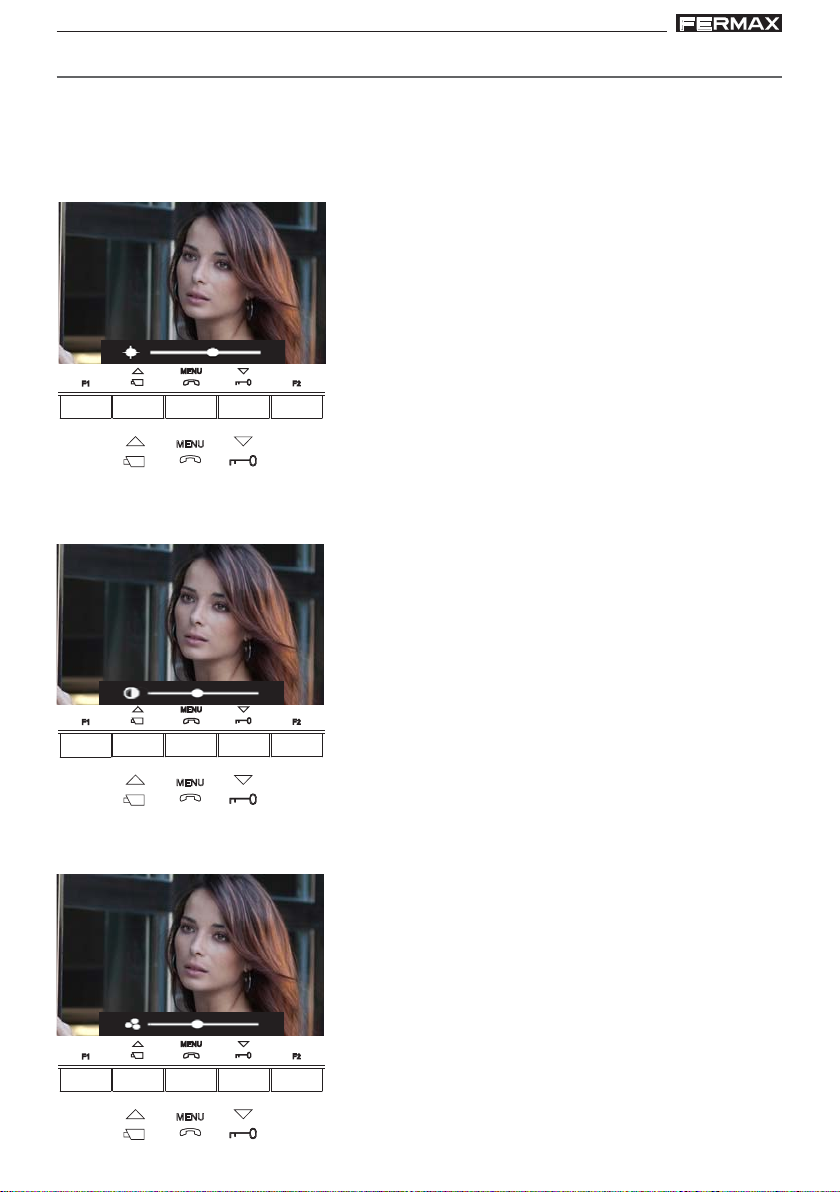
AJUSTES: Video y Audio
Ajuste Video: Brillo - Contraste - Color
El monitor permite realizar los ajustes de brillo, contraste y color mientras se halla
recibido una llamada o realizado un autoencendido y no se halla iniciado la conversación.
Para ello se pulsará durante 5 segundos el botón «MENU» y aparecerá en pantalla un
menú contextual para el ajuste del brillo de la imagen.
tecla «MENU» (5 seg.): acceder menú brillo
Estando en menú brillo:
tecla «ABREPUERTAS»: aument ar brillo
tecla «CAM»: disminuir brillo
CAM
MENU
Abrepuertas
Estando en brillo, al realizar una pulsación corta sobre MENU pasa al ajuste del nivel de
contraste.
Pulsación corta tecla «MENU»: acceder menú contraste
Estando en menú contraste:
tecla «ABREPUERTAS»: aument ar contraste
tecla «CAM»: disminuir contraste
CAM
MENU
Abrepuertas
Estando en contraste, al realizar una pulsación corta sobre MENU pasa al ajuste del
nivel de color.
Pulsación corta tecla «MENU»: acceder menú color
Estando en menú color:
tecla «ABREPUERTAS»: aument ar color
tecla «CAM»: disminuir color
Pag 16
CAM
MENU
Abrepuertas
Page 17
VDS iLoft KitVDS iLoft Kit
VDS iLoft KitVDS iLoft Kit
VDS iLoft Kit
VDS iLoft Kit
VDS iLoft KitVDS iLoft Kit
VDS iLoft KitVDS iLoft Kit
Y con la pulsación de MENU desaparece el menú contextual quedando ajustado el video
con los niveles establecidos.
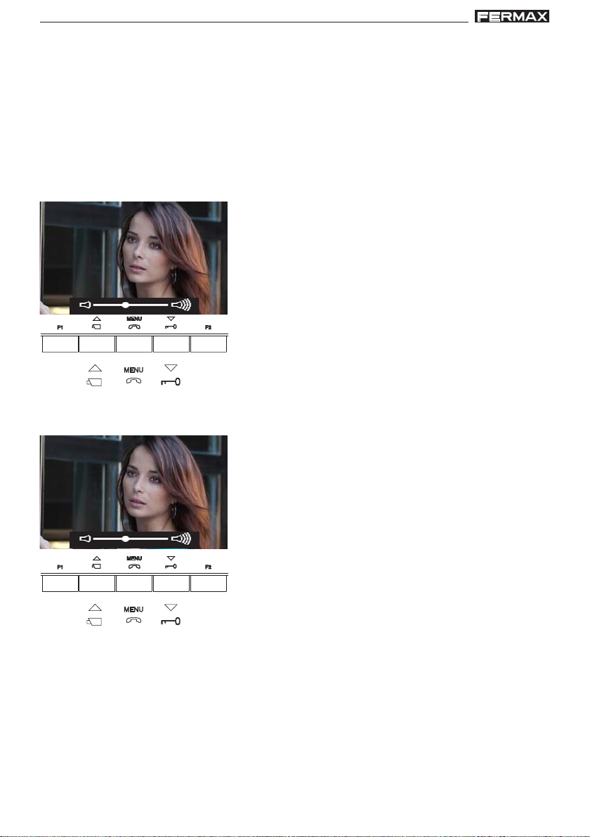
Ajuste Audio
Durante el tiempo que está abierto el canal de audio se puede regular el volumen del
audio de subida mediante un menú contextual que aparecerá en pantalla. Si estamos
en:
- Modo conversación «Manos Libres» será necesario pulsar tecla MENU durante 5s.
- Modo conversación «Simplex» hay que pulsar simultáneamente F1 + F2 durante 1
segundo.
Modo conversación «Manos Libres», estando abierto
el canal de audio:
tecla «MENU» (5 seg.): acceder menú ajuste audio
Estando en menú ajuste audio:
tecla «ABREPUERTAS»: aument ar nivel audio
tecla «CAM»: disminuir nivel audio
CAM
MENU
Abrepuertas
Modo conversación «Simplex», estando abierto el canal de audio:
Pulsar simultáneamente teclas «F1 + F2» (1 seg.): acceder menú ajuste audio
Estando en menú ajuste audio:
tecla «ABREPUERTAS»: aument ar nivel audio
tecla «CAM»: disminuir nivel audio
CAM
MENU
Abrepuertas
Nota: Mientras se esté regulando el audio, sólo estará activo el audio de subida. Al acceder al «menú ajuste de audio» se desconecta el audio de bajada y solo se escucha el
audio de subida que es el que podremos regular mientras están hablando desde la
placa de calle.
El ajuste del audio terminará por la pulsación de la tecla «MENU».
Pag 17
Page 18
VDS iLoft KitVDS iLoft Kit
VDS iLoft KitVDS iLoft Kit
VDS iLoft Kit
VDS iLoft Kit
VDS iLoft KitVDS iLoft Kit
VDS iLoft KitVDS iLoft Kit
ESQUEMA DE CABLEADO (COAX)
(*) IMPORT ANTE
Colocar una resistencia de 10 Kohms entre los
bornes + y L del último monitor.
P1: Pulsador de llamada puerta vivienda.
M
A
D
E
I
N
S
P
A
I
N
5
0
6
0
H
z
.
5
0
V
A
M
A
F
X
+
.
U
1
8
E
V
N
T
1
D. max.
30 m
E
2
1
V
A
.
5
L
A
I
K
M
1
I
E
T
A
N
T
D
A
I
C
G
I
O
I
T
N
A
L
Vac
18 Vdc
-+-
+
~
~
240V
12 Vac
OVERLOAD
ON
~~
INPUT
18Vdc+12Vac
100-240 V ; 1,2A
50-60 Hz
OUTPUT
18 V ; 1.5
12 V ;
12 Vac
10 Kohm
Ct + MVMVF1TAL-F2
75 Ohm
metros / metres
1 - 50
50 - 100
100 - 200
P1
D
pies / feet
3 - 150 17
150 - 300
300 - 600
S
mm
mm1
mm
1,5
mm2,5
2
AWG
2
2
15
2
13
75 Ohm
75 Ohm
75 Ohm
+ L
COAX
+
L
-
Pag 18
12 Vac
JP2
ALIMENTACION
POWER SUPPLY
+-
18 Vdc
AMPLIFICADOR - VERSTÄRKER
VDS
V
SLAVE
PAN & TILT
M
AMPLIFICATEUR - AMPLIFIER
A
B
C
D
E
IDIOMA
LANGUAGE
10
+12
NCNO
C
NO
C
NC
ON
AUDIO
EXIT
BS
-
MIC
S
JP2
MASTER
DL2
DL2
18V
DC
-
+
L
MONITOR TEST
CN7
Page 19
VDS iLoft KitVDS iLoft Kit
VDS iLoft KitVDS iLoft Kit
VDS iLoft Kit
VDS iLoft Kit
VDS iLoft KitVDS iLoft Kit
VDS iLoft KitVDS iLoft Kit
(*) IMPORT ANTE
Colocar una resistencia de 10 Kohms entre los
bornes + y L del último monitor.
P1: Pulsador de llamada puerta vivienda.
M
A
D
E
I
N
S
P
A
I
N
5
0
6
0
H
z
.
5
0
V
A
M
A
FU
X
+
.
1
8
E
V
NT
1
18 Vdc
12 Vac
12 Vac
E
1
2
A
V
.
5
LI
A
KIT
M
1
E
A
NT
DIGIT
A
CIO
N
AL
-+-
+
ON
OVERLOAD
~~
Vac
~
~
240V
INPUT
18Vdc+12Vac
100-240 V ; 1,2A
50-60 Hz
OUTPUT
18 V ; 1.5
12 V ;
D. max.
30 m
10 Kohm
Ct + MVMVF1TAL-F2
75 Ohm
+ L
P1
Ct + MVMVF1TAL-F2
P1
D
metros / metres
1 - 50
50 - 100
100 - 200
pies / feet
3 - 150 17
150 - 300
300 - 600
JP2
COAX
+
L
-
DL2
DL2
18V
+
S
2
AWG
mm
2
mm1
2
mm
1,5
JP2
SLAVE
MASTER
DC
-
L
V
mm2,5
AMPLIFICADOR - VERSTÄRKER
VDS
AMPLIFICATEUR - AMPLIFIER
A
B
C
D
E
PAN & TILT
10
+12
M
C
2
IDIOMA
LANGUAGE
15
13
NCNO
75 Ohm
75 Ohm
75 Ohm
ON
AUDIO
EXIT
BS
-
MIC
S
12 Vac
ALIMENTACION
POWER SUPPLY
+-
18 Vdc
CN7
MONITOR TEST
NO
C
NC
Pag 19
Page 20
VDS iLoft KitVDS iLoft Kit
VDS iLoft KitVDS iLoft Kit
VDS iLoft Kit
VDS iLoft Kit
VDS iLoft KitVDS iLoft Kit
VDS iLoft KitVDS iLoft Kit
ESQUEMA DE CABLEADO (5 HILOS / UTP CA T5)
(*) IMPORT ANTE
Colocar una resistencia de 10 Kohms entre los
bornes + y L del último monitor.
P1: Pulsador de llamada puerta vivienda.
M
A
D
E
I
N
S
P
A
I
N
5
0
6
0
H
z
.
5
0
V
A
M
A
F
X
+
.
U
1
8
E
V
N
T
1
D. max.
30 m
E
2
1
V
A
.
5
L
A
I
K
M
1
I
E
T
A
N
T
D
A
I
C
G
I
O
I
T
N
A
L
10 Kohm
+ L
Vac
18 Vdc
-+-
+
~
~
240V
12 Vac
OVERLOAD
ON
V
~~
M
+
L
metros / metres
-
INPUT
18Vdc+12Vac
100-240 V ; 1,2A
50-60 Hz
OUTPUT
18 V ; 1.5
12 V ;
12 Vac
P1
D
pies / feet
1 - 50
3 - 150 17
150 - 300
50 - 100 mm1,5
BUS 5 hilos
S
2
AWG
mm
2
mm1
2
Ct + MVMVF1TAL-F2
75 Ohm
V
M
+
-
L
15
UTP CAT5
Pag 20
12 Vac
JP2
ALIMENTACION
POWER SUPPLY
+-
18 Vdc
AMPLIFICADOR - VERSTÄRKER
VDS
V
SLAVE
PAN & TILT
M
AMPLIFICATEUR - AMPLIFIER
A
B
C
D
E
IDIOMA
LANGUAGE
10
+12
NCNO
C
NO
C
NC
ON
AUDIO
EXIT
BS
-
MIC
S
JP2
MASTER
DL2
DL2
18V
DC
-
+
L
MONITOR TEST
CN7
Page 21
VDS iLoft KitVDS iLoft Kit
VDS iLoft KitVDS iLoft Kit
VDS iLoft Kit
VDS iLoft Kit
VDS iLoft KitVDS iLoft Kit
VDS iLoft KitVDS iLoft Kit
(*) IMPORT ANTE
Colocar una resistencia de 10 Kohms entre los
bornes + y L del último monitor.
P1: Pulsador de llamada puerta vivienda.
M
A
D
E
I
N
S
P
A
I
N
5
0
6
0
H
z
.
5
0
V
A
M
A
FU
X
+
.
1
8
E
V
N
TE
1
D. max.
2
1
AL
V
.
5
A
IM
KIT DIGIT
1
E
A
NT
A
CI
ON
AL
30 m
Vac
18 Vdc
-+-
+
~
~
240V
12 Vac
OVERLOAD
ON
~~
INPUT
18Vdc+12Vac
100-240 V ; 1,2A
50-60 Hz
OUTPUT
18 V ; 1.5
12 V ;
12 Vac
Ct + MVMVF1TAL-F2
10 Kohm
+ L
P1
Ct + MVMVF1TAL-F2
75 Ohm
75 Ohm
Ct + MVMVF1TAL-F2
P1
AUDIO
S
V
M
+
-
L
MIC
BUS 5 hilos
D
metros / metres
V
pies / feet
1 - 50
3 - 150 17
150 - 300
50 - 100 mm1,5
JP2
M
+
L
S
2
AWG
mm
2
mm1
2
15
MASTER
SLAVE
PAN & TILT
VDS
JP2
DL2
DL2
AMPLIFICADOR - VERSTÄRKER
AMPLIFICATEUR - AMPLIFIER
ON
A
B
C
D
E
IDIOMA
LANGUAGE
10
UTP CAT5
-
18V
DC
+
+12
-
L
M
V
EXIT
NCNO
BS
C
-
12 Vac
ALIMENTACION
POWER SUPPLY
+-
18 Vdc
CN7
MONITOR TEST
NO
C
NC
Pag 21
Page 22

VDS iLoft KitVDS iLoft Kit
VDS iLoft KitVDS iLoft Kit
VDS iLoft Kit
VDS iLoft Kit
VDS iLoft KitVDS iLoft Kit
VDS iLoft KitVDS iLoft Kit
AMPLIACIONES
Este Kit puede ser ampliado con dos teléfonos o un monitor adicional sin necesidad de
fuentes de alimentación extra.
Esquema de cableado COAX
Conexión Monitor adicional
10 KOhm
Ct + MVMVF1TAL-F2
75 Ohm
Alimentador
18Vdc
Ct + MVMVF1TAL-F2
+
COAX
L
-
Conexión Monitor adicional
75 Ohm
Pag 22
Ct + MVMVF1TAL-F2Ct + MVMVF1TAL-F2
Alimentador
18Vdc
DISTRIBUIDOR VIDEO 2 SALIDAS
REF.2448
2 OUTPUTS VIDEO DISTRIBUTOR
+
+
-
L
(-)
2
R
V5V1M
6
+18
M
V
VM M
34
R1
75
Page 23

VDS iLoft KitVDS iLoft Kit
VDS iLoft KitVDS iLoft Kit
VDS iLoft Kit
VDS iLoft Kit
VDS iLoft KitVDS iLoft Kit
VDS iLoft KitVDS iLoft Kit
Conexión teléfonos adicionales
10 KOhm
+
A
F1F2
-
+L
SW1
T
+
-
L
F1F2
-
+L
SW1
Esquema de cableado 5 HILOS / UTP CA T5
Conexión Monitor adicional
10 KOhm
Ct + MVMVF1TAL-F2
75 Ohm
+
A
T
+
-
L
Ct + MVMVF1TAL-F2
75 Ohm
+
COAX
L
-
Alimentador
18Vdc
Ct + MVMVF1TAL-F2
Alimentador
18Vdc
M
V
+
L
-
Pag 23
Page 24

VDS iLoft KitVDS iLoft Kit
VDS iLoft KitVDS iLoft Kit
VDS iLoft Kit
VDS iLoft Kit
VDS iLoft KitVDS iLoft Kit
VDS iLoft KitVDS iLoft Kit
Conexión Monitor adicional
75 Ohm
L
DISTRIBUIDOR VIDEO 2 SALIDAS
REF.2448
R
2 OUTPUTS VIDEO DISTRIBUTOR
+
(-)
2
+18
V5V1M
M
V
34
R1
75
6
VM M
Ct + MVMVF1TAL-F2Ct + MVMVF1TAL-F2
V
M
+
-
V
M
+
-
L
Alimentador
18Vdc
Conexión teléfonos adicionales
10 KOhm
+
A
F1F2
-
+L
T
+
-
SW1
Pag 24
L
F1F2
-
+L
SW1
+
A
T
+
-
L
Ct + MVMVF1TAL-F2
75 Ohm
M
V
+
L
-
Alimentador
18Vdc
Page 25

VDS iLoft KitVDS iLoft Kit
VDS iLoft KitVDS iLoft Kit
VDS iLoft Kit
VDS iLoft Kit
VDS iLoft KitVDS iLoft Kit
VDS iLoft KitVDS iLoft Kit
CARACTERÍSTICAS TÉCNICAS
Alimentación
Consumo
en reposo
IP43
Temperatura de funcionamiento
Potencia audio sentido vivienda-calle
Potencia audio sentido calle-vivienda
Volumen regulable en ambos sentidos
Temperatura de funcionamiento
Humedad
Pantalla OSD
Resolución
Señal de video
Dimensiones empotrar
Dimensiones superficie
Alto x Ancho x Prof
video activo
audio y video activo
Alimentación
Consumo
reposo
video
audio + video
TFT 3.5”
Señal compuesta 1 Vpp 75 Ω, 7 Mhz.
18 Vdc
57 mA
180 mA
390 mA
[-10 , +60 °C]
[14, 140ºF]
1 W
0,15 W
18 Vdc
26 mA
160 mA
250 mA
[5 , +40 °C]
[41, +104 ºF]
[5,95%]
Hor.: 480 Line TV
Ver.: 234 Line TV
197 x 131 x 60 mm / 7,7” x 5,1” x 2,3”
197 x 131 x 34,3 mm / 7,7” x 5,1” x 1,3”
Tiempos de activación del abrepuertas
PROGRAMACIÓN AVANZADA: Tiempo de abrepuertas
Los tiempos de activación de abrepuerta programables son dos:
- Tiempo de apertura de puerta desde vivienda
- Tiempo de apertura de puerta desde botón de salida (conectado a bornas «BS» y «-»).
Realizar los siguientes pasos:
1.- Con la alimentación desconectada, realice un cortocircuito entre las bornas «Bs» y
«-» (negativo) del amplificador (o pulsar el botón de salida, si existe).
2.- Manteniendo el cortocircuito anterior conecte la alimentación del sistema (ya no
será necesario mantener el cortocircuito o el pulsador presionado).
Se produce una confirmación acustica de en entrada en programación.
3.- Tras la confirmación acústica se indica, mediante pitidos intercalados 0.5 segundos,
el tiempo de apertura desde vivienda programado actualmente.
Pag 25
Page 26

VDS iLoft KitVDS iLoft Kit
VDS iLoft KitVDS iLoft Kit
VDS iLoft Kit
VDS iLoft Kit
VDS iLoft KitVDS iLoft Kit
VDS iLoft KitVDS iLoft Kit
4.-Una vez finalizada la indicación acústica del tiempo actual, o antes de que finalice,
pulsar cualquier pulsador de la placa tantas veces como segundos se desee
programar (de 1 a 99 segundos).
Para programar el tiempo de apertura desde el pulsador de salida, estando en
modo programación de tiempos, (finalizada la indicación acústica o la programación
de tiempo de apertura desde vivienda), permancer 5 segundos sin realizar ninguna
acción.
5.- En este momento sonará una nueva confirmación acústica indicando el cambio al
modo de programación de tiempo de apertura de zaguán, y seguidamente mediante
los pitidos anteriormente comentados se indicará el tiempo programado.
6.- Una vez finalizada la indicación acústica del tiempo actual programado, o antes de
que finalice, pulsar cualquier pulsador de la placa tantas veces como segundos se
desee programar (de 1 a 99 segundos).
Para salir de programación, permanecer 5 segundos sin pulsar ninguna tecla. Sonará
un tono ‘MUOK’ indicando la salida de programación de tiempos.
Si se produce la entrada en programación de tiempos y no se pulsa ninguna tecla, a los
30 segundos automáticamente se saldrá de programación.
Pag 26
Page 27

VDS iLoft KitVDS iLoft Kit
VDS iLoft KitVDS iLoft Kit
VDS iLoft Kit
VDS iLoft Kit
VDS iLoft KitVDS iLoft Kit
VDS iLoft KitVDS iLoft Kit
Sección II - Manual del Usuario
¡Enhorabuena por adquirir un producto de calidad!
El monitor de videoportero iLoft, manos libres y con pantalla a todo color que le
permitirá comunicarse con la placa de calle, ver la persona que le está llamando
y abrirle la puerta de entrada si así lo desea.
Gracias a su menú en pantalla se incluyen nuevas prestaciones para la
configuración de los parámetros del monitor y el bucle inductivo.
Esperamos disfrute de sus funcionalidades.
www.fermax.com
Pag 27
Page 28

VDS iLoft KitVDS iLoft Kit
VDS iLoft KitVDS iLoft Kit
VDS iLoft Kit
VDS iLoft Kit
VDS iLoft KitVDS iLoft Kit
VDS iLoft KitVDS iLoft Kit
MONITOR iLOFT
Led
Botones
Botones
Botón Activación de Audio, Colgado y Ajustes configuración (menú).
· Al recibir una llamada, (se dispone de 30" para contestar antes de que se regrese a la
situación de reposo. Durante éste tiempo el led rojo se apagará para saber que está
pendiente la llamada de contestar), pulsar este botón para hablar con el visitante.
Se abre el canal de audio en sentido calle y vivienda, (el led azul se iluminará para
indicar que se está en conversación con la calle y todo lo que se diga será escuchado
en ésta), el funcionamiento es en modo manos libres.
· Pulsar al finalizar la comunicación,
enciende el led rojo).
Nota: Por defecto la temporización interna del monitor es de 90 segundos.
· Con el monitor en reposo pulsar este botón, durante 1 segundo, para entrar en
modo Configuración Usuario. Ver apartado «Programación: Menú Usuario».
Notas:
- La conversación es privada, ningún otro terminal puede escucharla.
- El modo «manos libres» es el modo por defecto.
- Durante el tiempo que está abierto el canal de audio se puede regular el audio
de subida. Ver capítulo correspondiente: «Ajuste Audio».
- Si el monitor está configurado con conversación en «modo simplex», (presionar
para hablar y soltar para escuchar),
intermitente, quedando activo el canal de audio de subida. A partir de este
momento cada vez que se pulse la tecla MENU se activará el canal de audio de
bajada (led azul fijo) y al soltarla se volverá a activar el canal de audio de
subida (led azul intermitente). Para terminar la conversación se realizará una
pulsación corta de la tecla MENU.
(al terminar se apaga de nuevo el led azul y se
se indicará activando el led azul de manera
Pag 28
Page 29

VDS iLoft KitVDS iLoft Kit
VDS iLoft KitVDS iLoft Kit
VDS iLoft Kit
VDS iLoft Kit
VDS iLoft KitVDS iLoft Kit
VDS iLoft KitVDS iLoft Kit
Botón de abrepuertas / llamada a conserje.
· Estando en conversación con la Placa de Calle, al pulsar este botón se activa el
abrepuertas.
· Con el monitor en reposo, al pulsar este botón se realiza una llamada al conserje (si
existe conserjería).
Nota: Si el canal está ocupado se genera una señal de error «BEEP» y no se
realiza la llamada al conserje.
Botón de Autoencendido / Selección cámara principal-secundaria.
· Con el monitor en reposo pulsar este botón durante 1 segundo para encender
manualmente el monitor. Para activar audio pulsar el botón
· Con video, mantener pulsado este botón durante 2 segundos para seleccionar
secuencialmente entre la camara principal y secundaria (si existe).
Notas:
- Si el canal está ocupado se genera una señal de error «BEEP» y no se
realiza el Autoencendido, ni la llamada al conserje.
- El autoencendido siempre se realiza con la placa principal excepto cuando
se ha recibido una llamada de la placa secundaria. Finalizada la
conversación, durante 30 segundos el autoencendido se realiza con la
placa secundaria. Pasado este tiempo se realizará con la placa principal.
.
F1 y F2: Botones para Funciones Adicionales.
(Asignadas por el instalador, ver capítulos correspondientes).
NOTA: La pantalla del monitor se enciende una vez finalizada la llamada desde placa.
Funcionamiento
Apertura de puerta
Al recibir una llamada desde la placa de calle, es posible abrir la
puerta en cualquier momento, pulsado el botón
Pag 29
Page 30

VDS iLoft KitVDS iLoft Kit
VDS iLoft KitVDS iLoft Kit
VDS iLoft Kit
VDS iLoft Kit
VDS iLoft KitVDS iLoft Kit
VDS iLoft KitVDS iLoft Kit
Atender una llamada:
Modo manos libres:
Al presionar el pulsador de llamada, en la Placa de Calle se
produce un tono de llamada tanto en la placa de calle como en
el monitor, encendiéndose la pantalla.
Pulsar el botón para hablar con el visitante Se abre el canal de audio
en sentido calle y vivienda, el funcionamiento es en modo manos libres.
La comunicación finalizará automáticamente a los 90 segundos o
en cualquier momento al pulsar el botón
El led permanecerá encendido (azul) durante el tiempo que dure la
conversación.
Si no se establece comunicación con la placa de calle, el monitor se
apaga automáticamente pasados 30 seg.
Si estuviera en modo de conversación simplex (presionar para
hablar el botón y soltar para escuchar).
Al presionar el pulsador de llamada, en la Placa de Calle se
produce un tono de llamada tanto en la placa de calle como en
el monitor, encendiéndose la pantalla. Pulsar el botón
hablar con el visitante, quedando activo el canal de audio de subida.
Se indica el modo simplex porque queda el led azul de manera
intermitente.
A partir de este momento cada vez que se pulse lel botón se
activará el canal de audio de bajada (led azul fijo) y al soltarla se
volverá a activar el canal de audio de subida (led azul intermitente), el funcionamiento es en modo simplex. La comunicación finali-
zará automáticamente a los 90 segundos o en cualquier momento
al realizar una pulsación corta en el botón . Al terminar se apa-
ga el led azul.
Si no se establece comunicación con la placa de calle, el monitor se
apaga automáticamente pasados 30 seg.
Activación Manual del Monitor (Autoencendido)
Con el monitor en reposo pulsar este botón y mantenerlo pulsado
hasta que aparezca la imagen (menos de 2 segundos).
En el caso de que en la instalación haya más de 1 cámara, para visualizar
la imagen de la segunda cámara se debe liberar el botón y volver a
pulsarlom hasta que aparezca la imagen de la cámara secundaria.
Para activar el audio y hablar con el visitante o abrir la puerta realizar los
pasos descritos anteriormente.
Si no se establece comunicación con la placa de calle, el monitor se
apaga automáticamente pasados 30 seg.
.
para
NOTA: Si existe más de un monitor iLoft en la instalación y se realiza la llamada a un
monitor, el resto de los monitores mostrarán el led en color azul avisando que el canal
está ocupado.
Pag 30
Page 31

VDS iLoft KitVDS iLoft Kit
VDS iLoft KitVDS iLoft Kit
VDS iLoft Kit
VDS iLoft Kit
VDS iLoft KitVDS iLoft Kit
VDS iLoft KitVDS iLoft Kit
PROGRAMACIÓN: Menú USUARIO
Acceder al menú usuario
1º. Para entrar en menú Usuario, pulsar «Menú» 1 segundo.
1
menú usuario
1"
¸
Selección de melodía
Dentro del menú de usuario, el monitor permite se-
leccionar una melodía independiente para la llamada
desde:
- placa de calle principal
- placa de calle secundaria
- el timbre de puerta.
MENU
Tecla salir menú programación.
Tecla cancelar
(*)
Tecla de confirmación.
Teclas de desplazamiento
en los menús
(*)
1. Placa Principal
(*) Función disponible según modelo.
En primer lugar, aparecerá el volumen de llamada
seleccionado actualmente y podrá variarse pulsando
las teclas correspondientes.
Posteriormente, en cada opción se muestra al entrar
el valor actual de melodía, de manera que si se quieren
escuchar los parámetros actuales, se puede realizar
la reproducción pulsando el botón identificado en
pantalla como PLAY.
. . . . . . . . . . . .
Pag 31
Page 32

VDS iLoft KitVDS iLoft Kit
VDS iLoft KitVDS iLoft Kit
VDS iLoft Kit
VDS iLoft Kit
VDS iLoft KitVDS iLoft Kit
VDS iLoft KitVDS iLoft Kit
2. Placa Secundaria
. . . . . . . . . . . .
3. Timbre de puerta
El monitor dispone de dos bornas (-,T) para conectar un pulsador externo de manera
que cuando se realice un corto entre ambas se generará un tono de llamada
identificativo.
Como se ha comentado anteriormente, la melodía del timbre de puerta es configurable
dentro del menú de melodías.
. . . . . . . . . . . .
No molestar (cancelar el tono de llamada)
Dentro del menú de usuario, se puede seleccionar el
modo No Molestar. Para ello se seleccionará el icono
correspondiente, y al pulsar validar se saldrá de la
pantalla.
Se indica el modo No Molestar con el parpadeo de 1
segundo del led rojo. Para desactivarlo, se volverá a
seleccionar la misma opción y el led rojo permanecerá
encendido mostrando modo Reposo.
(*) Función disponible según modelo.
Pag 32
(*)
activar/desactivar
Page 33

VDS iLoft KitVDS iLoft Kit
VDS iLoft KitVDS iLoft Kit
VDS iLoft Kit
VDS iLoft Kit
VDS iLoft KitVDS iLoft Kit
VDS iLoft KitVDS iLoft Kit
Apertura automática (Doormatic)
Con el modo de «apertura automática» activado cuando se reciba una llamada desde la
placa de calle se activará el abrepuertas.
La función de apertura automática está por defecto deshabilitada (no disponible al usario).
Debe haber sido habilitada previamente por el instalador , para poder ser activada por el
usuario.
(*)
(*)
menú usuario: función Doormatic
NO HABILITADA por el instalador
Seleccionando esta opción, se accede al submenú que permite activar el modo doormatic
o desactivarlo.
El usuario podrá activar/desactivar el doormatic
seleccionando la opción doormatic y pulsando validar.
Al pulsar validar se saldrá del menú de pantalla y se
(*)
activar/desactivar
desactive la apertura automática cada día en el horario programado. Si esa entrada se
activa durante un tiempo superior a 30 segundos, se determina que se debe activar la
apertura automática. Cuando se desactive la entrada del timbre de puerta también se
desactivará la función.
visualizará con el led verde si el modo doormatic está
activo. Si no está activo, el led rojo permanecerá
encendido mostrando modo Reposo.
Como opción se puede conectar un reloj temporizador
diario en la entrada del timbre de puerta (si no se
utiliza éste) para que, de manera automática, active y
menú usuario: función Doormatic
HABILITADA por el instalador
(*) Función disponible según modelo.
Pag 33
Page 34

VDS iLoft KitVDS iLoft Kit
VDS iLoft KitVDS iLoft Kit
VDS iLoft Kit
VDS iLoft Kit
VDS iLoft KitVDS iLoft Kit
VDS iLoft KitVDS iLoft Kit
Pag 34
Page 35

VDS iLoft KitVDS iLoft Kit
VDS iLoft KitVDS iLoft Kit
VDS iLoft Kit
VDS iLoft Kit
VDS iLoft KitVDS iLoft Kit
VDS iLoft KitVDS iLoft Kit
ENGLISH
Pag 35
Page 36

VDS iLoft KitVDS iLoft Kit
VDS iLoft KitVDS iLoft Kit
VDS iLoft Kit
VDS iLoft Kit
VDS iLoft KitVDS iLoft Kit
VDS iLoft KitVDS iLoft Kit
«Video Cityline iLOFT Set»
This technical document of an informative nature is published by FERMAX ELECTRONICA
S.A.U., which reserves the right to modify characteristics of the products referred to herein
at any time and without prior notice. These changes will be reflected in subsequent editions
of this document.
Cod. 97693EIb V02_13
Pag 2
ENGLISH
Page 37

VDS iLoft KitVDS iLoft Kit
VDS iLoft KitVDS iLoft Kit
VDS iLoft Kit
VDS iLoft Kit
VDS iLoft KitVDS iLoft Kit
VDS iLoft KitVDS iLoft Kit
TABLE OF CONTENTS
SECTION I - INSTALLATION MANUAL ....................................................................... 5
Installation
Power Supply ................................................................................................... 6
Entry Panel ....................................................................................................... 6
Monitor .............................................................................................................. 7
Equipment Descriptions and Settings
Entry Panel ....................................................................................................... 9
iLoft Monitor...................................................................................................... 10
Equipment Programming:
iLoft Monitor. VDS Programming.................................................................... 11
Wiring Diagram ..................................................................................................... 18
Extensions............................................................................................................. 22
Technical Features of the Equipment .............................................................. 25
SECTION II - USER MANUAL ..................................................................................... 27
iLoft Monitor.......................................................................................................... 28
Controls ............................................................................................................ 28
Operation .......................................................................................................... 29
Monitor Settings ............................................................................................... 31
Pag 3
Page 38

VDS iLoft KitVDS iLoft Kit
VDS iLoft KitVDS iLoft Kit
VDS iLoft Kit
VDS iLoft Kit
VDS iLoft KitVDS iLoft Kit
VDS iLoft KitVDS iLoft Kit
Pag 4
Page 39

VDS iLoft KitVDS iLoft Kit
VDS iLoft KitVDS iLoft Kit
VDS iLoft Kit
VDS iLoft Kit
VDS iLoft KitVDS iLoft Kit
VDS iLoft KitVDS iLoft Kit
Section I - Installer Manual
Pag 5
Page 40

VDS iLoft KitVDS iLoft Kit
VDS iLoft KitVDS iLoft Kit
VDS iLoft Kit
VDS iLoft Kit
VDS iLoft KitVDS iLoft Kit
VDS iLoft KitVDS iLoft Kit
POWER SUPPL Y INST ALLA TION
DIN rail Installation
Assembly
Disassembly
M
A
D
E
I
N
S
50
-60
H
z. 50
V
A
M
+18V 1.5A
12V 1A
P
A
I
N
A
F
X
.
U
E
N
T
E
A
L
IM
K
IT
E
N
T
D
A
IG
C
IO
IT
N
A
L
OUTDOOR PANEL INSTALLA TION
1 2
1.70m
5.57 feet
Fixing with screws
IA
R
A
M
LORCA
3 4
Pag 6
Page 41

VDS iLoft KitVDS iLoft Kit
VDS iLoft KitVDS iLoft Kit
VDS iLoft Kit
VDS iLoft Kit
VDS iLoft KitVDS iLoft Kit
VDS iLoft KitVDS iLoft Kit
INSTALLING THE MONIT OR
1
197mm
MENU
F1 F2
131mm
m
0
t
e
.6
1
fe
5
.2
5
1.60m
5.25 feet
F2
F1
T
A+ L-
Ct
14mm
+MV
MV
XXmm
Monitor Dimensions (Height x Width x Depth*):
197 x 131 x 60 mm / 7.7” x 5.1” x 2.3”
Pure model Monitor Dimensions (Height x Width x Depth*):
197 x 131 x 59 mm / 7.7” x 5.1” x 2.3”
Fermax Box Dimensions (Height x Width x Depth):
158 x 108 x 45 mm / 6.2” x 4.2” x 1.7”
Universal Box Dimensions (Height x Width x Depth):
174 x 114 x 50 mm / 6.8” x 4.5” x 2”
Note:
- this monitor can be installed in a universal box.
- Depth *: the Monitor depth stated here takes into account
the Fermax box
(*) Remove the electrostatic protective tag
(*)
(*)
3
1.60m
5.25 feet
2a
Installation with a FERMAX BOX
F
2
1
T
A
+
C
t
L-
m
0
t
6
e
.
e
1
f
5
2
.
5
2b
Installation with a UNIVERSAL BOX
+MVMVF
(*) Remove the electrostatic protective tag
(*)
(*)
3
Pag 7
Page 42

VDS iLoft KitVDS iLoft Kit
VDS iLoft KitVDS iLoft Kit
VDS iLoft Kit
VDS iLoft Kit
VDS iLoft KitVDS iLoft Kit
VDS iLoft KitVDS iLoft Kit
MONITOR INST ALLATION SURF ACE
1
197mm
MENU
F1 F2
Monitor Dimensions (Height x Width x Depth):
197 x 131 x 34.3 mm / 7.7” x 5.1” x 1.3”
Pure model Monitor Dimensions (Height x Width x Depth):
197 x 131 x 33.3 mm / 7.7” x 5.1” x 1.3”
1.60m
5.25 feet
131mm
1
34,3mm
(*) Remove the electrostatic protective tag
2
3
4
5
Pag 8
Page 43

VDS iLoft KitVDS iLoft Kit
ON
D
C
B
A
E
VDS iLoft KitVDS iLoft Kit
VDS iLoft Kit
VDS iLoft Kit
VDS iLoft KitVDS iLoft Kit
VDS iLoft KitVDS iLoft Kit
EQUIPMENT DESCRIPTION
Outdoor panel
A)
B)
C)
E) F)
AMPLIFICADOR - VERSTÄRKER
VDS
JP2
JP2
MASTER
DL2
DL2
18V
DC
-
+
L
V
SLAVE
PAN & TILT
M
10
+12
AMPLIFICATEUR - AMPLIFIER
ON
A
B
C
D
E
IDIOMA
LANGUAGE
EXIT
NCNO
BS
C
-
AUDIO
S
MIC
G )
H )
D)
A) Configuration Switches:
JP2 : Main Panel/Secondary Panel Selection.
Default Configuration: Main Panel
B) DL2: Diagnostic LED.
If there is a short circuit between + and L, calling from the panel emits a series of short flashes.
C) Video camera focus:
D) CN7: Video test monitor
Monitor Programming and T est Connector
E) Voice synthesiser:
'Door open' warning language selection.
See CODING at the end of this manual.
10º
10º
ALIMENTACION
POWER SUPPLY
+-
18 Vdc
CN7
MONITOR TEST
NO
C
NC
(*)
Main Panel Secondary Panel
10º
Pan&Tilt (
Pan&Tilt (±10º)
10º
±
10º)
I)
Pag 9
Page 44

VDS iLoft KitVDS iLoft Kit
VDS iLoft KitVDS iLoft Kit
VDS iLoft Kit
VDS iLoft Kit
VDS iLoft KitVDS iLoft Kit
VDS iLoft KitVDS iLoft Kit
F) Audio Settings:
“Door open”
G) MIC
Microphone connection (microphone is located in the interior panel profile).
H) Panel Connectors:
• Video Terminals (coaxial).
V: live
M: shield
Ct: Camera Activation (11 Vdc)
• System connection terminals:
+, -: power supply (18 Vdc).
L: data bus.
+12: 12 Vdc output
C, NO, NC: relay contacts (door-opener connection)
BS, -: entrance hall button.
SP, - : door-open sensor.
S: activation of the exchanger
I) Amplifier Version.
iLOFT Monitor
Connection
• Video terminals (coaxial)
V: live
M: mesh
Ct: Camera Activation (11 Vdc)
• Connection terminals:
+, -: 18 Vdc power supply
L: data bus
F1, F2: additional functions. See the chapter on programming
T, - : call button connection for residential Door (P1)
A,: call extension connection ref. 2040, light and bell
activator ref. 2438, etc...
Available functions
• The available functions on the iLoft VDS monitor are summarised in the list below:
- Command-based opening of door
- Call to guard
- Call volume regulation
- Call disconnection (Do not disturb)
- Ringtone selection (7 options)
- Doorbell
- Programming via the terminal and via the entry panel
- Input audio volume adjustment
- Configuration of parameters for the screen menu (OSD)
- Automatic door opening (DOORMATIC)
- Lift control
- Image adjustments (brightness, contrast and colour)
••
• For additional information of monitor , download the manual from: www.fermax.com
••
Pag 10
Page 45

VDS iLoft KitVDS iLoft Kit
VDS iLoft KitVDS iLoft Kit
VDS iLoft Kit
VDS iLoft Kit
VDS iLoft KitVDS iLoft Kit
VDS iLoft KitVDS iLoft Kit
PROGRAMMING THE iLOFT MONITOR
The monitor will not function until it has been programmed.
Option 1: From Panel + Monitor
1
2
PROG
P
R
.
O
G
.
2 seg.
< 2 min 30 sec.
P
R
O
G
.
1º. With the monitor connected, press the programming button «PROG » for 2
seconds (to access this, you must lift up the front cover). A confirmation tone will sound.
2º. Press the call-to-residence button. Again a confirmation is made with a different call
tone.
Note:
The time between steps 1 and 2 must be less than 2 and half minutes.
Option 2: From the Monitor Y ou can program the monitor via the on-screen menu.
1º. Enter in the User menu. Press «Menu» 1 second.
1
(*)
1"
¸
MENU
User Menu
Note: If the monitor is not yet programmed, press
«Menu» for 1 second
, and directly access the
«ADMINISTRATOR Menu», see the next page.
(*) Function available depending on model.
Pag 11
Page 46

VDS iLoft KitVDS iLoft Kit
VDS iLoft KitVDS iLoft Kit
VDS iLoft Kit
VDS iLoft Kit
VDS iLoft KitVDS iLoft Kit
VDS iLoft KitVDS iLoft Kit
2. When in the User menu, enter in ADMINISTRATOR menu (pressing F1 + F2 simultaneously
for 5 seconds). Once in the ADMINISTRATOR menu, select the first option.
2
5"
¸
F1 F2
Select the first option:
Administrator Menu
The icons viewed on-screen are controlled
via the corresponding buttons on the monitor.
+
The first thing the monitor then does is indicate the
number of the current monitor on the SCREEN. If it is
not programmed, it will show the following: - - -
Note: When the terminal has not been programmed
the blue led will flash very slowly.
3º. Programme the call number: Each time the button
corresponding to hundreds, tens or single units is
pressed, the figure goes up that figure and is shown
on the DISPLAY.
a
a) Hundreds: Press the button
b) Tens: Press the button
c) Single unit: Press the button
4º. Exit Programming: Press the «OK» to confirm the selected number. You return to the
previous programming menu.
Pag 12
c
b
Once you reach 9, if you press it again,
it returns to 0. The next time you press, it
will start at 1.
Page 47

VDS iLoft KitVDS iLoft Kit
VDS iLoft KitVDS iLoft Kit
VDS iLoft Kit
VDS iLoft Kit
VDS iLoft KitVDS iLoft Kit
VDS iLoft KitVDS iLoft Kit
PROGRAMACIÓN: Menú ADMINISTRADOR
Acceder al menú administrador
1º. Entrar en menú Usuario. Pulsar «Menú» 1 segundo.
1
(*)
(*) Function
available
depending on
model.
menú usuario
Tecla de confirmación.
Teclas de desplazamiento
1"
¸
2º. Estando en menú Usuario, entrar en menú ADMINISTRADOR (Pulsando F1+F2 simultá-
neamente durante 5 segundos). Estando en el menú ADMINISTRADOR seleccionar la
primera opción.
MENU
Tecla salir menú programación.
Tecla cancelar
en los menús
2
iconos
gráficos
Los iconos visualizados en la pantalla se
manejan con los botones correspondientes
ubicados en el monitor
5"
¸
F1 F2
menú administrador
+
Desde este menú se puede acceder a las diferentes opciones y funcionalidades que
muestran los iconos gráficos.
Programación del monitor desde el propio monitor
Explicado en la página anterior.
Pag 13
Page 48

VDS iLoft KitVDS iLoft Kit
VDS iLoft KitVDS iLoft Kit
VDS iLoft Kit
VDS iLoft Kit
VDS iLoft KitVDS iLoft Kit
VDS iLoft KitVDS iLoft Kit
Automatic Opening (Doormatic)
The automatic open function is disabled by default (not
availble to the user) and the installer must enable it, if
desired, from the administrator menu, accessing the
specified option.
By selecting this option you can access the submenu that allows you to enable or disable
the doormatic mode.
Deactivated Activated
Notes:
- If activated or not, the doormatic option is available or not available in the user menu.
- There is also an option to connect a timer to the doorbell (if this is not being used) so
that the automatic opening function is activated and deactivated each day at certain
times. If that entrance is activated for a period of greater than 30 seconds it determines
that the automatic door function should be activated. When this doorbell feature is
deactivated this function will also be deactivated.
you can enable the doormatic
mode by pressing the right arrow
the left arrow disables the
doormatic mode
(*)
(*)
User Menu: Doormatic function
DISABLED by the installer
User Menu: Doormatic function
ENABLED by the installer
(*) Function available depending on model.
Pag 14
Page 49

VDS iLoft KitVDS iLoft Kit
VDS iLoft KitVDS iLoft Kit
VDS iLoft Kit
VDS iLoft Kit
VDS iLoft KitVDS iLoft Kit
VDS iLoft KitVDS iLoft Kit
Conversation Mode Configuration
Within the conversation menu, you can select the
Simplex and Hands free mode.
The hands free mode is selected as default.
Simplex Mode: press the audio activation button to talk,
«MENU» button, and release to listen.
Hands free Simplex mode
Resetting the Parameters
You have the option to reset the parameters to default
values by selecting the option on the installation menu
and confirming the operation.
This reset does not change the programmed terminal´s
number.
The parameters changed are:
- Selected melody for the main panel. Ding-DongDang.
- Selected melody for the secondary panel. Bitonal
Fermax.
- Selected melody for the doorbell. Ding-Dong.
- Call tone volume medium. Call volume
- Conversation volume. Medium conversation volume
- Image adjustments (brightness, contrast and
colour). Start-up adjustments.
- Do not disturb deactivated
- F1 connection operations. Panic OFF.
- F2 connection operations. Lift Control OFF.
- Doormatic. Disabled.
you can select the simplex mode
by pressing the right arrow
the left arrow disables the
simplex mode
AcceptCancel
Pag 15
Page 50

VDS iLoft KitVDS iLoft Kit
VDS iLoft KitVDS iLoft Kit
VDS iLoft Kit
VDS iLoft Kit
VDS iLoft KitVDS iLoft Kit
VDS iLoft KitVDS iLoft Kit
ADJUSTMENTS: Audio + Video
Video adjustments: Brightness - Contrast - Colour
The monitor allows for the adjustments of brightness, contrast and colour while having
received a call or when an auto-start and no conversation has begun. For this, press the
«MENU» button for 5 seconds and a menu appears to adjust the image´s brightness.
«MENU» key(5 sec.): access the brightness menu
When in the brightness menu:
«LOCK-RELEASE» key: increase brightness
«CAM» key: decrease brightness
CAM
MENU Lock-Releases
When in brightness, a single click on the MENU takes it to the contrast level adjustment.
Short Press on the «MENU» key: access the
contrast menu
When in the contrast menu:
«LOCK-RELEASE» key: increase contrast
«CAM» key: decrease contrast
CAM
MENU
Lock-Releases
When in contrast, a single click on the MENU takes it to the colour level adjustment.
Short Press on the «MENU» key: access the colour menu
When in the colour menu:
«LOCK-RELEASE» key: increase colour
«CAM» key: decrease contrast
Pag 16
CAM
MENU
Lock-Releases
Page 51

VDS iLoft KitVDS iLoft Kit
VDS iLoft KitVDS iLoft Kit
VDS iLoft Kit
VDS iLoft Kit
VDS iLoft KitVDS iLoft Kit
VDS iLoft KitVDS iLoft Kit
And by pressing the MENU, the menu disappears, leaving the video with the established
values.
Audio Adjustments
While the audio channel is open the input audio volume can be adjusted with an onscreen menu. If we are in:
- Conversation mode «Hands free» you must press the MENU key for 5 s.
- Conversation mode «Simplex» simultaneously press the F1 + F2 buttons for 1 s.
Conversation mode «Hands free», with the audio
channel open:
«MENU» key(5 sec.): access audio settings menu
When in the audio settings menu:
«LOCK-RELEASE» key: increase volume
«CAM» key: decrease volume
CAM
MENU
Lock-Releases
Conversation mode «Simplex», with the audio channel
open:
Simultaneously press the «F1 + F2» keys (1 sec.):
access audio settings menu
When in the audio settings menu:
«LOCK-RELEASE» key: increase volume
«CAM» key: decrease volume
CAM
MENU
Lock-Releases
Note: While setting the audio, only the audio input is activated. Upon accessing the «audio
settings menu» the output audio is disconneced and you can only listen to the input audio,
which is what we regulate while talking from the Entry Panel.
The audio settings is completed by pressing the «MENU» key.
Pag 17
Page 52

VDS iLoft KitVDS iLoft Kit
VDS iLoft KitVDS iLoft Kit
VDS iLoft Kit
VDS iLoft Kit
VDS iLoft KitVDS iLoft Kit
VDS iLoft KitVDS iLoft Kit
WIRING DIAGRAM (COAX)
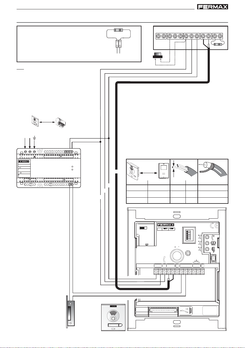
(*) IMPORTANT
Set up a 10Kohms resistance between the + and
L terminals on the last monitor.
P1: Call pushbutton at the apartment’s door.
M
A
D
E
I
N
S
P
A
I
N
5
0
6
0
H
z
.
5
0
V
A
M
A
F
X
+
.
U
1
8
E
V
N
T
1
D. max.
30 m
E
2
1
V
A
.
5
L
A
I
K
M
1
I
E
T
A
N
T
D
A
I
C
G
I
O
I
T
N
A
L
Vac
18 Vdc
-+-
+
~
~
240V
12 Vac
OVERLOAD
ON
~~
INPUT
18Vdc+12Vac
100-240 V ; 1,2A
50-60 Hz
OUTPUT
18 V ; 1.5
12 V ;
12 Vac
10 Kohm
Ct + MVMVF1TAL-F2
75 Ohm
metros / metres
1 - 50
50 - 100
100 - 200
P1
D
pies / feet
3 - 150 17
150 - 300
300 - 600
S
mm
mm1
mm
1,5
mm2,5
2
AWG
2
2
15
2
13
75 Ohm
75 Ohm
75 Ohm
+ L
COAX
+
L
-
Pag 18
12 Vac
JP2
ALIMENTACION
POWER SUPPLY
+-
18 Vdc
AMPLIFICADOR - VERSTÄRKER
VDS
V
SLAVE
PAN & TILT
M
AMPLIFICATEUR - AMPLIFIER
A
B
C
D
E
IDIOMA
LANGUAGE
10
+12
NCNO
C
NO
C
NC
ON
AUDIO
EXIT
BS
-
MIC
S
JP2
MASTER
DL2
DL2
18V
DC
-
+
L
MONITOR TEST
CN7
Page 53

VDS iLoft KitVDS iLoft Kit
VDS iLoft KitVDS iLoft Kit
VDS iLoft Kit
VDS iLoft Kit
VDS iLoft KitVDS iLoft Kit
VDS iLoft KitVDS iLoft Kit
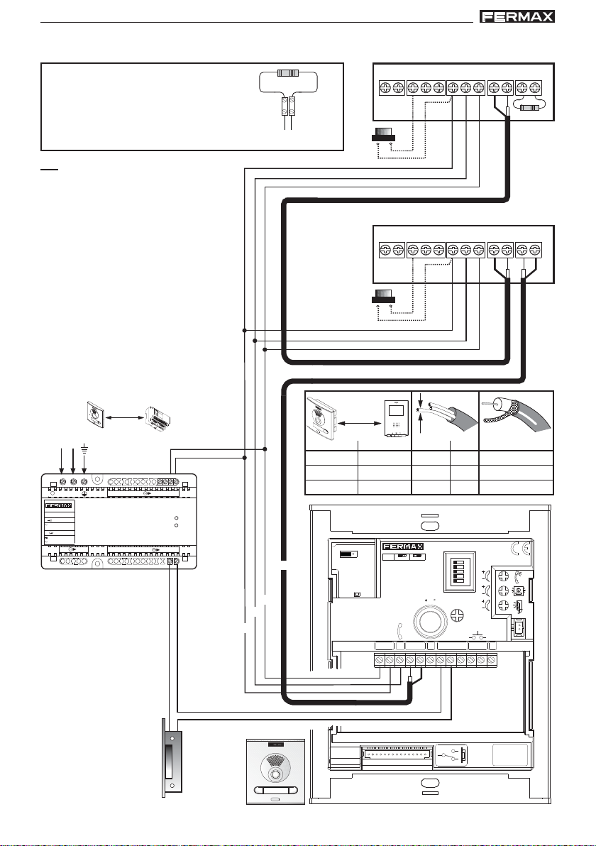
WIRING DIAGRAM (COAX)
(*) IMPORTANT
Set up a 10Kohms resistance between the + and
L terminals on the last monitor.
P1: Call pushbutton at the apartment’s door.
M
A
D
E
I
N
S
P
A
I
N
5
0
6
0
H
z
.
5
0
V
A
M
A
F
X
+
.
U
1
8
E
V
N
T
1
18 Vdc
12 Vac
12 Vac
E
2
1
V
A
.
5
L
A
I
K
M
1
I
E
T
A
N
T
D
A
I
C
G
I
O
I
T
N
A
L
-+-
+
ON
OVERLOAD
~~
Vac
~
~
240V
INPUT
18Vdc+12Vac
100-240 V ; 1,2A
50-60 Hz
OUTPUT
18 V ; 1.5
12 V ;
D. max.
30 m
10 Kohm
Ct + MVMVF1TAL-F2
75 Ohm
+ L
P1
Ct + MVMVF1TAL-F2
P1
D
metros / metres
1 - 50
50 - 100
100 - 200
pies / feet
3 - 150 17
150 - 300
300 - 600
JP2
COAX
+
L
-
DL2
DL2
18V
+
S
2
AWG
mm
2
mm1
2
mm
1,5
JP2
SLAVE
MASTER
DC
-
L
V
mm2,5
AMPLIFICADOR - VERSTÄRKER
VDS
AMPLIFICATEUR - AMPLIFIER
A
B
C
D
E
PAN & TILT
10
+12
M
C
2
IDIOMA
LANGUAGE
15
13
NCNO
75 Ohm
75 Ohm
75 Ohm
ON
AUDIO
EXIT
BS
-
MIC
S
12 Vac
ALIMENTACION
POWER SUPPLY
+-
18 Vdc
CN7
MONITOR TEST
NO
C
NC
Pag 19
Page 54

VDS iLoft KitVDS iLoft Kit
VDS iLoft KitVDS iLoft Kit
VDS iLoft Kit
VDS iLoft Kit
VDS iLoft KitVDS iLoft Kit
VDS iLoft KitVDS iLoft Kit
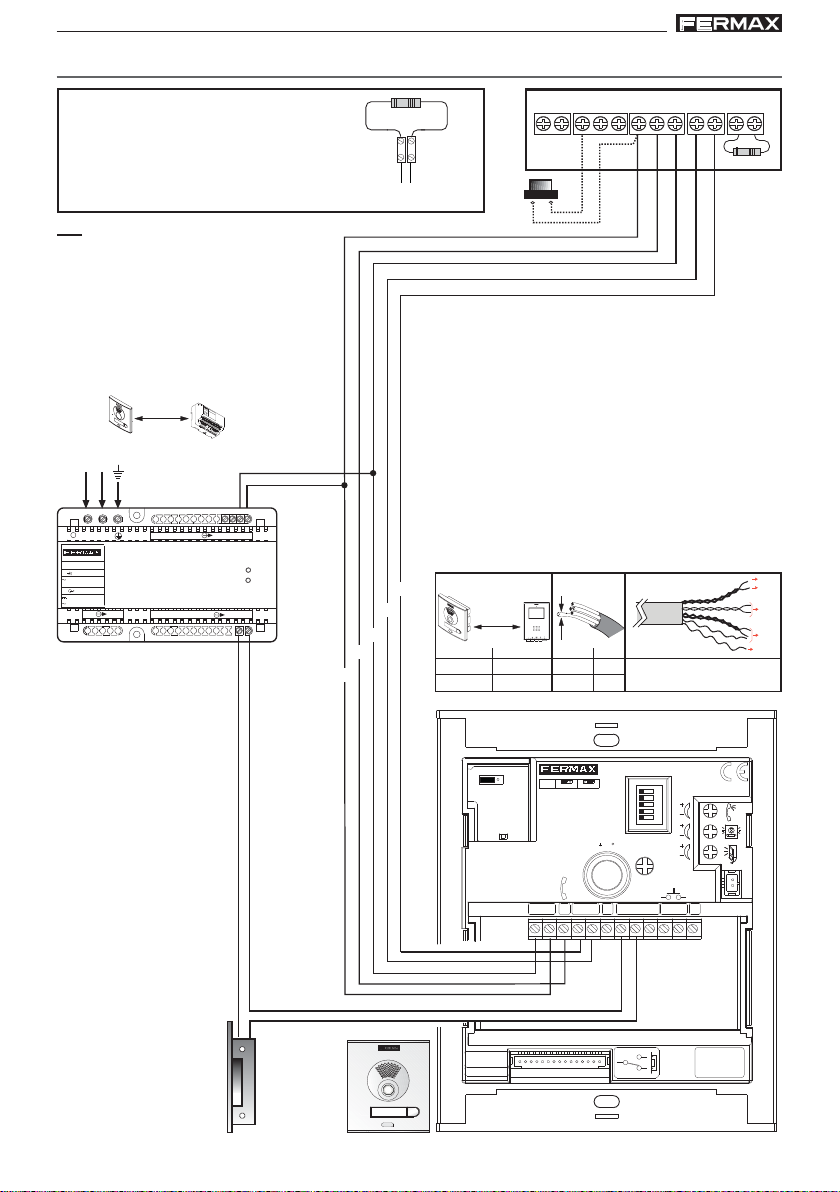
WIRING DIAGRAM (5 WIRES / UTP CA T5)
(*) IMPORTANT
Set up a 10Kohms resistance between the + and
L terminals on the last monitor.
P1: Call pushbutton at the apartment’s door.
M
A
D
E
I
N
S
P
A
I
N
5
0
6
0
H
z
.
5
0
V
A
M
A
F
X
+
.
U
1
8
E
V
N
T
1
D. max.
30 m
E
2
1
V
A
.
5
L
A
I
K
M
1
I
E
T
A
N
T
D
A
I
C
G
I
O
I
T
N
A
L
Vac
18 Vdc
-+-
+
~
~
240V
12 Vac
OVERLOAD
ON
~~
+
L
-
INPUT
18Vdc+12Vac
100-240 V ; 1,2A
50-60 Hz
OUTPUT
18 V ; 1.5
12 V ;
12 Vac
M
10 Kohm
+ L
V
P1
D
metros / metres
pies / feet
1 - 50
3 - 150 17
50 - 100 mm1,5
150 - 300
BUS 5 hilos
S
2
AWG
mm
2
mm1
2
Ct + MVMVF1TAL-F2
75 Ohm
V
M
+
-
L
15
UTP CAT5
Pag 20
12 Vac
JP2
ALIMENTACION
POWER SUPPLY
+-
18 Vdc
AMPLIFICADOR - VERSTÄRKER
VDS
V
SLAVE
PAN & TILT
M
AMPLIFICATEUR - AMPLIFIER
A
B
C
D
E
IDIOMA
LANGUAGE
10
+12
NCNO
C
NO
C
NC
ON
AUDIO
EXIT
BS
-
MIC
S
JP2
MASTER
DL2
DL2
18V
DC
-
+
L
MONITOR TEST
CN7
Page 55

VDS iLoft KitVDS iLoft Kit
VDS iLoft KitVDS iLoft Kit
VDS iLoft Kit
VDS iLoft Kit
VDS iLoft KitVDS iLoft Kit
VDS iLoft KitVDS iLoft Kit
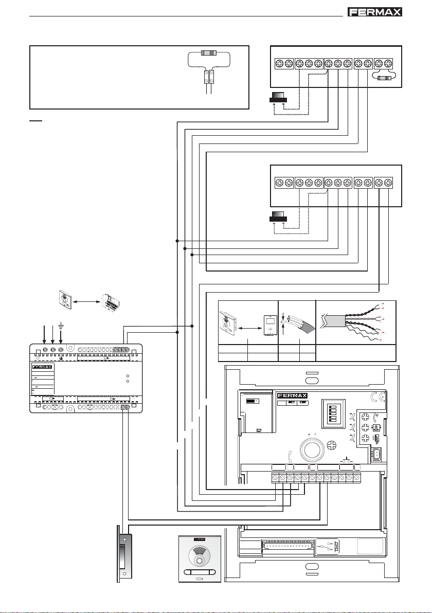
WIRING DIAGRAM (5 WIRES / UTP CA T5)
(*) IMPORTANT
Set up a 10Kohms resistance between the + and
L terminals on the last monitor.
P1: Call pushbutton at the apartment’s door.
M
A
D
E
I
N
S
P
A
I
N
5
0
6
0
H
z
.
5
0
V
A
M
A
F
X
+
.
U
1
8
E
V
N
T
1
D. max.
30 m
E
2
1
V
A
.
5
L
A
I
K
M
1
I
E
T
A
N
T
D
A
I
C
G
I
O
I
T
N
A
L
Vac
18 Vdc
-+-
+
~
~
240V
12 Vac
OVERLOAD
ON
~~
+
L
-
INPUT
18Vdc+12Vac
100-240 V ; 1,2A
50-60 Hz
OUTPUT
18 V ; 1.5
12 V ;
12 Vac
10 Kohm
+ L
metros / metres
V
M
P1
P1
D
pies / feet
1 - 50
3 - 150 17
50 - 100 mm1,5
150 - 300
JP2
DL2
DL2
+
BUS 5 hilos
S
mm
mm1
JP2
MASTER
18V
DC
-
L
2
AWG
2
2
SLAVE
PAN & TILT
M
V
Ct + MVMVF1TAL-F2
Ct + MVMVF1TAL-F2
Ct + MVMVF1TAL-F2
15
AMPLIFICADOR - VERSTÄRKER
VDS
AMPLIFICATEUR - AMPLIFIER
A
B
C
D
E
IDIOMA
LANGUAGE
10
+12
C
UTP CAT5
ON
NCNO
BS
75 Ohm
75 Ohm
V
M
+
-
L
AUDIO
EXIT
-
MIC
S
12 Vac
ALIMENTACION
POWER SUPPLY
+-
18 Vdc
CN7
MONITOR TEST
NO
C
NC
Pag 21
Page 56

VDS iLoft KitVDS iLoft Kit
VDS iLoft KitVDS iLoft Kit
VDS iLoft Kit
VDS iLoft Kit
VDS iLoft KitVDS iLoft Kit
VDS iLoft KitVDS iLoft Kit
EXTENSIONS
This Kit can be extended with two telephones or an additional monitor without the need for
extra power supplies.
Wiring diagram COAX
Additional Monitor Connection
10 KOhm
Ct + MVMVF1TAL-F2
75 Ohm
Power Supply
18Vdc
Ct + MVMVF1TAL-F2
+
COAX
L
-
Additional Monitor Connection
75 Ohm
Pag 22
Ct + MVMVF1TAL-F2Ct + MVMVF1TAL-F2
Power Supply
18Vdc
DISTRIBUIDOR VIDEO 2 SALIDAS
REF.2448
2 OUTPUTS VIDEO DISTRIBUTOR
+
+
-
L
(-)
2
R
V5V1M
6
+18
M
V
VM M
34
R1
75
Page 57

VDS iLoft KitVDS iLoft Kit
VDS iLoft KitVDS iLoft Kit
VDS iLoft Kit
VDS iLoft Kit
VDS iLoft KitVDS iLoft Kit
VDS iLoft KitVDS iLoft Kit
Additional Telephone Connection
10 KOhm
+
A
F1F2
-
+L
T
+
-
SW1
L
Wiring diagram 5 WIRES UTP CA T5
Additional Monitor Connection
10 KOhm
Ct + MVMVF1TAL-F2
75 Ohm
F1F2
-
+L
SW1
+
A
T
+
-
L
Ct + MVMVF1TAL-F2
75 Ohm
+
COAX
L
-
Power Supply
18Vdc
Ct + MVMVF1TAL-F2
Power Supply
18Vdc
M
V
+
L
-
Pag 23
Page 58

VDS iLoft KitVDS iLoft Kit
VDS iLoft KitVDS iLoft Kit
VDS iLoft Kit
VDS iLoft Kit
VDS iLoft KitVDS iLoft Kit
VDS iLoft KitVDS iLoft Kit
Additional Monitor Connection
75 Ohm
+
-
L
DISTRIBUIDOR VIDEO 2 SALIDAS
REF.2448
R
2 OUTPUTS VIDEO DISTRIBUTOR
+
(-)
2
+18
V5V1M
M
V
34
R1
75
6
VM M
Ct + MVMVF1TAL-F2Ct + MVMVF1TAL-F2
V
M
V
M
+
-
L
Power Supply
18Vdc
Additional Telephone Connection
10 KOhm
+
A
F1F2
-
T
+L
+
-
SW1
Pag 24
L
F1F2
-
+L
SW1
+
A
T
+
-
L
Ct + MVMVF1TAL-F2
75 Ohm
M
V
+
L
-
Power Supply
18Vdc
Page 59

VDS iLoft KitVDS iLoft Kit
VDS iLoft KitVDS iLoft Kit
VDS iLoft Kit
VDS iLoft Kit
VDS iLoft KitVDS iLoft Kit
VDS iLoft KitVDS iLoft Kit
TECHNICAL FEA TURES
Power Supply
Consumption
on standby
with video
IP43
Operating temperature
Audio power from the apartment to the panel
Audio power from the panel to the apartment
Adjustable volume both ways
Operating Temperature
Humidity
OSD Menu
Resolution
Video signal
Flush mounted Dimensions
Surface Dimensions 197 x 131 x 34,3 mm / 7,7” x 5,1” x 1,3”
(Height x Width x Depth)
with audio and video
Power Supply
Consumption
standby
video
audio + video
TFT 3.5”
Composed signal 1 Vpp 75
Ω,
7 Mhz.
197 x 131 x 60 mm / 7,7” x 5,1” x 2,3”
18 Vdc
57 mA
180 mA
390 mA
[-10 , +60 °C]
[14, 140ºF]
1 W
0,15 W
18 Vdc
26 mA
160 mA
250 mA
[5 , +40 °C]
[41, +104 ºF]
[5,95%]
Hor.: 480 Line TV
Ver.: 234 Line TV
Lock-Release Activation Time
ADVANCED PROGRAMMING: Lock-Release Timing
There are two programmable lock-release activation times:
- Lock-release time set from the residence.
- Lock-release time set from the exit button (connected to the ”BS” and “-” terminals).
Carry out the following steps:
1.- With the power supply disconnected, short circuit the ”Bs” and “-” (negative) amplifier
terminals (or press the exit button where one exists).
2.- Maintaining the short-circuit induced above connect the system’s power supply (at this
point it will no longer be necessary to maintain the short circuit or hold down the exit
button).
A confirmation tone will sound once you enter programming mode.
3.- Following the confirmation tone, the lock-release time as currently programmed
from the residence will be indicated by way of a number of beeps at 0.5 second
intervals.
Pag 25
Page 60

VDS iLoft KitVDS iLoft Kit
VDS iLoft KitVDS iLoft Kit
VDS iLoft Kit
VDS iLoft Kit
VDS iLoft KitVDS iLoft Kit
VDS iLoft KitVDS iLoft Kit
4.- Once these indicator tones have concluded, or before they conclude, press any button on
the panel, with one press for each second to be programmed (from 1 to 99 seconds).from
the residence or following the indicator tones), wait 5 seconds before taking any other
action.
T o programme the lock-release time from the exit button, while in time programming
mode, (having finished programming the lock-release time from the residence or
following the indicator tones), wait 5 seconds before taking any other action.
5.- At this time a new confirmation tone will sound indicating the change to entrance hall
lock-release programming mode, then subsequently emitting the aforementioned
beeps detailing the time programmed.
6.- Once the current time indicator tones have concluded, or before they conclude, press
any button on the panel, with one press for each second to be programmed (from 1 to
99 seconds).
To exit programming mode, wait 5 seconds without pressing any key. A “MUOK” sound will
be emitted indicating that you have exited time programming mode.
If you enter time programming mode and do not press any key , this mode will automatically
be exited after 30 seconds.
Pag 26
Page 61

VDS iLoft KitVDS iLoft Kit
VDS iLoft KitVDS iLoft Kit
VDS iLoft Kit
VDS iLoft Kit
VDS iLoft KitVDS iLoft Kit
VDS iLoft KitVDS iLoft Kit
Section II - User Manual
Congratulations on purchasing this quality product!
The iLoft Video Door Entry System monitor, hands free and with a full colour
screen that allows you to communicate with the entry panel, see the caller and
open the entrance door if you wish.
With the onscreen menu you have new features to configure the monitor´s
parameters and induction loop.
We hope you enjoy its range of functions.
www.fermax.com.
Pag 27
Page 62

VDS iLoft KitVDS iLoft Kit
VDS iLoft KitVDS iLoft Kit
VDS iLoft Kit
VDS iLoft Kit
VDS iLoft KitVDS iLoft Kit
VDS iLoft KitVDS iLoft Kit
iLOFT MONITOR
Led
Buttons
Buttons
Audio Activation, Call Hang-Up and Configuration Settings Button (menu).
· Upon receiving a call,
During this time the red led light will turn off, informing you that a call is pending), press
this button to talk to the visitor . The audio channel is opened from street entrance
to residence, (the blue led lights up indicating a conversation with the street entrance,
and everything said will be heard by it), this is in hands-free operating mode.
· Press after finishing the communication, (when finished the blue led light again
turns off and the red light is turned on).
Note: The default internal timer for the monitor is 90 seconds.
· With the monitor on standby, press and hold this button for 1 second to go into
User configuration mode. See the «Programming: User Menu» section
Notes:
- The conversation is private, no other terminal can hear it.
- «Hands free» mode is default mode.
- While the audio channel is open the input audio can be adjusted. See the
corresponding chapter on: «Audio Adjustments»
- If the monitor is configured to «simplex mode», (press to speak and release to
listen),
it is indicated with a flashing blue led light, activating the input audio
channel. From this moment on, each time you press the MENU key, the output
audio channel is activated (constant blue led light) and when releasing it it
activates the input audio channel (blue flashing led light). T o end a conversation,
short-press the MENU key.
(you have 30" to respond before it returns to standby mode.
Pag 28
Page 63

VDS iLoft KitVDS iLoft Kit
VDS iLoft KitVDS iLoft Kit
VDS iLoft Kit
VDS iLoft Kit
VDS iLoft KitVDS iLoft Kit
VDS iLoft KitVDS iLoft Kit
Lock Release / Call Guard Unit Button
· Pressing this button whilst communicating with the Entry Panel will activate the lock
release.
· Pressing this button whilst the monitor is on standby will result in a call being made
to the guard unit (where one exists).
Note: If the channel is busy an error tone «BEEP» will sound and auto-start will
not activate, nor will the call to the guard unit.
Auto-Start / Main-Secondary Camera Selection Button
· With the monitor on standby, press this button for 1 second to switch the monitor
on manually. To activate the audio, press the
· With video, hold this button down for 2 seconds to sequentially select between
the main camera and the secondary camera (if there is one).
Note:
- If the channel is busy an error tone «BEEP» will sound and auto-start will not
activate, nor will the call to the guard unit.
- The auto-start function is always used on the main panel except where a call
is received on the secondary panel. Once the conversation is over , auto-start
will activate on the secondary panel for 30 seconds. After this time it will
activate on the main panel.
button.
F1 and F2: Buttons for Additional Functions.
(Assigned by the installer; see the corresponding chapters).
NOTE: The monitor screen goes on once the call from the panel has ended.
Operation
Opening the Door
When a call is received from the entry panel, you can open the
door at any time, by pressing the button.
Pag 29
Page 64

VDS iLoft KitVDS iLoft Kit
VDS iLoft KitVDS iLoft Kit
VDS iLoft Kit
VDS iLoft Kit
VDS iLoft KitVDS iLoft Kit
VDS iLoft KitVDS iLoft Kit
Answering a call
Hands free mode:
When the call button on the Entry panel is pressed a call tone is
emitted both from the panel and on the monitor, causing the
screen to start up.
Press the
the street and the home will be opened; operating in hands-free mode.
The communication will automatically end after 90 seconds, or at
any time by pressing the button.
The led will remain lit (blue) for the duration of the conversation.
If communication is not established with the entry panel, the moni-
tor will automatically turn off after 30 seconds.
While in simplex conversation mode (press the button to
speak and release to listen).
When the call button on the Entry panel is pressed, a call tone
is emitted both from the panel and on the monitor, causing the
screen to start up. Press the
input audio channel activated. The simplex mode is indicated by
the flashing blue led light.
From this moment on, each time you press the button, the output
audio channel is activated (constant blue led light) and when
releasing it it activates the input audio channel (blue flashing led
light) the operation is in simplex mode. The communication will
automatically end after 90 seconds, or at any time by pressing the
button. Once disconnected the blue led will turn off.
If communication is not established with the entry panel, the monitor
will automatically switch off after 30 seconds.
button to speak with the visitor. The audio channel between
button to talk to the visitor, leaving the
Manual Monitor Activation (Auto-Start)
With the monitor on standby, press and hold this button until the
image appears (less tha 2 seconds).
If there is more than one camera in the installation, to view the
second camera’s image you must release the button and re-press
it until the second camera’s image appears.
To activate the audio and speak to the visitor or open the door,
follow the steps above.
If communication is not established with the entry panel, the monitor will automatically switch off after 30 seconds.
NOTE: If there is more than one iLoft monitor in the system and a call is made to a
monitor, the rest of the monitors will show a blue led warning that the channel is busy.
Pag 30
Page 65

VDS iLoft KitVDS iLoft Kit
VDS iLoft KitVDS iLoft Kit
VDS iLoft Kit
VDS iLoft Kit
VDS iLoft KitVDS iLoft Kit
VDS iLoft KitVDS iLoft Kit
PROGRAMMING: USER Menu
Access the User Menu
1º. To enter in the User menu press «Menu» for 1 second.
1
1"
¸
Ringtone Selection
Within the user menu, the monitor allows you to select
an independent melody for the calls from:
- the entry panel
- secondary entry panel
- doorbell.
MENU
Cancel key
(*)
Confirmation key
Scroll keys in the menus
Programming menu exit key
(*)
First of all, the call volume appears for the selected
call, which may be changed by pressing the
corresponding keys.
Then in each option the current melody value is shown,
so that if you want to listen to the current parameters,
play it by pressing the button identified as PLAY onscreen.
1. Main Panel
. . . . . . . . . . . .
(*) Function available depending on model.
Pag 31
Page 66

VDS iLoft KitVDS iLoft Kit
VDS iLoft KitVDS iLoft Kit
VDS iLoft Kit
VDS iLoft Kit
VDS iLoft KitVDS iLoft Kit
VDS iLoft KitVDS iLoft Kit
2. Secondary Panel
. . . . . . . . . . . .
3. Doorbell
The monitor has two connections (-,T) to connect an external keypad so that when a
short occurs between them an identifying call tone is generated.
Like previously stated, the doorbell melody can be configured within the melodies
menu.
. . . . . . . . . . . .
Do no disturb (cancel ringtones)
Within the same user menu, you can select the Do Not
Disturb mode. For this, select the corresponding icon
and upon pressing OK you exit the screen.
The Do Not Disturb mode is indicated with the blinking
of a red led light for one second. To deactivate it,
reselect the same option and the red led light remains
lit, showing Standby mode.
(*) Function available depending on model.
Pag 32
(*)
activate/deactivate
Page 67

VDS iLoft KitVDS iLoft Kit
VDS iLoft KitVDS iLoft Kit
VDS iLoft Kit
VDS iLoft Kit
VDS iLoft KitVDS iLoft Kit
VDS iLoft KitVDS iLoft Kit
Automatic Opening (Doormatic)
With «Automatic Opening» activated, when a call is received from the entry panel, the
lock-release is activated.
The open door function is disabled by default (not available to the user. It must be preenabled by the installer), to be able to be activated by the user.
(*)
(*)
User menu: Doormatic function
DISABLED by the installer
By selecting this option you can access the submenu that allows you to enable or disable
the doormatic.
The user may activate/disable doormatic by selecting
the doormatic option and pressing OK. Upon pressing
OK you exit the screen menu and see if the doormatic
(*)
activate/deactivate
at certain times. If that entrance is activated for a period greater than 30 seconds it
determines that the automatic door function should be activated. When this doorbell
feature is deactivated this function will also be deactivated.
mode is activated with the greed led light. If it is not
activated, the red led light remains lit, indicating
standby mode.
There is also an option to connect a timer to the
doorbell (if this is not being used) so that the automatic
opening function is activated and deactivated each day
User menu: Doormatic function
ENABLED by the installer
(*) Function available depending on model.
Pag 33
Page 68

VDS iLoft KitVDS iLoft Kit
VDS iLoft KitVDS iLoft Kit
VDS iLoft Kit
VDS iLoft Kit
VDS iLoft KitVDS iLoft Kit
VDS iLoft KitVDS iLoft Kit
E
SINTETIZADOR DE VOZ
ON
CODIFICACIÓN IDIOMAS (Ver tabla)
EN
VOICE SYNTHESIZER
LANGUAGE CODING (see table)
ON
3
4
12
ON
5
3
12
ON
5
4
3
12
ON
5
4
5
3
4
12
01 23
ON
ON
3
3
21
21
ON
3
21
ON
ON
5
5
4
4
5
4
3
3
21
21
98
98
ON
3
21
ON
5
5
4
4
5
4
3
21
ON
3
21
ON
5
4
5
4
5
3
4
21
ON
5
3
4
21
19181716
ON
3
4
21
ON
5
3
4
21
ON
5
3
21
ON
5
4
5
3
4
21
24
ON
ON
3
4
12
4
ON
3
4
21
ON
ON
5
5
3
3
4
4
12
5
5
ON
3
4
21
ON
ON
5
5
5
3
3
4
4
12
12
6
6
ON
3
4
21
1413121110
ON
3
21
ON
5
4
3
4
21
2120
ON
3
4
21
ON
5
3
21
ON
5
3
4
21
22 23
ON
5
4
3
4
21
2928272625
ON
5
5
5
5
5
3
3
4
4
2112
21
7
7
ON
5
3
4
12
15
ON
5
5
5
3
4
12
ON
5
3
4
12
3130
Pag 34
Page 69

VDS iLoft KitVDS iLoft Kit
ESPAÑOL
VDS iLoft KitVDS iLoft Kit
VDS iLoft Kit
VDS iLoft Kit
VDS iLoft KitVDS iLoft Kit
VDS iLoft KitVDS iLoft Kit
CODE
0
ESPAÑOL
castellano
1
2
3
holandés/flamenco
4
5
6
valenciano
7
8
portugués
9
10
11
12
13
inglés
francés
alemán
catalán
balear
euskera
gallego
griego
polaco
checo
ENGLISH
Spanish
English
French
Dutch/Flemish
German
Catalan
Valencian
Balearic
Portuguese
Basque
Galician
Greek
Polish
Czech
CODE
16
17
18
19
20
21
22
23
24
25
26
27
28
29
chino
persa/farsi
árabe
noruego
finés
sueco
danés
islandés
ruso
italiano
hindi
húngaro
hebreo
ENGLISH
Chinese
Persian/Farsi
Arabic
Norwegian
Finnish
Swedish
Danish
Icelandic
Russian
Italian
Hindi
Hungarian
Hebrew
14
15
(*) IMPORTANTE - IMPORTANT - WICHTIG
Futuras actualizaciones de idiomas, consultar web Fermax.
E
EN
For Future language updates, consult Fermax web.
eslovaco
turco
Slovak
Turkish
30
31
Campana
DESACTIVADO
Bell
DEACTIV ATED
Pag 35
Page 70

 Loading...