

Page 1

Page 2
Code 97594, V03_10
Technical publication of an informative nature published by FERMAX ELECTRONICA S.A.E.
As part of its policy of constant improvement, FERMAX ELECTRONICA S.A.E. reserves the
right to modify the content of this document and the characteristics of the products referred
to in it at any time and without prior notice.
Any modification will be reflected in subsequent editions of this document.
ENGLISH
Page 2

Page 3
Introduction .......................................................................................................... 4
Features ................................................................................................................ 6
Installation ............................................................................................................ 7
Transmitter TX (1010) .......................................................................................... 8
Receptor RX (1001) .............................................................................................. 9
Diagrams ............................................................................................................. 10
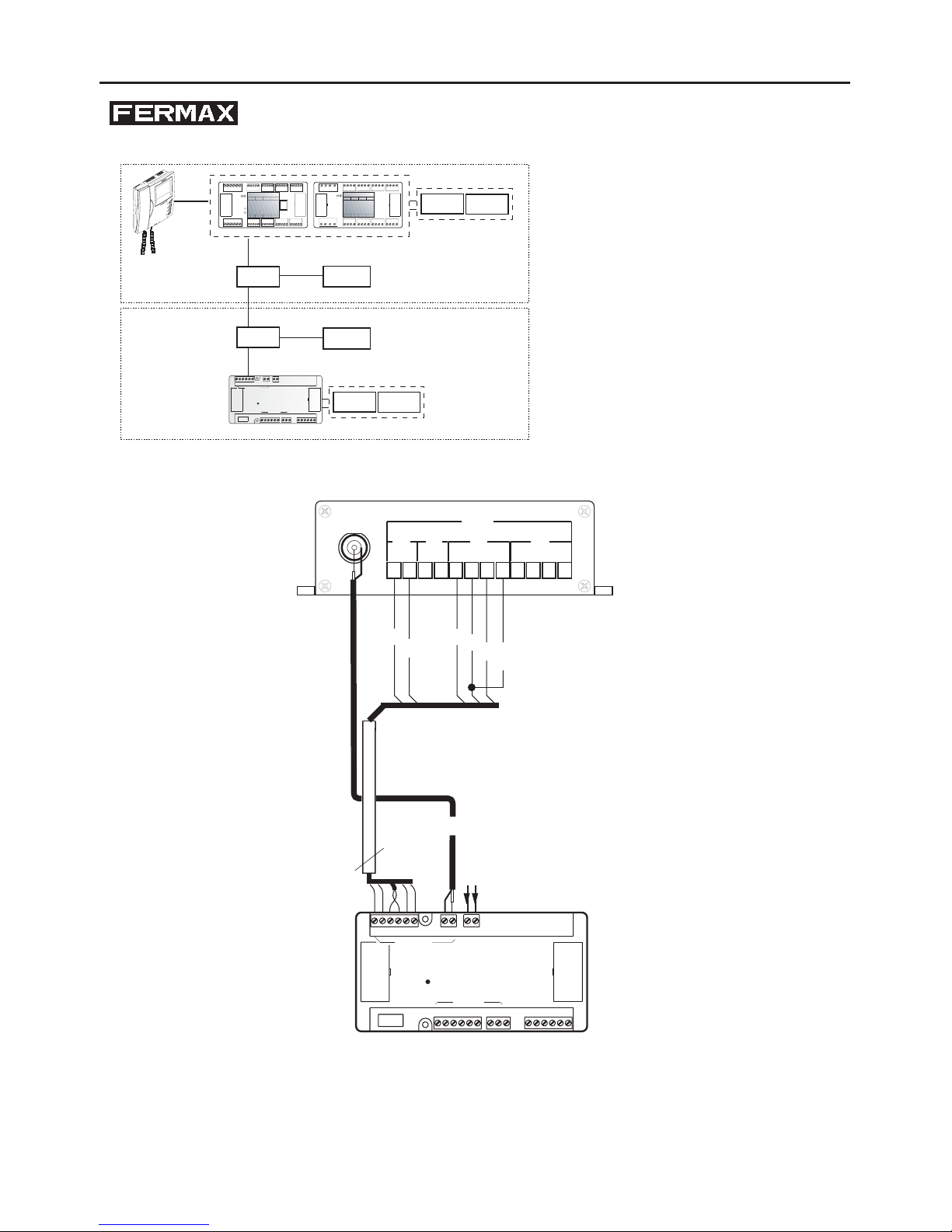
1. Panel Bus ................................................................................................... 10
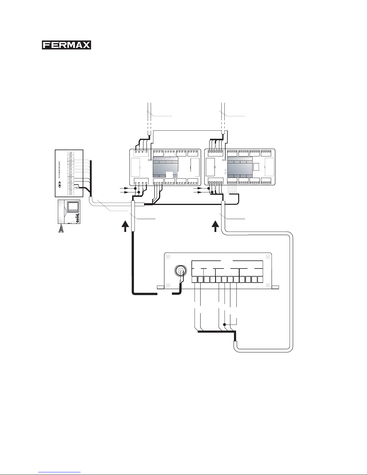
2. Decoder Bus ............................................................................................... 12
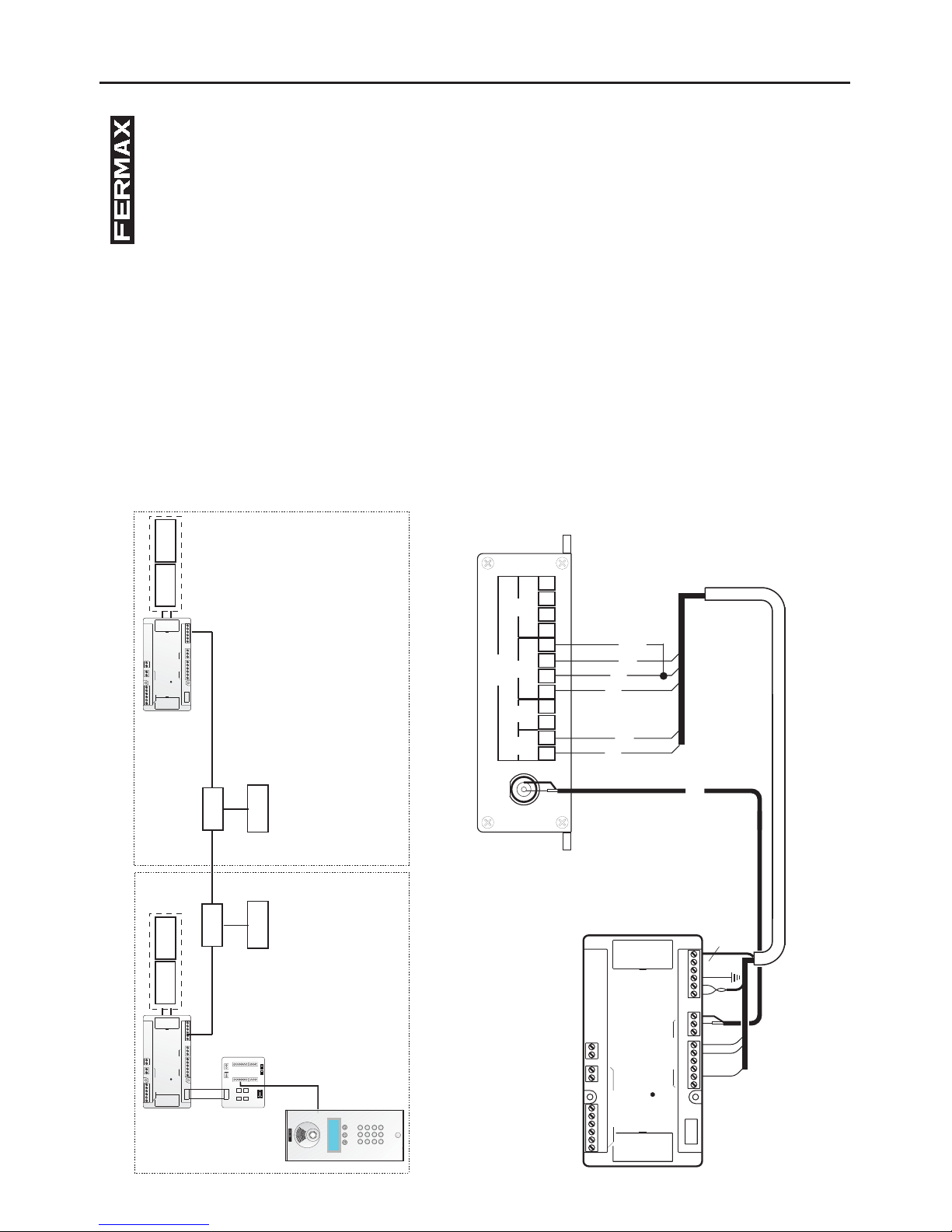
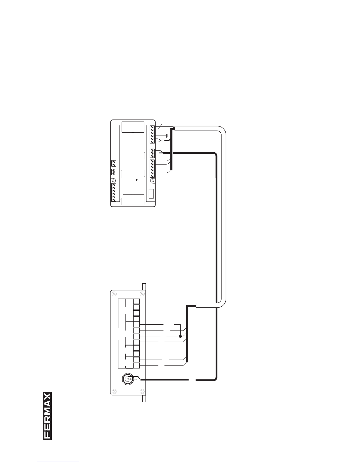
3. Central Unit Network ................................................................................... 14
INSTALLATION MANUAL
Table of Contents
Page 3

Page 4
Page 4

Page 5
The MDS Fibre Optic (FO) connection allows the transmission of audio, video and data signals from
the MDS system via FO cables to achieve distances above and beyond those permitted via the
electronic cable, in addition providing isolation against noise produced by nearby electrical systems
or that common in the case of large distances, providing isolation against electro-static charges
produced by storms.
It is comprised of a pair of elements: Transmitter (TX) installed on the entry panel side (origin of the
video signal) and receptor (Rx) installed on the monitor side (receives the video signal).
The connection can be used on any communication section of the MDS system.
- Digital panel connection to the central unit (Panel Bus).
- Decoder Bus.
- FXL: connection between central units.
Introduction
Page 5

Page 6
FEATURES
Fibre Optic.
o Connector: FC/PC.
o Fibre: Mono Mode.
o Maximum Distance: 5km.
Video.
o Connector: BNC 75-5.
o Video Signal:1Vpp (75 Ohm).
o Noise Signal Ratio (NSR) >67dB.
o Bandwidth: 5Hz – 10MHz.
Data.
o Connector: 2.5mm, 4 terminal grid.
o Protocol: RS-485.
o Speed:< 300Kbps.
o Operating Mode: full duplex.
Audio.
o Connector: 2.5mm, 4 terminal grid.
o Input/Output Impedance: 600 Ohm.
o Input/Output Level: 0dBm.
o Frequency Response: 10Hz – 20 KHz.
o Noise Signal Ratio: 80dB.
Contact.
o Connector: 2.5mm, 4 terminal grid.
o Input Contact: 0/5V opto-coupled. Contact Opening/Closing Transmission.
o Output Contact: 0.1A relay
Environmental Requirements.
o Operating Temperature: -20º C ~ +85º C
o Relative Humidity: 10% ~ 95%
Page 6

Page 7
Size: 132mm × 112mm × 34mm.
Power Supply: 5.8 Vdc, 3A (adaptor included 140 - 260 Vac.)
IMPORTANT NOTE: Two devices cannot be connected in cascade.
INSTALLATION
The fibre optic devices (transmitter/receptor) are powered at 5.8 Vdc using adaptors
supplied with the equipment.
The equipment can be installed on the wall (requires 4 screws for its installation). It
can also be placed on a platform which supports a weight of 5 Kg.
For both devices:
o Set up data, audio and contact conections on terminal grids D0, D1 and D3
respectively.
o Connect the video coxial cable to terminal V1 and the fibre optic cable to the FTRX port.
o Connect the power supplies provided and check that the PWR power supply led
(yellow) is on.
o The SYN fibre optic status indicator led should be off if connected correctly. If there
is any problem with the fibre optic connection it will light up.
Page 7
Page 8
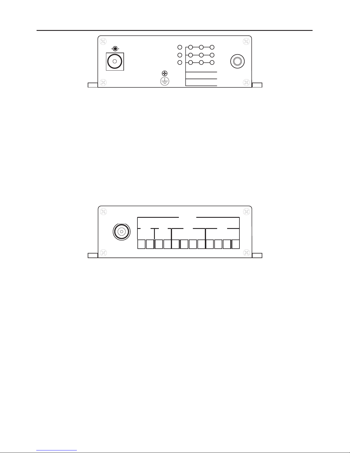
TRANSMITTER TX (1010)
Power Supply (POWER): 5.8 Vdc, 3A (adaptor included 140 - 260 Vac.)
Fibre Optic (FTRX).
LED Signalling:
o PWR (power supply): Power supply indicator led (yellow).
o SYN (fibre optic connection status indicator): red indicates incorrect reception.
In normal use it should be off.
o V1 (video): Correct video signal, the green led should be on.
o D1 (data): The green led should flash when it transmits or receives data.
PWR
POWER
5.8VDC/3A
+
SYN
V1
V2
V3
V4
D3
D4
D5
D0
D1
D2
FTRX
PORT
D0
12D112
12D23412D334
D0
12D112
DATA
V1
Video Input (V1): BNC 75-5.
D0: Data (RS-485).
o 1: SA (Panel Bus), D1 (Decoder Bus), A (Central Unit Network - FXL).
o 2: SB (Panel Bus), D2 (Decoder Bus), A (Central Unit Network - FXL).
D1: Do not use.
D2: Audio
o 1: Audio low (2)
o 2: Negative (-).
o 3: Audio high (6).
o 4: Negative (-).
D3: Potential Free Contact
o 1, 2 : relay output.
o 3, 4 : contact input.
Page 8
Page 9
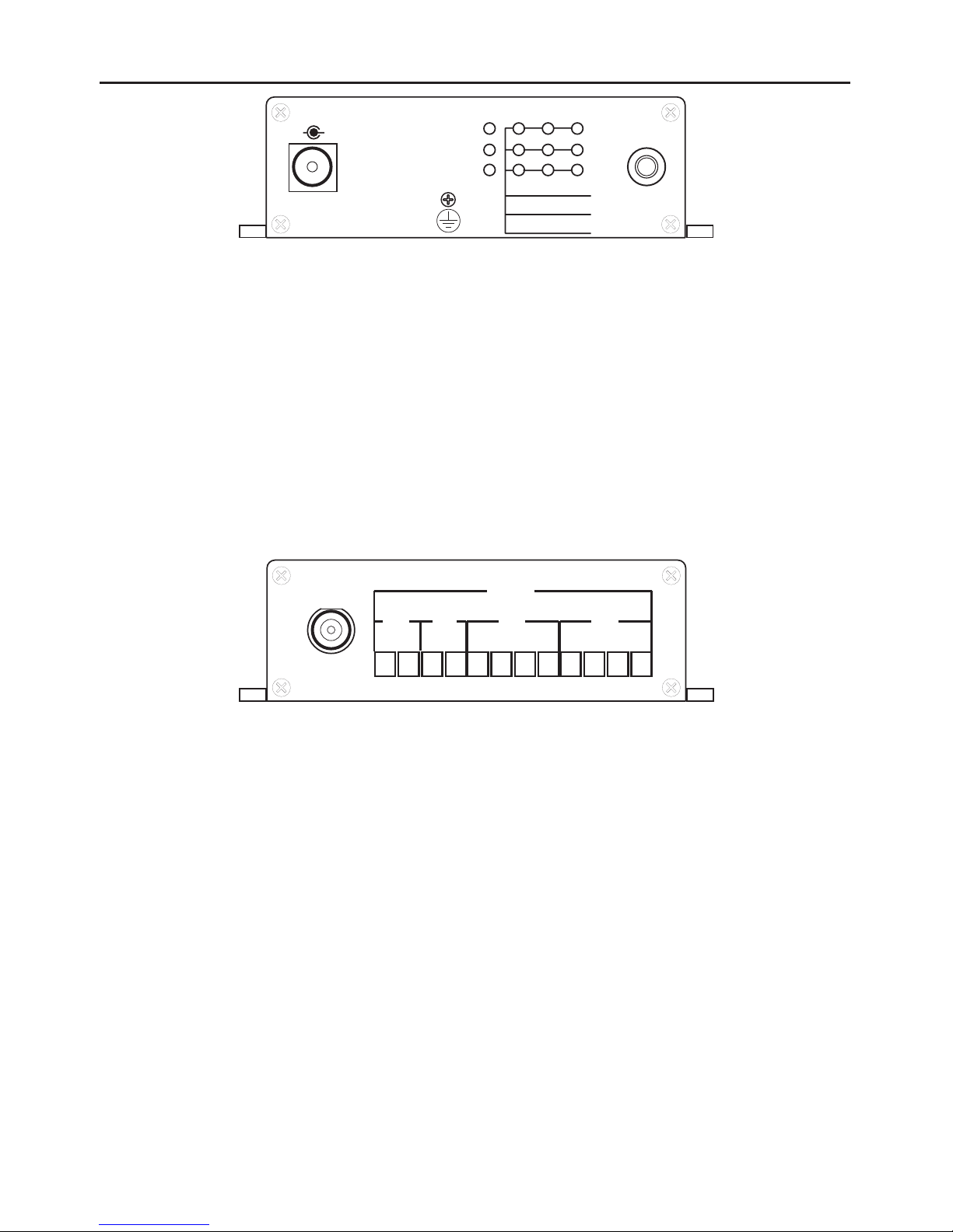
RX RECEPTOR (1001)
Power Supply (POWER): 5.8 Vdc, 3A (adaptor included 140 - 260 Vac.)
Fibre Optic (FTRX).
LED Signalling:
o PWR (power supply): Power supply indicator led (yellow).
o SYN (fibre optic connection status indicator): red indicates incorrect reception.
In normal use it should be off.
o V1 (video): Correct video signal, the green led should be on.
o D1 (data): The green led should flash when it transmits or receives data.
PWR
POWER
5.8VDC/3A
+
SYN
V1
V2
V3
V4
D3
D4
D5
D0
D1
D2
FTRX
PORT
D0
12D112
12D23412D334
D0
12D112
DATA
V1
Video Input (V1): BNC 75-5.
D0: Data (RS-485).
o 1: SA (Panel Bus), D1 (Decoder Bus), A (Central Unit Network - FXL).
o 2: SB (Panel Bus), D2 (Decoder Bus), A (Central Unit Network - FXL).
D1: Do not use.
D2: Audio
o 1: Audio high (6).
o 2: Negative (-).
o 3: Audio low (2)
o 4: Negative (-).
D3: Potential Free Contact
o 1, 2 : relay output.
o 3, 4 : contact input.
Page 9
Page 10
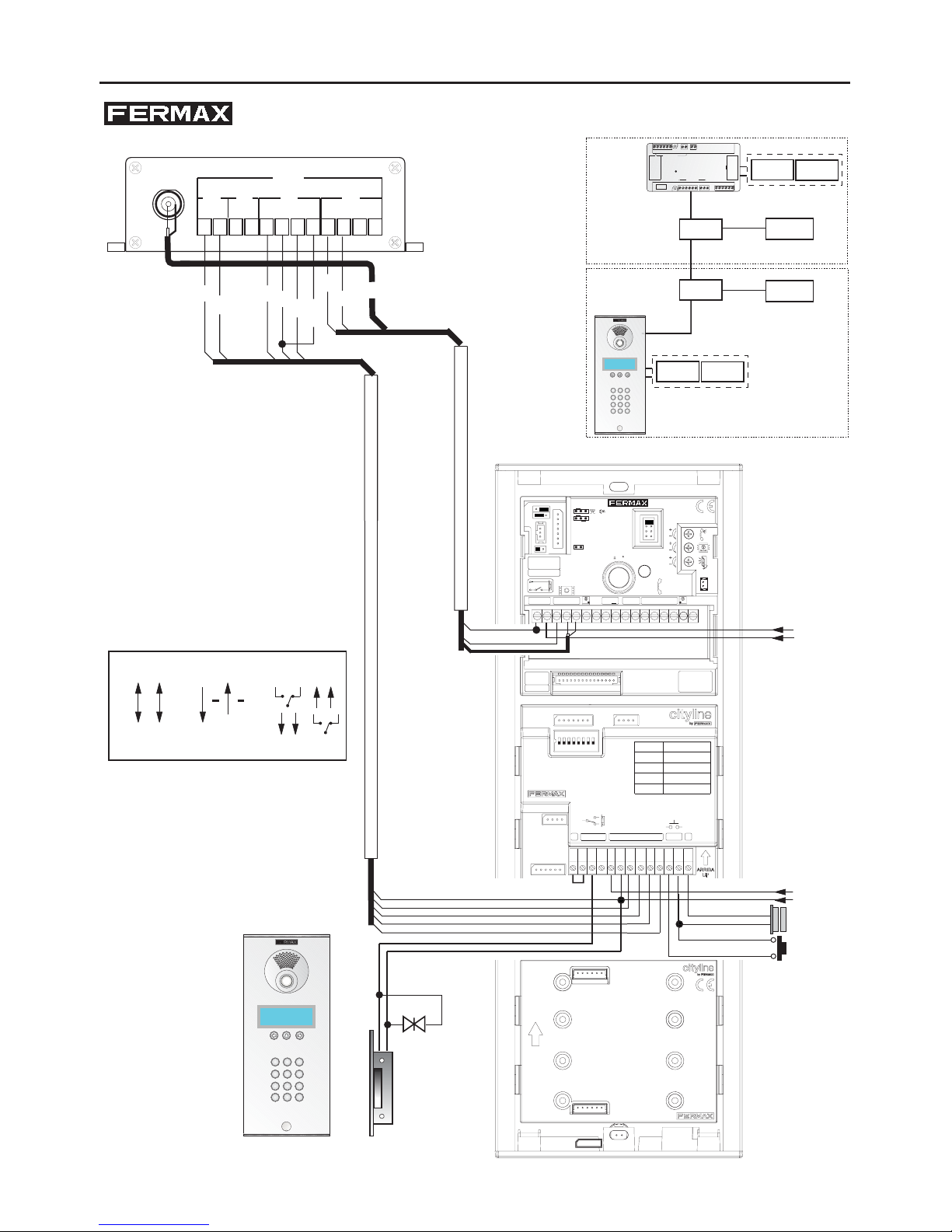
DIAGRAMS: 1. PANEL BUS
VARISTOR
PC CONNECTOR
CONECTOR DE PC
12
6
7
8
51
2
4
3
LECTOR DE PROXIMIDAD
PROXIMITY READER
KEY PAD TERMINALS
CONECTOR DE TECLADO
AMPLIFIER
CN2
CN3
CN4
AMPLIFICADOR
CN5
DESCRIPCIÓN
DESCRIPTIONCONNECTOR
CONECTOR
-
+12
CK
DT
-
+
A
B
D
C
-
+
SB
SATC
CP
+12
3
6
2
1
DISPLAY DIGITAL MDS
MDS PANEL BUS
BUS DE PLACAS MDS
C
NC
NO
6
SB
2
SA
SP
CN2
CN3
SW1
CN4
CN5
MDS DIGITAL DISPLAY
COD.99627
-
+
BS
-
NO
NC
C
+
EXIT
NO
C
MIC
NO
C
~
D
C
B
A
AMPLIFICADOR 4+N
4+N AMPLIFIER
AMPLIFICATEUR 4+N
4+N VERSTÄRKER
CT
V
M
+18
-
PAN & TILT
JP4
JP1
CN1
Cp1
~
1236
Cp2
CN4
/
F / U
L +
Cp1
L -
1/N
~
~
Aliment.
P.Supply
12 Vac/Vdc
Aliment.
P.Supply
18 Vdc
TEST
ENTRADA/INPUT
ARRIVÉE/EINTRITT
CN1
ARRIBA/UP
HAUT/OBEN
SALIDA/OUTPUT
SORTIE/AUSGANG
CN2
MÓDULO TECLADO
KEYPAD MODULE
MODULE CLAVIER
TASTATURMODUL
JP3
12
6
SB
2
SA
-
+
NO
NC
C
+
BS
-
SP
12 Vdc
+
-
D0
12D112
12D23412D334
D0
12D112
DATA
SA
SB
V1
2
6
-
+18
CT
COAX
D2
AUDIO
D0
DATA
D3
TX
18 Vdc
+
-
B
26
FXLPANEL 0
2+-SBSA CT6 VM AB GA
12Vdc
REF. 2405
UNIDAD CENTRAL MDS
MDS CENTRAL UNIT
DECODERS
D2 D1+-M V
-
+
G
18 Vdc
12 Vdc
18 Vdc
12 Vdc
TX
RX
5.8 Vdc
5.8 Vdc
987
654
321
A
B
0
1. BUS PLACAS / PANELS BUS
1B
1A
987
654
321
A
B
0
1A. BUS PLACAS / PANELS BUS
1A
Page 10
Page 11
B
26
FXLPANEL 0
2+-SBSA CT6 VM AB GA
12Vdc
REF. 2405
UNIDAD CENTRAL MDS
MDS CENTRAL UNIT
DECODERS
D2 D1
+-
M V
-
+
G
12 Vdc
+
-
D0
12D112
12D23412D334
D0
12D112
DATA
RX
STAIRS LIGHT RELAY
RELE LUZ DE ESCALERA
REF. 2013
81+V3 4
NoC Nc
LE
+
Max. 2A
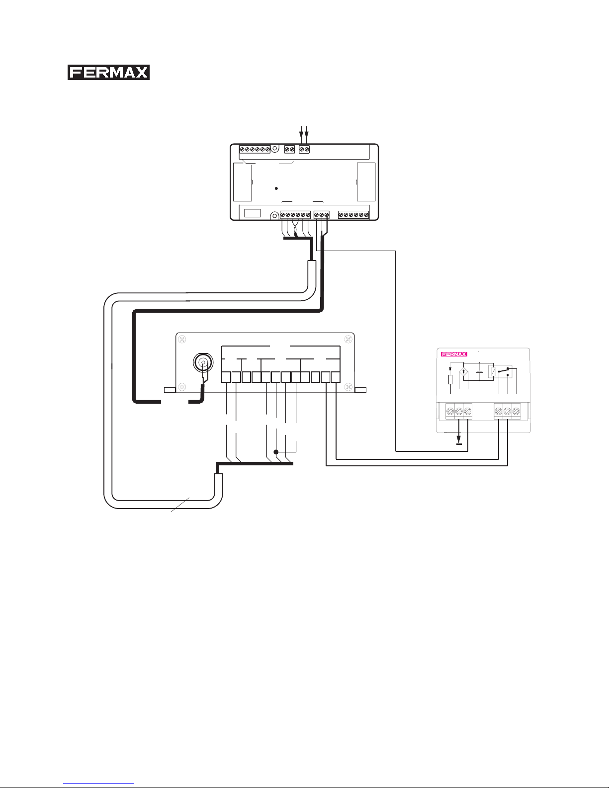
1B. BUS PLACAS / PANELS BUS
1B
Ref.5918
SA
SB
V1
6
2
-
COAX
Page 11
Page 12
DIAGRAMS: 2. DECODER BUS
B
26
FXLPANEL 0
2+-SBSA CT6 VM AB GA
12Vdc
REF. 2405
UNIDAD CENTRAL MDS
MDS CENTRAL UNIT
DECODERS
D2 D1
+-
M V
-
+
G
12 Vdc
+
-
D0
12D112
12D23412D334
D0
12D112
DATA
TX
V1
TX
RX
5.8 Vdc
5.8 Vdc
B
26
FXLPANEL 0
2+-SBSA CT6 VM AB GA
12Vdc
REF. 2405
UNIDAD CENTRAL MDS
MDS CENTRAL UNIT
DECODERS
D2 D1+-M V
-
+
G
18 Vdc
12 Vdc
TELEFONOS
D2
BUS
+D1-
62
PGM
12116432423
3
D1
BUS
26
D2
3
5
-
-+
V
6466217342
13261464 423 6
6 38614213421
REF. 2425
BUS
BUS
-+
V
VM
-
M
+
-
V
MV
- +V-+
MMV
-
+
+M-
V M+-V M+-V M
+
MV
-
+ -
V
3421
REF. 2419
VIDEO
756 8
18 Vdc
12 Vdc
2. BUS DECODERS / DECODER BUS
2B
2A
Ref.5918
D1
D2
2
6
-
COAX
2A
Page 12
Page 13
Ref.5919 Ref.5918
M
+
M1
Ref.5920
VMVVMMVMV
Ref.5919
+ - -+ -+ - + + -
REF. 2419
M5
-
BUS
BUS
M V
5
1
V
-
+M-
V
876
VIDEO
32 4
M+V
+ -M-V+MV-
M7M6
6432162341436216231
6
D22D1
+
4
Ref.5918
M3M2 M4
2
TELEFONOS
REF. 2425
M5
-
62
D2
5
BUS
PGM
1
BUS
-
-D1+
V
643
867
32
4
14623612 4314623
M7M6
DECODER 8
Ref.2425
1
F2
F1
+
M
-
V
4
3
2
1
CT
6
CN1
F2
F1
V
M
M8M8
D0
12D112
12D23412D334
D0
12D112
DATA
RX
DISTRIBUTOR
Ref.2419
DISTRIBUIDOR
M4
M2
M3
D1
D2
V1
6
2
-
COAX
18 Vdc
+
-
12 Vdc
+
-
2B. BUS DECODERS / DECODER BUS
2B
Page 13
Page 14
DIAGRAMS: 3. CENTRAL UNIT NETWORK (FXL)
RX
TX
5.8 Vdc
18 Vdc
12 Vdc
B
26
FXLPANEL 0
2
+-
SBSA CT6 VM AB GA
12Vdc
REF. 2405
UNIDAD CENTRAL MDS
MDS CENTRAL UNIT
DECODERS
D2 D1
+-
M V
-
+
G
CN1
CN2
CN8
CN7
SA
SB
CT
M
V
6
2
-
+
CN3
SA
M
CT
V
SB
6
2
-
+
CN4
CN5
CN6
OUT
IN
+- + -
SW1
SW2
ON ON
5.8 Vdc
18 Vdc
12 Vdc
B
26
FXLPANEL 0
2
+-
SBSA CT6 VM AB GA
12Vdc
REF. 2405
UNIDAD CENTRAL MDS
MDS CENTRAL UNIT
DECODERS
D2 D1
+-
M V
-
+
G
D0
12
D1
12
12
D2
3412
D3
34
D0
12
D1
12
DATA
TX
987
654
321
A
B
0
3. RED DE CENTRALES / CENTRAL UNITS NETWORK
3A 3B
3A. RED DE CENTRALES / CENTRAL UNITS NETWORK
3A
A
B
V1
2
-
6
-
COAX
B
26
FXLPANEL 0
2
+-
SBSA CT6 VM AB GA
12Vdc
REF. 2405
UNIDAD CENTRAL MDS
MDS CENTRAL UNIT
DECODERS
D2 D1
+-
M V
-
+
G
malla /
shield
Page 14
Page 15
D0
12
D1
12
12
D2
3412
D3
34
D0
12
D1
12
DATA
RX
3B. RED DE CENTRALES / CENTRAL UNITS NETWORK
B
26
FXL
PANEL 0
2
+-
SBSA
CT
6
VM
AB
GA
12Vdc
REF. 2405
UNIDAD CENTRAL MDS
MDS CENTRAL UNIT
DECODERS
D2 D1
+-
M V
-
+
G
malla/
shield
A
B
V1
6
-
2
-
COAX
3B
Page 15

Page 16
Page 16

Page 17
Page 17

www.fermax.com.
 Loading...