

Page 1

PLACA VDS
VDS OUTDOOR PANEL
PLATINE VDS
VDS TÜRSTATION
PLACA VDS
MANUAL DE INSTALADOR
INSTALLER’S MANUAL
MANUEL D´INSTALLATION
INST ALLATIONSHANDBUCH
MANUAL DO INSTALADOR
ESPAÑOL
ENGLISH
FRANÇAIS
DEUTSCH
PORTUGUÊS
Page 2

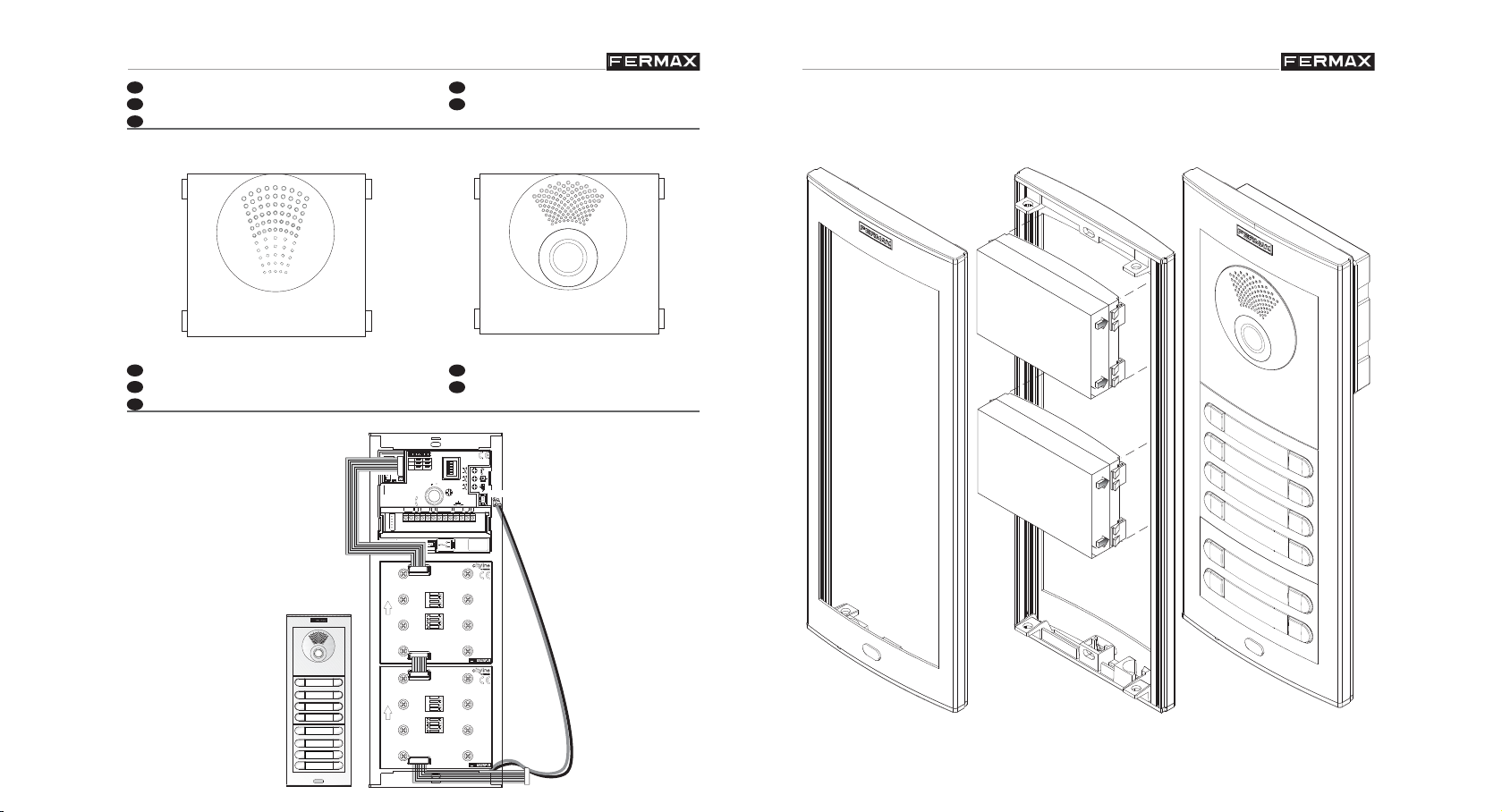
VDS Panels
VDS Panels
VDS Panels
VDS Panels
E
EN
F
D
P
EN
E
F
D
P
ENHORABUENA POR DISPONER DE UN PRODUCTO DE CALIDAD!
Fermax desarrolla y fabrica equipos de prestigio que cumplen los más altos estándares
de diseño y tecnología. Esperamos disfrute de sus funcionalidades.
CONGRATULATIONS ON PURCHASING THIS QUALITY PRODUCT!
Fermax develops and manufactures reputable equipment which fulfi ls the highest design
and technology standards.We hope you enjoy its range of functions.
FÉLICITA TIONS ! VOUS VENEZ D’ACQUÉRIR UN VÉRIT ABLE PRODUIT DE QUALITÉ!
Fermax développe et fabrique des équipements de prestige qui répondent aux normes de
design et technologie les plus développées.Nous espérons que vous profi terez pleinement
de toutes ses fonctions.
WIR GRATULIEREN IHNEN ZUM KAUF DIESES QUALITÄTSPRODUKTS!
Fermax entwickelt und fabriziert hochwertige Anlagen, die den höchsten Technologie- und
Designstandards entsprechen. Überzeugende Funktionalität für Ihr Eigenheim!
PARABÉNS POR DISPOR DE UM PRODUTO DE QUALIDADE!
Fermax desenvolve e fabrica equipamentos de prestígio que cumprem com os mais altos
padrões de desenho e tecnologia. Esperamos que desfrute das suas funcionalidades.
Cod. 97616 V07_14
INDICE - INDEX - SOMMAIRE - INHALT - INDICE
AMPLIFICADOR ADS/VDS .................................................................... 4
Instalación del amplifi cador .............................................. ........... 4
Conectores / Ajustes / Reset a valores de fábrica ........... ........... 6
Precableado ................................................................................. 17
Características Técnicas .............................................................18
Cableado ......................................................................................19
ADS/VDS AMPLIFIER ............................................................................ 4
Amplifi er installation ......................................................... ........... 4
Connectors / adjustment / Reset a valores de fábrica ....... .......... 6
Internal wiring ...............................................................................17
Technical Features ......................................................................18
Wiring ........................................................................................... 19
AMPLIFICA TEUR ADS/VDS ................................................................... 4
Installation du amplifi cateur ............................................... .......... 4
Connecteurs . / Réglages / Reset a valores de fábrica .... .......... 6
Precâblage ................................................................................... 17
Caractéristiques techniques ............................................. ...........18
Câblage .......................................................................................19
ADS/VDS-VERSTÄRKER ....................................................................... 4
Installation des Netzgeräts ................................................ .......... 4
Anschlüsse / Einstellungen / Nullstellung auf werksseitige ..........6
Parameter .................................................................................... 6
Vorverkabelung ............................................................................ 17
Technische Eigenschaften ............................................................18
Verkabelung ................................................................................. 19
AMPLIFICADOR ADS/VDS .................................................................... 4
Instalação do amplifi cador ..................................... ........... ........... 4
Conectores / Ajustes / Reset para valores de fábrica ................. 6
Pré-cablagem ................................................................... ...........17
Características Técnicas .............................................................18
Cablagem ....................................................................................19
Pag 3Pag 2
Page 3
VDS Panels
VDS Panels
VDS Panels
VDS Panels
E
AMPLIFICADOR ADS/VDS
EN
F
D
P
E
EN
F
D
P
AMPLIFICATEUR ADS/VDS
AMPLIFICADOR ADS/VDS
ADS/VDS AMPLIFIER
ADS/VDS VERSTÄRKER
VIDEOAUDIO
INSTALACIÓN PLACA
INSTALLATION PLATINE
INSTALAÇÃO DO PLACA
JP2
JP3
JP4
ALIMENTACION
POWER SUPPLY
-+
ARRIBA/UP
HAUT/OBEN
ARRIBA/UP
HAUT/OBEN
CN2
TARJETERO
TAG HOLDER
PANEL INSTALLATION
INSTALLATION TÜRTATION
AMPLIFICADOR - VERSTÄRKER
VDS
CN1
AMPLIFICATEUR - AMPLIFIER
JP2
ON
SLAVE
MASTER
JP3
LEDS ON
JP4
CT OUT CT IN
CN2
OUTPUT
CN1
PROG
SW1
DL2
SW1
DL2
18V
DC
CN3
-
+
L
STATUS
CN3
18 Vdc
MONITOR TEST
CN7
INPUT
OUTPUT
INPUT
OUTPUT
AUDIO
A
LEDS OFF
B
C
D
E
IDIOMA
PAN & TILT
LANGUAGE
10
CAM
+12
M
V
CN1
CN2
CN1
CN2
C
C
EXIT
NCNO
BS
NO
NC
MODULE BOUTON-POUSSOIR
MODULE BOUTON-POUSSOIR
CT
-
S
MÓDULO PULSADOR
PUSH-BUTTON MODULE
MÓDULO PULSADOR
PUSH-BUTTON MODULE
VERSION
TASTEMODUL
TASTEMODUL
MIC
MIC
:
Pag 5Pag 4
Page 4
VDS Panels
VDS Panels
VDS Panels
VDS Panels
E
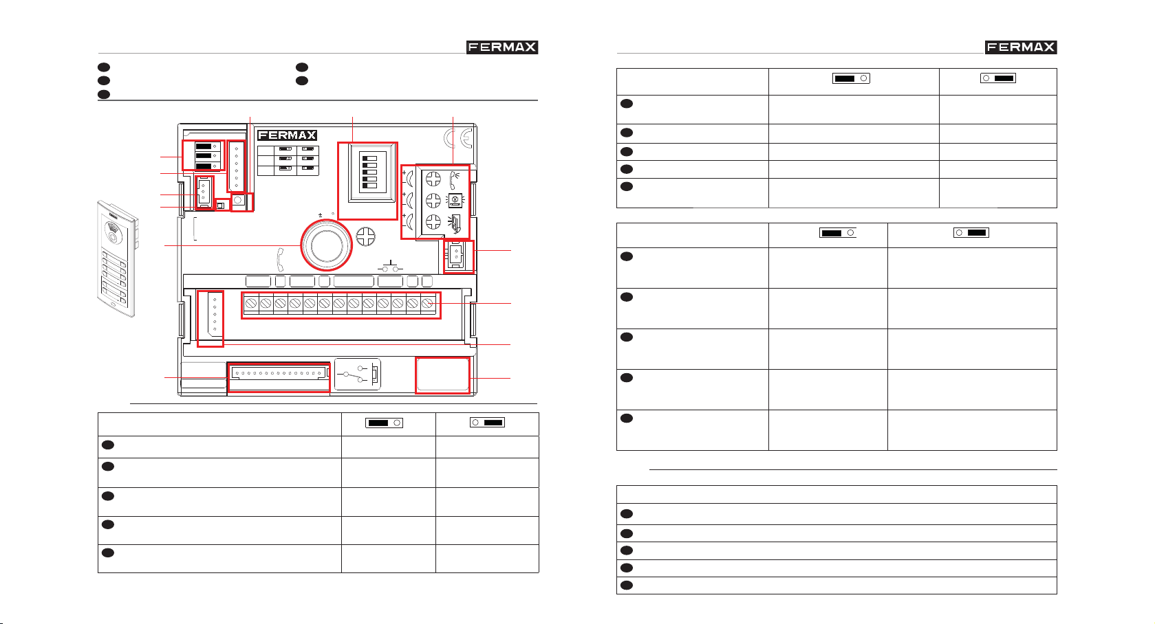
CONECTORES/AJUSTES EN CONNECTORS/ADJUSTMENT
F
D
P
E
EN
F
D
P
E
EN
F
D
P
E
EN
F
D
P
E
EN
F
D
P
CONNECTEURS/RÉGLAGES
ANSCHLÜSSE/EINSTELLUNGEN
CONECTORES/ AJUSTES
A)
B)
C)
D)
E)
F)
JP2
JP3
JP4
CN2
CN2
TARJETERO
TAG HOLDER
CN3
STATUS
CN3
ALIMENTACION
POWER SUPPLY
-+
18 Vdc
DL2
G)
CN1
JP2
JP3
JP4
CN1
SW1
DL2
SW1
18V
DC
+
CN7
MASTER
LEDS ON
CT OUT CT IN
OUTPUT
PROG
-
L
MONITOR TEST
LEDS OFF
CAM
V
SLAVE
M
H)
AMPLIFICADOR - VERSTÄRKER
VDS
AMPLIFICATEUR - AMPLIFIER
A
B
C
D
E
PAN & TILT
10
+12
C
C
IDIOMA
LANGUAGE
NCNO
BS
NO
NC
ON
EXIT
-
S
AUDIO
CT
VERSION
I )
:
A)
JP2
Selección Placa Principal / Placa Secundaria
Main Panel/Secondary Panel Selection
Placa Principal Placa secundaria
Main Panel Secondary Panel
(*)
MIC
J )
K )
L )
M)
JP3
Leds cámara
Camera LEDs
DEL de la caméra
Leuchtdioden der Kamera
Leds de câmara
JP4
CT: Activación cámara/
salida auxiliar
CT: Camera activation/
auxiliary output
CT : Activation caméra /
sortie auxiliaire
CT: Kameraaktivierung/
Nebenausgang
CT: Activação da câmara/
saída auxiliar
B)
encendidos cuando la camara
apagados siempre
está activada
ON when the camera is active
always off
ON quand la caméra est activée toujours éteintes
ON wenn die Kamera aktiv is immer ausgeschaltet
ON quando a câmara está
sempre apagados
activada.
CT: salida 11 Vdc CT: entrada - Conectar 12 Vdc
para activar permanentemente
cámara+ leds
CT: 11 Vdc output CT: input - Connect 12 Vdc to
permanently activate camera +
LEDs
CT : sortie11 Vcc CT : entrée - Connecter 12 Vcc
pour activer en permanence
caméra + leds
CT: 11 VDC Ausgang CT: Eingang - 12 VDC NG ans-
chließen um Kamera und LEDs
permanent zu aktivieren
CT: saída de 11 VDC CT: entrada - Ligar 12 VDC para
activar permanentemente a
câmara+ LEDS
Sélection de la platine principale / platine
Platine principale Platine secondaire
secondaire
Auswahl Haupttürstation / Nebentürstation
Selecção de Placa Principal / Placa
Haupttürstation Nebentürstation
Placa Principa
l Placa Secundária
Secundária
(*) Confi guración por defecto: Placa Principal - Default Confi guration: Main Panel - Confi guration par défaut
: platine principale - Standardkonfi guration: Haupttürstation - Confi guração por defeito: Placa Principal
CN1
Conexión pulsadores modulares, teclado, display.
Connection modular buttons, keypad, display.
Connexion boutons-poussoirs modulaires, clavier, affi chage.
Anschluss Tastenmodule, Tastatur, Display.
Ligação do botões modulares, teclado, display.
Pag 7Pag 6
Page 5

VDS Panels
VDS Panels
VDS Panels
VDS Panels
C)
E
EN
F
D
P
E
EN
F
D
P
E
EN
F
D
P
10º
10º
10º
10º
E
EN
F
D
P
E
EN
F
D
P
E
EN
F
D
P
F)
CN2
Conexión iluminación
tarjeteros y pulsadores
Connection card holder
and button lighting
Connexion éclairage
boutons-poussoirs et
porte-étiquettes
Anschluss Tasten- und
Infomodul-Beleuchtung
Ligação de iluminação
dos porta-cartões e
botões
D)
DL2
Led Diagnóstico
Diagnostic Led
Diagnostic Del
Diagnose-LED
Led diagnóstico
E)
L+/L- CP
Luz tarjetero pulsador
Cardholder Backlight
Lumière porte-étiquettes bouton-
poussoir
Común de pulsadores
Common Button Wire
Connecteur commun
de boutons-poussoirs
Beleuchtung Taste Infomodul Gemeinsamer Draht
der Klingeltasten
Luz do porta-cartões do botão Comum de botões
Si existe un cortocircuito entre + y L, al llamar desde placa
emite una serie de destellos cortos
If there is a short circuit between + and l, when a call is made
from the panel, it emits a series of short fl ashes
S’il existe un court-circuit entre + e L lors d’un appel de la
platine, elle émet una série de brefs clignotements
Falls ein Kurzschluss zwischen + und L bei der Durchführung
eines Anrufs, blinkt diese mehrmals kurz auf
Se existir um curto-circuito entre + e L, ao realizar uma
chamada a partir da placa emite luz intermitente rápida
Pan&Tilt (±10º)
CN7
Video Test monitor
Video test monitor
Écran de Test Vidéo
Video Testmonitor
Video Test monitor
Conector de test y programación de monitores
Test and monitor programming connector
Connecteur de test et programmation d’écrans
Testanschluss und Monitorprogrammierung
Conector de teste e programação de monitores
G)
SW1
Mapeado: botón para entrar en modo programación de pulsadores. Ver manual
“Mapeado”
Mapping: button to enter button programming mode. See manual ‘Mapping’
Mappage : bouton pour entrer en mode programmation de boutons-poussoirs. Voir
manuel « Mappage »
Mapping: Programmiertaste der Klingeltasten Siehe Handbuch“Mapping”
Mapeamento: botão para aceder ao modo de programação de botões. Ver o manual
“Mapeamento”
H)
Selección del idioma del mensaje de «puerta abierta».
Ver CODIFICACIÓN al fi nal de este manual.
Select language for «open door» message.
See CODIFICATION at the end of this manual.
A
B
C
D
E
ON
Sélection de la langue du message « porte ouverte ».
Voir CODIFICATION à la fi n de ce manuel.
Enfoque la telecámara
Focus the camera
Réglez la caméra vidéo
Richten Sie die Kamera aus
Foque a telecâmara.
Sprachwahl der Meldung «Tür offen».
Siehe KODIERUNG am Ende dieses Handbuchs.
Selecção da língua da mensagem de «porta aberta».
Ver CODIFICAÇÃO no fi nal deste manual..
Pag 9Pag 8
Page 6
VDS Panels
VDS Panels
VDS Panels
VDS Panels
E
EN
F
D
P
E
EN
F
D
P
I)
F
D
E
EN
F
D
P
E
EN
P
Ajuste audio
Adjust the audio
Réglez le volume
Audioeinstellung
Ajuste o áudio
“puerta abierta”
“open door”
« porte ouverte »
“Tür offen”
“porta aberta”
J)
MIC
Conexión micrófono (micrófono ubicado en el perfi l inferior de la placa)
Microphone connection (microphone located in the lower panel profi le)
Connexion microphone (microphone placé sur le profi l inférieur de la platine)
Mikrofonanschluss (Mikrofon befi ndet sich am unteren Profi l der Türstation)
Ligação do microfone (microfone localizado no perfi l inferior da placa)
K)
Conectores Placa:
• Bornas de video, (coaxial).
V: vivo
M: malla
Ct: activación telecamara (1 1 Vdc)
• Bornas de Conexión del sistema:
+, -: alimentación (18 Vdc).
L: bus de datos.
+12: salida12 Vdc (0,4 A. max).
C, NO, NC: contactos relé
(conexión abrepuertas)
BS, -: pulsador zaguán.
S: activación del cambiador
Panel Connectors:
Video terminals (coaxial):
•
V: live
M: shield
Ct: camera activation (11 Vdc)
• System connection terminals:
+, -: power supply (18 Vdc).
+12: 12 Vdc output.
L: data bus.
C, NO, NC: relay contacts
(door-opener connection)
BS, -: entrance hall button.
S: activation of the exchanger
Connecteurs platine:
Bornes vidéo (câble coaxial).
•
V : vif
M : maille
Ct : activation caméra (11 Vdc)
• Bornes de raccordement du
système.
+, - : alimentation (18 Vcc).
L : bus de données.
+12: 12 Vcc
C, NO (no), NC (nf) : contacts
relais (connexion gâche
électrique)
BS, - : bouton-poussoir
vestibule.
S : activation de l’échangeur.
Conectores de Placa:
Terminais de vídeo (coaxial).
•
V: vivo
M: malha
Ct: activação telecâmara (11 Vdc)
• Terminais de ligação do sistema:
+, - : alimentação (18 Vdc).
L: bus de dados.
+12: 12 Vdc
C, NA, NC: contactos de relé
(ligação do trinco)
BS, -: botão para abrir a porta do
vestíbulo.
S: activação do comutador
Anschlüsse Türstation:
Video-Klemmen (Koaxial)
•
V: Kern
M: Schirm
Ct: Aktivierung der Kamera (11
VDC)
• Anschlussklemmen des
Systems:
+, - : Stromversorgung (18 VDC)
L: Daten-Bus
+12: 12 V Gleichstrom
C, NO, NC: Relais-Kontakte
(Verbindung Türöffner)
BS, -: Drucktaste Flur
S: Aktivierung des Umschalters.
Pag 11Pag 10
Page 7

VDS Panels
VDS Panels
VDS Panels
VDS Panels
L)
E
EN
F
D
P
E
EN
F
D
P
E
EN
F
D
P
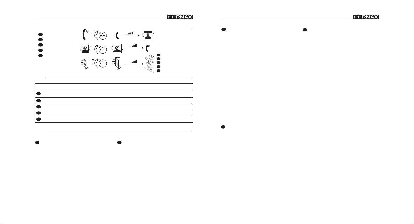
CN3: Conexión leds de estado. De gran utilidad para personas discapacitadas,
permite conectar leds que informan del estado de la comunicación.
L2, L3, L4: entregan un negativo cuando se realiza la acción correspondiente, activando el led conectado entre “Lx” y “+”:
CN3: Connection Status Leds V ery useful for disabled people, allowing leds
to be connected which provide information on communication status.
L2, L3, L4: generates a negative signal when the corresponding action is
taken, activating the led connected between “Lx” and “+”:
CN3 : connexion DEL d’état. Très utile pour les personnes handicapées, il
permet de raccorder des DEL indiquant l’état de la communication.
L2, L3, L4 : transmettent un négatif lorsque l’action correspondante est
effectuée, en activant la DEL raccordée entre « Lx » et « + ».
CN3: Anschluss LED-Statusanzeige Von großem Nutzen für behinderte
Personen; ermöglicht das Anschließen von LEDs, die über den Zustand
der Verbindung informieren.
L2, L3, L4: übermitteln einen Negativstrom, wenn der entsprechende Vorgang ausgelöst wird, worauf die angeschlossene LED zwischen “Lx” und
“+” aktiviert wird:
CN3: Ligação dos LEDS de estado. De grande utilidade para pessoas
defi cientes, permite defi cientes que informam do estado da comunicação.
L2, L3, L4: entregam um negativo quando se realiza a acção
correspondente, activando o led ligado entre «Lx» y «+»:
L2 L3 L4
Led de comunicación
Communication Led
DEL de communication
LED Sprechverbindung
LED de comunicacão
M)
Versión del amplifi cador
Amplifi er version
Version de l’amplifi cateur
Lautsprecherversion
Versão do amplifi cador
Led de llamada Led apertura de puerta
Call Led Lock Release Led
DEL d’appel DEL ouverture des portes
LED Anruf LED Türöffnung
LED de chamada ED abertura de porta
L1
L2
L3
+
L4
L4
Pag 13Pag 12
Page 8

VDS Panels
VDS Panels
VDS Panels
VDS Panels
E
RESTAURAR A VALORES DE FÁBRICA: Reset
D
EN
F
El amplifi cador VDS dispone de la función de «Reset» que permite restaurar los
parámetros programados (tiempo apertura de puerta y zaguán, códigos de acceso,
mapeado) a valores de fábrica.
RESET Mapeado
1º- Resetear el amplifi cador: quitar alimentación.
2º- Con el botón SW1 pulsado, dar alimentación y mantener pulsado el
botón SW1 hasta escuchar un sonido de confi rmación de reset.
RESET desde placas de teclado
Los pasos a realizar para restaurar los valores de fábrica son los siguientes:
1º- Resetear el amplifi cador: quitar alimentación.
2º- Dar alimentación, y en los primeros 60 segundos teclear el código
A708B9. Tras esta pulsación sonará un pitido largo, confi rmado la restau-
ración de los valores de fábrica.
RESTORE DEFAULT VALUES: RESET
The VDS amplifi er has a ‘Reset’ function which can be used to restore program-
med default parameters (door and hall lock-release time, access cods, mapping).
Mapping RESET
1.- Reset amplifi er: disconnect power supply
2.- Press the SW1 button, connect power supply and keep SW1 button
pressed until you hear the reset confi rmation sound.
RÉCUPÉRATION AUX VALEURS PAR DÉFAUT : REMISE À ZÉRO
L’amplifi cateur VDS dispose de la fonction « Remise à zéro » qui permet de rétablir
les paramètres programmés (durée d’ouverture des portes et hall, codes d’accès,
mappage) sur les valeurs par défaut.
RESET Mappage
1º- Remettre à zéro l’amplifi cateur : Couper l’alimentation.
2º- En maintenant le bouton SW1 enfoncé, alimenter le dispositif jusqu’à ce
qu’un avertissement sonore de confi rmation de la remise à zéro soit émis.
REMISE À ZÉRO à partir des platines à clavier
Les étapes à effectuer pour récupérer les valeurs par défaut sont les suivantes :
1º- Remettre à zéro l’amplifi cateur : Couper l’alimentation.
2º- Au cours des 60 premières secondes, composer le code A708B9. A la
suite de cette saisie, un long bip sera émis ; il confi rmera la récupération
des valeurs par défaut.
WIEDERHERSTELLUNG DER WERKSSEITIGEN PARAMETER:
NULLSTELLUNG
Der VDS-Verstärker verfügt über eine Reset-Funktion, die es ermöglicht die
werksseitig programmierten Parameter wieder herzustellen (Türöffnungszeit und
Treppenhausbeleuchtung, Zutrittskodes, Mapping).
Mapping NULLSTELLUNG
1. Nullstellung des Verstärkers: Stromversorgung unterbrechen.
2. SW1-T aste gedrückt halten, Stromzufuhr wiederherstellen ohne die SW1Taste los zulassen bis ein Piepton die Nullstellung bestätigt.
RESET from keypad panels
To restore the default values, follow the steps below:
1.- Reset amplifi er: disconnect power supply
2.- Connect power supply and within the fi rst 60 seconds, enter the
codeA708B9. After entering the code, a prolonged beep will sound to
confi rm the restoration of default values.
NULLSTELLUNG über Türstationen mit Tastatur
Schritte, zur Wiederherstellung der werksseitig einprogrammierten Parameter:
1. Nullstellung des Verstärkers: Stromversorgung unterbrechen.
2. Nullstellung des Verstärkers: Stromversorgung wiederherstellen und
innerhalb von 60 Sekunden den Kode A708B9 eingeben.Nach der Kodeeingabe ertönt ein langer Piepton zur Bestätigung der Wiederherstellung
der werksseitig einprogrammierten Werte.
Pag 15Pag 14
Page 9

VDS Panels
VDS Panels
VDS Panels
VDS Panels
E
EN
D
P
RESTAURAR PARA VALORES DE FÁBRICA: RESET
P
E
EN
F
D
P
O amplifi cador VDS dispõe da função de «Reset», que permite restaurar os parâ-
metros programados (tempo de abertura da puerta e vestíbulo, códigos de acesso,
mapeamento) para os valores de fábrica.
RESET Mapeamento
1º- Restaurar o amplifi cador: cortar a alimentação.
2º- Com o botão SW1 pressionado, ligar a alimentação e manter o botão
SW1 pressionado até se ouvir um som de confi rmação de reset
RESET a partir placas com teclado
Os passos a realizar para restaurar os valores de fábrica são os seguintes:
1º- Restaurar o amplifi cador: cortar a alimentação.
2º- Fornecer alimentação e, nos primeiros 60 segundos, digitar o código
A708B9. Após esta operação, ouve-se um silvo longo, confi rmando a
restauração dos valores de fábrica.
PRECABLEADO
VERKABELUNG
INTERNAL WIRING F PRECÂBLAGE
PRE-CABLAGEM
AMPLIFICADOR - VERSTÄRKER
VDS
JP2
JP3
JP4
CN2
TARJETERO
TAG HOLDER
ALIMENTACION
POWER SUPPLY
-+
ARRIBA/UP
HAUT/OBEN
ARRIBA/UP
HAUT/OBEN
CN1
CN2
DL2
SW1
DL2
CN3
STATUS
CN3
18 Vdc
AMPLIFICATEUR - AMPLIFIER
JP2
MASTER
JP3
LEDS ON
JP4
CT OUT CT IN
OUTPUT
CN1
PROG
SW1
18V
DC
-
+
L
MONITOR TEST
CN7
INPUT
OUTPUT
INPUT
OUTPUT
ON
SLAVE
LEDS OFF
PAN & TILT
CAM
M
V
+12
10
CN1
CN2
CN1
CN2
A
B
C
D
E
LANGUAGE
C
NO
C
NC
IDIOMA
EXIT
NCNO
BS
-
PUSH-BUTTON MODULE
MODULE BOUTON-POUSSOIR
PUSH-BUTTON MODULE
MODULE BOUTON-POUSSOIR
AUDIO
CT
S
VERSION
MÓDULO PULSADOR
TASTEMODUL
MÓDULO PULSADOR
TASTEMODUL
MIC
MIC
:
Los Pulsadores de la Placas Modulares, no requieren módulo de extensión
de llamadas.
The modular panel buttons do not require call extension modules.
Les Boutons-poussoirs des Platines Modulaires n’ont pas besoin de module
d’extension d’appels.
Die Tasten der modularen Türstationen benötigen kein Ruferweiterungsmodul.
Os Botões das Placas Modulares não requerem módulo de extensão de
chamadas.
Pag 17Pag 16
Page 10

VDS Panels
VDS Panels
VDS Panels
VDS Panels
E
CARACTERÍSTICAS TÉCNICAS
EN
F
D
P
E
EN
F
D
P
CARACTERISTIQUES TECHNIQUES
CARACTERÍSTICAS TÉCNICAS
TECHNICAL FEATURES
TECHNISCHE EIGENSCHAFTEN
Alimentación - Power Supply - Alimentation
Stromversorgung - Alimentação
Consumo - Consumption - Consommation
Stromverbrauch - Consumo
en reposo - in standby - au repos
Im Bereitschaftsmodus - em repouso
audio activo - audio active -avec audio
IP43 / IK07
Audioverbindung - áudio activo
cámara - camera - caméra - Kamera - câmara
iluminación - lighting - éclairage - Beleuchtung - iluminação
Potencia audio sentido vivienda-calle
Audio power from the apartment to the panel
Piussance de l’audio sens poste-platine
Audio-Leistung in Richtung Türstation
Potência áudio sentido rua
Potencia audio sentido calle-vivienda
Audio power from the panel to the apartment
Piussance de l’audio sens platine-poste
Audio-Leistung in Richtung Telefon
Potência áudio sentido telefone
Temperatura de funcionamiento
Operating Temperature
Température de fonctionnement
Betriebstemperatur
Temperatura de funcionamento
Volumen regulable en ambos sentidos
Adjustable volume both ways
Volume réglable dans les deux sens
Regulierbare Lautstärke in beiden Richtungen
Volume regulável em ambos os sentidos
18 Vdc
57 mA
210 mA
180 mA
35 mA
1 W
0,15 W
[-10 , +60 °C]
[14, 140ºF]
Esquemas de cableado
Wiring diagrams
Schémas de câblage
Verkabelungsschema
Esquemas do cableado
Pag 19Pag 18
Page 11

VDS Panels
VDS Panels
VDS Panels
VDS Panels
E
CABLEADO
EN
F
P
E
EN
F
D
P
AUDIO
(*) IMPORTANTE - IMPORTANT
WICHTIG
10 KOhm
T
A
+L
F1F2
n
T
T
A
+L
F1F2
n-1
T
WIRING
SW1
SW1
T
A
+L
F1F2
4
T
T
A
+L
F1F2
3
T
CÂBLAGE D VERKABELUNG
Vac
-+-+
T
SW1
A
+L
SW1
18 Vdc
F1F2
2
T
L
+
AUDIO
ON
IDIOMA
LANGUAGE
AMPLIFICATEUR - AMPLIFIER
AMPLIFICADOR - VERSTÄRKER
E
A
B
C
D
VDS
SLAVE
T
SW1
A
+L
SW1
F1F2
1
T
LEDS OFF
CT OUT CT IN
MASTER
LEDS ON
PROG
OUTPUT
JP2
JP3
JP4
CN1
SW1
SW1
CN1
DL2
DL2
CN2
CN2
JP2
JP3
JP4
JP2
TARJETERO
TAG HOLDER
CABLAGEM
Zwischen Klemmen ”+“ und ”L“
entre los bornes + y L del último
(*) IMPORTANTE - IMPORTANT
WICHTIG
MIC
CT
S
-
EXIT
BS
NCNO
C
+12
L
-
DC
18V
+
CN3
STATUS
CN3
between terminals + and L in the
teléfono
10 Khoms:
NO
:
VERSION
C
ALIMENTACION
POWER SUPPLY
NC
MONITOR TEST
CN7
18 Vdc
-+
last telephone
os terminais + e L do último
entre les bornes + et L du poste
des telefon
telefone
12 Vdc
Pag 21Pag 20
Page 12

VDS Panels
VDS Panels
VDS Panels
VDS Panels
VIDEO (con coaxial / with coaxial / avec coaxial /
E
EN
F
D
P
n
M
-
V
V
+
M
M
L
F1TA
F2
CT
CN1
mit Koaxial / com coaxial)
2
M
Vac
-
V
V
+
M
M
L
F1TA
F2
CT
CN1
-+-+
18 Vdc
+
DISTRIBUIDOR VIDEO 2 SALIDAS
2 OUTPUTS VIDEO DISTRIBUTOR
(-)
REF.2448
10 Kohm
WICHTIG
(*) IMPORTANTE - IMPORTANT
n-1
M
F1TA
F2
CN1
MMV
V
6
2
3
4
+18
R1
75
M
VM
5
V
1
DISTRIBUIDOR VIDEO 2 SALIDAS
R
L
+
F2
F1
-
V
V
+
M
L
M
CT
2 OUTPUTS VIDEO DISTRIBUTOR
REF.2448
-
VM M
6
V
2
34
+
+18
R1
75
(-)
M
V
5
M
V
1
(*) IMPORTANTE - IMPORTANT
entre los bornes + y L del último
WICHTIG
monitor
10 Khoms:
between terminals + and L in the
R
COAX
L
+
1
M
F2
F1
-
V
V
+
M
L
F1TA
F2
CN1
M
CT
L
+
AUDIO
ON
AMPLIFICATEUR - AMPLIFIER
AMPLIFICADOR - VERSTÄRKER
E
A
B
C
D
VDS
SLAVE
LEDS OFF
CT OUT CT IN
MASTER
LEDS ON
PROG
OUTPUT
JP2
JP3
JP4
CN1
SW1
CN1
CN2
JP2
JP3
JP4
IDIOMA
PAN & TILT
SW1
DL2
LANGUAGE
10
DL2
CN2
TARJETERO
TAG HOLDER
MIC
CT
S
-
EXIT
BS
NCNO
C
+12
M
CAM
V
L
-
DC
18V
+
CN3
STATUS
CN3
:
VERSION
NO
C
ALIMENTACION
POWER SUPPLY
NC
MONITOR TEST
CN7
18 Vdc
-+
Zwischen Klemmen ”+“ und ”L“
entre les bornes + et L du
last monitor
des monitor
monitor
os terminais + e L do último
monitor
12 Vdc
JP2
Pag 23Pag 22
Page 13

VDS Panels
VDS Panels
VDS Panels
VDS Panels
VIDEO (5 hilos o UTP CAT5 / 5 wires or UTP CAT5 /
E
EN
F
D
P
n
M
-
V
V
+
M
M
L
F1TA
F2
CT
CN1
5 fi ls ou UTP CAT5 / 5 Drähte oder UTP CAT5 / 5 fi os ou UTP CAT5)
2
M
Vac
-
V
V
L
+
F1TA
F2
CT
CN1
M
M
-+-+
18 Vdc
VM M
6
V
2
34
+
2 OUTPUTS VIDEO DISTRIBUTOR
DISTRIBUIDOR VIDEO 2 SALIDAS
REF.2448
(-)
10 Kohm
+18
R1
M
V
5
M
V
1
WICHTIG
n-1
(*) IMPORTANTE - IMPORTANT
M
F1TA
F2
CN1
VM M
6
V
2
34
+
2 OUTPUTS VIDEO DISTRIBUTOR
75
DISTRIBUIDOR VIDEO 2 SALIDAS
REF.2448
R
L
+
F2
F1
-
V
V
L
+
M
M
CT
+18
R1
75
(-)
M
V
5
M
V
1
(*) IMPORTANTE - IMPORTANT
WICHTIG
R
V
M
L
+
1
M
F2
F1
-
V
V
L
M
+
F1TA
F2
CT
CN1
M
V
M
L
+
MIC
AUDIO
ON
AMPLIFICATEUR - AMPLIFIER
AMPLIFICADOR - VERSTÄRKER
E
A
B
C
D
VDS
SLAVE
LEDS OFF
CT OUT CT IN
MASTER
LEDS ON
OUTPUT
JP2
JP3
JP4
CN1
CN1
CN2
JP2
JP3
JP4
CT
S
-
EXIT
BS
NCNO
IDIOMA
LANGUAGE
C
10
+12
PAN & TILT
M
CAM
V
L
PROG
-
SW1
DC
18V
+
SW1
DL2
DL2
CN3
STATUS
CN2
TARJETERO
TAG HOLDER
CN3
entre los bornes + y L del último
monitor
10 Khoms:
:
VERSION
NC
NO
C
MONITOR TEST
CN7
18 Vdc
-+
ALIMENTACION
POWER SUPPLY
Zwischen Klemmen ”+“ und ”L“
between terminals + and L in the
entre les bornes + et L du monitor
last monitor
os terminais + e L do último
des monitor
monitor
12 Vdc
JP2
Pag 25Pag 24
Page 14

VDS Panels
VDS Panels
VDS Panels
VDS Panels
E
CONEXIÓN ABREPUERTAS
EN
F
D
P
E
P
D
D
mm
mm
mm2,5
1,5
1
2
2
2
S
50 - 100
100 - 200
metros / metres
pies / feet
150 - 300
300 - 600
1 - 50
3 - 150
E
EN
F
D
P
E
EN
F
D
P
RACCORDEMENT GÂCHE
LIGAÇÃO DO TRINCO
DOOR LOCK-RELEASE CONNECTION
ANSCHLUSS TÜRÖFFNER
TABLAS SECCIONES DISTANCIAS EN TABLES SECTIONS DISTANCES
TABELAS DE SECÇÕES E DISTÂNCIAS F TABLEAUX SECTIONS DISTANCES
TABELLE MIT DEN QUERSCHNITTEN UND DISTANZEN
12 Vac
12 Vdc
Instalaciones: AUDIO
Vac
Systems: AUDIO
Installations : AUDIO
M
V
L
+
JP2
JP3
JP4
CN2
CN2
TARJETERO
TAG HOLDER
CN3
STATUS
CN3
CN1
DL2
SW1
DL2
18V
+
AMPLIFICATEUR - AMPLIFIER
JP2
MASTER
JP3
LEDS ON
JP4
CT OUT CT IN
OUTPUT
CN1
PROG
SW1
DC
-
L
ON
SLAVE
LEDS OFF
PAN & TILT
10
CAM
+12
M
V
AUDIO
A
B
C
D
E
IDIOMA
LANGUAGE
EXIT
CT
NCNO
BS
-
S
C
~
~
240V
INPUT
230V ; 0,6 A
50-60 Hz
OUTPUT
18 V ; 1,5 A
12 V ; 1,5 A
MIC
12 Vac
12Vac
+ - + -
ON
OVERLOAD
~~
Anlagen: AUDIO
Instalações: ÁUDIO
VARISTOR
AMPLIFICADOR - VERSTÄRKER
VDS
VARISTOR
NO
VERSION
ALIMENTACION
POWER SUPPLY
-+
CN7
MONITOR TEST
C
NC
18 Vdc
:
12Vac
Instalaciones: VIDEO con COAXIAL
Vac
AMPLIFICADOR - VERSTÄRKER
VDS
CN1
JP2
M
V
L
JP3
JP4
CN2
DL2
SW1
CN2
TARJETERO
TAG HOLDER
CN3
STATUS
CN3
DL2
18V
+
-
+
ALIMENTACION
POWER SUPPLY
-+
18 Vdc
CN7
DC
JP2
JP3
JP4
CN1
SW1
MASTER
LEDS ON
CT OUT CT IN
OUTPUT
PROG
-
MONITOR TEST
AMPLIFICATEUR - AMPLIFIER
ON
SLAVE
LEDS OFF
PAN & TILT
10
CAM
+12
L
M
V
AUDIO
A
B
C
D
E
IDIOMA
LANGUAGE
EXIT
CT
NCNO
BS
-
S
C
~
~
240V
INPUT
230V ; 0,6 A
50-60 Hz
OUTPUT
18 V ; 1,5 A
12 V ; 1,5 A
MIC
12 Vac
+ - + -
ON
OVERLOAD
~~
VARISTOR
VARISTOR
NO
VERSION
C
NC
:
12Vdc
Systems: VIDEO with COAXIAL
Installations : VIDÉO avec COAXIAL
Anlagen: VIDEO mit KOAXIAL
Instalações: VÍDEO com COAXIAL
metros / metres
1 - 50
50 - 100
100 - 200
D
pies / feet
3 - 150 17
150 - 300
300 - 600
1,5
S
mm
mm1
mm
mm2,5
2
AWG
2
2
15
2
13
75 Ohm
75 Ohm
75 Ohm
Pag 27Pag 26
Page 15

VDS Panels
VDS Panels
VDS Panels
VDS Panels
12
ON
4
5
3
3130
3
5
4
ON
21
2928272625
3
5
4
ON
21
3
5
4
ON
21
3
5
4
ON
21
3
5
4
ON
21
3
5
4
ON
21
24
3
5
4
ON
21
22 23
12
ON
4
5
3
2120
3
5
4
ON
21
3
5
4
ON
21
3
5
4
ON
21
19181716
3
5
4
ON
21
3
5
4
ON
21
3
5
4
ON
21
3
5
4
ON
21
15
12
ON
4
5
3
1413121110
3
5
4
ON
21
3
5
4
ON
21
3
5
4
ON
21
3
5
4
ON
21
3
5
4
ON
21
98
3
5
4
ON
21
3
5
4
ON
21
12
ON
4
5
3
12
ON
4
5
3
12
ON
4
5
3
12
ON
4
5
3
12
ON
4
5
3
01 23
4
98
3
5
4
ON
21
3
5
4
ON
21
12
ON
4
5
3
12
ON
4
5
3
5
6
7
3
5
4
ON
2112
ON
4
5
3
12
ON
4
5
3
5
6
7
3
5
4
ON
21
ON
E
Instalaciones: 5 hilos o UTP CAT5
EN
F
D
P
Systems: 5 wires or UTP CAT5
Installations : 5 fi ls ou UPT CAT5
Anlagen: 5 Drähte oder UTP CAT5
Instalações: 5 fi os ou UTP CAT5
D
metros / metres
1 - 50
50 - 100 mm1,5
pies / feet
3 - 150 17
150 - 300
BUS 5 hilos
S
2
AWG
mm
2
mm1
2
15
SINTETIZADOR DE VOZ
VOICE SYNTHESIZER
SYNTHETISEUR VOCAL
SPRACHSYNTHESIZER
CODIFICACIÓN IDIOMAS (Ver tabla)
V
M
+
-
L
UTP CAT5
LANGUAGE CODING (see table)
CODIFICATION LANGUES (voir tableau)
SPRACHKODIERUNG (siehe Tabelle)
Pag 29Pag 28
Page 16

VDS Panels
VDS Panels
VDS Panels
VDS Panels
CODE
0
ESPAÑOL
castellano
ENGLISH
Spanish
CODE
16
ESPAÑOL
chino
ENGLISH
Chinese
1
2
3
4
5
6
7
8
9
10
11
12
13
inglés
francés
holandés/fl amenco
alemán
catalán
valenciano
balear
portugués
euskera
gallego
griego
polaco
checo
English
French
Dutch/Flemish
German
Catalan
Valencian
Balearic
Portuguese
Basque
Galician
Greek
Polish
Czech
17
18
19
20
21
22
23
24
25
26
27
28
29
persa/farsi
árabe
noruego
fi nés
sueco
danés
islandés
ruso
italiano
hindi
húngaro
hebreo
Persian/Farsi
Arabic
Norwegian
Finnish
Swedish
Danish
Icelandic
Russian
Italian
Hindi
Hungarian
Hebrew
14
15
eslovaco
turco
Slovak
Turkish
30
31
Campana
DESACTIVADO
Bell
DEACTIVATED
Pag 31Pag 30
Page 17

Publicación técnica de caracter informativo editada por FERMAX ELECTRONICA S.A.U.
E
EN
F
D
P
FERMAX ELECTRONICA S.A.U., en su política de mejora constante, se reserva el
derecho a modifi car el contenido de este documento así como las características de
los productos que en él se refi eren en cualquier momento y sin previo aviso.
Cualquier modifi cación será refl ejada en posteriores ediciones de este documento.
Technical document published for information purposes by FERMAX ELECTRONICA
S.A.U.
FERMAX ELECTRONICA S.A.U., in a policy of ongoing improvement, reserves the
right to modify the contents of this document and the features of the products referred
to herein at any time and with no prior notice. Any such modifi cations shall be refl ected
in subsequent editions of this document.
Publication technique à caractère informatif éditée par FERMAX ELECTRONICA S.A.U.
Conformément à sa politique de perfectionnement continu, FERMAX ELECTRONICA,
S.A.U. se réserve le droit de modifi er, à tout moment et sans préavis, le contenu de ce
document ainsi que les caractéristiques des produits auxquels il fait référence. Toutes
les modifi cations seront indiquées dans les éditions suivantes.
Technische Veröffentlichung zu Informationszwecken; Herausgeber: FERMAX ELECTRONICA S.A.U.
FERMAX ELECTRONICA S.A.U, behält sich das Recht vor, den Inhalt dieses Dokuments sowie die technischen Eigenschaften der erwähnten Produkte ohne vorherige
Ankündigung zu ändern, um dadurch den ständigen Weiterentwicklungen und den damit
in Verbindung stehenden V erbesserungen Rechnung zu tragen. Alle Änderungen fi nden
Aufnahme in den Neuaufl agen dieses Dokuments.
Publicação técnica de carácter informativo editada por FERMAX ELECTRONICA S.A.U.
A FERMAX ELECTRONICA S.A.U., na sua política de melhoramento constante, reserva-
se o direito de modifi car o conteúdo deste documento assim como as características
dos produtos que nele são referidos a qualquer momento e sem aviso prévio.
Qualquer modifi cação será apresentada em edições posteriores deste documento.
 Loading...