

Page 1
2012 ACCESS CONTROL
PROXIMITY
KEYPAD
FINGERPRINT
BLUETOOH
RADIO FREQUENCY
COMBINED
Page 2

Page 3
INDEX
QUICK GUIDE 02
STAND-ALONE 04
CENTRALIZED 36
ACCESSORIES 86
INDEX OF REFERENCES 94
Page 4
2 2011 ACCESS CONTROL
2011 ACCESS CONTROL 3
KEYPAD
• STAND-ALONE
• MDS/CAC CENTRALISED
6991
6994
Cityline
7438
7453
Skyline
3610
23291
Cityline CL
4699
4696
Marine
4540
x
Loft
PROXIMITY
• STAND-ALONE
• MDS/CAC CENTRALISED
• WG-26/DATACLOCK
CENTRALIZED
6992
6992
6992
Cityline
7440
7440
7440
Skyline
2347
23351
4490
Cityline CL
5472
5472
5472
Marine
4530
x
4560
Loft
• STAND-ALONE
• MDS/CAC CENTRALISED
• WG-26/DATACLOCK
CENTRALIZED
FINGERPRINT
6959
x
6959
Cityline
6989
x
6989
Skyline
5474
x
5474
Marine
QUICK GUIDE OF REFERENCES
Page 5
2011 ACCESS CONTROL 3
2011 ACCESS CONTROL 3
COMBINED
• STAND-ALONE
• MDS/CAC CENTRALISED
• WG-26/DATACLOCK
CENTRALIZED
• STAND-ALONE
• MDS/CAC CENTRALISED
• WG-26/DATACLOCK
CENTRALIZED
BLUETOOTH
6993
x
6993
Cityline
7441
x
7441
Skyline
5473
x
5473
4479
x
4479
Marine Mini
• STAND-ALONE
• MDS/CAC CENTRALISED
RADIO FREQUENCY
7952
1065
7900
x
7903
x
7960
x
Garage
receiver
Monochannel
receiver
DIN rail
receiver
Villa
receiver
Emitters Receivers
6996
6996
6996
x
6995
6995
Keypad+Fingerp. Proxi+keypad
x
x
4550
Loft Proxi+Keypad
x
x
4480
City Classic
Proxi+Keypad
79561
x
Dual channel
RF trinary emitter
24651
24651
Digital RF
emitter
25511
25511
Dual RF
emitter
Page 6
Page 7
STAND-ALONE
ACCESS CONTROL
Page 8
6 2011 ACCESS CONTROL
2011 ACCESS CONTROL 7
STAND-ALONE
Stand-alone systems are recommended for buildings requiring
basic access control, without the need for an incidents register.
It can also be used as an add on to an electronic or video door-
entry system and allows residents access to buildings, to offices
and garages.
The system manages access through one door and is
characterised by its easy installation and programming
(activating and deactivating users). If it is necessary to control
several doors, a stand-alone access control can be installed on
each one, with each user having a single identity to access all
doors. If you want to give one sole user access through one
door, activate their identifier on the corresponding reader. If you
want to prevent access you can delete it from the machine's
memory. In this simple way, you can create a policy of restriction
by zones.
Stand-alone access control systems are also known as
CLASS I access control.
Page 9
2011 ACCESS CONTROL 7
2011 ACCESS CONTROL 7
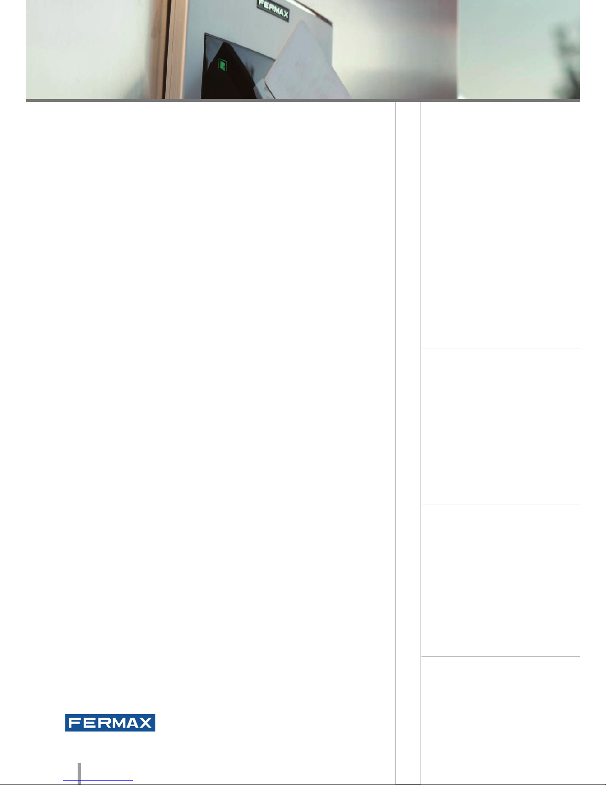
KEYPAD. The user should enter a code on the keypad. It is the
most economical model as it does not use identifiers. The same
code can be used by various users.
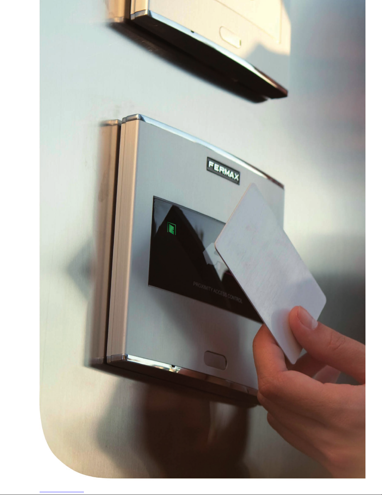
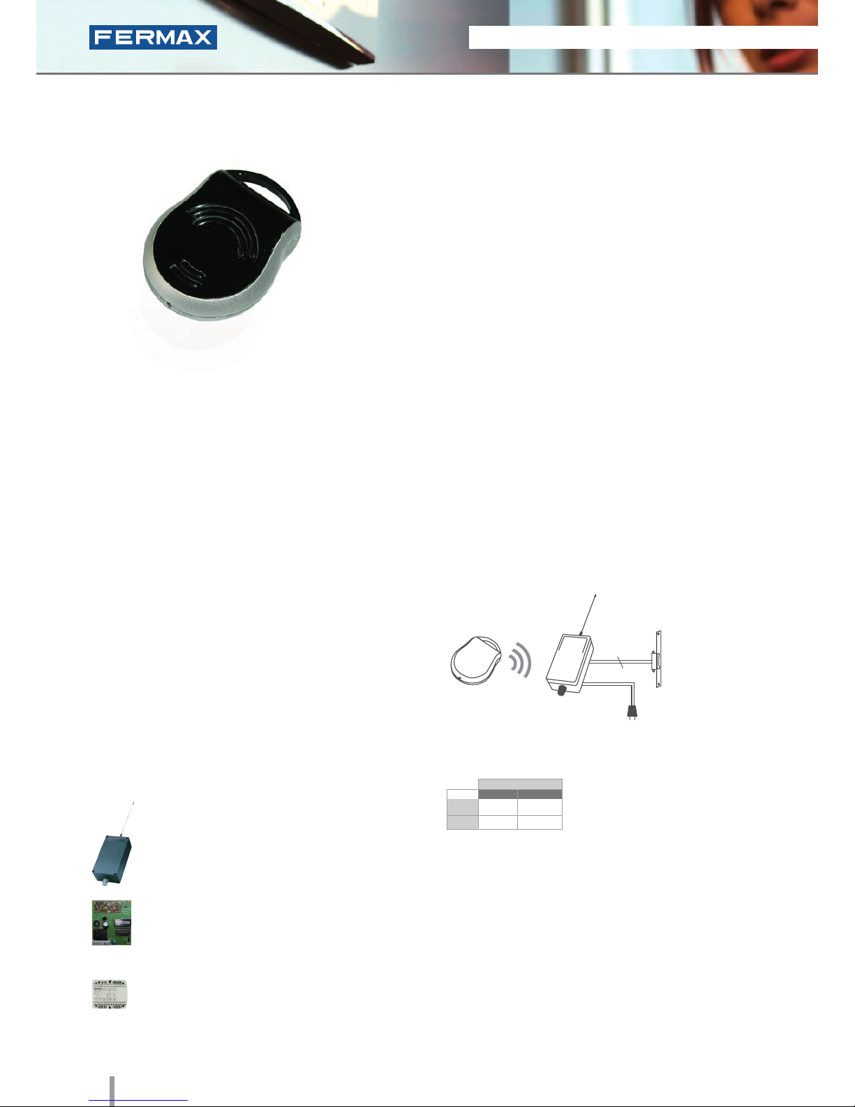
PROXIMITY. The identifier is a card (similar to a credit card)
or a proximity keyring. The identifier is swiped by the reader at
a distance of several centimetres. The reading is facilitated by
means of radio frequency data transmission.
BLUETOOTH. Access control functions by using mobile phones
with Bluetooth technology. The telephone system itself identifies
the user. The advantage of this system is the reader's operating
distance, which makes it very useful for vehicle and pedestrian
access.
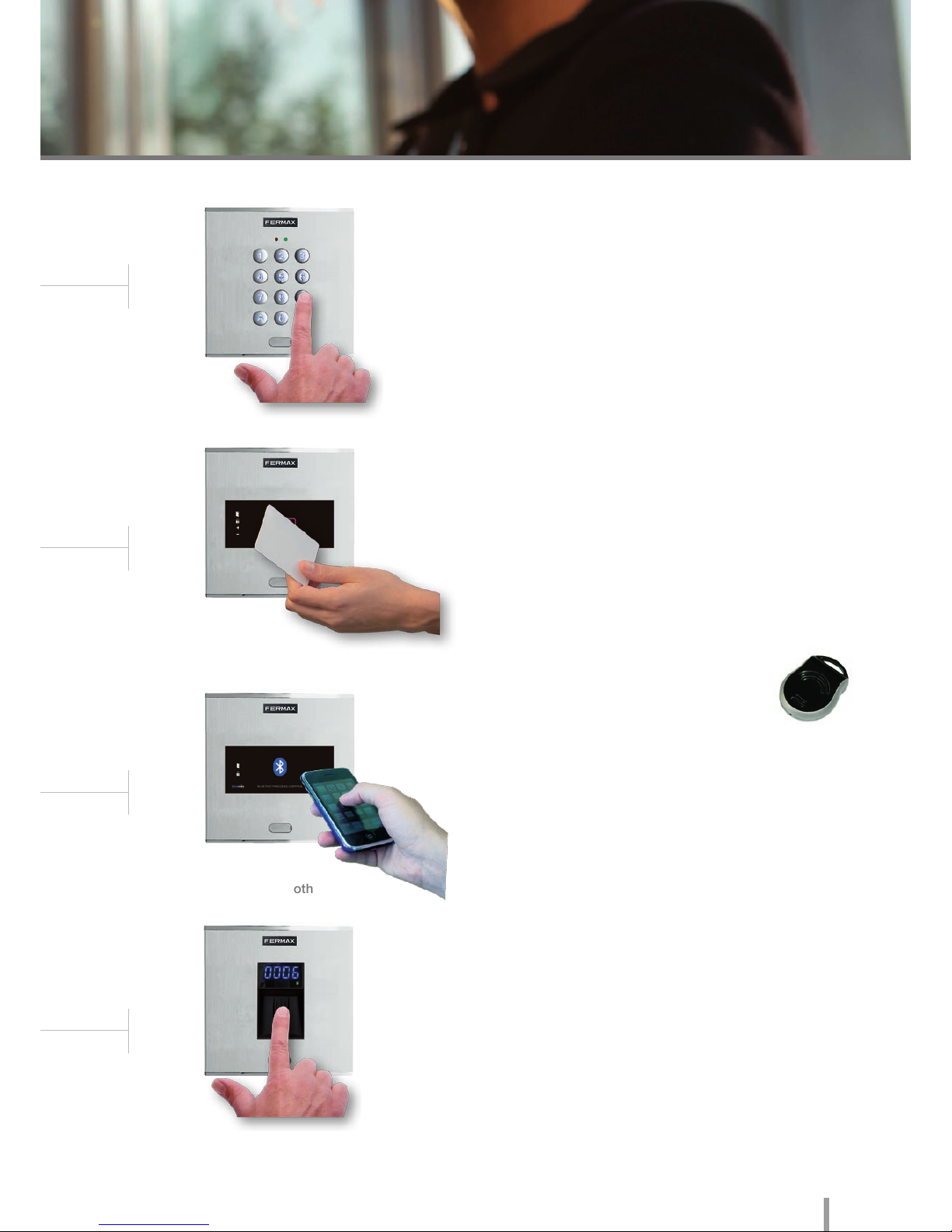
BIOMETRIC FINGERPRINT. Biometric fingerprint access
reader with sensor. Identifies the user by their fingerprint (feature
which is unrepeatable and unique to each person), offering a
greater level of security than any other system using another
type of identifier.
RADIO FREQUENCY. This technology
is mainly used in garage accesses given
the flexibility allowed by the large distance
between the identifier (control) and the receiver.
There are several types of technology, depending on the
interaction between the identifier and the reader.
Keypad
Proximity Reader
Bluetooth
Fingerprint
Page 10
8 2011 ACCESS CONTROL
2011 ACCESS CONTROL 9
• Dimensions:
* Reader
* Flush Mounted Box
* Surface Box
• Environmental Protection (IP)
• Anti-Shock Protection (IK)
• Power Supply (V)
• Consumption (mA) s/lock-release
• Operating Temperature
130x128
115x114x45
130x128x33
54
07
12V (ac/dc)
40/110
-15º to 55º C
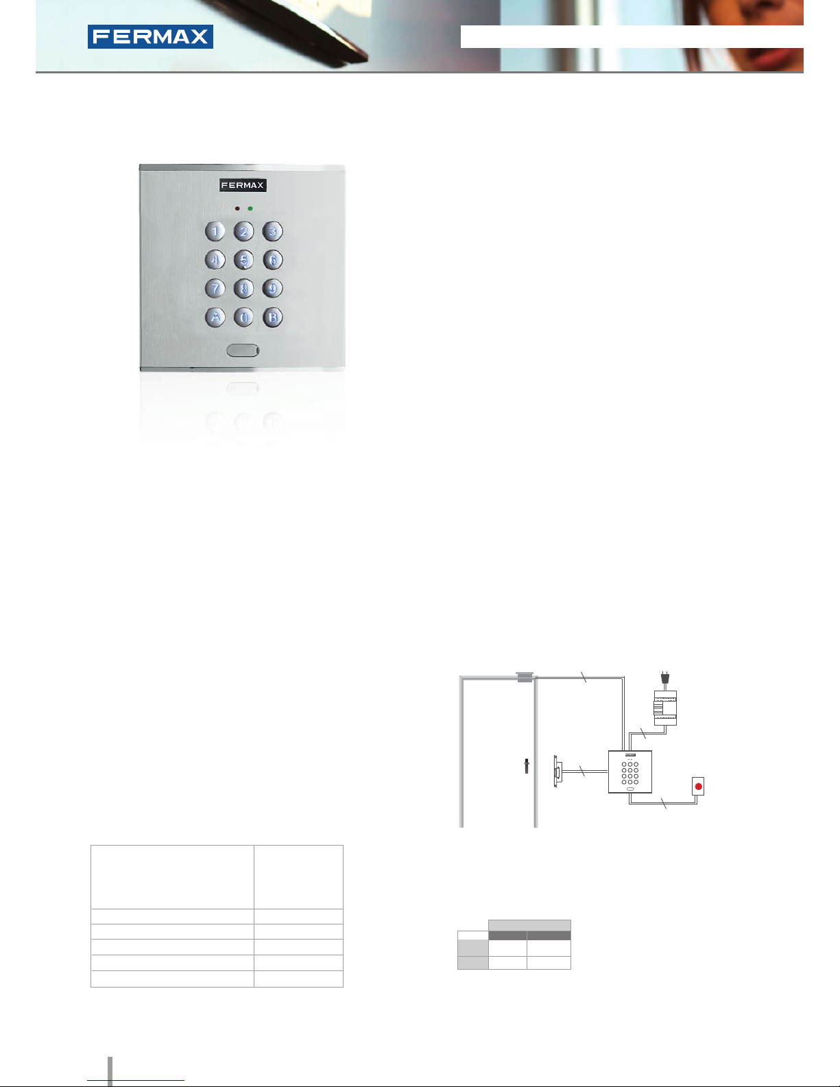
Ref.6991
Cityline Memokey
Keypad
• Access control keypad which allows the door to be
opened when a pre-programmed code of up to 6 digits
is entered.
• Capacity: up to 100 user codes.
• Length 4 to 6 digits.
• Integrated within the Cityline aluminum panel.
• Flush mounted (ref.8948, including box) or surface
installation (ref.7061, optional).
• Recommended for interiors and exteriors.
• Reader and controller integrated within the same module.
• Acoustic confirmation tone which sounds when a
button is pressed. Acoustic and visual confirmation
with LEDs showing if a code has been accepted/rejected.
• Blue backlit zamak keypad with status LED.
TECHNICAL FEATURES
INSTALLATION
PROGRAMMING
• 2A relay lock-release activation (NA, NC).
Programmable between 1 and 99 secs or bistable.
• Exit button input.
• Free access button input (trades).
• Auxiliary Open Collector Output (150mA max) to
indicate a vandalism attempt or open/forced door.
• Each code can activate 2 relays at the same time.
The keypad is located in the exterior area. The rest of the
devices are connected to this module and installed in the
building's interior: power supply and lock-release. An exit
button can be used optionally.
Programming from the same keypad using
a master code.
SPECIFICATIONS
Dimensions: (horizontal)x(vertical)x(depth) mm
Lock-Releases
Exit Button
Power Supply
Ref.6991
230Vac
2
2
2
2
STAND-ALONE
12Vdc
12Vac
30708
3071
2888
2880
* Door lock recommended.
Normal
References
Reinforced
Page 11

2011 ACCESS CONTROL 9
2011 ACCESS CONTROL 9
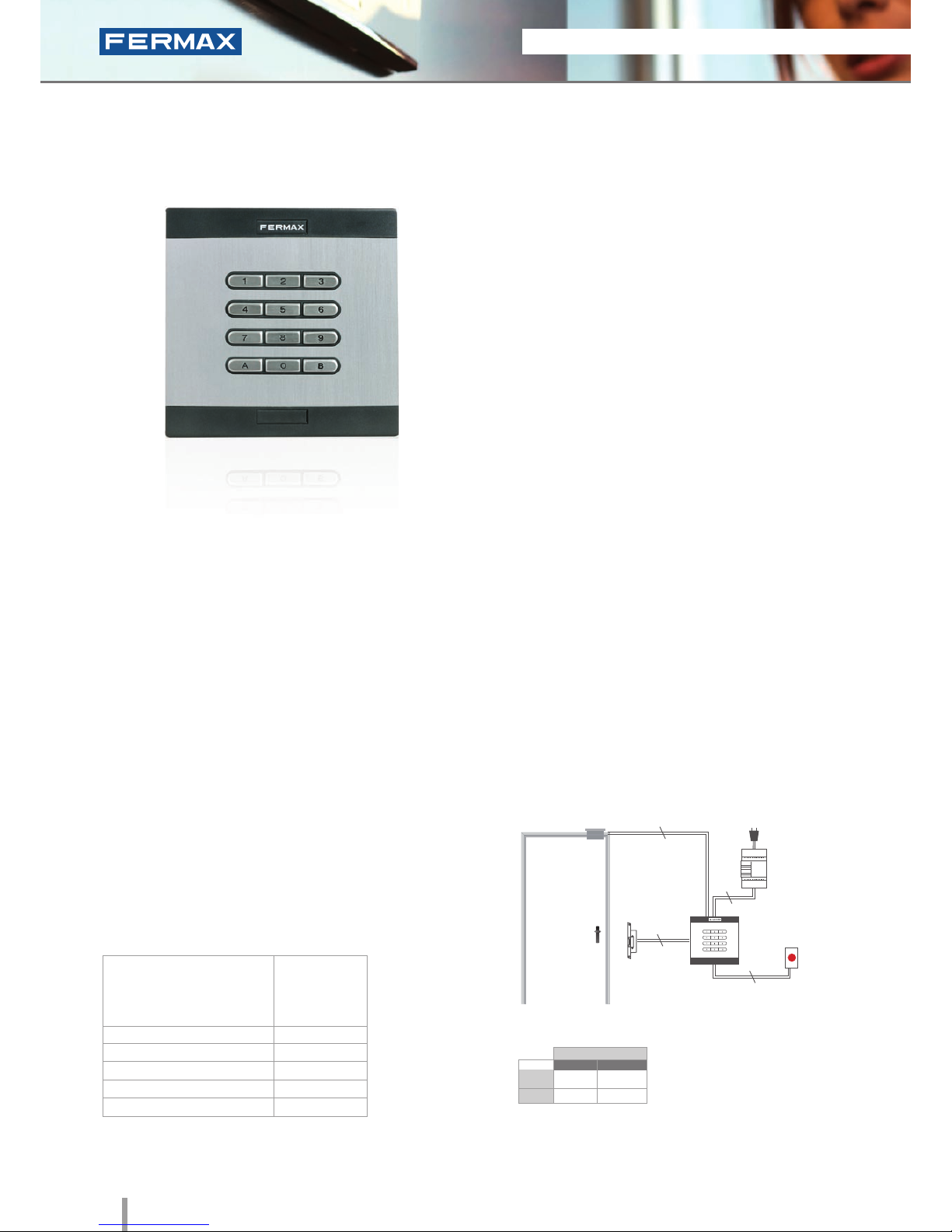
W Skyline Memokey
Ref.7438
Keypad
• Access control keypad module to be installed on
Skyline audio/video door entry system panels.
• Lock release on entering a code with up to 6 pre-
programmed digits.
• Capacity: up to 100 user codes.
• Length 4 to 6 digits.
• Blue backlit zamak keypad with status LEDs.
• Recommended for interior and exterior use.
• Reader and controller integrated within the same module.
• Acoustic confirmation tone which sounds when a
button is pressed. Acoustic and visual confirmation
with LEDs showing if a code has been accepted/
rejected.
TECHNICAL FEATURES
INSTALLATION
PROGRAMMING
• 2A relay lock-release activation (NA, NC).
Programmable from 1 and 99 seconds or bistable.
• Exit button input.
• Free access button input (trades).
• Auxiliary Open Collector Output (150mA max) to
indicate a vandalism attempt or open/forced door.
• Each code can activate 2 relays at the same time.
The electronic or video door entry system panels are located
in the building's exterior. The panel can be configured in
an intuitive manner using the memokey module for greater
ease of use and access security. The rest of the devices
are connected to this module and installed in the building's
interior: power supply and lock-release. An exit button can
be used optionally.
Programming from the same keypad using
a master code.
SPECIFICATIONS
Dimensions: (horizontal)x(vertical)x(depth) mm
• Reader Dimensions
• Environmental Protection (IP)
* Anti-Shock Protection (IK)
• Power Supply (V)
• Consumption (mA) s/lock-release
• Operating Temperature
105,2x95
54
07
12V (ac/dc)
40/110
-15º to 55º C
2
Lock-Releases
Exit Button
Power Supply
Ref. 7438
230Vac
2
2
2
STAND-ALONE
12Vdc
12Vac
30708
3071
2888
2880
* Door lock recommended.
Normal
References
Reinforced
Page 12
10 2011 ACCESS CONTROL
2011 ACCESS CONTROL 11
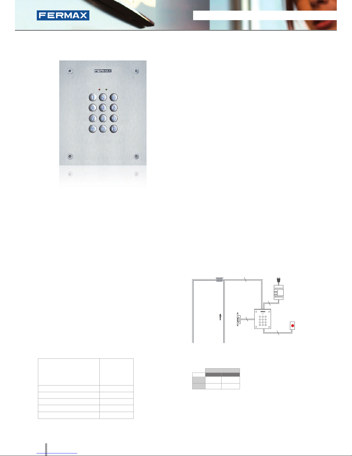
City Classic
Memokey
Ref.3610
Keypad
• Access control keypad which allows the door to be
opened when a pre-programmed code of up to 6 digits
is entered.
• Capacity: up to 100 user codes.
• Length 4 to 6 digits.
• Integrated within an aluminum City Classic panel.
• Flush mounted (ref.8948, including box) or surface
installation (ref.8951, optional).
• Recommended for interior and exterior use.
• Reader and controller integrated within the same module.
• Confirmation tone when a button is pressed or to
indicate that the code entered has been accepted/
rejected.
TECHNICAL FEATURES
INSTALLATION
PROGRAMMING
• 2A relay lock-release activation (NA, NC).
Programmable at from 1 and 99 seconds or bistable.
• Exit button input.
• Free access button input (trades).
• Auxiliary Open Collector Output (150mA max) to
indicate a vandalism attempt or open/forced door.
• Each code can activate 2 relays at the same time.
The keypad is located in the exterior area. The rest of the
devices are connected to this module and installed in the
building's interior: power supply and lock-release. An exit
button can be used optionally.
Programming from the same keypad using
a master code.
SPECIFICATIONS
Dimensions: (horizontal)x(vertical)x(depth) mm
• Dimensions:
* Reader
* Flush Mounted Box
* Surface Box
• Environmental Protection (IP)
* Anti-Shock Protection (IK)
• Power Supply (V)
• Consumption (mA) s/lock-release
• Operating Temperature
130x128
115x114x45
130x128x33
43
07
12V (ac/dc)
6/60
0º to 70º C
Lock-Releases
Exit Button
Power Supply
Ref.3610
230Vac
2
2
2
2
STAND-ALONE
12Vdc
12Vac
30708
3071
2888
2880
* Door lock recommended.
Normal
References
Reinforced
Page 13

2011 ACCESS CONTROL 11
2011 ACCESS CONTROL 11
City Classic CR
Memokey
Ref.3620 + Ref.3621
Keypad
• Access control keypad which allows the door to be opened
when a pre-programmed code of up to 6 digits is entered.
• Capacity for up to 100 user codes.
• Length 4 to 6 digits.
• Confirmation tone sounds when a button is pressed and to
indicate if the code entered has been accepted/rejected.
• Reader (ref.3620) and controller (ref.3621) in two
independent modules.
• The controller is installed in the building's interior near the
power supply and lock-release.
• The metallic box is included with the controller.
• Flush mounted (ref.8948, including box) or surface
installation (ref.8951, optional).
• A second keypad CR can be added in the building's
interior.
• Maximum distance between reader and controller of 100m.
• Reader and controller not integrated within the same
module.
TECHNICAL FEATURES
INSTALLATION
PROGRAMMING
• 2A relay lock-release activation (NA, NC).
Programmable at from 1 and 99 seconds or bistable.
• Exit button input.
• Free access button input (trades).
• Auxiliary Open Collector Output (150mA max) to
indicate a vandalism attempt or open/forced door.
• Each code can activate 2 relays at the same time.
The CR keypad is located in the exterior of the building and
is connected to the controller in the interior in the same way
as the rest of the device (power supply and lock-release).
An exit button can be used optionally.
Programming from the same keypad using
a master code.
SPECIFICATIONS
Dimensions: (horizontal)x(vertical)x(depth) mm
• Dimensions:
* Reader
* Flush Mounted Box
* Surface Box
* Metallic Box
• Environmental Protection (IP)
* Anti-Shock Protection (IK)
• Power Supply (V)
• Consumption (mA) s/lock-release
• Operating Temperature
130x128
115x114x45
130x128x33
154x203x50
43
07
12V (ac/dc)
6/60
0º to 70º C
Lock-Releases
Exit Button
Power Supply
Ref.3621
Ref.3620
230Vac
2
2
6
STAND-ALONE
12Vdc
12Vac
30708
3071
2888
2880
* Door lock recommended.
Normal
References
Reinforced
Page 14
12 2011 ACCESS CONTROL
2011 ACCESS CONTROL 13
Marine Memokey
Ref.4699
Keypad
• Access control keypad which allows the door to be
opened when a pre-programmed code of up to 6
digits is entered.
• Capacity: up to 100 user codes.
• Length 4 to 6 digits.
• Integrated within a 2.5mm stainless steel Marine panel.
• Flush mounted (ref.4641, including
box) or surface installation (ref.4701, optional).
• Recommended for interior and exterior use.
• Reader and controller integrated within the same module.
• Acoustic confirmation tone which sounds when a
button is pressed. Acoustic and visual confirmation
with LED’s showing if a code has been accepted/
rejected.
• Blue backlit zamak keypad with status LEDs.
TECHNICAL FEATURES INSTALLATION
PROGRAMMING
• 2A relay lock-release activation (NA, NC).
Programmable at from 1 and 99 seconds or bistable.
• Exit button input.
• Free access button input (trades).
• Auxiliary Open Collector Output (max. 150mA) to
indicate a vandalism attempt or open/forced door.
• Each code can activate 2 relays at the same time.
The keypad is located in the exterior area. The rest of the
devices are connected to this module and installed in the
building's interior: power supply and lock-release. An exit
button can be used optionally.
Programming from the same keypad using
a master code.
SPECIFICATIONS
Dimensions: (horizontal)x(vertical)x(depth) mm
• Dimensions:
* Reader
* Flush Mounted Box
* Surface Box
• Environmental Protection (IP)
• Anti-Shock Protection (IK)
• Power Supply (V)
• Consumption (mA) S/lock-release.
• Operating Temperature
150x180
130x160x55
154x184x55
54
09
12V (ac/dc)
40/110
-15º to 55º C
Lock-Releases
Exit Button
Power Supply
Ref.4699
230Vac
2
2
2
2
STAND-ALONE
12Vdc
12Vac
30708
3071
2888
2880
* Door lock recommended.
Normal
References
Reinforced
Page 15
2011 ACCESS CONTROL 13
2011 ACCESS CONTROL 13
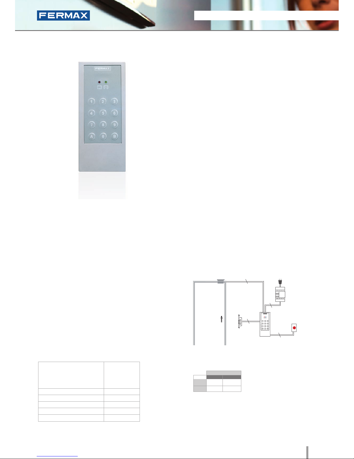
Loft Memokey
Ref.4540
Keypad
• Access control keypad which allows the door to be
opened when a pre-programmed code of up to 6
digits is entered.
• Membrane keypad finished in texturised ABS plastic
with status LEDs.
• Surface installation.
• Capacity: up to 100 user codes.
• Length 4 to 6 digits.
• Recommended for interior use.
• Includes 50cm of wiring.
• Reader and controller integrated within the same module.
• Acoustic confirmation tone which sounds when a
button is pressed. Acoustic and visual confirmation
with LED’s showing if a code has been accepted/
rejected.
TECHNICAL FEATURES INSTALLATION
PROGRAMMING
• 2A relay lock-release activation (NA, NC).
Programmable at from 1 and 99 seconds or
bistable.
• Exit button input.
• Free access button input (trades).
• Auxiliary Open Collector Output (max. 150 mA) to
indicate a vandalism attempt or open/forced door.
• Tamper proof to indicate vandalism attempts.
The keypad is located in the exterior area. The rest of
the devices are connected to this module and they are
installed in the building's interior: power supply and lock-
release. An exit button can be used optionally.
Programming from the same keypad using
a master code.
SPECIFICATIONS
Dimensions: (horizontal)x(vertical)x(depth) mm
• Dimensions:
* Reader
* Flush Mounted Box
* Surface Box
• Environmental Protection (IP)
• Anti-Shock Protection (IK)
• Power Supply (V)
• Consumption (mA) s/lock-release.
• Operating Temperature
60x130x23
Not required
Not required
66
06
12V (ac/dc)
20/70
0º to 70º C
Lock-Releases
Exit Button
Power Supply
Ref.4540
230Vac
2
2
2
2
STAND-ALONE
12Vdc
12Vac
30708
3071
2888
2880
* Door lock recommended.
Normal
References
Reinforced
Page 16
14 2011 ACCESS CONTROL
2011 ACCESS CONTROL 15
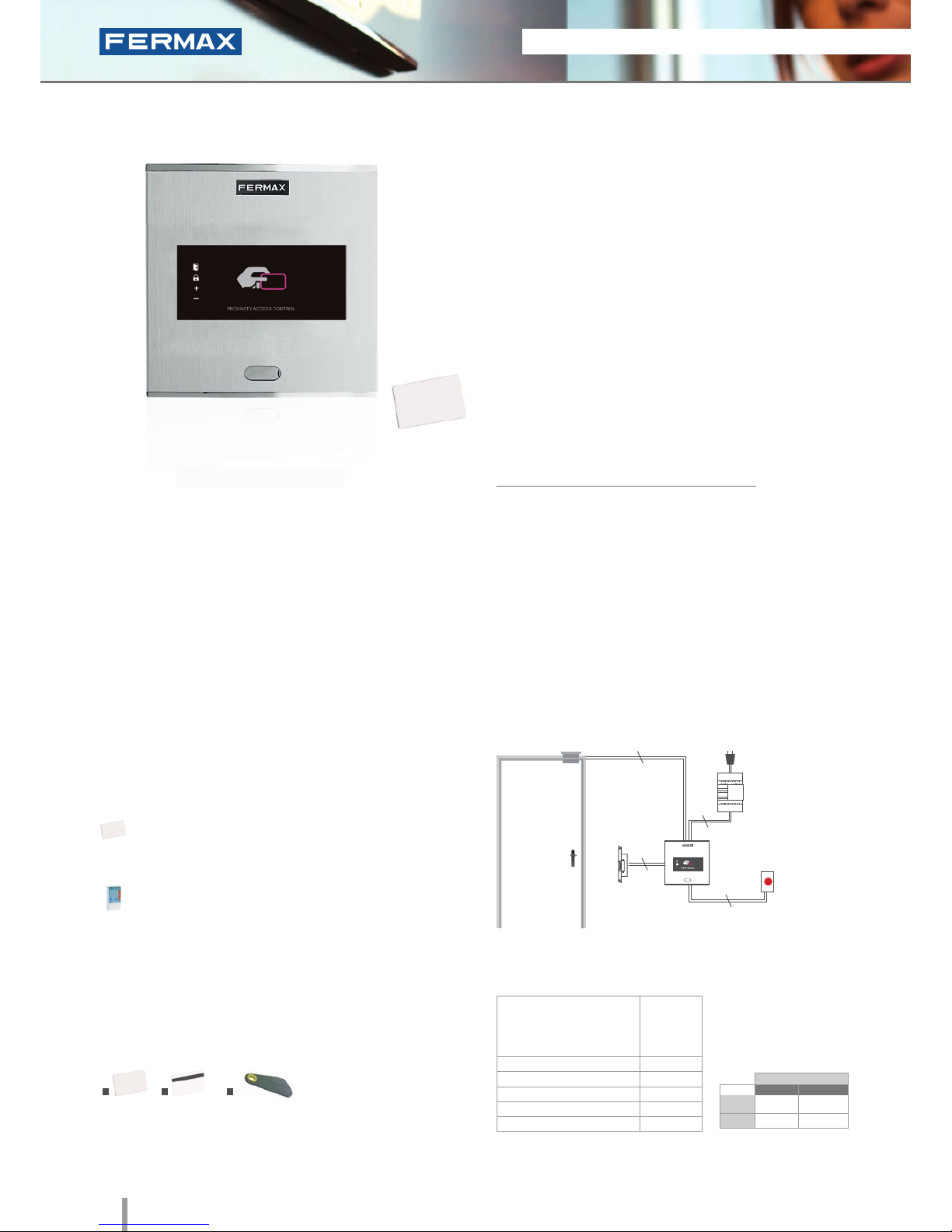
Cityline Private
Ref.6992
Proximity
• Access control reader which allows the door to be opened
by swiping the proximity card or keyring. Only authorised
cards or keyrings activate the device. Physical contact is not
necessary.
• Integrated within the Cityline aluminum panel.
• Flush mounted (ref.8948, including box) or surface
installation (ref.7061, optional).
• Recommended for interior and exterior use.
• Reader and controller integrated within the same module.
• Can operate as a stand-alone or centralised system.
Congurable between dipswitches (SW2).
Configuration as a STAND-ALONE system:
• Capacity: up to 400 user cards or keyrings.
• Acoustic and visual confirmation using LEDs which
advise if the card swiped has been accepted/rejected.
Dimensions: (horizontal)x(vertical)x(depth) mm
INSTALLATION
SPECIFICATIONS
• Dimensions:
* Reader
* Flush Mounted Box
* Surface Box
• Environmental Protection (IP)
• Anti-Shock Protection (IK)
• Power Supply (V)
• Consumption (mA) S/lock-release
• Operating Temperature
130x128
115x114x45
130x128x33
54
07
12V (ac/dc)
90
-15º to 55ºC
TECHNICAL FEATURES
• Does not require physical contact.
5cm (card) or 1.5cm (keyring) reading distance.
• Acoustic and visual status data.
• Status LEDs (help in programming and determining
status).
• Manual programming (using master card or keyring)
or via PC software (card activation/deactivation).
• Door sensor and exit button control.
• Relay output.
• Relay lock-release activation with programmable
time. Programmable from 1 to 99 seconds.
IDENTIFIERS
1. Card without magnetic strip (ref.23361); 2. Card with magnetic strip
(ref.2336); 3. Proximity keyring (ref.44501).
The reader is located in the exterior area. The rest of the
devices are connected to this module and they are installed in
the building's interior: power supply and lock-release. An exit
button can be used optionally.
Lock-Releases
Exit Button
Power Supply
Ref.6992
230Vac
2
2
2
2
PROGRAMMING
This can be done in 3 ways:
Master card: The first time the power supply is
connected, the system waits for a proximity card to be
swiped. This is then considered the "master card".
Keypad: Recommended if we want to deactivate
faulty cards.
PC Software: For managing user activation/
deactivations.
The WINPROX software can be downloaded from
www.fermax.com
1 2
3
STAND-ALONE
12Vdc
12Vac
30708
3071
2888
2880
* Door lock recommended.
Normal
References
Reinforced
Page 17
2011 ACCESS CONTROL 15
2011 ACCESS CONTROL 15
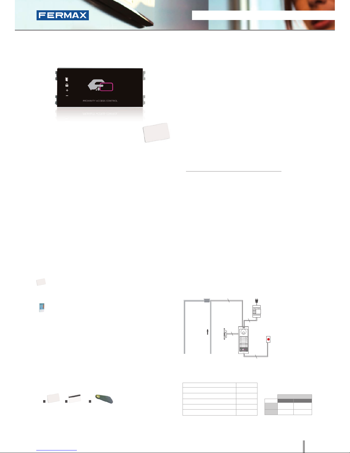
• Access control reader which allows the door to be opened
by swiping the proximity card or keyring. Only authorised
cards or keyrings activate the device. Physical contact is
not necessary.
• Access control module to be integrated within Skyline
audio/video door entry system panels.
• Recommended for interior and exterior use.
• Reader and controller integrated within the same module.
• Can operate as a stand-alone or centralised system.
Congurable between dipswitches (SW2).
Configuration as a STAND-ALONE system:
• Capacity: up to 400 user cards or keyrings.
• Acoustic and visual confirmation using LEDs which
advise if the card swiped has been accepted/ rejected.
INSTALLATION
The electronic or video door entry system panels are located
in the building's exterior. The panel can be configured in an
intuitive manner using the private module for greater ease of
use and access security. The rest of the devices are connected
to this module and they are installed in the building's interior:
power supply and lock-release. An exit button can be used
optionally.
V Skyline Private
Ref.7440
Proximity
TECHNICAL FEATURES
• Does not require physical contact.
5cm (card) or 1.5cm (keyring) reading distance.
• Acoustic and visual status data.
• Status LEDs (help in programming and determining
status).
• Manual programming (using master card or keyring)
or via PC software (card activation/deactivation).
• Door sensor and exit button control.
• Relay output.
• Relay lock-release activation with programmable
time. Programmable at 1 to 99 secs.
Lock-Releases
Exit Button
Power Supply
Ref.7440
230Vac
2
2
2
2
SPECIFICATIONS
• Reader Dimensions:
• Environmental Protection (IP)
• Anti-Shock Protection (IK)
• Power Supply (V)
• Consumption (mA) S/lock-release
• Operating Temperature
105.2X47.5
54
07
12V (ac/dc)
90
-15º to 55ºC
PROGRAMMING
This can be done in 3 ways:
Master card: The first time the power supply is
connected, the system waits for a proximity card to be
swiped. This is then considered the "master card".
Keypad: Recommended if we want to deactivate
faulty cards.
PC Software: For managing user activation/
deactivations.
The WINPROX software can be downloaded from
www.fermax.com
IDENTIFIERS
1. Card without magnetic strip (ref.23361); 2. Card with magnetic strip
(ref.2336); 3. Proximity keyring (ref.44501).
Dimensions: (horizontal)x(vertical)x(depth) mm
1 2
3
STAND-ALONE
12Vdc
12Vac
30708
3071
2888
2880
* Door lock recommended.
Normal
References
Reinforced
Page 18

16 2011 ACCESS CONTROL
2011 ACCESS CONTROL 17
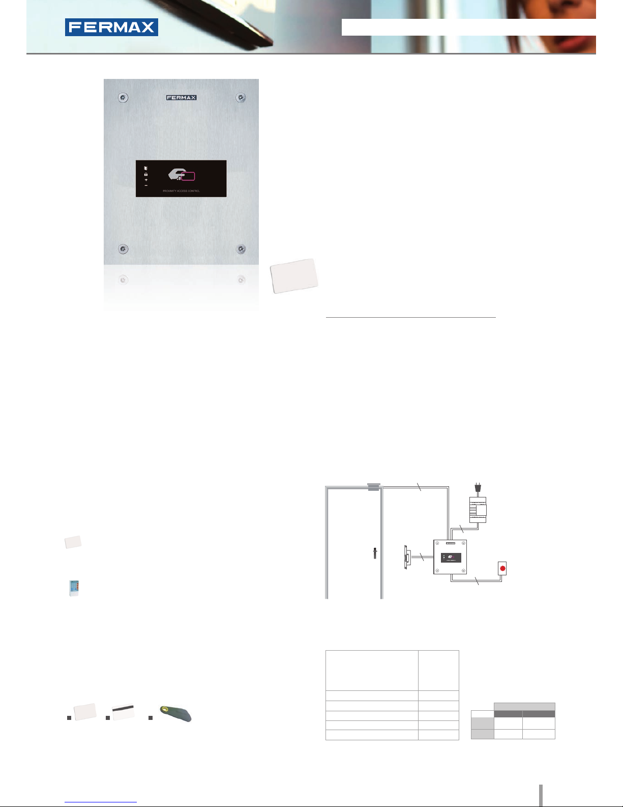
City Classic Private
Ref.2347
Proximity
• Access control reader which allows the door to be opened
by swiping the proximity card or keyring . Only authorised
cards or keyrings activate the device. Physical contact is
not necessary.
• Capacity: up to 400 user cards or keyrings.
• Integrated within the City Classic aluminum panel.
• Flush mounted (ref.8948, including box) or surface
installation (ref.8951, optional).
• Recommended for interior and exterior use.
• Reader and controller integrated within the same module.
• Acoustic and visual confirmation using LEDs which
advise if the card presented has been accepted/rejected.
Dimensions: (horizontal)x(vertical)x(depth) mm
INSTALLATION
TECHNICAL FEATURES
• Does not require physical contact.
3cm (card) or 1cm (keyring) reading distance.
• Acoustic and visual status data.
• Manual programming (using master card or keyring)
or via PC software (card activation/deactivation).
• Door sensor and exit button control.
• Relay output.
• Relay lock-release activation with programmable time.
Programmable from 1 to 99 seconds.
• Status LEDs (help in programming and determining
status).
SPECIFICATIONS
• Dimensions:
* Reader
* Flush Mounted Box
* Surface Box
• Environmental Protection (IP)
• Anti-Shock Protection (IK)
• Power Supply (V)
• Consumption (mA) S/lock-release
• Operating Temperature
130x128
115x114x45
130x128x33
43
07
12V (ac/dc)
80/120
0º to 60ºC
The reader is located in the exterior area. The rest of the
devices are connected to this module and they are installed in
the building's interior: power supply and lock-release. An exit
button can be used optionally.
Lock-Releases
Exit Button
Power Supply
Ref.2347
230Vac
2
2
2
2
PROGRAMMING
This can be done in 3 ways:
Master card: The first time the power supply is
connected, the system waits for a proximity card to be
swiped. This is then considered the "master card".
Keypad: Recommended if we want to deactivate
faulty cards.
PC Software: For managing user activation/
deactivations.
The WINPROX software can be downloaded from
www.fermax.com
IDENTIFIERS
1. Card without magnetic strip (ref.23361); 2. Card with magnetic strip
(ref.2336); 3. Proximity keyring (ref.44501).
1 2
3
STAND-ALONE
12Vdc
12Vac
30708
3071
2888
2880
* Door lock recommended.
Normal
References
Reinforced
Page 19
2011 ACCESS CONTROL 17
2011 ACCESS CONTROL 17
• Access control reader which allows the door to be opened
by swiping the proximity card or keyring. Only authorised
cards or keyrings activate the device. Physical contact is
not necessary.
• Integrated within a 2.5mm Marine stainless steel panel.
• Flush mounted (ref.4641, including box) or surface
installation (ref.4701, optional).
• Recommended for interior and exterior use.
• Reader and controller integrated within the same module.
• Can operate as a stand-alone or centralised system.
Congurable between dipswitches (SW2).
Configuration as a STAND-ALONE system:
• Capacity: up to 400 user cards or keyrings.
• Acoustic and visual confirmation using status LEDs
which advise if the card swiped has been accepted/
rejected.
INSTALLATION
The reader is located in the exterior area. The rest of the devices
are connected to this module and installed in the building's
interior: power supply and lock-release. An exit button can be
used optionally.
SPECIFICATIONS
Marine Private
Ref.5472
Proximity
TECHNICAL FEATURES
• Does not require physical contact.
4cm (card) or 1cm (keyring) reading distance.
• Acoustic and visual status data.
• Manual programming (using master card or keyring)
or via PC software (card activation/deactivation).
• Door sensor and exit button control.
• Relay output.
• Relay lock-release activation with programmable
time. Programmable from 1 to 99 seconds.
• Status LEDs (help in programming and determining
status).
• Dimensions:
* Reader
* Flush Mounted Box
* Surface Box
• Environmental Protection (IP)
• Anti-Shock Protection (IK)
• Power Supply (V)
• Consumption (mA) S/lock-release
• Operating Temperature
150x180
130x160x55
154x184x55
54
09
12V (ac/dc)
90
-15º to 55ºC
Lock-Releases
Exit Button
Power Supply
Ref.5472
230Vac
2
2
2
2
PROGRAMMING
This can be done in 3 ways:
Master card: The first time the power supply is
connected, the system waits for a proximity card to be
swiped. This is then considered the "master card".
Keypad: Recommended if we want to deactivate
faulty cards.
PC Software: For managing user activations/
deactivations.
The WINPROX software can be downloaded from
www.fermax.com.
IDENTIFIERS
1. Card without magnetic strip (ref.23361); 2. Card with magnetic strip
(ref.2336); 3. Proximity keyring (ref.44501).
Dimensions: (horizontal)x(vertical)x(depth) mm
1 2
3
STAND-ALONE
12Vdc
12Vac
30708
3071
2888
2880
* Door lock recommended.
Normal
References
Reinforced
Page 20
18 2011 ACCESS CONTROL
2011 ACCESS CONTROL 19
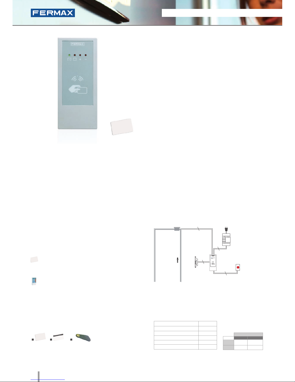
Loft Private
Ref.4530
Proximity
• Access control reader which allows the door to be opened
by swiping the proximity card or keyring. Only authorised
cards or keyrings activate the device. Physical contact is
not necessary.
• Capacity: up to 400 user cards or keyrings.
• Module finished in textured ABS plastic.
• Surface installation.
• Recommended for interior use.
• Includes 50 cm of wiring.
• Reader and controller integrated within the same module.
• Acoustic and visual confirmation using LEDs which
advise if the card swiped has been accepted/rejected.
Dimensions: (horizontal)x(vertical)x(depth) mm
INSTALLATION
The reader is located in the exterior area. The rest of the
devices are connected to this module and they are installed in
the building's interior: power supply and lock-release. An exit
button can be used optionally.
TECHNICAL FEATURES
• Does not require physical contact.
4 cm (card) or 1 cm (keyring) reading distance.
• Acoustic and visual status data.
• Manual programming (using master card or keyring)
or via PC software (card activation/deactivation).
• Door sensor and exit button control.
• Relay output.
• Relay lock-release activation with programmable
time. Programmable from 1 to 99 seconds.
• Status LED (help in programming and determining
status).
SPECIFICATIONS
• Reader Dimensions
• Environmental Protection (IP)
• Anti-Shock Protection (IK)
• Power Supply (V)
• Consumption (mA) S/lock-release
• Operating Temperature
60x130x23
66
06
12V (ac/dc)
45/75
0º to 60ºC
Lock-Releases
Exit Button
Power Supply
Ref.2347
230Vac
2
2
2
2
PROGRAMMING
This can be done in 3 ways:
Master card: The first time the power supply is
connected, the system waits for a proximity card to be
swiped. This is then considered the "master card".
Keypad: Recommended if we want to deactivate
faulty cards.
PC Software: For managing user activation/
deactivations. The WINPROX software can be
downloaded from www.fermax.com
STAND-ALONE
IDENTIFIERS
1. Card without magnetic strip (ref.23361); 2. Card with magnetic strip
(ref.2336); 3. Proximity keyring (ref.44501).
1 2
3
12Vdc
12Vac
30708
3071
2888
2880
* Door lock recommended.
Normal
References
Reinforced
Page 21

2011 ACCESS CONTROL 19
2011 ACCESS CONTROL 19
Identifiers
Maintenance
Credit Card Format white PVC material.
Each device comes with an identier to allow
it to setup in the system. It does not require
maintenance or batteries.
ASK 125KHz Modulation. Code Protocol.
Allows it to be personalized with the users
logo and photograph using various printing
options. See prices and commercial
references.
Dimensions: 85x54mm.
Proximity Card without
magnetic strip
Proximity Card with
magnetic strip
Proximity Keyring
Ref.23361
Ref.2336
Ref.44501
Similar to the above, but also incorporates
a high coercivity magnetic strip for other
functions.
To carry the identifier along with traditional
keys. Each device comes with an identier
to allow it to be set up in the system (with
exclusive identifiers).
The proximity reader is used in residential
settings given its ease of use.
Reduced dimensions: 25x52mm.
For maintenance service and information
management in PRIVATE systems. Allows you to
receive and compile comprehensive information
on the READER's users.
It can be downloaded from www.fermax.com
WINPROX allows you to manage the access
control system's autonomous proximity readers,
their users and cards, manage incidents online,
control IP cameras, generate reports, etc in an
easy intuitive manner.
With WINPROX you can dene various access
readers, activate or deactivate users, assign
various cards to a single user, configure access
permission for various users on a single system,
manage card expiry, import and export user lists
to excel, etc.
PC Programming Software:
WINPROX
Recommended for maintenance work
and to manually deactivate the faulty card
from the reader itself.
Also allows you to carry out all
programming operations using simple
commands.
PC Programming Kit for Private Loft
readers.
Includes a PC and CD interface with
WINPROX software.
Programming Keypad
Private
Programming Kit
PC Loft
Ref.2306
Ref.3625
STAND-ALONE
Page 22
20 2011 ACCESS CONTROL
2011 ACCESS CONTROL 21
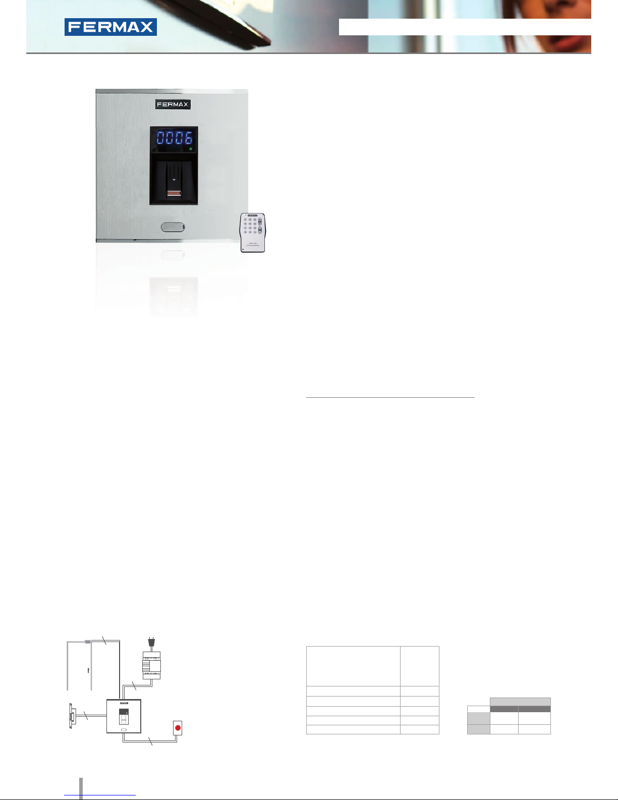
Cityline Fingerprint
Ref.6959
Fingerprint
• Biometric access fingerprint reader with capacitive sensor.
Identifies the user by way of their fingerprint (a unique,
unrepeatable characteristic). With built-in proximity reader
which functions as follows:
- Some people have fingerprints without the necessary
information for authorization in a biometric system. This applies
to 1% of the population. In these cases, use integrated
Proximity.
- Security mode: activates dual security, (Fingerprint+Card) for
the same User.
• Integrated within the Cityline aluminum panel.
• Flush mounted (ref.8948, including box) or surface
installation (ref.7061, optional).
• Recommended for interior and exterior use.
• Reader and controller integrated within the same module.
• Can run as an stand-alone or centralised system
(dipswitch configurable).
Configuration as a STAND-ALONE system:
• Capacity (no. users):
- 4.500 users in 1 fingerprint per person mode.
- 2.970 users in 2 fingerprints per person mode.
• Acoustic and visual confirmation using status and display
LEDs which indicate if a fingerprint has been accepted or
rejected.
• To ensure the ngerprint is read correctly, slide your nger along
the reader with a downwards movement (from top to bottom),
at a uniform speed and exerting slight pressure.
• Includes a software CD and infrared remote keypad.
PROGRAMMING
TECHNICAL FEATURES
• Relay lock-release activation. Programmable from
01 to 99 seconds.
• Acoustic and visual status data.
• Reader with 2 status LEDs and a 7 segment 4 digit
display (helps with programming and status data).
• Manual programming using the infrared remote
control included or via PC software (card activation/
deactivation of fingerprints).
• Special Functions: free ngerprint button (trades) and
unblock fingerprint (lock-release always activated).
• Door sensor and exit button control.
• Auxiliary Relay for other Functions. Door alarm and
forced door, panic alarm or intruder alarm (incorrect
fingerprint).
• Allows keypad connection for Security Mode
operation: in this case, the dual security would be
Fingerprint+Code, for the same User.
Programming can be done manually or by PC. The system
is programmed with a master print (Administrator) and a
remote infrared keypad. The PC programming software can be
downloaded from www.fermax.com. The «Clone» option is available:
it is used to copy all data entered in one reader into another.
NOTE: See
“Installation
diagrams for
stand-alone
in network
fingerprint
readers”.
Built-in Proximity reader
The fingerprint reader is located in the exterior area. The
rest of the devices are connected to this module and they
are installed in the building's interior: power supply and
lock-release. An exit button can be used optionally.
INSTALLATION
Dimensions: (horizontal)x(vertical)x(depth) mm
SPECIFICATIONS
• Dimensions:
* Reader
* Flush Mounted Box
* Surface Box
• Environmental Protection (IP)
• Anti-Shock Protection (IK)
• Power Supply (V)
• Consumption (mA) S/lock-release
• Operating Temperature
130x128
115x114x45
130x128x33
43
07
12V (ac/dc)
118/173
-10º to 55ºC
Lock-Releases
Exit Button
Power Supply
Ref.6959
230Vac
2
2
2
2
024
STAND-ALONE
* Door lock recommended.
12Vdc
12Vac
30708
3071
2888
2880
Normal
References
Reinforced
Page 23
2011 ACCESS CONTROL 21
2011 ACCESS CONTROL 21
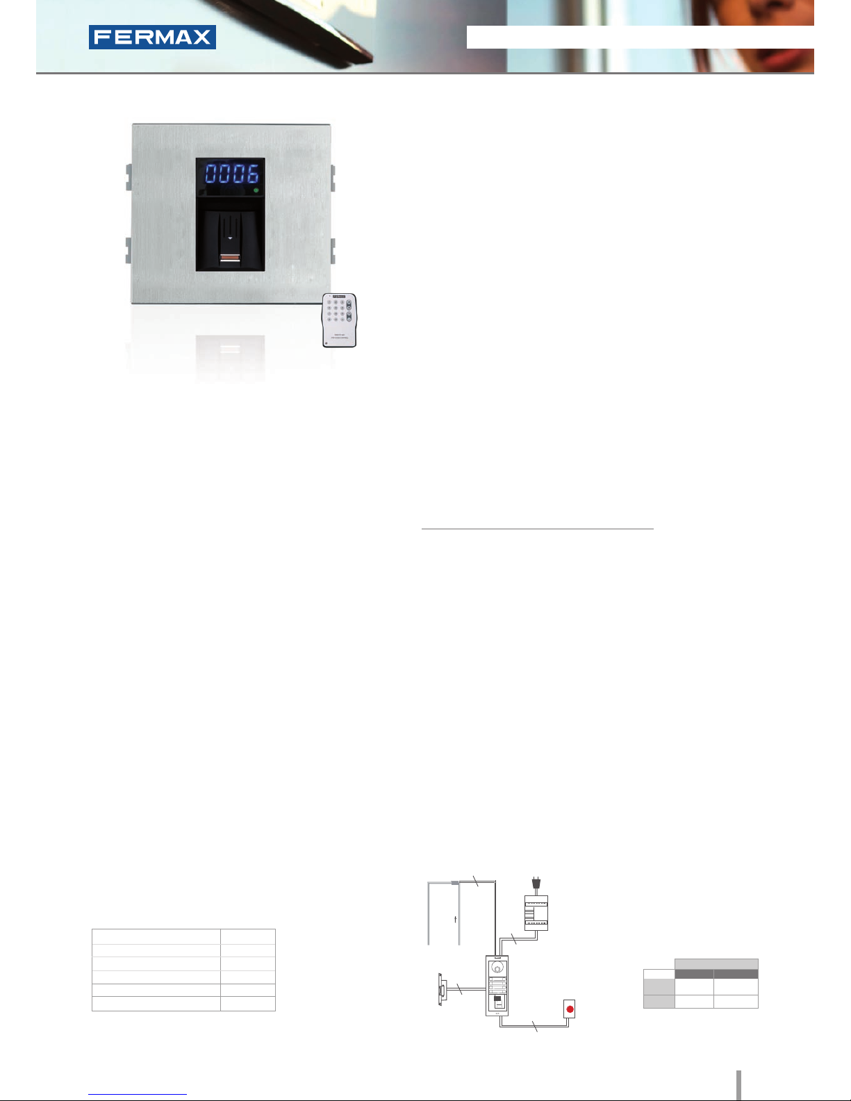
W Skyline Fingerprint
Ref.6989
Fingerprint
• Biometric access fingerprint reader with capacitive sensor.
Identifies the user by way of their fingerprint (a unique,
unrepeatable characteristic). With built-in proximity reader
which functions as follows:
- Some people have fingerprints without the necessary
information for authorization in a biometric system. This applies
to 1% of the population. In these cases, use integrated
Proximity.
- Security mode: activates dual security, (Fingerprint+Card) for
the same User.
• Access control module, to be integrated within Skyline
audio/video door-entry system panels.
• Recommended for interior and exterior use.
• Reader and controller integrated within the same module.
• Can operate as an stand-alone or centralised system
(dipswitch configurable).
Configuration as a STAND-ALONE system:
• Capacity (no. users):
- 4.500 users in 1 fingerprint per person mode.
- 2.970 users in 2 fingerprints per person mode.
• Acoustic and visual confirmation using status and
display LEDs which indicate if a fingerprint has been
accepted or rejected.
• To ensure the ngerprint is read correctly, slide your nger along
the reader with a downwards movement (from top to bottom),
at a uniform speed and exerting slight pressure.
• Includes a software CD and infrared remote keypad.
PROGRAMMING
TECHNICAL FEATURES
INSTALLATION
The electronic or video door-entry system panels are located in
the building's exterior. The panel can be configured in an intuitive
manner, including a fingerprint reader module for greater ease of
use and access security. The rest of the devices are connected to
this module and they are installed in the building's interior: power
supply and lock-release. An exit button can be used optionally.
Programming can be done manually or by PC. The system
is programmed with a master print (Administrator) and a
remote infrared keypad. The PC programming software
can be downloaded from www.fermax.com. The «Clone»
option is available: it is used to copy all data entered in
one reader into another.
• Relay lock-release activation Programmable from
01 to 99 seconds.
• Acoustic and visual status data.
• Reader with 2 status LEDs and a 7 segment 4 digit
display (helps with programming and status data).
• Manual programming using the infrared remote
control included or via PC software (card activation/
deactivation of fingerprints).
• Special Functions: free ngerprint button (trades) and
unblock fingerprint (lock-release always activated).
• Door sensor and exit button control.
• Auxiliary Relay for other Functions. Door alarm and
forced door, panic alarm or intruder alarm (incorrect
fingerprint).
• Allows keypad connection for Security Mode
operation: in this case, the dual security would be
Fingerprint+Code, for the same User.
Lock-Releases
Exit Button
Power Supply
Ref.6989
230Vac
2
2
2
2
024
Dimensions: (horizontal)x(vertical)x(depth) mm
SPECIFICATIONS
• Dimensions:
• Environmental Protection (IP)
• Anti-Shock Protection (IK)
• Power Supply (V)
• Consumption (mA) s/lock-release
• Operating Temperature
105.2x95
43
07
12V (ac/dc)
118/173
-10º to 55ºC
Built-in Proximity reader
STAND-ALONE
12Vdc
12Vac
30708
3071
2888
2880
* Door lock recommended.
Normal
References
Reinforced
Page 24
22 2011 ACCESS CONTROL
2011 ACCESS CONTROL 23
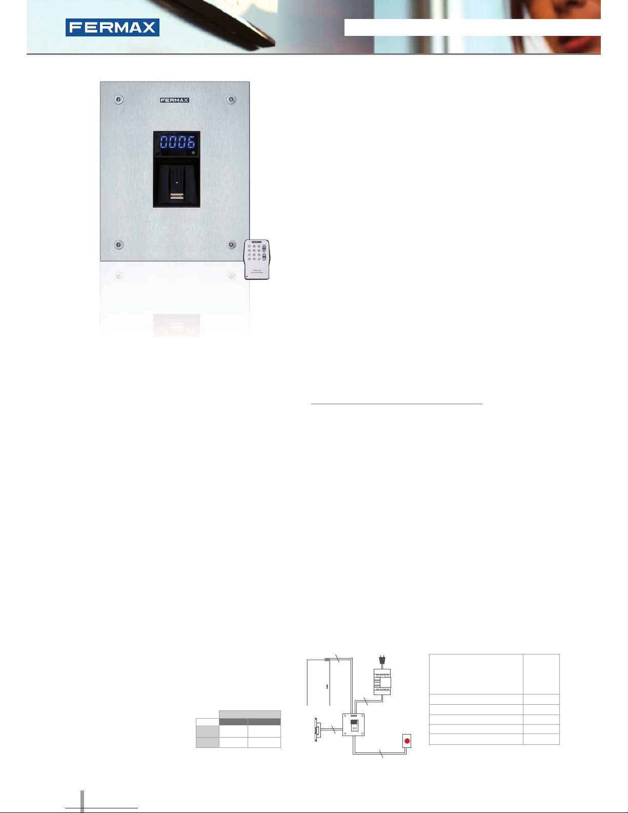
Marine Fingerprint
Ref.5474
Fingerprint
• Biometric access fingerprint reader with capacitive sensor.
Identifies the user by way of their fingerprint (a unique,
unrepeatable characteristic). With built-in proximity reader
which functions as follows:
- Some people have fingerprints without the necessary
information for authorization in a biometric system. This applies
to 1% of the population. In these cases, use integrated
Proximity.
- Security mode: activates dual security, (Fingerprint+Card) for
the same User.
• Integrated within a 2.5mm stainless steel Marine panel.
• Flush mounted (ref.4641, including box) or surface
installation (ref.4701, optional).
• Recommended for interior and exterior use.
• Reader and controller integrated within the same module.
• Can operate as a stand-alone or centralised system
(dipswitch configurable).
Configuration as a STAND-ALONE system:
• Capacity (no. users):
- 4.500 users in 1 fingerprint per person mode.
- 2.970 users in 2 fingerprints per person mode.
• Acoustic and visual confirmation using status and display
LEDs which indicate if a fingerprint has been accepted or
rejected.
• To ensure the ngerprint is read correctly, slide your nger along
the reader with a downwards movement (from top to bottom),
at a uniform speed and exerting slight pressure.
• Includes a software CD and infrared remote keypad.
PROGRAMMING
Programming can be done manually or by PC.
The system is programmed with a master print
(Administrator) and a remote infrared keypad. The PC
programming software can be downloaded from www.
fermax.com. The «Clone» option is available: it is used to
copy all data entered in one reader into another.
The fingerprint reader is located in the exterior area. The rest of the
devices are connected to this module and they are installed in the
building's interior: power supply and lock-release. An exit button
can be used optionally.
INSTALLATION
Dimensions: (horizontal)x(vertical)x(depth) mm
SPECIFICATIONS
• Dimensions:
* Reader
* Flush Mounted Box
* Surface Box
• Environmental Protection (IP)
• Anti-Shock Protection (IK)
• Power Supply (V)
• Consumption (mA) S/lock-release
• Operating Temperature
150x180
130x160x55
154x184x55
43
08
12V (ac/dc)
118/173
-10º to 55ºC
Lock-Releases
Exit Button
Power
Supply
Ref.5474
230Vac
2
2
2
2
024
STAND-ALONE
12Vdc
12Vac
30708
3071
2888
2880
* Door lock recommended.
Normal
References
Reinforced
TECHNICAL FEATURES
• Relay lock-release activation.
Programmable from 01 to 99 seconds.
• Acoustic and visual status data.
• Reader with 2 status LEDs and a 7 segment 4 digit
display (helps with programming and status data).
• Manual programming using the infrared
remote control included or via PC software (card
activation/deactivation of fingerprints).
• Special Functions: free ngerprint button (trades)
and unblock fingerprint (lock-release always
activated).
• Door sensor and exit button control.
• Auxiliary Relay for other Functions. Door alarm and
forced door, panic alarm or intruder alarm (incorrect
fingerprint).
• Allows keypad connection for Security Mode
operation: in this case, the dual security would be
Fingerprint+Code, for the same User.
Built-in Proximity reader
Page 25
2011 ACCESS CONTROL 23
2011 ACCESS CONTROL 23
STAND-ALONE
12Vdc
12Vac
30708
3071
2888
2880
* Door lock recommended.
Normal
References
Reinforced
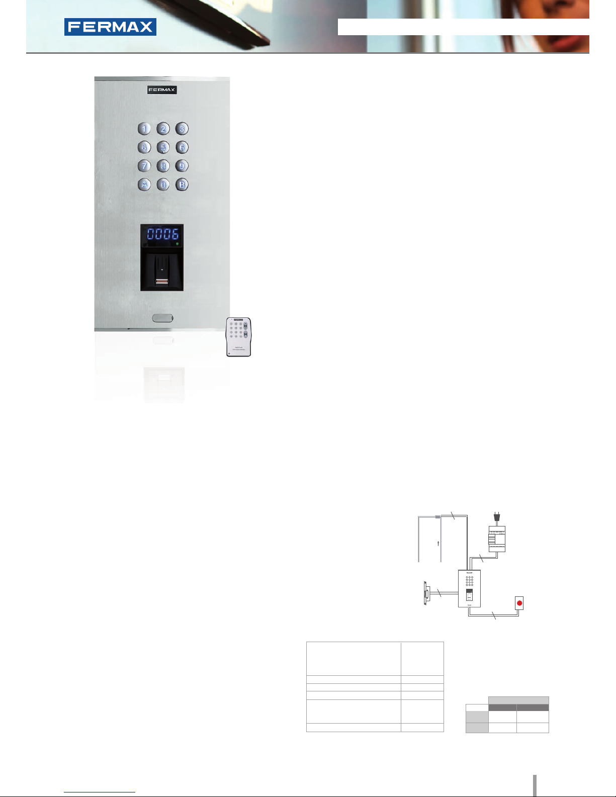
• There are a number of people whose ngerprints do not not have
the necessary information to be set up on a biometric system.
This applies to 1% of the population. In these cases, the use of an
alternative technology combined is recommended.
• Biometric access fingerprint reader with capacitive sensor.
Identifies the user by way of their fingerprint (unique and
unrepeatable characteristic). Built-in proximity reader. Reader also
includes a keypad. Functions as follows:
- For cases where ngerprints cannot be authorized, use integrated
Proximity or Keypad.
- Segurity mode: The reader includes a keypad for dual security
function: Fingerprint+Code, for the same User.
• Integrated in Cityline aluminium panel.
• Flush mounted (ref.8855, including box) or surface mounted
(ref.7065, optional).
• Recommended for interior and exterior use.
• Reader and controller integrated within the same module.
• Includes a software CD and infrared remote keypad.
PROGRAMMING
Programming can be done manually or via PC. In manual mode the
system is programmed using a master fingerprint (administrator)
and an infrared remote keypad. The PC programming software
can be downloaded from www.fermax.com. It allows the «Clone»
option which allows the user to copy all data from one reader to
another.
INSTALLATION
Cityline Keypad+Fingerprint
Ref.6996
Keypad and Fingerprint
Dimensions: (horizontal)x(vertical)x(depth) mm
SPECIFICATIONS
• Dimensions:
* Reader
* Flush Mounted Box (included)
* Surface Box (optional)
• Environmental Protection (IP)
• Anti-Shock Protection (IK)
• Power Supply (V)
• Consumption (mA) S/lock-release
* Fingerprint
* Keypad
• Operating Temperature
130x246
115x233x45
130x246x33
43
07
12V (ac/dc)
118/173
40/110
-10º to 55ºC
Lock-Release
Exit Button
Power Supply
Ref.6996
230Vac
2
2
2
2
024
TECHNICAL FEATURES
FINGERPRINT
• Operating Options (no.of users):
- 4.500 users in 1 fingerprint per person mode.
- 2.970 users in 2 fingerprints per person mode.
• Relay lock-release activation.
• Acoustic and visual status data.
• Manual programming using the infrared remote control
included or via PC software (card activation/
deactivation of fingerprints).
• Reader with 2 status LEDs and a 7 segment 4 digit
display (helps with programming status).
• Special Functions: free access ngerprint button
(trades) and unblock fingerprint (lock-release always
activated).
• Door sensor and exit button control.
• Auxiliary Relay for other Functions. Door alarm and
forced door, panic alarm or intruder alarm (incorrect
fingerprint).
MEMOKEY (KEYPAD)
The identifier is not material since it is memorized by
the user. The user code is entered via the keypad.
Access control keypad allows to open the door by
entering a previously programmed 4 or 6 digit code.
Built-in Proximity reader
Page 26
24 2011 ACCESS CONTROL
2011 ACCESS CONTROL 25
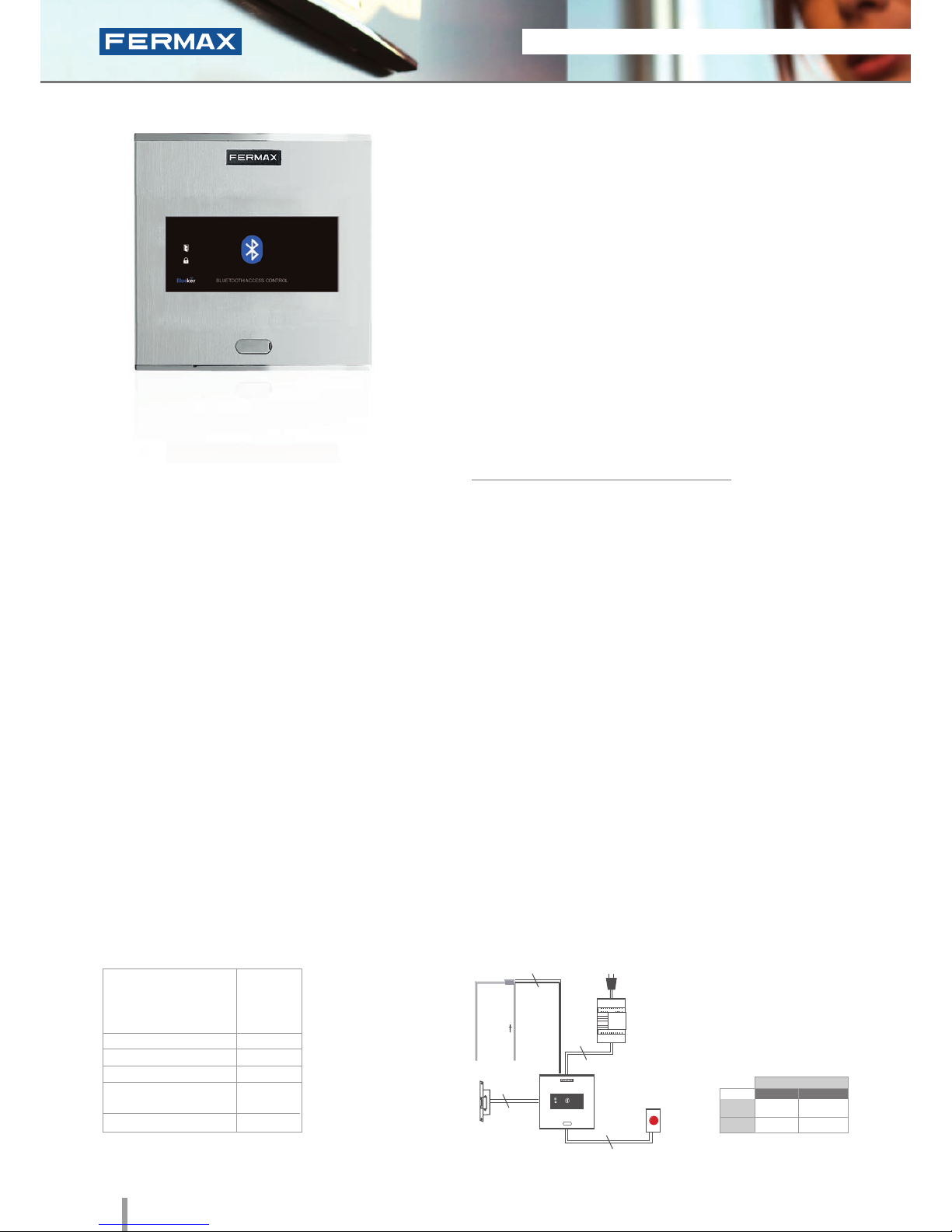
Cityline Bluetooth
Ref.6993
Bluetooth
• Access control reader which operates by means of telephones
equipped with Bluetooth technology where the mobile
telephone acts as a user identifier.
• Integrated within the Cityline aluminum panel.
• Flush mounted (ref.8948, including box) or surface installation
(ref.7061, optional).
• Recommended for interior and exterior use.
• Reader and controller integrated within the same module.
• Can operate as a stand-alone or centralised system
(congurable using dipswitch SW1).
Configuration as a STAND-ALONE system:
• Capacity based on chosen operating mode.
Operation options:
- Authorised telephones: automatic door opening or using a PIN
request and conrmation (3 modes).
Capacity: 40 mobile telephones.
- Any phone: PIN request. Capacity: Unlimited.
• Acoustic and visual confirmation using status LEDs which
confirm if a mobile phone has been accepted or rejected.
• Congurable reading range: 2m, 9m or up to 20m.
• Congurable repetition time.
PROGRAMMING
TECHNICAL FEATURES
This can be done in 2 ways: via mobile phone with bluetooth
connectivity (master mobile) using a list of commands or alternatively
via PC/PDA (with a bluetooth connection).
The «FermaxPC» programming software can be downloaded from
www.fermax.com
• Relay lock-release activation. Programmable from
01 to 99 seconds.
• Exit button input.
• Operation options:
1. Working with a list of authorised phones.
This is a list recorded on the receiver and determines
which telephones can open the door. List Capacity:
up to 40 different mobile telephones.
This working mode has three possible options:
- Automatic Mode (Without PIN): The door opens
when it detects the presence of an authorised phone.
- Request Confirmation: When the receiver detects
a phone on the list, it requests confirmation to open
the door. The user must press the 1 key and Accept
to open the door.
- Request PIN : When the receiver detects a
phone on the list it requests the PIN (4-digit code
configurable by the administrator).
2. Working without an authorised telephones list
(default conguration). The PIN will be requested for
any mobile phone with activated bluetooth within
range, and only if entered correctly the lock release
will be activated. Unlimited number of mobile phones.
Dimensions: (horizontal)x(vertical)x(depth) mm
SPECIFICATIONS
• Dimensions:
* Reader
* Flush Mounted Box
* Surface Box
• Environmental Protection (IP)
• Anti-Shock Protection (IK)
• Power Supply (V)
• Consumption (mA) S/lock rel.
• Operating Temperature
130x128
115x114x45
130x128x33
54
07
12V (ac/dc)
12Vac: 100
12Vdc 50
-15º to 55ºC
INSTALLATION
Lock-Release
Exit Button
Power
Supply
Ref.6993
230Vac
2
2
2
2
STAND-ALONE
12Vdc
12Vac
30708
3071
2888
2880
* Door lock recommended.
Normal
References
Reinforced
Page 27
2011 ACCESS CONTROL 25
2011 ACCESS CONTROL 25
STAND-ALONE
12Vdc
12Vac
30708
3071
2888
2880
* Door lock recommended.
Normal
References
Reinforced
PROGRAMMING
TECHNICAL FEATURES
• Relay lock-release activation. Programmable from
01 to 99 seconds.
• Exit button input.
• Operation options:
1. Working with a list of authorised phones.
This is a list recorded on the receiver and determines
which telephones can open the door. List Capacity:
up to 40 different mobile telephones.
This working mode has three possible options:
- Automatic Mode (Without PIN): The door opens
when it detects the presence of an authorised phone.
- Request Confirmation: When the receiver detects
a phone on the list, it requests confirmation to open
the door. The user must press the 1 key and Accept to
open the door.
- Request PIN : When the receiver detects a
phone on the list it requests the PIN (4-digit code
configurable by the administrator).
2. Working without an authorised telephone list
(default conguration). The PIN will be requested for
any mobile phone with activated bluetooth within
range, and only if entered correctly the lock release will
be activated. Unlimited number of mobile phones.
This can be done in 2 ways: via mobile phone with bluetooth
connectivity (master mobile) using a list of commands or alternatively
via PC/PDA (with a bluetooth connection).
The «FermaxPC» programming software can be downloaded from
www.fermax.com
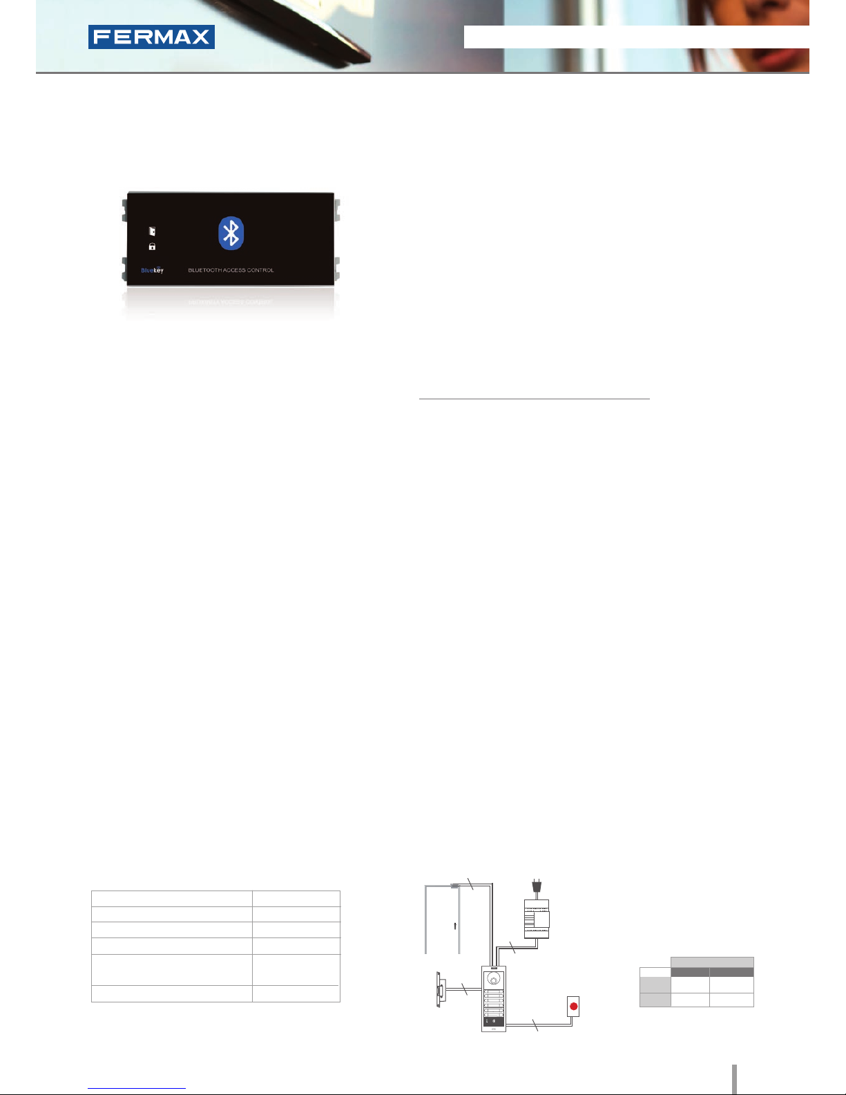
V Skyline Bluetooth
Ref.7441
Bluetooth
• Access control reader which operates by means of telephones
equipped with Bluetooth technology where the mobile
telephone acts as a user identifier.
• Access control module to be integrated within Skyline and
Cityline audio/video door entry system panels.
• Recommended for interior and exterior use.
• Reader and controller integrated within the same module.
• Can operate as a stand-alone or centralised system
(congurable using dipswitch SW1).
Configuration as a STAND-ALONE system:
• Capacity based on chosen operating mode.
Operation options:
- Authorised telephones: automatic door opening or using a PIN
request and conrmation (3 modes).
Capacity: 40 mobile phones.
- Any phone: PIN request. Capacity: Unlimited.
• Acoustic and visual confirmation using status LEDs which
confirm if a mobile phone has been accepted or rejected.
• Congurable reading range: 2m, 9m or up to 20m.
• Congurable repetition time.
The electronic or video door entry system panels are located in
the building's exterior. The panel can be configured in an intuitive
manner, including a bluetooth reader module for greater ease of
use and access security. The rest of the devices are connected to
this module and they are installed in the building's interior: power
supply and lock-release. An exit button can be used optionally.
INSTALLATION
Dimensions: (horizontal)x(vertical)x(depth) mm
SPECIFICATIONS
• Dimensions W:
• Environmental Protection (IP)
• Anti-Shock Protection (IK)
• Power Supply (V)
• Consumption (mA) S/lock-release
• Operating Temperature
105.2x47.5
54
07
12V (ac/dc)
12Vac: 100
12Vdc 50
-15º to 55º C
Lock-Release
Exit Button
Power Supply
Ref.7441
230Vac
2
2
2
2
Page 28
26 2011 ACCESS CONTROL
2011 ACCESS CONTROL 27
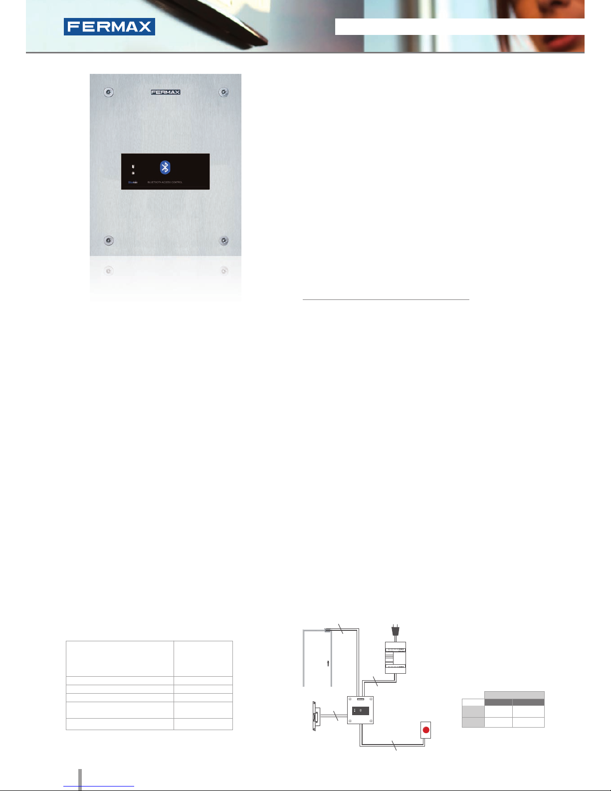
Marine Bluetooth
Ref.5473
Bluetooth
• Access control reader which operates by means of telephones
equipped with Bluetooth technology where the mobile
telephone acts as a user identifier.
• Integrated within a 2.5mm stainless steel Marine panel.
• Flush mounted (ref.4641, including box) or surface installation
(ref.4701, optional).
• Recommended for interior and exterior use.
• Reader and controller integrated within the same module.
• Can operate as a stand-alone or centralised system
(congurable using dipswitch SW1).
Configuration as a STAND-ALONE system:
• Capacity based on chosen operating mode.
Operation options:
- Authorised telephones: automatic door opening or using a PIN
request and conrmation (3 modes).
Capacity: 40 mobile phones.
- Any phone: PIN request. Capacity: Unlimited.
• Acoustic and visual confirmation using status LEDs which
confirm if a mobile phone has been accepted or rejected.
• Congurable reading range: 2m, 9m or up to 20m.
• Congurable repetition time.
The bluetooth reader is located in the exterior area. The rest of the
devices are connected to this module and they are installed in the
building's interior: power supply and lock-release. An exit button
can be used optionally.
INSTALLATION
SPECIFICATIONS
Dimensions: (horizontal)x(vertical)x(depth) mm
• Dimensions:
* Reader
* Flush Mounted Box
* Surface box
• Environmental Protection (IP)
• Anti-Shock Protection (IK)
• Power Supply (V)
• Consumption (mA) S/lock-release
• Operating Temperature
150x180
130x160x55
154x184x55
54
09
12V (ac/dc)
12VAc: 100
12Vdc 50
-15º to 55ºC
Lock-Release
Exit
Button
Power Supply
Ref.5473
230Vac
2
2
2
2
TECHNICAL FEATURES
PROGRAMMING
This can be done in 2 ways: via a mobile phone with bluetooth
connectivity (master mobile) using a list of commands or alternatively
via a PC/PDA (with a bluetooth connection).
The «FermaxPC» programming software can be downloaded from
www.fermax.com
• Relay lock-release activation. Programmable from
01 to 99 seconds.
• Exit button input.
• Operation options:
1. Working with a list of authorised phones.
This is a list recorded on the receiver and determines
which telephones can open the door. List Capacity:
up to 40 different mobile telephones.
This working mode has three possible options:
- Automatic Mode (Without PIN): The door opens
when it detects the presence of an authorised phone.
- Request Confirmation: When the receiver detects
a phone on the list, it requests confirmation to open
the door. The user must press the 1 key and Accept to
open the door.
- Request PIN : When the receiver detects a phone
in the list it requests the PIN (4-digit code congurable
by the administrator).
2. Working without an authorised telephone list
(default conguration). The PIN will be requested for
any mobile phone with activated bluetooth within
range, and only if entered correctly the lock release will
be activated. Unlimited number of mobile phones.
STAND-ALONE
12Vdc
12Vac
30708
3071
2888
2880
* Door lock recommended.
Normal
References
Reinforced
Page 29
2011 ACCESS CONTROL 27
2011 ACCESS CONTROL 27
STAND-ALONE
12Vdc
12Vac
30708
3071
2888
2880
* Door lock recommended.
Normal
References
Reinforced
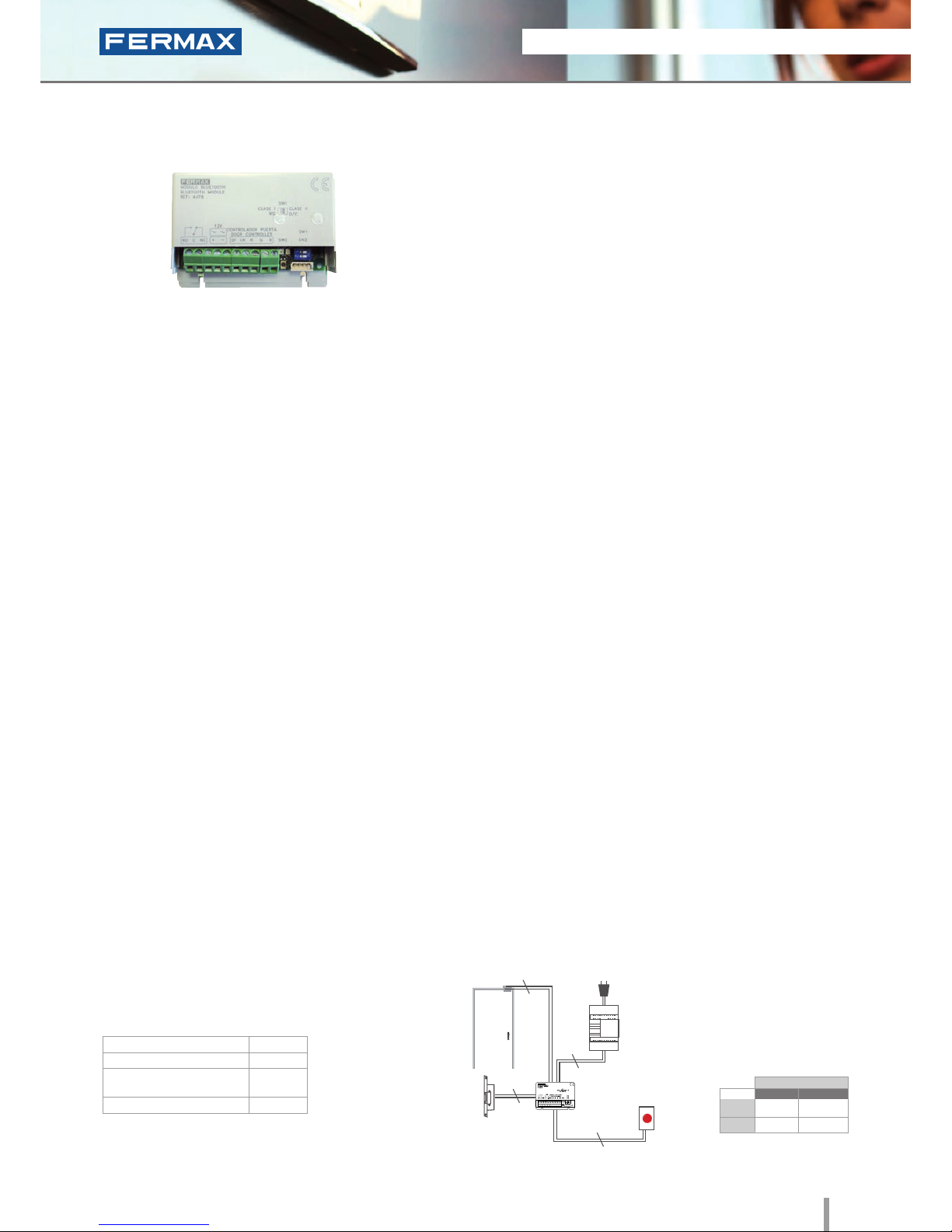
Mini Bluetooth
Ref.4479
Bluetooth
• Access control reader which operates by means of telephones
equipped with Bluetooth technology where the mobile
telephone acts as a user identifier.
• Reduced size module to be setup in the circuit box or in the
FERMAX audio/video door entry panel's flush mounted box.
• Reader and controller integrated within the same module.
• Can operate as a stand-alone or centralised system
(congurable using dipswitch SW1).
Configuration as a STAND-ALONE system:
• Capacity based on chosen operating mode.
Operation options:
- Authorised telephones: automatic door opening or
using a PIN request and conrmation (3 modes).
Capacity: 40 mobile phones.
- Any phone: PIN request. Capacity: Unlimited.
• Congurable reading range: 2m, 9m or up to 20m.
• Congurable repetition time.
PROGRAMMING
TECHNICAL FEATURES
The electronic or video door entry system panels are located
in the building's exterior. The mini-bluetooth module can be
installed internally within the flush mounted box on the panel
for greater ease of use and access security. Another option
would be to set it up internally in the circuit box. The rest of the
devices are connected to this module and they are installed in
the building's interior: power supply and lock-release. An exit
button can be used optionally.
INSTALLATION
Dimensions: (horizontal)x(vertical)x(depth) mm
SPECIFICATIONS
• Dimensions:
• Power Supply (V)
• Consumption (mA) S/lock-release
• Operating Temperature
86x60
12V (ac/dc)
12VAc: 100
12Vdc 50
-10º a 55ºC
This can be done in 2 ways: via a mobile phone with bluetooth
connectivity (master mobile) using a list of commands or
alternatively via a PC/PDA (with a bluetooth connection).
The «FermaxPC» programming software can be downloaded
from www.fermax.com
• Relay lock-release activation.
Programmable from 01 to 99 seconds.
• Exit button input.
• Operation options:
1. Working with a list of authorised phones.
This is a list recorded on the receiver and
determines which telephones can open the door.
List Capacity: up to 40 different mobile telephones.
This working mode has three possible options:
- Automatic Mode (Without PIN): The door opens
when it detects the presence of an authorised
phone.
- Request Confirmation: When the receiver detects
a phone on the list, it requests confirmation to
open the door. The user must press the 1 key and
Accept to open the door.
- Request PIN : When the receiver detects a
phone on the list it requests the PIN (4-digit code
configurable by the administrator).
2. Working without an authorised telephones list
(default conguration). The PIN will be requested for
any mobile phone with activated bluetooth within
range, and only if entered correctly the lock release
will be activated. Unlimited number of mobile phones.
Lock-Release
Power Supply
Ref.4479
230Vac
2
Exit
Button
2
2
2
Page 30
28 2011 ACCESS CONTROL
2011 ACCESS CONTROL 29
Trinary RF Dual
Channel Emitter
Ref.79561
Radio Frequency
• 433.92 MHz radio frequency emitter.
• Trinary technology
• Innovative and very robust design.
• Dual channel emitter that can activate two relays.
• Conguration of the required sequence using microswitches.
• Simplicity and ease of use.
COMPATIBLE WITH:
INSTALLATION
The reader is located in the exterior area. The rest of the
devices are connected to this module and they are installed in
the building's interior: power supply and lock-release. An exit
button can be used optionally.
TECHNICAL FEATURES
• Dip-switch conguration
(8 microswitches at 3 positions).
• Unlimited number of users permitted
by the receiver.
• Includes a 12Vdc battery
• Range: 30m.
• Frequency: 433.92 MHz.
• Consumption when transmitting: 10mA
• Standby Consumption: 0,1mA
• Dimensions: 53x63x13.
• Power supply: 12 Vc battery.
Ref.7952 mono-channel garage receiver.
Ref.7900 PCB mono-channel receiver (OEM).
Ref.7903 DIN rail mono-channel receiver.
RF Emitter
Ref.79561
Lock-Release
Receiver
2
STAND-ALONE
12Vdc
12Vac
30708
3071
2888
2880
* Door lock recommended.
Normal
References
Reinforced
Page 31

2011 ACCESS CONTROL 29
2011 ACCESS CONTROL 29
STAND-ALONE
12Vdc
12Vac
30708
3071
2888
2880
* Door lock recommended.
Normal
References
Reinforced
COMPATIBLE WITH:
TECHNICAL FEATURES
• Includes a 25cm rigid antenna.
• Alternatively the user can use card ref.7934,
which converts the receiver into a dual-channel
device which activates a second relay.
• Receiving frequency: 433.92 MHz.
• Sensitivity: 3mV.
• Relay Contact: 2A max.
• Power supply: 220Vac / 50Hz.
• Consumption: 110mA on standby.
• Dimensions: 90x165x55.
Trinary emitters (ref.79561).
Garage Receiver
Ref.7952
Radio Frequency
• 433.92 MHz monochannel receiver.
• Trinary technology.
• The receiver accepts all emitters (ref.7956) with the
same code.
• When receiving the code, the receptor closes the
circuit which activates the lock-release or door
mechanism.
• Assembled in an ABS airtight box (IP65).
• Programmed via 8 micro-switches with 3 positions each.
INSTALLATION
RF Emitter
Ref.79561
Ref.7952
Ref.7934
Lock-Release
Alarm
2
2
Page 32

30 2011 ACCESS CONTROL
2011 ACCESS CONTROL 31
Mono-Channel
Receiver
Ref.7900
Radio Frequency
• 433.92 MHz monochannel receiver.
• Trinary technology.
• The receiver accepts all emitters (ref.79561) which are
coded with the same code.
• These can be installed in the FERMAX door entry/video
door entry panels' flush mounted box.
• It could be installed 2 independent receivers with the same
two-channel transmitter (ref.79561).
COMPATIBLE WITH:
INSTALLATIONTECHNICAL FEATURES
• Conguration by means of trinary dipswitch.
(8 microswitches at 3 positions).
• Power supply: 12Vdc / 12Vac
• Frequency: 433.92 MHz.
• 12Vac Output to activate the lock-release.
• Output for button connection to open the door from
the interior.
• Dimensions: 20x70x60.
Trinary emitters (ref.79561).
Ref.7900
Installed inside
the flush-mounted box.
Exit Button
RF Emitter (ref.79561).
Power Supply
230Vac
Lock-Release
2
2
2
STAND-ALONE
12Vdc
12Vac
30708
3071
2888
2880
* Door lock recommended.
Normal
References
Reinforced
Page 33

2011 ACCESS CONTROL 31
2011 ACCESS CONTROL 31
Ref.7903
Power Supply
230Vac
12Vac
Lock-Release
2
2
Exit Button
2
STAND-ALONE
DIN Rail Receiver
Ref. 7903
Radio Frequency
• 433.92 MHz monochannel receiver.
• Trinary technology.
• The receiver accepts all emitters (ref.79561) coded with
the same code.
• Includes the RF receiver in DIN 6 format and the
transformer or power supply.
• Recommended for shops, offices and businesses.
COMPATIBLE WITH:
INSTALLATIONTECHNICAL FEATURES
• Direct connection to 220Vac/50Hz.
• Setup on DIN rail or wall.
• Output for button connection to open the door from
the interior.
• Frequency: 433.92 MHz.
• Conguration by means of trinary dipswitch.
(8 microswitches at 3 positions).
• 12Vac output to activate the lock-release.
• Specication: DIN 6 elements.
• Dimensions: 105x90x60.
Trinary emitters (ref.79561).
Circuit Box
Emitter ref.79561
ref.7903
* Door lock recommended.
12Vac
3071 2880
Normal
References
Reinforced
Page 34

32 2011 ACCESS CONTROL
2011 ACCESS CONTROL 33
Digital RF Emitter
Ref.24651
Radio Frequency
• 433.92 MHz radio frequency emitter.
• Digital technology.
• Innovative and very robust design.
• Dual channel which can activate two relays.
• Secure, unique code, which is non-configurable and
corresponds to the emitter series.
• The emitters must be activated/deactivated on the
receivers.
COMPATIBLE WITH:
TECHNICAL FEATURES
• Code which is unique and exclusive to the emitter.
• Includes a 12Vdc battery.
• Distance: 30m.
• Frequency: 433.92 MHz.
• Consumption when transmitting: 10mA.
• Standby Consumption: 0.1mA.
• Dimensions: 53x63x13.
Stand-alone Chalet receptor (ref.7960).
INSTALLATION
Lock-Release
Power Supply
230Vac
RF Receiver ref.7960RF Emitter ref.24651
2
2
STAND-ALONE
12Vdc
12Vac
30708
3071
2888
2880
* Door lock recommended.
Normal
References
Reinforced
Page 35

2011 ACCESS CONTROL 33
2011 ACCESS CONTROL 33
STAND-ALONE
12Vdc
12Vac
30708
3071
2888
2880
* Door lock recommended.
Normal
References
Reinforced
Villa Receiver
Ref.7960
• 433.92 MHz mono-channel receiver.
• Digital Technology.
• Only authorised digital (ref.24651) or dual emitters
(ref.25511) will activate the device.
• Reduced size which allows them to be installed in
electrical systems (mounted within standard 10x10cm
boxes).
• The emitters must be setup on the receiver.
COMPATIBLE WITH:
INSTALLATIONTECHNICAL FEATURES
• 12Vac/12Vdc Power Supply.
• Allows up to 10 emitters (users) to be stored in
the memory with individual, unique codes.
• Relay lock-release activation. Programmable time.
• Exit button input.
• Frequency: 433.92 MHz.
• Programming the door opening time via the dip-switch.
• Dimensions: 62x70x20.
Digital emitters (ref.24561) or dual emitters
(ref.25511).
Lock-Release
Power Supply
230Vac
RF Receiver ref.7960RF Emitter ref.24651 ó
ref.25511
2
2
Radio Frequency
Page 36

34 2011 ACCESS CONTROL
2011 ACCESS CONTROL 35
Dual RF emitter
Ref.25511
• 433.92 MHz radio frequency emitter.
• Dual Technology.
• Innovative and very robust design.
• Dual-Channel emitter which can activate two relays.
• Secure, unique code, which is non-configurable and
corresponds to the emitter series.
• The emitters must be activated/deactivated on the
receptors.
• Internally integrates the proximity card’s electronics
which means it can be used as a bi-channel emitter or as
an alternative to proximity cards or keyrings.
COMPATIBLE WITH:
INSTALLATION
TECHNICAL FEATURES
• In addition to RF functions, it incorporates proximity
card electronics which can be used with any
proximity reader.
• Includes a 12Vdc battery.
• Range: 30m.
• Proximity Reader Distance: 1cm.
• Frequency: 433.92 MHz.
• Consumption when transmitting: 10mA.
• Standby Consumption: 0.1mA.
• Dimensions: 53x63x13.
Stand-alone Villa receiver (ref.7960).
Lock-Release*
Power Supply
230Vac
Garage Receiver ref.7960
RF Emitter ref.25511
2
2
Radio Frequency
Dimensions: (horizontal)x(vertical)x(depth)mm
STAND-ALONE
12Vdc
12Vac
30708
3071
2888
2880
* Door lock recommended.
Normal
References
Reinforced
Page 37

2011 ACCESS CONTROL 35
2011 ACCESS CONTROL 35
STAND-ALONE
INSTALLATION DIAGRAMS FOR STAND-ALONE IN NETWORK FINGERPRINT READERS
Page 38

Page 39

CENTRALISED
ACCESS CONTROL
Page 40

38 2011 ACCESS CONTROL
2011 ACCESS CONTROL 39
1. GENERAL FEATURES
For large systems with various access points and extensive functions.
Allows complete management of a system with several access points and advanced access control functions: restrictions
by user groups, both in terms of space (zones) and time (timetables), one-way function, restriction of numbers, greater user capacity,
activation of devices from the reader, recording of incidents for subsequent consultation, control or security centre.
Also permits the integration of additional services within the access control system: intercommunication, alarms, automation, etc.
- INTERCOMMUNICATION. For those access points where you need to grant access to external personnel.
A button is pressed to contact the central guard unit, and from there access is granted.
- TECHNICAL OR INTRUDER ALARMS. Each entrance and exit can be programmed with a detection and intervention time.
The alarms appear on the computer screen and on the central guard unit.
- AUTOMATION. Relay activation for certain events. Activation of devices from the readers (alarm activation/deactivation
on entry or exit). Weekly programmer which can plan up to 32 daily activities for individual or groups or sensors and relays.
Allows automatic connection with lighting, motor, heating, air conditioning, sprinkler systems, etc.
Requires a Central Unit to manage the system and software (Windows operating system), to program the system via a PC.
The connection between the PC and the system can be direct (RS-485) or remote (IP). The data can be updated and the
system monitored from different PCs (multi-station).
Centralised access control systems are also known as CLASS III access control systems.
The system uses a 2 wire BUS and shielded twisted pair. The readers connect to the panel BUS and the relay and sensor
decoders to the Central Unit decoder BUS.
2. CENTRALISATION
System centralisation involves a central unit, a power supply and relevant PC connection devices.
We recommend you to use an emergency power supply system (battery).
In systems with large distances, you will need to install additional power supplies at the access points in order to avoid drops in
voltage with wiring.
CENTRALISED
Page 41

2011 ACCESS CONTROL 39
2011 ACCESS CONTROL 39
4. READER SECURITY TYPE
Depending on the level of security required, the readers comprise two
types: WITH integrated controller and WITHOUT integrated controller.
- Readers with integrated controller. Models: MDS/CAC.
Installation is easier but the level of security is lower by leaving the
control circuit on the exterior (of the reader). All devices connect directly
to the reader: lock-release, door sensor (if required) and exit button.
- Readers without integrated controller. Models: Wiegand-26/
Data Clock.
A door controller is required. This is installed in the interior area (secure
area) and the reader on the exterior. All devices are connected to the
door controller: the lock-release, door sensor (if required), exit button,
etc. and therefore are not subject to interference.
Readers are recommended for more secure applications.
KEYPAD. The user should enter a code on the keypad. It is the most
economical model as it does not use identifiers. The same code can
be used by various users.
PROXIMITY. The identifier is a card (similar to a credit card) or a
proximity fob. The identifier is swiped by the reader at a distance
of several centimetres. The reading is facilitated by means of radio
frequency data transmission. This is the easiest and most secure
method.
BLUETOOTH. Access control functions are provided by way of mobile
phones with Bluetooth technology. The telephone system itself identifies
the user. The advantage of this system is the reader's operating distance,
which makes it very useful for vehicle and pedestrian accesses.
BIOMETRIC FINGERPRINT. Biometric fingerprint access reader with
capacitive sensor. Identifies the user by its fingerprint (feature which
is unrepeatable and unique to each person), offering a greater level of
security than any other system using another type of identifier.
RADIO FREQUENCY. This technology is mainly used in
garage accesses given the flexibility allowed by the large
distance between the identifier (control) and the receiver.
3. READER TECHNOLOGY
There are several types of technologies depending on the
interaction between the identifier and the reader.
Page 42

40 2011 ACCESS CONTROL
2011 ACCESS CONTROL 41
CAC Central Unit
Ref.4410
PROGRAMMING
• 2.048 users.
• 32 access points.
• Continual access testing.
• Register of the last 3.000 incidents (entries, exits,
access denied, alerts, etc.) within the memory
without the need to download it to the PC.
• Option to connect readers with or without an
integrated controller (via the door controller).
All programming is done using the CAC software and
from a duly authorised computer. CAC software is
included on the Central Unit in CD format or can be
downloaded from www.fermax.com
System centralisation involves a central unit, a power
supply and relevant PC connection devices. We
recommend to use an emergency power supply
system (battery).
In systems with large distances, you will need to install
additional power supplies at the access points in order
to avoid drops in voltage with wiring.
Installation is done using 2 wire BUS and a shielded
twisted pair. Interconnection of various central units
requires a further wire.
INSTALLATION
Dimensions: (horizontal)x(vertical)x(depth) mm
• Dimensions
• DIN rail xed in place or 2 screws to wall
• Surface Box (optional)
• Power Supply (V)
• Consumption (mA) S/lock-release
• Operating Temperature
175x90x40
130x128x33
12Vdc
150
0º to 60ºC
SPECIFICATIONS
TECHNICAL FEATURES
• Central Unit for large access control systems. Manages up to
32 access points or doors with a total of 2.048 users.
• Allows the installation of 1 MDS Digital Guard Unit (just one
throughout the entire system).
• A maximum of 64 Central Units can be connected
(2.048 access points).
• Incorporates the CAC management software in CD format.
This software is comprised of various applications: "Server
Applications" and "Client Applications".
- Server Applications: developed for the installer.
· CAC Database Server: this is the application that manages
the database which stores all the information and which
transmits all data to the rest of the user applications and to the
CAC Server.
· CAC Server: this is the application where the installer defines
the system's hardware elements (central unit, readers, decoders,
etc).
All CAC systems have one unique CAC Server and CAC
Database Server.
· Client Applications: developed for the user via a simple,
intuitive, graphic interface. Multi-Station Applications.
· CAC Access: User and Authorisation Management event
viewing, etc.
· CAC Attendance: Presence Control Management (compilation
of employee payslips). Allows you to capture, define and control
the hours worked by employees within a company using the
same access control readers.
• Ability to manage 1.000 intercommunication panels, 1.000
sensors and 1.000 relays.
• Local Connection (USB, RS-232) or remote connection (IP) to the
corresponding module (see accessories).
Reader
Reader Reader
Up to 32 readers
Up to 32 readers
2
3
2
3
2
2
Twisted Pair
Twisted
pair
twisted
pair
Up to 64 Central Units
C.U.
(ref.4410)
C.U.
(ref.4410)
C.U.
(ref.4410)
Twisted Pair
Power Supply
Twisted Pair
2
2
Up to 32 readers
CENTRALISED
Page 43

2011 ACCESS CONTROL 41
2011 ACCESS CONTROL 41
and Database Server
Server Applications
Server Applications: these are applications developed for the
installer.
· CAC Database Server: this is the application that manages the
database where all information pertaining to the systems (users,
incidents, etc..) is stored, and which manages the rest of the user
applications and the CAC Server itself.
· CAC Server: this is the application where the installer defines
the system's hardware elements which, in turn, act as the server
for the remaining CAC architecture client applications and as a
communication server with the CAC system.
The PC where the CAC Server is installed should be connected
directly to the system through an appropriate interface.
The whole CAC system must have a single CAC Server
application and CAC Database.
• Sections: The CAC Control Server application, allows the system to be organised into sections (up to 4 different sections).
In systems with a high number of central units or central units which are very far from others, the creation of sections allows to
manage all the central units from the same PC without needing to connect all the central units by way of a FXL network, creating
one single system.
• CAC Central Unit: A CAC access control system will use between 1 and 64 CAC central units. Each central unit is inserted into
the CAC Control Server application, in its corresponding section. It is also assigned a description and central unit number.
• Doors: A door corresponds to each one of the readers or door controllers (DC) of the installation. Each DC may manage up to 2
readers (Entrance/Exit) from the same door.
In the CAC Server application, for each central unit, the same number of doors and readers or DCs are added, and these can be
connected to the the central units in the system (from 1 to 32 readers or door controllers per central unit).
• Areas: Areas only need to be defined where limits on capacity are required (capacity control).
• Antipassback: The anti-passpack function prevents a user who has accessed the building by means of an entrance door to
re-enter the building (via any entrance door) without having previously exited the building. Two levels of antipassback: pedestrian
and vehicular.
• Sensor Groups - Individual Sensors (Capacity to manage 1.000 sensors): You only need to dene groups of sensors or
individual sensors where there are sensor decoders in the building.
• Relay Groups - Individual Relays (Capacity to manage 1.000 relays): You only need to dene groups of relays or individual
relays where there are relay decoders in the building.
• Planner: Allows the user to dene up to 32 automation plans to control various devices.
• Sabotage Control: Allows you to activate the sabotage detection function on the decoder bus (where relay decoders, sensor
decoders or panel decoders are set up for intercommunication).
• Automatic switch to winter/summer daylight saving time.
TECHNICAL FEATURES
CENTRALISED
Page 44

42 2011 ACCESS CONTROL
2011 ACCESS CONTROL 43
CAC Access
Software
Customer Applications
Client Applications: these are applications developed by the
user and they allow them to get maximum advantage from
the CAC system.
Using CAC Access you can manage and control users,
doors and incidents, create access restrictions and generate
reports.
• User friendly graphic interface, which is simple and
intuitive. All options are shown on a hierarchical tree.
• Requires to have the CAC Database Server software
installed (manages the MySQL database) and CAC Server.
• 2.048 users.
• 64 groups of users (profiles). Each one denes the restrictions to be applied to the group by assigning up to
3 Areas and 3 Timetables.
• 4 special profiles without user restrictions.
• 32 Areas. Dene the doors through which access is permitted.
• 32 Timetables Dene the periods of time in which access is permitted to users.
• Holidays (20 holidays and 3 holiday periods).
• Online incident register (entries, exits, accesses denied, alerts, etc.).
• 32 weekly activation plans (sensors and relays).
• Restriction on the number of people in certain rooms or areas.
•Temporary blocking of users individually or by groups. They are not permitted to access until they are unblocked.
• Activation of devices associated with each user, on swiping their identifier by a reader.
• Generating reports.
• Backup copies.
TECHNICAL FEATURES
CENTRALISED
Page 45

2011 ACCESS CONTROL 43
2011 ACCESS CONTROL 43
CAC Software
Attendance
Customer Applications
Client Applications: these are applications developed by the
user and they allow them to get maximum advantage from the
CAC system.
The CAC Attendance application allows you to manage
presence control This application is designed for personnel
control by way of clock-ins which are recorded at a presence
control terminal via a personal identifier (proximity card, keyring...
etc).
Subsequently it allows the compilation of the information for
schedule management, calculation of time worked, personnel
monitoring, calculation of justified absences and the parameters
specied for each employee. The CAC Attendance application
allows you to capture, define and control the time spent by a
company's employees via a CAC system.
Although the ATTENDANCE client application may be installed
on various computers on the same network, only one instance
can be executed. If there is another instance operating the
application will advise us.
• User friendly graphic interface which is simple and intuitive.
All options are shown on a hierarchical tree.
• Requires that you have the CAC Database server installed
(manages the MySQL database) and CAC Server.
• Flexible Clock-In Register.
• Automatic Generation of Presence Events.
• Profile Based Assignment.
- The application of schedules to dates is done by means of profiles.
- A profile can have various different schedules applied to the same time period if they don't overlap.
• Multiple Time Periods. Within each timetable various periods can be dened which indicate the period of time the user should
be present.
• Definition of courtesy times within time slots. Within each time slot there is an option to specify a clock-in and clock-out
margin.
• Different Schedule Types: rigid and flexible.
- Rigid Schedules: Comprised of a series of time slots which indicate the period when the employee should be present.
This time is calculated adding various time slots.
- Flexible Schedules: Comprised of one or various slots which indicate the time during which the employee can be present, but
TECHNICAL FEATURES
CENTRALISED
Page 46

44 2011 ACCESS CONTROL
2011 ACCESS CONTROL 45
the total presence time which must be fulfilled each day is indicated separately.
• Night shifts can be defined.
• Justified absences can be defined.
- If you know a person is going to be absent for one day during a set period a justified absence can be included on this day and
the absence type identified.
- The assignment of holidays is done by way of justified absences identified as holidays.
• Defining Working Days. You can dene certain weekdays as working days (set by default from Monday to Friday) during which
the presence data will be compiled.
• Defining Holidays. Annual holidays can be defined, and are set commonly for all employees independently of their justified
absences.
• Real time control of sign-ins and people present currently or at earlier points in the relevant slot.
• Definition of the intervals between sign-ins in each time slot based on which reports on events can be generated.
• Definition of opening and closing thresholds which indicate the minimum time between two clock-ins for an event to be
opened or closed.
• Theoretical Hours Check. Hours which according to the schedule each employee must work within a specic time period.
• Calculation of the real hours worked by each employee.
• Control over excess or insufficient hours worked by the employee.
• Control over clock-in errors. Expressing them as presences pending closure. These can be rapidly converted to presences in
one sole action.
• Manual correction of employee presence anomalies. Manual editing, deletion and creation of events.
• Definition of types of justifications so as to be able to assign them to absences that have been justified.
• Definition of clock-in codes. These will be assigned to the events generated by these clock-ins. These are sent from readers
with keypads.
•Detailed Event Check. You can check the clock-ins which have resulted in the generation of an event, the duration of the event,
etc...
• Filtered Presence View. Possibility of filtering an employee's events.
• Automatic import of clock-ins from the central unit.
• Automatic Generation of Events. The event generation process occurs when there are clock-ins pending compilation and the
process button is activated.
• Backup and recovery of the presence database.
• With the application minimised it is possible to:
- Check if the employees are present.
- Show the clock-ins generated in the central unit and the user’s details in real time.
• Selection of the presence readers to be used. Any of those within the system can be selected or any reader can be connected.
CENTRALISED
Page 47

2011 ACCESS CONTROL 45
2011 ACCESS CONTROL 45
MDS Central Unit
Ref.2405
• Central Unit for large facilities with door entry systems and
combined with access control.
• Each Central Unit is able to manage up to 10.000 residences,
1.022 users and up to 32 video door entry panels, guard
units and access control systems.
• A maximum of 63 central units can be connected to the FXL
network. In this case only 31 panels can be connected per
central unit.
• Incorporates the Wincom+ management software in CD
format.
• Capacity to manage 1.000 intercommunication panels,
1.000 sensors and 1.000 relays.
• Local Connection (USB, RS-232) or remote connection (IP)
to the corresponding module (see accessories).
PROGRAMMING
• 1.022 users.
• 32/31 access points depending on the system.
• Register of the last 3.000 incidents (entries, exits,
access denied, alerts, etc) with the memory without
the need to download it to the PC.
• Option to connect readers with or without an
integrated controller (via the door controller).
All programming is done using Wincom+ software.
Wincom+ software is included in the Central Unit in CD
format or to can be downloaded from www.fermax.com
System centralisation involves a central unit, a power supply and
relevant PC connection devices.
We recommend you to use an emergency power supply system
(battery).
In systems with large distances, you will need to install additional
power supplies at the access points in order to avoid drops in
voltage with wiring.
INSTALLATION
Dimensions: (horizontal)x(vertical)x(depth) mm
SPECIFICATIONS
• Dimensions
• DIN rail xed in place or 2 screws to wall
• Surface Box (optional)
• Power Supply (V)
• Consumption (mA) S/lock-release
• Operating Temperature
175x90x40
130x128x33
12Vdc
150
0º to 60ºC
TECHNICAL FEATURES
Up to 32 elements
Video Panel
Video Panel
coax
coax
Twisted Pair
Twisted Pair
Twisted Pair
6
6
2
Central Unit (ref. 2405)
ref.2379
Reader
CENTRALISED
Door lock recommended:
12Vdc 30708 2888 29580
Normal Normal w/sensor
References
Reinforced
Page 48

46 2011 ACCESS CONTROL
2011 ACCESS CONTROL 47
Software Wincom+
The WinCom+ application allows you to program MDS
systems. The application was conceived so as to be
able to define simple systems (electronic door entry
system with central unit) and more complex systems
(various central units on a network with access control,
lift control, planner...).
The application in addition to programming the system
(group of central units) can receive incidents, define alert
messages on the screen, carry out a complete test of the
system (all devices on the system), make modifications,
additions, delete users, that is complete management
of all users on the system, (import/export of users via an
Excel sheet, searches, location of users by areas, rapid
addition of users by reading their proximity card, etc).
User friendly graphic interface which is simple and
intuitive in that all options can be viewed as part of a
hierarchical tree.
• 1.022 users.
• 64 groups of users (proles). Each one denes the
restrictions that apply to the group by assigning up to 3
Areas and 3 Schedules.
• 4 special proles without user restrictions.
• 32 Areas. Dene the doors through which access is
permitted.
• 32 Timetables. Denes the periods of time during which
access is permitted to users.
• Holidays (20 holidays and 3 holiday periods).
• Online incident register (entries, exits, access denied,
alerts, etc).
• 32 device activation weekly plans (sensors and relays).
• Limit on the capacity in certain rooms or locations.
• Lift Control.
• Activation of devices associated with each user on
swiping their identifier by a reader.
• Antipassback.
TECHNICAL FEATURES
CENTRALISED
Page 49

2011 ACCESS CONTROL 47
2011 ACCESS CONTROL 47
Ref.4420
• Door controller without memory.
• Manages the devices connected to each access
point: up to 2 readers (input/output), lock-release,
exit button, door sensor and free access button.
• Installed in the building's interior and separate
from the reader to ensure greater security.
• Wiegand-26 Input, magstrip or ibutton.
• Door Controller-Central Unit Wiring: 2 wires (power supply)+shielded twisted pair (data).
• Includes a dipswitch for conguration:
- Door Nº: the access/door number managed (0....31).
- Reader Type: type of readers connected (Wiegand-26, Dallas i-Button, Data/Code).
- Identifier.
• The DC is able to control the following elements for an access point:
- Input and output reader located one outside the building and the other inside (optional). Maximum distance between door
controller and reader: 10 metres. Note: with Central Units ref.2405 you can only connect 1 reader.
- An exit button which allows the door to be opened (pedestrian door) from inside the building. For vehicular doors, an induction
loop can be connected.
- A Trades button (commercial timetable) located outside the building, which allows the door to be opened within the established
timetable.
- A 4/6 status door sensor. In the case of vehicular doors, this allows a validation induction loop to be connected to a 10K
resistance that must be connected in parallel.
- Two relays. One of these can be used to control the lock-release, the other is used as an auxiliary relay and can be used to
control an associated door alarm.
• Allows the standard readers to be connected, there are four different types:
- Readers with data output in Wiegand-26 format.
- Readers with data output in MagStripe format (ABA Track II or Data/Clock).
- Dallas i-Button reader type.
- Matrix keypads with data output in 8-bit burst format.
• Vehicular access. Necessary for vehicular access. The controller should be installed according to the vehicular conguration.
In this case 2 vehicular presence detectors are required (induction loops). The rst should read the identier and the second should
record the number of vehicles (capacity) and confirm antipassback.
• Double Antipassback: pedestrian and vehicular.
Installation in 100x100mm circuit boxes or in surface boxes
using 2 screws (included).
INSTALLATION
Dimensions: (horizontal)x(vertical)x(depth) mm
SPECIFICATIONS
• Dimensions:
• Power Supply (V)
• Consumption (mA)
• Operating Temperature
85x88x25
12Vdc
15/100
0º to 60ºC
TECHNICAL FEATURES
Door controller
CENTRALISED
2
2
2
2
4
2
7
7
ref.4420
C.U. ref.4410
Entry Reader Exit Reader
Exit Button
Door Sensor
Lock-ReleaseExterior Interior
Alarm
Trades Button
024
Door lock recommended:
12Vdc 30708 2888 29580
Normal Normal w/sensor
References
Reinforced
Page 50

48 2011 ACCESS CONTROL
2011 ACCESS CONTROL 49
MDS/CAC
Cityline Keypad
Ref.6994
• Access control reader which allows the door to be opened
when a pre-programmed code of up to 6 digits is entered.
• Integrated within the Cityline aluminum panel.
• Flush mounted (ref.8948, including box) or surface
installation (ref.7061, optional).
• Recommended for interior and exterior use.
• Reader and controller integrated within the same module.
• Keypad reader with capacity for up to:
- 1.020 user codes with MDS central unit (ref.2405).
- 2.048 user codes with CAC central unit (ref.4410).
• Length 4 to 6 digits.
• Acoustic confirmation on pressing a button or indicating
that the code entered has been accepted/rejected.
• Lock-release button input, door sensor input
and lock-release relay.
• Reader - Central Unit Wiring: 2 wires (power
supply) + shielded twisted pair (data).
On a system with various
readers these can be connected in cascade.
• Includes a dipswitch for conguration:
- Door Number: the access/door number
(0..31).
- Lock-Release Opening Time (secs.):
* On MDS via dipswitch.
* On CAC software conguration.
• The lock-releases can be connected directly
to the reader and for systems with maximum
security use the relay decoder.
• To enter a user code press: «0+CODE».
Programming is done using the PC software relevant to the
central unit installed (ref.2405 or ref.4410).
PROGRAMMING
INSTALLATION
Dimensions: (horizontal)x(vertical)x(depth) mm
SPECIFICATIONS
• Dimensions:
* Reader
* Flush Mounted Box
* Surface Box
• Environmental Protection (IP)
• Anti-Shock Protection (IK)
• Power Supply (V)
• Consumption (mA) S/lock-release
• Operating Temperature
130x128
115x114x45
130x128x33
54
07
12Vdc
70
-15º to 55ºC
TECHNICAL FEATURES
Keypad
Reader
Reader Reader
Up to 32 readers
2
2
2
Twisted Pair
C.U. (ref.2405 or ref.4410)
Twisted Pair
Power Supply
Twisted Pair
2
CENTRALISED
Door lock recommended:
12Vdc 30708 2888 29580
Normal Normal w/sensor
References
Reinforced
Page 51

2011 ACCESS CONTROL 49
2011 ACCESS CONTROL 49
• Lock-release button input, door sensor and
lock-release relay (C, NO, NC, potential
free).
• Reader - Central Unit Wiring: 2 wires (power
supply) + shielded twisted pair (data). On a
system with various readers these can be
connected in cascade.
• Includes a dipswitch for conguration:
- Door Number: the access/door number
(0..31).
- Lock-Release Time (secs.):
* On MDS via dipswitch.
* On CAC software conguration.
• The lock-releases can be connected directly
to the reader and for systems with maximum
security use the relay decoder.
• To enter a user code press: «0+CODE».
Dimensions: (horizontal)x(vertical)x(depth) mm
SPECIFICATIONS
• Reader Dimensions
• Environmental Protection (IP)
• Anti-Shock Protection (IK)
• Power Supply (V)
• Consumption (mA) S/lock-release
• Operating Temperature
105.2x95
54
07
12Vdc
70
-15º to 55ºC
TECHNICAL FEATURES
MDS/CAC
W Skyline Keypad
Ref.7453
• Access control keypad which allows the door to be opened
when a pre-programmed code of up to 6 digits is entered.
• Access control module to be integrated within Skyline
audio/video door entry system panels.
• Blue backlit zamak keypad.
• Recommended for interior and exterior use.
• Reader and controller integrated within the same module.
• Keypad reader with capacity for up to:
- 1.020 user codes with MDS central unit (ref.2405).
- 2.048 user codes with CAC central unit (ref.4410).
• Length 4 to 6 digits.
• Acoustic confirmation on pressing a button or to indicate
if the code entered has been accepted/rejected.
Programming is done using the PC software relevant to the
central unit installed (ref.2405 or ref.4410).
PROGRAMMING
INSTALLATION
Keypad
Reader
Reader Reader
Up to 32 readers
2
2
2
2
Twisted Pair
C.U. (ref.2405 or ref.4410)
Twisted Pair
Power Supply
Twisted Pair
CENTRALISED
Door lock recommended:
12Vdc 30708 2888 29580
Normal Normal w/sensor
References
Reinforced
Page 52

50 2011 ACCESS CONTROL
2011 ACCESS CONTROL 51
• Lock-release button input, door sensor input
and lock-release relay.
• Reader - Central Unit Wiring: 2 wires
(power supply) + shielded twisted pair (data).
On a system with various readers these can be
connected in cascade.
• Includes a dipswitch for conguration:
- Door Number: the access/door number
(0..31).
- Lock Release Opening Time (secs.):
* On MDS via dipswitch.
* On CAC software conguration.
• The lock-releases can be connected directly
to the reader and for systems with maximum
security use the relay decoder.
• To enter a user code press: «0+CODE».
SPECIFICATIONS
Dimensions: (horizontal)x(vertical)x(depth) mm
• Dimensions:
* Reader
* Flush Mounted Box
* Surface Box
• Environmental Protection (IP)
• Anti-Shock Protection (IK)
• Power Supply (V)
• Consumption (mA) S/lock-release
• Operating Temperature
130x128
115x114x45
130x128x33
43
07
12Vdc
20
0º to 70ºC
TECHNICAL FEATURES
MDS/CAC
City Classic Keypad
Ref.23291
• Access control reader which allows the door to be opened
when a pre-programmed code of up to 6 digits is entered.
• Integrated within the City Classic aluminum panel.
• Flush mounted (ref.8948, including box) or surface
installation (ref.8951, optional)
• Recommended for interior and exterior use.
• Reader and controller integrated within the same module.
• Keypad reader with capacity for up to:
- 1.020 user codes with MDS central unit (ref.2405)
- 2.048 user codes with CAC central unit (ref.4410).
• Length between 4 to 6 digits.
• Acoustic confirmation on pressing a button or indicating
that he code entered has been accepted/rejected.
Programming is done using the PC software relevant
to the central unit installed (ref.2405 or ref.4410).
PROGRAMMING
INSTALLATION
Keypad
Reader Reader Reader
Up to 32 readers
2
2
2
2
Twisted Pair
C.U. (ref.2405 or ref.4410)
Twisted Pair
Power Supply
Twisted Pair
CENTRALISED
Door lock recommended:
12Vdc 30708 2888 29580
Normal Normal w/sensor
References
Reinforced
Page 53

2011 ACCESS CONTROL 51
2011 ACCESS CONTROL 51
• Lock-release button input, door sensor and lock-
release relay (C, NO, NC, potential free).
• Reader - Central Unit Wiring: 2 wires (power supply)
+ shielded twisted pair (data). On a system with
various readers these can be connected in cascade.
• Includes a dipswitch for conguration:
- Door Number: the access/door number (0..31).
- Lock-Release Opening Time (secs.):
* On MDS via dipswitch.
* On CAC software conguration.
• The lock-releases can be connected directly to the
reader and for systems with maximum security use
the relay decoder.
• To enter a user code press: «0+CODE»
Dimensions: (horizontal)x(vertical)x(depth) mm
SPECIFICATIONS
• Dimensions:
* Reader
* Flush Mounted Box
* Surface Box
• Environmental Protection (IP)
• Anti-Shock Protection (IK)
• Power Supply (V)
• Consumption (mA) S/lock-release
• Operating Temperature
150x180
130x160x55
154x184x55
54
09
12Vdc
70
-15º to 55ºC
TECHNICAL FEATURES
MDS/CAC
Marine Keypad
Ref.4696
• Access control keypad which allows the door to be opened
when a pre-programmed code of up to 6 digits is entered.
• Integrated within a 2.5mm Marine stainless steel panel.
• Blue zamak backlit keypad.
• Flush mounted (ref.4641, including box) or surface
installation (ref.4701, optional).
• Recommended for interior and exterior use.
• Reader and controller integrated within the same module.
• Keypad reader with capacity for up to:
- 1.020 user codes with MDS central unit (ref.2405).
- 2.048 user codes with CAC central unit (ref.4410).
• Length 4 to 6 digits.
• Acoustic confirmation on pressing a button or indicating
that the code entered has been accepted/rejected.
Programming is done using the PC software relevant to the
central unit installed (ref.2405 or ref.4410).
PROGRAMMING
Keypad
INSTALLATION
Reader
Reader Reader
Up to 32 readers
2
2
2
2
Twisted Pair
C.U. (ref.2405 or ref.4410)
Twisted Pair
Power Supply
Twisted Pair
CENTRALISED
Door lock recommended:
12Vdc 30708 2888 29580
Normal Normal w/sensor
References
Reinforced
Page 54

52 2011 ACCESS CONTROL
2011 ACCESS CONTROL 53
MDS/CAC
Cityline Proximity
Ref.6992
• Access control reader which allows the door to be opened by
swiping the proximity card or keyring. Only authorised cards
or keyrings activate the device. Physical contact is not necessary.
• Integrated within the Cityline aluminum panel.
• Flush mounted (ref.8948, including box) or surface installation
(ref.7061, optional).
• Recommended for interior and exterior use.
• Reader and controller integrated within the same module.
• Can operate as a stand-alone or centralised system.
Congurable between dipswitches (SW2).
Configuration with CENTRALISED MDS-CAC systems:
• Proximity reader with capacity for up to:
- 1.020 cards/keyrings with MDS central unit (ref.2405).
- 2.048 cards/keyrings with CAC central unit (ref.4410).
• Acoustic and visual confirmation using status LEDs which
advises if the card swiped has been accepted or rejected.
• Does not require physical reader-card contact. 5cm (card)
or 1.5cm (keyring) reading distance.
• Acoustic and visual status data.
• Lock-release button input, door sensor and lock-release
relay (C, NO, NC, potential free).
• Reader - Central Unit Wiring: 2 wires (power supply)
+ shielded twisted pair (data). On a system with various
readers these can be connected in cascade.
• Includes a dipswitch for conguration:
- Door Number: the access/door number (0..31).
- Lock-Release: Opening Time (secs.):
* On MDS via dipswitch.
* On CAC software conguration.
• CN3 Connector: Keypad Connector.
• The lock-releases can be connected directly to the
reader and for systems with maximum security, it is better
to use the relay decoder.
Programming is done using the PC software relevant to
the central unit installed (ref.2405 or ref.4410).
PROGRAMMING
Dimensions: (horizontal)x(vertical)x(depth) mm
130x128
115x114x45
130x128x33
54
07
12Vdc
90
-15º to 55ºC
SPECIFICATIONS
• Dimensions:
* Reader
* Flush Mounted Box
* Surface Box
• Environmental Protection (IP)
• Anti-Shock Protection (IK)
• Power Supply (V)
• Consumption (mA) S/lock-release
• Operating Temperature
TECHNICAL FEATURES
Proximity
INSTALLATION
Reader
Reader
Reader
Reader Module
Up to 32 readers
2
2
2
2
2
C.U. (ref.2405 or ref.4410)
Twisted Pair
Power Supply
CENTRALISED
Door lock recommended:
12Vdc 30708 2888 29580
Normal Normal w/sensor
References
Reinforced
IDENTIFIERS
1. Card without magnetic strip (ref.23361); 2. Card with magnetic strip (ref.2336);
3. Proximity keyring (ref.44501).
1 2 3
Page 55

2011 ACCESS CONTROL 53
2011 ACCESS CONTROL 53
Wiegand26-Data/Clock
Cityline Proximity
Ref.6992
• Access control reader which allows the door to be opened by
swiping the proximity card or keyring. Only authorised cards or
keyrings activate the device. Physical contact is not necessary.
• Integrated within the Cityline aluminum panel.
• Flush mounted (ref.8948, including box) or surface installation
(ref.7061, optional).
• Recommended for interior and exterior use.
• Requires a door controller (ref.4420) for its connection and
operation.
• Can operate as a stand-alone or centralised system.
Congurable between dipswitches (SW2).
Configuration as a CENTRALISED system with Wiegand26
protocol or Data/Clock.
• When conguring the reader in the following mode:
- Wiegand-26, the «+» led will light up for 1 second.
- Data/Clock, the «-» led will light up for 1 second.
• Proximity reader with capacity for up to:
- 1.020 cards/keyrings with MDS central unit (ref.2405).
- 2.048 cards/keyrings with CAC central unit (ref.4410).
• Acoustic and visual confirmation using status LEDs which
advises if the card swiped has been accepted or rejected.
• Does not require physical reader-card contact.
5cm (card) or 1.5cm (keyring) reading distance.
• Acoustic and visual status data.
• The Wiegand readers (WG) or Data/Clock allow greater
anti-sabotage security given that all the devices are
connected to the door controller and are therefore
outside the range for interference. The door controller
is installed in the interior area (secure area) and the
reader in the exterior.
• The reader can be used with other door controllers
which use Wiegand 26 (WG) or Data/Clock protocols.
• Wiring: 7 wires to the door controller.
• For more information, see the door controller's
Technical Features section.
Programming is done using the relevant PC software
to the central unit installed (ref.2405 or ref.4410).
PROGRAMMING
Dimensions: (horizontal)x(vertical)x(depth) mm
SPECIFICATIONS
130x128
115x114x45
130x128x33
54
07
12Vdc
90
-15º to 55ºC
• Dimensions:
* Reader
* Flush Mounted Box
* Surface Box
• Environmental Protection (IP)
• Anti-Shock Protection (IK)
• Power Supply (V)
• Consumption (mA) S/lock-release
• Operating Temperature
TECHNICAL FEATURES
Proximity
INSTALLATION
Reader
Reader
Reader
Reader
2
2
2
2
2
C.U. (ref.2405 ref.4410)
Twisted Pair
Door controller
(ref.4420)
Power Supply
7
7
7
7
CENTRALISED
IDENTIFIERS
1. Card without magnetic strip (ref.23361); 2. Card with magnetic strip (ref.2336);
3. Proximity keyring (ref.44501).
1 2 3
Door lock recommended:
12Vdc 30708 2888 29580
Normal Normal w/sensor
References
Reinforced
Page 56

54 2011 ACCESS CONTROL
2011 ACCESS CONTROL 55
MDS/CAC
V Skyline Proximity
Ref.7440
• Access control reader which allows the door to be opened by
swiping the proximity card or keyring. Only authorised cards or
keyrings activate the device. Physical contact is not necessary.
• Access control module to be integrated within Skyline
audio/video door entry system panels.
• Recommended for interior and exterior use.
• Reader and controller integrated within the same module.
• Can operate as a stand-alone or centralised system.
Congurable between dipswitches (SW2).
Configuration as a CENTRALISED MDS-CAC system:
• Proximity reader with capacity for up to:
- 1.020 cards/keyrings with MDS central unit (ref.2405).
- 2.048 cards/keyrings with CAC central unit (ref.4410).
• Acoustic and visual confirmation using status LEDs which
advises if the card swiped has been accepted or rejected.
• Does not require physical reader-card contact.
5cm (card) or 1.5cm (keyring) reading distance.
• Acoustic and visual status data.
• Lock-release button input, door sensor input and lock-
release relay (C, NO, NC, potential free).
• Reader - Central Unit Wiring: 2 wires (power supply)
+ shielded twisted pair (data). On a system with various
readers these can be connected in cascade.
• Includes a dipswitch (SW1) for conguration:
- Door Number: the access/door number (0..31).
- Lock-release opening time (secs.):
* On MDS via dipswitch.
* On CAC software conguration.
• The lock-releases can be connected directly to the
reader and for systems with maximum security it is
better to use the relay decoder.
Programming is done using the relevant PC software
to the central unit installed (ref.2405 or ref.4410).
PROGRAMMING
Dimensions: (horizontal)x(vertical)x(depth) mm
SPECIFICATIONS
105,2x47,5
54
07
12Vdc
90
-15º to 55ºC
• Dimensions
• Environmental Protection (IP)
• Anti-Shock Protection (IK)
• Power Supply (V)
• Consumption (mA) S/lock-release
• Operating Temperature
TECHNICAL FEATURES
INSTALLATION
Prox i m ity
Reader Reader Reader
Reader Module
Up to 32 readers
2
2
2
2
2
C.U. (ref.2405 or ref.4410)
Twisted Pair
Power Supply
CENTRALISED
Door lock recommended:
12Vdc 30708 2888 29580
Normal Normal w/sensor
References
Reinforced
IDENTIFIERS
1. Card without magnetic strip (ref.23361); 2. Card with magnetic strip (ref.2336);
3. Proximity keyring (ref.44501).
1 2 3
Page 57

2011 ACCESS CONTROL 55
2011 ACCESS CONTROL 55
Wiegand26-Data/Clock
V Skyline Proximity
Ref.7440
• Access control reader which allows the door to be opened by
swiping the proximity card or keyring. Only authorised cards or
keyrings activate the device. Physical contact is not necessary.
• Access control module to be integrated within Skyline
audio/video door entry system panels.
• Recommended for interior and exterior use.
• Requires a door controller (ref.4420) for its connection and
operation.
• Can operate as a stand-alone or centralised system.
Congurable between dipswitches (SW2).
Configuration as a CENTRALISED system with Wiegand26
protocol or Data/Clock.
• When conguring the reader in the following mode:
- Wiegand-26, the «+» led will light up for 1 second.
- Data/Clock, the «-» led will light up for 1 second.
• Proximity reader with capacity for up to:
- 1.020 cards/keyrings with MDS central unit (ref.2405).
- 2.048 cards/keyrings with the CAC central unit (ref.4410).
• Acoustic and visual confirmation using status LEDs which
advises if the card swiped has been accepted or rejected.
• Does not require physical reader-card contact.
5cm (card) or 1.5cm (keying) reading distance.
• Acoustic and visual status data.
• The Wiegand readers (WG) or Data/Clock allow greater
anti-sabotage security given that all the devices are
connected to the door controller and are therefore
outside the range for interference. The door controller
is installed in the interior area (secure area) and the
reader on the exterior.
• The reader can be used with other door controllers
which use Wiegand 26 (WG) or Data/Clock protocols.
• Wiring: 7 wires to the door controller.
• For more information, see the door controller's
Technical Features section.
Programming is done using the relevant PC software
to the central unit installed (ref.2405 or ref.4410).
PROGRAMMING
Dimensions: (horizontal)x(vertical)x(depth) mm
SPECIFICATIONS
105,2x47,5
54
07
12Vdc
90
-15º to 55ºC
• Dimensions
• Environmental Protection (IP)
• Anti-Shock Protection (IK)
• Power Supply (V)
• Consumption (mA) S/lock-release
• Operating Temperature
TECHNICAL FEATURES
INSTALLATION
Proximity
Reader Reader Reader Reader
2
2
2
2
2
2
C.U. (ref.2405 ref.4410)
Twisted Pair
Door controller.
(ref.4420)
Power Supply
7
7 7 7
7
Reader Module
CENTRALISED
Door lock recommended:
12Vdc 30708 2888 29580
Normal Normal w/sensor
References
Reinforced
IDENTIFIERS
1. Card without magnetic strip (ref.23361); 2. Card with magnetic strip (ref.2336);
3. Proximity keyring (ref.44501).
1 2 3
Page 58

56 2011 ACCESS CONTROL
2011 ACCESS CONTROL 57
Proximity
MDS/CAC
City Classic Proximity
Ref.23351
• Access control reader which allows the door to be opened by
swiping the proximity card or keyring. Only authorised
cards or keyrings activate the device. Physical contact is not
necessary.
• Integrated within the City Classic aluminum panel.
• Flush mounted (ref.8948, including box) or surface
installation (ref.8951, optional).
• Recommended for interior and exterior use.
• Reader and controller integrated within the same module.
• Proximity reader with capacity for up to:
- 1.020 cards/keyrings with MDS central unit (ref.2405).
- 2.048 cards/keyrings with MDS central unit (ref.4410).
• Acoustic and visual confirmation using status LEDs which
advises if the card swiped has been accepted or rejected.
• Does not require physical reader-card contact.
3cm (card) or 1cm (keyring) reading distance.
• Acoustic and visual status data.
• Lock-release button input, door sensor input and lock-
release relay.
• Reader - Central Unit Wiring: 2 wires (power supply) +
shielded twisted pair (data). On a system with various
readers these can be connected in cascade.
• Includes a dipswitch (SW1) for conguration:
- Door Number: the access/door number (0..31).
- Lock-Release Opening: Opening Time (seconds):
* On MDS via dipswitch
* On CAC software conguration.
• The lock-release can be connected directly to
the reader and for maximum security system it is better
to use the relay decoder.
Programming is done using the relevant PC software
to the central unit installed (ref.2405 or ref.4410).
PROGRAMMING
INSTALLATION
Dimensions: (horizontal)x(vertical)x(depth) mm
SPECIFICATIONS
130x128
115x114x45
130x128x33
43
07
12Vdc
55
0º to 60ºC
• Dimensions:
* Reader
* Flush Mounted Box
* Surface Box
• Environmental Protection (IP)
• Anti-Shock Protection (IK)
• Power Supply (V)
• Consumption (mA) S/lock-release
• Operating Temperature
TECHNICAL FEATURES
CENTRALISED
Reader
Reader
Reader
Reader Module
Up to 32 readers
2 2 2
2
2
C.U. (ref.2405 or ref.4410)
Twisted Pair
Power Supply
Door lock recommended:
12Vdc 30708 2888 29580
Normal Normal w/sensor
References
Reinforced
IDENTIFIERS
1. Card without magnetic strip (ref.23361); 2. Card with magnetic strip (ref.2336);
3. Proximity keyring (ref.44501).
1 2 3
Page 59

2011 ACCESS CONTROL 57
2011 ACCESS CONTROL 57
Proximity
Wiegand26-Data/Clock
City Classic Proximity
Ref.4490
• Access control reader which allows the door to be opened by
swiping the proximity card or keyring. Only authorised
cards or keyrings activate the device. Physical contact is not
necessary.
• Integrated within the City Classic aluminum panel.
• Flush mounted (ref.8948, including box) or surface
installation (ref.8951, optional).
• Recommended for interior and exterior use.
• Requires a door controller (ref.4420) for its connection and
operation.
• Proximity reader with capacity for up to:
- 1.020 cards/keyrings with MDS central unit (ref.2405).
- 2.048 cards/keyrings with MDS central unit (ref.4410).
• Acoustic and visual confirmation using status LEDs which
advises if the card swiped has been accepted or rejected.
INSTALLATION
PROGRAMMING
Programming is done using the relevant PC software
to the central unit installed (ref.2405 or ref.4410).
Dimensions: (horizontal)x(vertical)x(depth) mm
SPECIFICATIONS
130x128
115x114x45
130x128x33
43
07
12Vdc
55
0º to 60ºC
• Dimensions:
* Reader
* Flush Mounted Box
* Surface Box
• Environmental Protection (IP)
• Anti-Shock Protection (IK)
• Power Supply (V)
• Consumption (mA) S/lock-release
•Operating Temperature
TECHNICAL FEATURES
• Does not require physical reader-card contact.
3 cm (card) or 1 cm (keyring) reading distance.
• Acoustic and visual status data.
• The Wiegand readers (WG) or Data/Clock allow
greater anti-sabotage security given that all the
devices are connected to the door controller and are
therefore outside the range for interference. The door
controller is installed in the interior area (secure
area) and the reader in the exterior.
• The reader can be used with other door controllers
which use Wiegand 26 (WG) or Data/Clock protocols.
• Wiring: 7 wires to the door controller.
• For more information see the door controller's
Technical Features section.
Reader Reader Reader Reader
Reader module
2
2
2
2 2
2
C.U. (ref.2405 ref.4410)
Twisted Pair
Door controller
(ref.4420)
Power Supply
7
7 7 7 7
CENTRALISED
Door lock recommended:
12Vdc 30708 2888 29580
Normal Normal w/sensor
References
Reinforced
IDENTIFIERS
1. Card without magnetic strip (ref.23361); 2. Card with magnetic strip (ref.2336);
3. Proximity keyring (ref.44501).
1 2 3
Page 60

58 2011 ACCESS CONTROL
2011 ACCESS CONTROL 59
Proximity Reader
MDS/CAC
Marine Proximity
Ref.5472
• Access control reader which allows the door to be opened by
swiping the proximity card or keyring. Only authorised
cards or keyrings activate the device. Physical contact is not
necessary.
• Integrated within a 2.5mm Marine stainless steel panel.
• Flush mounted (ref.4641, including box) or surface installation
(ref.4701, optional).
• Recommended for interior and exterior use.
• Reader and controller integrated within the same module.
• Can operate as a stand-alone or centralised system.
Congurable between dipswitches (SW2).
Configuration as CENTRALISED MDS-CAC systems:
• Proximity reader with capacity for up to:
- 1.020 cards/keyrings with MDS central unit (ref.2405).
- 2.048 cards/keyrings with MDS central unit (ref.4410).
• Acoustic and visual confirmation using status LEDs which
advises if the card swiped has been accepted or rejected.
• Does not require physical reader-card contact.
4cm (card) or 1cm (keyring) reading distance.
• Acoustic and visual status data.
• Lock-release button input, door sensor input and lock-
release relay.
• Reader-Central Unit Wiring: 2 wires (power supply) +
shielded twisted pair (data). On a system with various
readers these can be connected in cascade.
• Includes a dipswitch (SW1) for conguration:
- Door Number: the access/door number (0..31).
- Lock-Release Opening: Opening Time (seconds):
* On MDS via dipswitch.
* On CAC software conguration.
• CN3 Connector: keypad connector.
• The lock-release can be connected directly to the reader
and for maximum security system it is better to use relay
decoders.
Programming is done using the PC software relevant to
the central unit installed (ref.2405 or ref.4410).
PROGRAMMING
Dimensions: (horizontal)x(vertical)x(depth) mm
150x180
130x160x55
154x184x55
54
09
12Vdc
90
-15º to 55ºC
SPECIFICATIONS
• Dimensions:
* Reader
* Flush Mounted Box
* Surface Box
• Environmental Protection (IP)
• Anti-Shock Protection (IK)
• Power Supply (V)
• Consumption (mA) S/lock-release
• Operating Temperature
TECHNICAL FEATURES
INSTALLATION
Reader
Reader
Reader Reader module
Up to 32 readers
2 2
2
2
2
C.U. (ref.2405 or ref.4410)
Twisted Pair
Power Supply
1. Card without magnetic strip (ref.23361); 2. Card with magnetic strip (ref.2336);
3. Proximity keyring (ref.44501).
1 2
3
IDENTIFIERS
CENTRALISED
Door lock recommended:
12Vdc 30708 2888 29580
Normal Normal w/sensor
References
Reinforced
Page 61

2011 ACCESS CONTROL 59
2011 ACCESS CONTROL 59
SPECIFICATIONS
150x180
130x160x55
154x184x55
54
09
12Vdc
90
-15º to 55ºC
• Dimensions:
* Reader
* Flush Mounted Box
* Surface Box
• Environmental Protection (IP)
• Anti-Shock Protection (IK)
• Power Supply (V)
• Consumption (mA) S/lock-release
• Operating Temperature
Proximity Reader
Wiegand26-Data/Clock
Marine Proximity
Ref.5472
• Access control reader which allows the door to be opened by
swiping the proximity card or keyring. Only authorised
cards or keyrings activate the device. Physical contact is not
necessary.
• Integrated within a 2.5mm Marine stainless steel panel.
• Flush mounted (ref.4641, including box) or surface installation
(ref.4701, optional).
• Recommended for interior and exterior use.
• Requires a door controller (ref.4420) for its connection and
operation.
• Can operate as a stand-alone or centralised system.
Congurable between dipswitches (SW2).
Configuration as a CENTRALISED system with Wiegand26
protocol or Data/Clock.
• Proximity reader with capacity for up to:
- 1.020 cards/keyrings with MDS central unit (ref.2405).
- 2.048 cards/keyrings with MDS central unit (ref.4410).
• Acoustic and visual confirmation using status LEDs which
advises if the card swiped has been accepted or rejected.
• Does not require physical reader-card contact.
4cm (card) or 1cm (keyring) reading distance.
• Acoustic and visual status data.
• The Wiegand readers (WG) or Data/Clock allow greater
anti-sabotage security given that all the devices are
connected to the door controller and are therefore
outside the range for interference. The door controller
is installed in the interior area (secure area) and the
reader in the exterior.
• The reader can be used with other door controllers
which use Wiegand 26 (WG) or Data/Clock protocols.
• Wiring: 7 wires to the door controller.
• For more information see the door controller's
Technical Features section.
Programming is done using the relevant PC software to
the central unit installed (ref.2405 or ref.4410).
PROGRAMMING
Dimensions: (horizontal)x(vertical)x(depth) mm
TECHNICAL FEATURES
INSTALLATION
Reader
Reader
Reader
Reader
2
2
2
2
2
C.U. (ref.2405 ref.4410)
Twisted Pair
Door controller
(ref.4420)
Power Supply
7
7
7
7
IDENTIFIERS
1. Card without magnetic strip (ref.23361); 2. Card with magnetic strip (ref.2336);
3. Proximity keyring (ref.44501).
1 2
3
CENTRALISED
Door lock recommended:
12Vdc 30708 2888 29580
Normal Normal w/sensor
References
Reinforced
Page 62

60 2011 ACCESS CONTROL
2011 ACCESS CONTROL 61
60x130x23
Not required
Not required
66
06
12Vdc
40
0º to 60ºC
SPECIFICATIONS
• Dimensions:
* Reader
* Flush Mounted Box
* Surface Box
• Environmental Protection (IP)
• Anti-Shock Protection (IK)
• Power Supply (V)
• Consumption (mA) S/lock-release
• Operating Temperature
Proximity Reader
Wiegand26-Data/Clock
Loft Proximity
Ref. 4560
• Access control reader which allows the door to be opened
by swiping the proximity card or keyring. Only authorised
cards or keyrings activate the device. Physical contact is not
necessary.
• Surface installation.
• Recommended for interior use.
• Module nished in textured ABS plastic.
• Includes 50cm of wiring.
• Requires a door controller (ref.4420) for its connection
and operation.
• Proximity reader with capacity for up to:
- 1.020 cards/keyrings with MDS central unit (ref.2405).
- 2.048 cards/keyrings with MDS central unit (ref.4410).
• Acoustic and visual confirmation using status LEDs
which advises if the card swiped has been accepted or
rejected.
• Does not require physical reader-card contact.
2cm (card) or 0.5cm (keyring) reading distance.
• Acoustic and visual status data.
• The Wiegand readers (WG) or Data/Clock allow greater
anti-sabotage security given that all the devices are
connected to the door controller and are therefore
outside the range for interference. The door controller
is installed in the interior area (secure area) and the
reader in the exterior.
• The reader can be used with other door controllers
which use Wiegand 26 (WG) or Data/Clock protocols.
• Wiring: 7 wires to the door controller.
• For more information see the door controller's
Technical Features section.
Programming is done using the relevant PC software
to the central unit installed (ref.2405 or ref.4410).
PROGRAMMING
INSTALLATION
Dimensions: (horizontal)x(vertical)x(depth) mm
TECHNICAL FEATURES
Reader Reader Reader Reader
2
2
2
2
2
C.U. (ref.2405 ref.4410)
Twisted Pair
Door controller
(ref.4420)
Power Supply
7
7
7
7
CENTRALISED
1. Card without magnetic strip (ref.23361); 2. Card with magnetic strip (ref.2336);
3. Proximity keyring (ref.44501).
1 2
3
IDENTIFIERS
Door lock recommended:
12Vdc 30708 2888 29580
Normal Normal w/sensor
References
Reinforced
Page 63

2011 ACCESS CONTROL 61
2011 ACCESS CONTROL 61
Identifiers
Proximity Reader
Credit card format. White PVC material.
Dimensions: 85x54mm
Each card is marked with a code to allow it to be set up in the system.
Does not require battery maintenance. ASK 125KHz Modulation.
Icode Protocol.
It is possible to personalize it with the users logo and photograph by using a
graphic printer. See prices and commercial references.
Proximity Card without strip
Proximity Keyring
Ref.23361
Ref. 44501
To carry the identifier along with traditional keys.
Each card is marked with a code to allow it to be set up in the system.
Does not require battery maintenance. ASK 125KHz Modulation.
Icode Protocol.
The proximity reader is used in residential settings given its ease of use.
Reduced Dimensions: 25x52mm
Proximity Card with strip
Ref.2336
Similar to the above, but also incorporates a high coercivity magnetic strip for
other functions.
Dimensions: 85x54mm
CENTRALISED
Page 64

62 2011 ACCESS CONTROL
2011 ACCESS CONTROL 63
130x199
115x185x45
130x199x33
54
07
12Vdc
90
-15º to 55ºC
SPECIFICATIONS
• Dimensions:
* Reader
* Flush Mounted Box (included)
* Surface Box (optional)
• Environmental Protection (IP)
• Anti-Shock Protection (IK)
• Power Supply (V)
• Consumption (mA) S/lock-release.
• Operating Temperature
Proximity and Keypad
MDS/CAC Cityline
Proximity+Keypad
Ref.6995
• Double technology access control reader: proximity and
keypad.
• Integrated within the Cityline aluminum panel.
• Flush mounted (ref.8854, including box) or surface
installation (ref.7064, optional).
• Recommended for interior and exterior use.
• Reader and controller integrated within the same module.
• Operates independently or combined as a system for greater
security.
• Independent Operation:
- Proximity: allows the door to be opened when the card
or proximity keyring is swiped.
- Keypad: allows the door to be opened when a
pre-programmed 4 to 6 digit code is entered.
• System operation for greater security:
card + PIN code (4 digits only).
• Can operate as a stand-alone or centralised system.
Congurable using dipswitches (SW2).
Configuration as a CENTRALISED MDS-CAC system:
• Capacity of up to (based on chosen operating mode):
- 1.020 cards/keyrings/codes/card+PIN codes
with MDS central unit (ref.2405).
- 2.048 cards/keyrings/codes/card+PIN codes
with CAC central unit (ref.4410).
• Acoustic and visual confirmation using status LEDs
which advises if the card swiped has been accepted or
rejected.
Programming is done using the relevant PC software to
the central unit installed (ref.2405 or ref.4410).
See “Installation Diagram for readers with integrated
controller (MDS/CAC)”.
PROGRAMMING
INSTALLATION
Dimensions: (horizontal)x(vertical)x(depth) mm
TECHNICAL FEATURES
• Does not require physical reader-card contact.
5cm (card) or 1.5cm (keyring) reading distance.
• Acoustic and visual status data.
• Lock-release button input, door sensor input and lock-
release relay (C, NO, NC, potential free).
• Reader-Central Unit Wiring: 2 wires (power supply) +
shielded twisted pair (data). On a system with various
readers these can be connected in cascade.
• Includes a dipswitch (SW1) for conguration:
- Door Number: the access/door number (0..31).
- Lock-Release Opening: Opening Time (seconds):
* On MDS via dipswitch
* On CAC software conguration.
• CN3 Connector: Keypad Connector.
• The lock-release can be connected directly to the reader
and for maximum security system it is better to use relay
decoders.
CENTRALISED
1. Card without magnetic strip (ref.23361); 2. Card with magnetic strip (ref.2336);
3. Proximity keyring (ref.44501).
1 2
3
IDENTIFIERS
Page 65

2011 ACCESS CONTROL 63
2011 ACCESS CONTROL 63
See “Installation
Diagram for readers
with door controller
(Wiegand 26-Data
Clock).
Proximity and Keypad
Wiegand26-Data/Clock
Proximity + MDS/CAC
Keypad Cityline
Ref. 6995
Programming is done using the relevant PC software
to the central unit installed (ref.2405 or ref.4410).
PROGRAMMING
SPECIFICATIONS
130x199
115x185x45
130x199x33
54
07
12Vdc
90
-15º to 55ºC
• Dimensions:
* Reader
* Flush Mounted Box (included)
* Surface Box (optional)
• Environmental Protection (IP)
• Anti-Shock Protection (IK)
• Power Supply (V)
• Consumption (mA) S/lock-release
• Operating Temperature
Dimensions: (horizontal)x(vertical)x(depth) mm
• Independent Operation:
- Proximity: swipe the proximity card or keyring.
- Keypad: user code (up to 6 digits): «CODE+B»
• System operation for greater security:
- Card+PIN code: swipe the proximity card
or keyring+4 digit PIN code:
«CARD+CODE (4 digits)+B».
• Does not require physical reader-card contact.
5cm (card) or 1.5cm (keyring) reading distance.
• Acoustic and visual status data.
• The Wiegand Readers (WG-Data/Clock) allow
greater anti-sabotage security given that all the
devices are connected to the door controller and
are therefore outside the range for interference.
The door controller is installed in the interior area
(secure area) and the reader in the exterior.
• The reader can be used with other door controllers
which use Wiegand 26 (WG-Data/Clock)
protocols.
• Wiring: 7 wires to the door controller.
• For more information see the door controller's
Technical Features section.
TECHNICAL FEATURES
INSTALLATION
• Double technology access control reader: proximity and keypad.
• Integrated within the Cityline aluminum panel.
• Flush mounted (ref.8854, including box) or surface installation
(ref.7064, optional).
• Recommended for interior and exterior use.
• Requires a door controller (ref.4420) for its connection and
operation.
• Operates independently or as a system for greater security.
• Independent Operation:
- Proximity: allows the door to be opened when a card is swiped
or keyring is used.
- Keypad: allows the door to be opened when a pre-programmed
4 to 6 digit code is entered.
• System operation for greater security: card + PIN code (4 digits only).
• Proximity reader which uses its incorporated dipswitch conguration
(SW2) to allow it to function as a stand-alone or centralised system.
Configuration as a CENTRALISED system with
Wiegand26-Data Clock protocol:
• Capacity of up to (based on chosen operating mode):
- 1.020 cards/keyrings/codes/card+PIN codes with the
MDS central unit (ref.2405).
- 2.048 cards/keyrings/codes/card+PIN codes with the
CAC central unit (ref.4410).
• Acoustic and visual confirmation using status LEDs which
advises if the card swiped has been accepted or rejected.
CENTRALISED
1. Card without magnetic strip (ref.23361); 2. Card with magnetic strip (ref.2336);
3. Proximity keyring (ref.44501).
1 2
3
IDENTIFIERS
Page 66

64 2011 ACCESS CONTROL
2011 ACCESS CONTROL 65
IDENTIFIERS
1. Card without magnetic strip (ref.23361); 2. Card with magnetic strip
(ref.2336); 3. Proximity keyring (ref.44501).
1 2
3
CENTRALISED
Proximity+Display
CAC Attendance
reader
Ref.6955
TECHNICAL FEATURES
• Recommended for work schedule and access control
monitoring in businesses, industries or offices.
Includes proximity reader and display for viewing
messages and clock-in date/times.
Reader that lets you open the door with an approaching
proximity card or keyring. Only authorized cards will
trigger the device. No physical contact is necessary. The
display shows the message.
• Integrated in aluminium panel.
• Flush-fit embedded (ref. 8854, including box) or surface
mounted (ref. 7064, optional).
• Recommended for indoors and outdoors.
• Reader and controller integrated in the same module.
Configuration as a CENTRALISED CAC:
• Capacity:
- 2.048 user cards/key rings with CAC central unit (ref. 4410).
• Display message confirmation of acceptance or rejection
of card presented.
PROGRAMMING
Programming is done using the relevant PC software
to the central unit installed (ref.4410).
• No physical reader-card contact required. Reading
distance 5 cm (card) or 1.5 cm (key ring).
• Display shows visual information on actions.
• Reader wiring:
- From display module to Central Unit: 2 wires (power
supply) + shielded twisted pair (data). In an installation
with several readers they may be connected in cascade.
Dimensiones: (horizontal)x(vertical)x(profundidad)mm
SPECIFICATIONS
• Dimensions:
* Reader
* Flush Mounted Box (included)
* Surface Box (optional)
• Environmental Protection (IP)
• Anti-Shock Protection (IK)
• Power Supply (V)
• Consumption (mA) S/lock-release
• Operating Temperature
130x199
115x185x45
130x199x33
54
07
12Vdc
90
-10º a 55ºC
INSTALLATION
Reader
Reader
Reader Reader
Up to 32 readers
2 2
2
2
2
C.U. (ref.4410)
Twisted Pair
Power Supply
Page 67

2011 ACCESS CONTROL 65
2011 ACCESS CONTROL 65
• Independent Operation:
- Proximity: swipe the proximity card or keyring.
- Keypad: user code (up to 6 digits): «CODE+B»
• System operation for greater security:
- Card+PIN code: swipe the proximity card or
keyring+a 4 digit PIN code:
«CARD+CODE (4 digits)+B».
• Does not require physical reader-card contact.
3 cm (card) or 1 cm (keyring) reading distance.
• Acoustic and visual status data.
• Wiegand readers (WG-Data/Clock) allow the system
greater anti-vandalism security given that all the devices
are connected to the door controller and are therefore
outside the range for interference. The door controller
is installed in the interior area (secure area) and
the reader in the exterior.
• The reader can be used with other door controllers
which use Wiegand 26 (WG-Data/Clock) protocols.
• Wiring: 7 wires to the door controller.
• For more information see the door controller's
Technical Features section.
TECHNICAL FEATURES
INSTALLATION
Proximity and Keypad
Wiegand26-Data/Clock
City Classic Proximity +
Keypad
Ref.4480
Programming is done using the relevant PC software
to the central unit installed (ref.2405 or ref.4410).
PROGRAMMING
SPECIFICATIONS
130x175
115x162x45
130x175x33
43
07
12Vdc
30
0º to 60ºC
• Dimensions:
* Reader
* Flush Mounted Box (included)
* Surface Box (optional)
• Environmental Protection (IP)
• Anti-Shock Protection (IK)
• Power Supply (V)
• Consumption (mA) S/lock-release
• Operating Temperature
Dimensions: (horizontal)x(vertical)x(depth) mm
See “Installation
Diagram for readers
with door controller
(Wiegand 26-Data
Clock)”.
• Double technology access control reader: proximity and keypad.
• Operates independently or as a system for greater security.
• Requires a door controller (ref.4420) for its connection and
operation.
• Integrated within the City Classic aluminum panel.
• Flush mounted (ref.8853, including box) or surface installation
(ref.8953, optional).
• Recommended for interior and exterior use.
• Independent Operation:
- Proximity: allows the door to be opened when a card or
proximity keyring is swiped.
- Keypad: allows the door to be opened when a
pre-programmed 4 to 6 digit code is entered.
• System operation for greater security:
card + PIN code (4 digits only).
• Capacity of up to (based on chosen operating mode):
- 1.020 cards/keyrings/codes/card+PIN codes with
MDS central unit (ref.2405).
- 2.048 cards/keyrings/codes/card+PIN codes with
CAC central unit (ref.4410).
• Acoustic and visual confirmation using status LEDs which
advises if the card swiped has been accepted or rejected.
IDENTIFIERS
1. Card without magnetic strip (ref.23361); 2. Card with magnetic strip (ref.2336);
3. Proximity keyring (ref.44501).
1 2
3
CENTRALISED
Page 68

66 2011 ACCESS CONTROL
2011 ACCESS CONTROL 67
CENTRALISED
Programming is done using the relevant PC software
to the central unit installed (ref.2405 or ref.4410).
PROGRAMMING
• Independent Operation:
- Proximity: swipe the proximity card or proximity
keyring.
- Keypad: user code (up to 6 digits): «CODE+B»
• System operation for greater security:
- Card+PIN code: swipe the proximity card or keyring +
4 digit PIN code: «CARD+CODE (4 digits)+B».
• Does not require physical reader-card contact. 2cm
(card) or 0.5cm (keyring) reading distance.
• Acoustic and visual status data.
• The Wiegand Readers (WG-Data/Clock) allow greater
anti-sabotage security given that all the devices are
connected to the door controller and are therefore
outside the range for interference. The door controller
is installed in the interior area (secure area) and the
reader in the exterior.
• The reader can be used with other door controllers
which use Wiegand 26 (WG-Data/Clock) protocols.
• Wiring: 7 wires to the door controller.
• For more information see the door controller's
Technical Features section.
TECHNICAL FEATURES
SPECIFICATIONS
Proximity and Keypad
Wiegand26-Data/Clock
Loft Proximity+Keypad
Ref.4550
• Double technology access control reader: proximity and
keypad.
• Operates independently or as a system for greater security.
• Module nished in textured ABS plastic.
• Surface installation.
• Recommended for interior use.
• Includes 50cm of wiring.
• Requires a door controller (ref.4420) for its connection
and operation.
• Independent Operation:
- Proximity: allows the door be opened when a card or
proximity keyring is swiped.
- Keypad: allows the door to be opened when a
pre-programmed 4 to 6 digit code is entered.
• System operation for greater security: card+PIN code
(4 digits only).
• Proximity reader with capacity for up to (according to
operation selected):
- 1.020 cards/keyrings/codes/card+PIN code with
MDS central unit (ref.2405).
- 2.048 cards/keyrings/codes/card+PIN code with
CAC central unit (ref.4410).
• Acoustic and visual confirmation using status LEDs
which advises if the card swiped has been accepted or
rejected.
60x130x23
Not required
Not required
66
06
12Vdc
40
0º to 60ºC
• Dimensions:
* Reader
* Flush Mounted Box
* Surface Box
• Environmental Protection (IP)
• Anti-Shock Protection (IK)
• Power Supply (V)
• Consumption (mA) S/lock-release
• Operating Temperature
Dimensions: (horizontal)x(vertical)x(depth) mm
INSTALLATION
See “Installation
Diagram for readers
with door controller
(Wiegand 26-Data
Clock)”.
IDENTIFIERS
1. Card without magnetic strip (ref.23361); 2. Card with magnetic strip (ref.2336);
3. Proximity keyring (ref.44501).
1 2
3
Page 69

2011 ACCESS CONTROL 67
2011 ACCESS CONTROL 67
CENTRALISED
Wiegand26-Data/Clock
Cityline Fingerprint
Fingerprint
• Biometric access ngerprint reader with capacitive sensor.
Identifies the user by way of their fingerprint (unique, unrepeatable
characteristic for each individual). With built-in proximity reader
which works as follows:
- Some people have fingerprints which do not have the necessary
information to authorize them in a biometric system. This applies to
some 1% of the population. In these cases, use integrated Proximity.
- Security mode: activates dual security, (Fingerprint+Card) for the
same User.
• Integrated in Cityline aluminum panel.
• Flush mounted (ref.8948, including box) or surface installation
(ref.7061, optional).
• Recommended for interior and exterior use.
• Requires a door controller (ref.4420) for its connection and
operation.
• Can function as stand-alone or centralized system (dipswitch
configurable).
Configuration as a CENTRALISED system with
Wiegand26-Data/Clock protocol:
• Capacity (number of users):
- 1.020 users with MDS Central Unit (ref.2405).
- 2.048 users with CAC Central Unit (ref.4410).
Note: prints are authorized in the reader and then sent on
to the Central Unit.
• Acoustic and visual confirmation using status LEDs
which indicate if a fingerprint has been accepted or rejected.
• Reading Method. You must swipe your ngerprint across
the reader in a downwards movement (from top to bottom)
at a uniform speed and exerting slight pressure.
• Includes a software CD and infrared remote keypad.
Programming is done thanks to the software package which can
be downloaded from www.fermax.com. The fingerprint codes are
provided by the PC application and should be set up on the control
system (central unit).
PROGRAMMING
Dimensions: (horizontal)x(vertical)x(depth) mm
SPECIFICATIONS
• Dimensions:
* Reader
* Flush Mounted Box (included)
* Surface Box (optional)
• Environmental Protection (IP)
• Anti-Shock Protection (IK)
• Power Supply (V)
• Consumption (mA) S/lock-release
• Operating Temperature
130x128
115x114x45
115x128x33
43
07
12Vdc
118
-10º to 55ºC
• The Wiegand Readers (WG) allow greater anti-
vandalism security given that the reader is not
connected to the lock-release mechanism or
the exit button. All devices are connected to
the door controller and therefore are outside
the range for interference. The door controller is
installed in the interior area (secure area) and the
reader in the exterior.
• The reader can be used with other door
controllers which use Wiegand 26 (WG) or Data/
Clock protocols.
• Wiring: 7 wires to the door controller.
• For more information see the door controller's
Technical Features section.
INSTALLATION (BASIC)
See “Centralized
Fingerprint Reader
Installation Diagram".
TECHNICAL FEATURES
Ref.6959
Reader
module
7
2
024
ReaderReader
Up to 32 readers
C.U. (ref.2405 or ref.4410)
Twisted Pair
PC Connection Access (necessary) ref.24661
Twisted Pair Twisted Pair
2
2
7 7
2
Power Supply
Pc
024 024
Door lock recommended:
12Vdc 30708 2888 29580
Normal
Normal
w/sensor
References
Reinforced
Built-in Proximity reader
Page 70

68 2011 ACCESS CONTROL
2011 ACCESS CONTROL 69
CENTRALISED
Wiegand26-Data/Clock
W Skyline Fingerprint
Ref.6989
Fingerprint
• Biometric access ngerprint reader with capacitive sensor.
Identifies the user by way of their fingerprint (unique, unrepeatable
characteristic for each individual). With built-in proximity reader
which works as follows:
- Some people have fingerprints which do not have the necessary
information to authorize them in a biometric system. This applies
to some 1% of the population. In these cases, use integrated
Proximity.
- Security mode: activates dual security, (Fingerprint+Card) for the
same User.
• Access control module to be integrated within Skyline
audio/video door entry system panels.
• Recommended for interior and exterior use.
• Requires a door controller (ref.4420) for its connection and
operation.
• Can function as stand-alone or centralized system (dipswitch
configurable).
Configuration as a CENTRALISED system with
Wiegand 26-Data Clock protocol:
• Capacity (number of users):
- 1.020 users with MDS Central Unit (ref.2405).
- 2.048 users with CAC Central Unit (ref.4410).
Note: prints are authorized in the reader and then sent on
to the Central Unit.
• Acoustic and visual confirmation using status LEDs which
indicate if a fingerprint has been accepted or rejected.
• Reading Method. To ensure the fingerprint is read correctly,
the user should run their finger downwards along the reader (from
top to bottom), at a constant speed and exerting light pressure.
• Includes a software CD and infrared remote keypad.
Programming is done thanks to the software package which can
be downloaded from www.fermax.com. The fingerprint codes are
provided by the PC application and should be set up on the control
system (central unit).
PROGRAMMING
Dimensions: (horizontal)x(vertical)x(depth) mm
SPECIFICATIONS
• Dimensions W:
• Environmental Protection (IP)
• Anti-Shock Protection (IK)
• Power Supply (V)
• Consumption (mA) S/lock-release
• Operating Temperature
105.2x95
43
07
12Vdc
118
-10º to 55ºC
TECHNICAL FEATURES
• The Wiegand Readers (WG)-Data/Clock allow greater
anti-vandalism security given that the reader is not
connected to the lock-release mechanism or the exit
button. All devices are connected to the door controller
and therefore are outside the range for interference.
The door controller is installed in the interior area
(secure area) and the reader on the exterior.
• The reader can be used with other door controllers
which use Wiegand 26 (WG) or Data/Clock protocols.
• Wiring: 7 wires to the door controller.
• For more information see the door controller's
Technical Features section.
INSTALLATION (BASIC)
See “Centralized
Fingerprint Reader
Installation Diagram".
2
ReaderReader
Up to 32 readers
C.U. (ref.2405
or ref.4410)
Twisted Pair
PC Connection Access (necessary) ref.24661
Twisted Pair Twisted Pair
2
2
7 7
2
Power Supply
Pc
024 024
Reader
module
7
024
Door lock recommended:
12Vdc 30708 2888 29580
Normal
Normal
w/sensor
References
Reinforced
Built-in Proximity reader
Page 71

2011 ACCESS CONTROL 69
2011 ACCESS CONTROL 69
Wiegand26-Data/Clock
Marine Fingerprint
Ref.5474
Fingerprint
• Biometric access ngerprint reader with capacitive sensor.
Identifies the user by way of their fingerprint (unique, unrepeatable
characteristic for each individual). With built-in proximity reader
which works as follows:
- Some people have fingerprints which do not have the necessary
information to authorize them in a biometric system. This applies to
some 1% of the population. In these cases, use integrated Proximity.
- Security mode: activates dual security, (Fingerprint+Card)
for the same User.
• Integrated within a 2.5mm Marine stainless steel panel
• Flush mounted (ref.4641, including box) or surface installation
(ref.4701, optional).
• Recommended for interior and exterior use.
• Requires a door controller (ref.4420) for its connection and
operation.
• Can function as stand-alone or centralized system (dipswitch
configurable).
Configuration as a CENTRALISED system with
Wiegand26-Data/Clock protocol:
• Capacity (number of users):
- 1.020 users with MDS Central Unit (ref.2405).
- 2.048 users with CAC Central Unit (ref.4410).
Note: prints are authorized in the reader and then sent on
to the Central Unit.
• Acoustic and visual confirmation using status LEDs which
indicate if a fingerprint has been accepted or rejected.
• Reading Method. To ensure the fingerprint is read correctly, the
user should run their finger downwards along the reader (from top
to bottom), at a constant speed and exerting light pressure.
• Includes a software CD and infrared remote keypad.
TECHNICAL FEATURES
• The Wiegand Readers (WG)-Data/Clock allow greater
anti-vandalism security given that the reader is not
connected to the lock-release mechanism or the exit
button. All devices are connected to the door controller
and therefore are outside the range for interference.
The door controller is installed in the interior area
(secure area) and the reader in the exterior.
• The reader can be used with other door controllers
which use Wiegand 26 (WG) or Data/Clock protocols.
• Wiring: 7 wires to the door controller.
• For more information see the door controller’s
Technical Features section.
Programming is done thanks to the software package which can
be downloaded from www.fermax.com. The fingerprint codes are
provided by the PC application and should be set up on the control
system (central unit).
PROGRAMMING
Dimensions: (horizontal)x(vertical)x(depth) mm
SPECIFICATIONS
• Dimensions:
* Reader
* Flush Mounted Box (included)
* Surface Box (optional)
• Environmental Protection (IP)
• Anti-Shock Protection (IK)
• Power Supply (V)
• Consumption (mA) S/lock-release
• Operating Temperature
150x180
130x160x55
130x184x55
43
08
12Vdc
118
-10º to 55ºC
CENTRALISED
INSTALLATION (BASIC)
See “Centralized
Fingerprint Reader
Installation Diagram".
2
ReaderReader
Up to 32 readers
C.U. (ref.2405 or ref.4410)
Twisted Pair
PC Connection Access (necessary) ref.24661
Twisted Pair Twisted Pair
2
2
7 7
2
Power Supply
Pc
024 024
Reader
module
7
024
Door lock recommended:
12Vdc 30708 2888 29580
Normal
Normal
w/sensor
References
Reinforced
Built-in Proximity reader
Page 72

70 2011 ACCESS CONTROL
2011 ACCESS CONTROL 71
Dimensions: (horizontal)x(vertical)x(depth) mm
• Dimensions:
* Reader
* Flush Mounted Box (included)
* Surface Box (optional)
• Environmental Protection (IP)
• Anti-Shock Protection (IK)
• Power Supply (V)
• Consumption (ma) S/lock-release
* Fingerprint
* Keypad
• Operating Temperature
130x246
115x233x45
130x246x33
43
07
12Vdc
118
40/110
-10º to 55ºC
See “ Double
Technology Reader
Installation Diagram".
Fingerprint
Cityline Keypad +
Wiegand26-Data/Clock
Fingerprint
Ref.6996
TECHNICAL FEATURES
PROGRAMMING
• Biometric ngerprint access reader with capacitive
sensor. Identifies the user by way of their fingerprint (unique,
unrepeatable characteristic for each individual).
Built-in proximity reader. Reader also includes a keypad.
Functions as follows:
- For cases where ngerprints cannot be authorized, use
integrated Proximity or Keypad.
- Security mode: The reader includes a keypad for dual
security function: Fingerprint+Code, for the same User.
• Integrated within the Cityline aluminum panel.
• Flush mounted (ref.8855) or surface installation
(ref.7065, optional).
• Recommended for interior and exterior use.
• Requires a door controller (ref.4420) for its connection
and operation.
• Can run as stand-alone or centralized system (dipswitch
configurable).
Configuration as a CENTRALISED system with
Wiegand26-Data Clock protocol:
• Capacity (number of users):
- 1.020 users with MDS Central Unit (ref.2405).
- 2.048 users with CAC Central Unit (ref.4410).
Note: prints are authorized in the reader and then sent on
to the Central Unit.
• Acoustic and visual confirmation using status LEDs which
indicate if a fingerprint has been accepted or rejected.
• Reading Method. To ensure the fingerprint is read correctly, the
user should run their finger downwards along the reader (from
top to bottom), at a constant speed and exerting light pressure.
• Includes a software CD and infrared remote keypad.
KEYPAD
The identifier is not material since it is memorized by the user.
The user code is entered via the keypad. Access control
keypad lets you open the door by entering a previously
programmed 4 or 6 digit code.
There are a number of people whose fingerprints do not not
have the necessary information to be set up on a biometric
system. This applies to 1% of the population. In these cases,
the use of an alternative technology such as Fingerprint and
Keypad combined is recommended.
Programming is done thanks to the software package
which can be downloaded from www.fermax.com.
The ngerprint codes are provided by the PC application
and should by set up on the control system (central unit).
• The Wiegand Readers (WG)/Data-Clock allow greater
anti-vandalism security given that the reader is not
connected to the lock-release mechanism or the exit
button. All devices are connected to the door controller
and therefore are outside the range for interference.
The door controller is installed in the interior area
(secure area) and the reader on the exterior.
• The reader can be used with other door controllers
which use Wiegand 26 (WG) or Data/Clock protocols.
• Wiring: 7 wires to the door controller.
• For more information see the door controller's Technical
Features section.
SPECIFICATIONS
INSTALLATION
CENTRALISED
Built-in Proximity reader
Page 73

2011 ACCESS CONTROL 71
2011 ACCESS CONTROL 71
Wiegand 26-Data/Clock
Cityline Bluetooth
Ref.6993
• The access control reader uses telephones with Bluetooth
technology where the mobile phone identifies the user.
• Integrated within the Cityline aluminum panel.
• Flush mounted (ref.8948, including box) or surface
installation (ref.7061, optional).
• Recommended for interior and exterior use.
• Requires a door controller (ref.4420) for its connection
and operation.
• Can operate as a stand-alone or centralised system.
Congurable by way of dipswitches (SW1).
Configuration as a CENTRALISED system with Wiegand26
protocol or Data/Clock.
Capacity:
- 1.020 mobile telephones with the MDS C.U.(ref.2405).
- 2.048 mobile telephones with the CAC C.U. (ref.4410).
• Acoustic and visual confirmation using status LEDs
indicating if a mobile phone has been accepted or rejected.
• Congurable reading range: 2m, 9m or up to 20m.
• Congurable Repetition Time (point in time at which the reader
will re-activate the relay for the telephone detected).
Programming is by way of the «FermaxPC» software package
which can be downloaded from www.fermax.com.
The wiegand-data/clock mobile phone codes are provided
by the PC application and should be registered in the control
system (Central Unit).
PROGRAMMING
Dimensions: (horizontal)x(vertical)x(depth) mm
SPECIFICATIONS
• Dimensions:
* Reader
* Flush Mounted Box (included)
* Surface Box (optional)
• Environmental Protection (IP)
• Anti-Shock Protection (IK)
• Power Supply (V)
• Consumption (mA) S/lock-release
• Operating Temperature
130x128
115x114x45
130x128x33
54
07
12Vdc
50
-15º to 55ºC
Bluetooth
TECHNICAL FEATURES
• The system can work in various modes:
- Request PIN: When the receiver detects a telephone
it requests the PIN (4 digit code congured by the
administrator).
- Request Confirmation: When the receiver detects a
telephone, it requests a confirmation to open the door.
The user should use key 1 and accept to open the door.
- Automatic Mode (Without PIN): The door opens when
it detects an authorised phone.
• Acoustic and visual status data.
• The Wiegand readers (WG) or Data/Clock allow greater
anti-sabotage security given that all the devices are
connected to the door controller and are therefore outside
the range for interference. The door controller is installed
on the interior area (secure area) and the reader in the
exterior.
• The reader can be used with other door controllers
which use Wiegand 26 (WG) or Data/Clock protocols.
• Wiring: 7 wires to the door controller.
• For more information see the door controller's Technical
Features section.
INSTALLATION
Reader Reader module Reader Mini Bluetooth
module
2
2
2 2 2
C.U. (ref.2405 or
ref.4410)
Twisted Pair
Door controller.
(ref.4420)
Power Supply
7
7
7
7
CENTRALISED
Door lock recommended:
12Vdc 30708 2888 29580
Normal
Normal
w/sensor
References
Reinforced
Page 74

72 2011 ACCESS CONTROL
2011 ACCESS CONTROL 73
Wiegand 26-Data/Clock
V Skyline Bluetooth
Ref.7441
• The access control reader uses telephones with Bluetooth
technology where the mobile telephone identifies the user.
• Access control module to be integrated within Skyline
audio/video door entry system panels.
• Recommended for interior and exterior use.
• Requires a door controller (ref.4420) for its connection
and operation.
• Can operate as a stand-alone or centralised system.
Congurable by way of dipswitches (SW1).
Configuration as a CENTRALISED system with Wiegand26
protocol or Data/Clock. Capacity:
- 1.020 mobile telephones with MDS C.U. (ref.2405).
- 2.048 mobile telephones with the CAC C.U. (ref.4410).
• Acoustic and visual confirmation using status LEDs
indicating if a mobile phone has been accepted or rejected.
• Congurable reading range: 2m, 9m or up to 20m.
• Congurable Repetition Time (point in time at which the reader
will re-activate the relay for the telephone detected).
Programming is done thanks to the «FermaxPC» software
package which can be downloaded from www.fermax.com.
The telephone codes in wiegand and data/clock format are
provided by the PC application and must be registered in the
control system (Central Unit).
PROGRAMMING
Dimensions: (horizontal)x(vertical)x(depth) mm
SPECIFICATIONS
• Dimensions:
• Environmental Protection (IP)
• Anti-Shock Protection (IK)
• Power Supply (V)
• Consumption (mA) S/lock-release
• Operating Temperature
105.2x95
54
07
12Vdc
50
-15º to 55ºC
Bluetooth
TECHNICAL FEATURES
• The system can work in various modes:
- Request PIN: When the receiver detects a telephone
it requests the PIN (4 digit code congured by the
administrator).
- Request Confirmation: When the receiver detects
a telephone, it requests a confirmation to open the
door. The user should use key 1 and accept to open
the door.
- Automatic Mode (Without PIN): The door opens
when it detects the presence of an authorised phone.
• Acoustic and visual status data.
• The Wiegand readers (WG) or Data/Clock allow greater
anti-sabotage security given that all the devices are
connected to the door controller and are therefore
outside the range for interference. The door controller is
installed in the interior area (secure area) and the reader
in the exterior.
• The reader can be used with other door controllers which
use Wiegand26 (WG) or Data/Clock protocols.
• Wiring: 7 wires to the door controller.
• For more information see door controller's Technical
Features section.
INSTALLATION
Reader Reader module Reader
2
2
2
2
2
C.U. (ref.2405 or ref.4410)
Twisted Pair
Door controller
(ref.4420)
Power Supply
7
7 7
7
Mini Bluetooth Module
CENTRALISED
Door lock recommended:
12Vdc 30708 2888 29580
Normal
Normal
w/sensor
References
Reinforced
Page 75

2011 ACCESS CONTROL 73
2011 ACCESS CONTROL 73
• The access control reader which uses telephones with
Bluetooth technology where the mobile telephone identifies
the user.
• Integrated within a 2.5mm stainless steel Marine panel.
• Flush mounted (ref.4641, box included) or surface
installation (ref.4701, optional).
• Recommended for interior and exterior use.
• Requires a door controller (ref.4420) for its connection
and operation.
• Can operate as an stand-alone or centralised system.
Congurable by way of dip switches (SW1).
Configuration as a CENTRALISED system with Wiegand26
protocol or Data/Clock Capacity:
- 1.020 mobile telephones MDS C.U (ref.2405).
- 2.048 mobile telephones with the CAC C.U (ref.4410).
• Acoustic and visual confirmation using status LEDs
indicating if the mobile phone has been accepted or rejected.
• Congurable reading range: 2m, 9m or up to 20m.
• Congurable Repetition Time (point in time at which the reader
will re-activate the relay for the telephone detected).
Programming is done thanks to the «FermaxPC» software
package which can be downloaded from www.fermax.com. The
telephone codes in wiegand and data/clock format are provided
by the PC application and must be registered in the control
system (Central Unit).
PROGRAMMING
TECHNICAL FEATURES
• The system can work in various modes:
- Request PIN: When the receiver detects a telephone
it requests the PIN (4 digit code congured by the
administrator).
- Request Confirmation: When the receiver detects a
telephone, it requests a confirmation to open the door.
The user should use key 1 and accept to open the
door.
- Automatic Mode (Without PIN): The door opens
when it detects an authorised phone.
• Acoustic and visual status data.
• The Wiegand readers (WG) or Data/Clock allow greater
anti-sabotage security given that all the devices are
connected to the door controller and are therefore
outside the range for interference. The door controller is
installed in the interior area (secure area) and the reader
in the exterior.
• The reader can be used with other door controllers
which use Wiegand 26 (WG) or Data/Clock protocols.
• Wiring: 7 wires to the door controller.
• For more information see the door controller's Technical
Features section.
Wiegand 26-Data/Clock
Marine Bluetooth
Ref.5473
Bluetooth
Dimensions: (horizontal)x(vertical)x(depth) mm
SPECIFICATIONS
• Dimensions:
* Reader
* Flush Mounted Box (included)
* Surface Box (optional)
• Environmental Protection (IP)
• Anti-Shock Protection (IK)
• Power Supply (V)
• Consumption (mA) S/lock-release
• Operating Temperature
150x180
130x160x55
130x184x55
54
09
12Vdc
50
-15º to 55ºC
INSTALLATION
CENTRALISED
Reader
Reader
module
Reader
2
2
2 2 2
C.U. (ref.2405 or
ref.4410)
Twisted Pair
Door controller
(ref.4420)
Power Supply
7 7 7 7
Mini Bluetooth module
Door lock recommended:
12Vdc 30708 2888 29580
Normal
Normal
w/sensor
References
Reinforced
Page 76

74 2011 ACCESS CONTROL
2011 ACCESS CONTROL 75
Wiegand 26-Data/Clock
Mini Bluetooth
Ref.4479
• Access control reader which uses telephones with Bluetooth
technology where the mobile phone identifies the user.
• Reduced size module to store circuit boxes or in audio/video
door entry system Skyline flush mounted boxes.
• Can operate as a stand-alone or centralised system.
Congurable by way of dip switches (SW1).
Configuration as a CENTRALISED system with
Wiegand26 protocol or Data/Clock. Capacity:
- 1.020 mobile telephones with MDS C.U. (ref.2405).
- 2.048 mobile telephones with CAC C.U. (ref.4410).
• Requires a door controller (ref.4420) for its connection
and operation.
• Congurable reading range: 2m, 9m or up to 20m.
• Congurable Repetition Time (point in time at which the
reader will re-activate the relay for the telephone detected).
Bluetooth
Dimensions: (horizontal)x(vertical)x(depth) mm
SPECIFICATIONS
• Dimensions:
• Power Supply (V)
• Consumption (mA) S/lock-release
• Operating Temperature
86x60
12V (dc)
50
-15º to 55ºC
Programming is done thanks to the «FermaxPC» software
package which can be downloaded from www.fermax.com.
The codes of phones in Wiegand and data/clock format are
provided by the PC application and should be set up on the
control system (Central Unit).
PROGRAMMING
INSTALLATION
TECHNICAL FEATURES
• The system can work in various modes:
- Request PIN: When the receiver detects
a telephone it requests the PIN (4 digit code
configured by the administrator).
- Request Confirmation: When the receiver
detects a telephone, it requests a confirmation
to open the door.
The user should use key 1 and accept to open
the door.
- Automatic Mode (Without PIN): The door opens
when it detects an authorised phone.
• Acoustic and visual status data.
• The Wiegand readers (WG) or Data/Clock allow
greater anti-sabotage security given that all the
devices are connected to the door controller and
are therefore outside the range for interference.
The door controller is installed in the interior area
(secure area) and the reader in the exterior.
• The reader can be used with other door controllers
which use Wiegand 26 (WG) protocols or Data/
Clock.
• Wiring: 7 wires to the door controller.
• For more information, see the door controller's
Technical Features section.
Reader
Reader
module
Reader
2
2
2
2
2
C.U. (ref.2405 ref.4410)
Twisted Pair
Door controller
(ref.4420)
Power Supply
7
7
7
7
Mini Bluetooth module
CENTRALISED
Door lock recommended:
12Vdc 30708 2888 29580
Normal
Normal
w/sensor
References
Reinforced
Page 77

2011 ACCESS CONTROL 75
2011 ACCESS CONTROL 75
MDS/CAC RF Receiver
Ref.1065
Radio Frequency
• 433.92 MHz mono channel receiver.
• Digital technology.
• RF receiver with capacity for up to:
- 1.020 codes with MDS central unit (ref.2405).
- 2.048 codes with CAC central unit (ref.4410).
• Allows the door to be opened when a code is received
from the digital emitter (ref.24651) or dual emitter
(ref.25511), pre-programmed.
• Assembled in an ABS air tight box (IP65).
• Recommended for interior and exterior use.
• Reader and controller integrated within the same module.
Their location will be dependent on their range:
• To be installed in a vertical position so that the rigid
antenna remains on top of the receptor.
Includes a 25cm rigid receiver.
• Don't install it close to electrical wires or metallic objects
which will effect their range and make it more difficult for
them to operate.
Programming is done using the relevant PC software
to the central unit installed (ref.2405 or ref.4410).
INSTALLATION
PROGRAMMING
TECHNICAL FEATURES
• Lock-release button input, door sensor input and lock-
release relay.
• Reader-Central Unit Wiring: 2 wires (power supply) +
shielded twisted pair (data). On a system with various
readers these can be connected in cascade.
• Includes a dipswitch for conguration:
- Door Number: the access/door number (0..31).
- Remote Control Button (button 1 or button 2).
• Lock-Release Opening: opening time (seconds)
- On MDS via dip switch.
- On CAC software conguration.
• The lock-release can be connected directly to the
reader and for maximum security systems use relay
decoders.
Dimensions: (horizontal)x(vertical)x(depth) mm
SPECIFICATIONS
• Dimensions:
• Environmental Protection (IP)
• Receiving frequency:
• Sensitivity:
• Power Supply ( V ).
• Consumption (mA) S/lock-release
• Operating Temperature
90x165x55.
65
433.92Mhz
3 mV.
12Vdc
200
-10ºC to 60ºC
See “Installation Diagram for readers with integrated controller
(MDS/CAC)”.
Receiver
ref.1065
RF emitter ref.24651
or ref.25511
Reader Reader
Up to 32 readers
2
2
2
2
Twisted Pair
C.U. (ref.2440 or ref.2405)
Twisted Pair
Power Supply
Twisted Pair
CENTRALISED
COMPATIBLE WITH:
Digital emitters (ref.24651) or duals (ref.25511).
Page 78

76 2011 ACCESS CONTROL
2011 ACCESS CONTROL 77
Digital RF Emitter
Ref.24651
Radio Frequency
• 433.92 MHz radio frequency emitter.
• Digital Technology.
• Innovative and very robust design.
• Dual channel emitter which can activate two relays.
• Secure, unique code which is non-configurable and corresponds to
the emitter series.
• The emitters must be activated/deactivated on the receivers.
TECHNICAL FEATURES
• Code which is unique and exclusive to the emitter.
• Includes a 12Vdc battery.
• Distance: 30m.
• Frequency: 433.92 MHz.
• Consumption when transmitting: 10mA.
• Standby consumption: 0.1mA.
• Dimensions: 53x36x13mm.
CENTRALISED
COMPATIBLE WITH:
MDS/CAC receiver (ref.1065).
Page 79

2011 ACCESS CONTROL 77
2011 ACCESS CONTROL 77
Dual RF Emitter
Ref.25511
Radio Frequency
• 433.92 MHz radio frequency emitter.
• Digital Technology.
• Innovative and very robust design.
• Dual-channel emitter which can activate two relays.
• Secure, unique code which is non-configurable and corresponds to
the emitter series.
• The emitters must be activated/deactivated on the receivers.
• Internally integrates the proximity card's electronics. Therefore can
be used as a dual channel emitter or alternative identifier for proximity
cards or proximity keyrings.
TECHNICAL FEATURES
• In addition to RF functions, it incorporates a proximity card for use with
the proximity reader.
• Includes a 12Vdc battery.
• Range: 30m.
• Proximity reader distance: 0.5cm.
• Frequency: 433.92 MHz.
• Consumption when transmitting: 10mA.
• Standby consumption: 0.1mA.
• Dimensions: 53x36x13mm.
CENTRALISED
COMPATIBLE WITH:
MDS/CAC receiver (ref.1065).
Page 80

78 2011 ACCESS CONTROL
2011 ACCESS CONTROL 79
INSTALLATION DIAGRAM FOR READERS WITH INTEGRATED CONTROLLER
(MDS/CAC)
CENTRALISED
PC
INTERFACE
Page 81

2011 ACCESS CONTROL 79
2011 ACCESS CONTROL 79
CENTRALISED
BATTERY
Page 82

80 2011 ACCESS CONTROL
2011 ACCESS CONTROL 81
INSTALLATION DIAGRAM FOR READERS WITH DOOR CONTROLLER
(WIEGAND 26-DATA CLOCK)
CENTRALISED
PC
INTERFACE
Page 83

2011 ACCESS CONTROL 81
2011 ACCESS CONTROL 81
CENTRALISED
BATTERY
Page 84

82 2011 ACCESS CONTROL
2011 ACCESS CONTROL 83
CENTRALISED FINGERPRINT READER INSTALLATION DIAGRAM
CENTRALISED
PC
INTERFACE
PC
INTERFACE
Page 85

2011 ACCESS CONTROL 83
2011 ACCESS CONTROL 83
CENTRALISED
BATTERY
Page 86

84 2011 ACCESS CONTROL
2011 ACCESS CONTROL 85
DOUBLE TECHNOLOGY READER INSTALLATION DIAGRAM
CENTRALISED
PC
INTERFACE
PC
INTERFACE
Page 87

2011 ACCESS CONTROL 85
2011 ACCESS CONTROL 85
CENTRALISED
BATTERY
Page 88

Page 89

ACCESSORIES
ACCESS CONTROL
Page 90

88 2011 ACCESS CONTROL
2011 ACCESS CONTROL 89
ELECTRICAL MAGNETIC
Lock-Release
• DEPENDING ON THE TYPE OF PROTECTION AGAINST FAULTS IN THE POWER SUPPLY:
- Normal Operation (fail secure). The door unblocks when the lock-release is powered up. One of the benets is
that when there is a power cut the door does not unlock automatically. The lock-release's relay NO (normally open) terminal
is connected.
- Inverted Operation (fail safe). The door remains locked when the lock-release is powered up.
To unlock the power supply must be disconnected. When there is a power cut the door does not unlock automatically
(fire systems).
• DISTINGUISHED BASED ON THE TYPE OF SYSTEM:
- Electric Lock-Release: Recommended for systems where you want to combine a traditional lock which is
installed normally in the door frame. When the latch is activated it can be opened.
- Electromagnetic Lock-Release: Usually installed when there are re safety requirements: doors that open onto the building
exterior, power cut during fire alarm to facilitate evacuation. These are inverted types.
An iron plate is inserted on the door and an electromagnetic in the frame such that when the door is closed they are aligned.
The door remains closed as long as the electro-magnet attracts the plate. Depending on the strength of the magnet it may
be able to resist pushing and pulling from individuals trying to open the door. Normally the force is measured in Kg. It can be
assembled on the wall in special grids.
• DISTINGUISHED BASED ON THE TYPE OF POWER SUPPLY:
- Continuous Current Power Supply. They are unique because they are silent. Lock-releases with inverted operation should
be of this type.
- Alternating Current Power Supply. These are noisy compared to the continuous version. They usually consume more
and operate better in doors subject to some form or pressure: wind, contact with bolts, etc.
• OTHERS:
- There are lock-release models with an integrated door sensor to detect if the door is left open accidentally.
- Reinforced models recommended in heavy doors and frequent traffic.
This is the device which allows you to temporarily unlock the door in secure conditions:
either if an identifier is accepted or if the door is opened from inside using the exit button.
The various models are detailed below:
ACCESSORIES
F
F
F
Electric or
Magnetic
References
Normal or
Inveted
Power supply
Operating
temperature
(ºC)
Flush or
surface
Co ns u mp t io n
(mA)
Door sensor
Dimensions
(mm)
-40 to +120
-40 to +120
-40 to +120
F
F
F
F
F
F
F
2880 12Vac 980 21x75x28 -40 to +120
-40 to +120
-40 to +120
-40 to +120
-40 to +120
-40 to +120
-40 to +120
-40 to +120
-40 to +12021x75x28
21x75x28
12Vdc 400
400
E 800Kg
E 800Kg
2888
N
N
Page 91

2011 ACCESS CONTROL 89
2011 ACCESS CONTROL 89
Ref.4800
Ref.8791
Ref.4813
Ref.2060
Ref.5918
Power Supplies
When selecting the appropriate power supply you must keep in mind the consumption of all system elements, in particular the lock-
release. It is recommended that you use a magnetic-thermal switch which is not shared with any other piece of equipment to avoid
disconnection of the power supply as a result of overload.
It is recommended that an emergency power supply (battery) is used to avoid door blocking/unblocking where there is a power cut.
In centralised systems with large distances, it will be necessary to install additional power supplies at the access in order to avoid
voltage drops in the wiring.
REF. 4800 POWER SUPPLY 12VAC/1.5A
Recommended for stand-alone readers when an alternating lock-release is to
be used. DIN4.
REF. 8791 EMERGENCY POWER SUPPLY 12VAC/1.5A
Incorporates a Ni-CD 750mA battery. In emergency situations it provides
a 12Vdc power supply. The power supply is responsible for maintaining the
battery fully charged. DIN10
REF. 4813 POWER SUPPLY 12VAC/2A
General power supply for Centralised system. DIN6
REF. 2060 BATTERY ADAPTOR 12V
Installed between the 12Vdc power supply and the system. Has a connection
for an external Lead-acid battery. If the voltage falls below 11Vdc the battery
automatically connects.
REF. 2070 BATTERY 12V/2.2A
Lead-acid battery for small systems with no maintenance or for a single access
power supply.
REF. 2337 BATTERY 12V/7A
Lead-acid battery for large systems with no maintenance.
REF. 5918 PANEL BUS CABLE
4x1mm
2
wires + 1 shielded twisted pair 2x0.5mm
2
ACCESSORIES
Page 92

90 2011 ACCESS CONTROL
2011 ACCESS CONTROL 91
Door Sensor / Relay
Proximity readers
desktop
Power Disconnector
REF. 1076 MAGNETIC CONTACT
Surface system between door and door frame. Connected to
the controller's door sensor input.
REF. 3491 DIN RELAY 12Vdc/12A
Makes it possible to activate a device up to 12A.
REF. 2349 DESKTOP PROXIMITY READER
Allows in MDS system to activate proximity identiers
easily and rapidly in the PC using the management software.
PC Connection: RS-232. Cable included.
230Vac power supply using adaptor (included).
REF. 4475 ENERGY DISCONNECTOR
Allows the electrical current to be disconnected from the devices
in a room when the user is not in it. To disconnect the user must
enter their proximity card in the disconnector (only works with
proximity cards). The card must be removed from the disconnector
once the user leaves the room. He will have 10 courtesy seconds
with the light on to leave the room.
It is designed to be used additional to stand-alone or centralised
proximity readers as it uses the same cards. The user is obliged
to remove the card from the disconnector to be able to re-open
the door to the room.
Flush mounted installation using 60x70mm boxes.
230V Operation. Circuit Power: 6,000W.
Proximity Technology: EM, TEMIC, RF256 and TK cards.
3
RS-232
ref.2349
230Vac
ACCESSORIES
Pc
Page 93

2011 ACCESS CONTROL 91
2011 ACCESS CONTROL 91
PC management modules for centralised systems
Conguration of the system's operating mode, activation and deactivation of users and restrictions put in place should be done on
the PC and communicated to the Central Unit to allow these to work autonomously. The information generated by the system (events)
should be communicated to the PC in real time. To establish these connections you must connect the PC to the Central Unit.
This connection can be done locally or remotely using one of the following devices:
REF. 2338 RS-232 TO RS-485 ADAPTOR
• Connection between the PC and the Central Unit
(or Central Unit Network).
• The modem can also be connected to the
Central Unit for remote control.
• PC Connection: RS-232 max. 30m (3 metre cable included).
• Central Unit Connection: RS-485 (twisted pair). Max. 1,200m.
• DIN6 Format (surface assembly and DIN rail). 230 Vac power
supply.
REF. 24661 USB TO RS-485 ADAPTOR
• Connection between the PC (USB) and the central unit.
• Direct power supply from the USB.
• Includes a driver.
REF. 2466 RS-232 TO RS-485 ADAPTOR
• Address and decoder parameter programming
from the PC.
• System maintenance for systems without a permanently
connected computer.
• Includes an RS-232 cable with DB-9 connector for PC
connection.
REF. 1087 IP ADAPTOR
• Communication between management PC and the installation
using IT network (Ethernet), avoiding additional wiring.
• Connection to central unit by programmer (ref. 2466).
• An IP address must be congured to connect to the network
using the software included.
• Remote management via Internet if the protection devices
(Firewall) in the IT installation allow it (specialized personnel
required to configure router for Internet access).
• Power supply 230Vac by adaptor included.
• Ethernet connection RJ45.
Cable included
2
RS-232
230Vac
Central Unit
Maximum distance: 1.200m
Twisted Pair
Ref.2466
Cable included
RS-232
Central Unit
Central Unit
Cable included (1m)
Ref.24661
RS-485
RS-485
Twisted Pair
Pc
Pc
Pc
USB
ACCESSORIES
Twisted Pair
Ref.2466 Ref.1087
Pc
Central Unit
2
3
RJ-45
RS-232
RJ-45
IP
Page 94

92 2011 ACCESS CONTROL
2011 ACCESS CONTROL 93
Technical and Automation Alarms
SENSORS - TECHNICAL ALARM DETECTION
Different sensors can be connected to the system (up to
1.000 per Central Unit) to carry out automated activities based
on the source of the detection. The sensors should be potential
free contact such as for example: button switches, magnetic
contacts, volumetric detectors, photoelectric devices, etc.
These sensors are managed using the "SENSOR DECODER”,
which has capacity for 8 inputs and is connected to the Central
Unit via the decoder bus from which it is powered up.
The NA or NC operation mode should be congured in addition to
the type of trigger (instantaneous or delayed up to 127 minutes).
For each group (100 sensors) the actions to be taken are detailed
below:
• Communicate the incident to the guard unit (control/security
unit).
• Activate one or various relays (ref.2430) (always the same or if
in sensor function it may be different).
• Convert the relay status.
• Monitor the incident on the control computer.
• Activate the lock-release from a particular door.
• Ensure the action is mirrored by the activation of another
sensor (double signal to avoid false triggers).
The sensors can be enabled and disabled during a certain
timeframe using the schedule planner or from the access control
readers, when the user presents the id badge associated with a
particular sensor.
The most frequent sensor applications are the following:
• Technical Alarms. Alarm messages on the control PC. Fault
power cut, water leak, intruder, etc .....
• Setup of button panels for device activation
Device Timing: vehicle barriers, door opening, entrance hall
lighting, etc.
• Door Locking based on the status of other doors.
2429 8-SENSOR DECODER
Vehicle Barriers
Activate Lock-Release
Entrance Hall Lighting
ACCESSORIES
Page 95

2011 ACCESS CONTROL 93
2011 ACCESS CONTROL 93
RELAYS - AUTOMATION
Up to 1.000 relays can be connected to the same decoder bus to
activate different devices in response to the activation of sensors or
to activate them independently. The relays are managed using a relay
decoder which has 8x2 ampere relays with NA and NC outputs. The
relay decoder connects to the decoder bus from which it obtains its
power supply. The timing and the initial status (active or standby) is
congured for each output (1 to 255 seconds or indenite).
There are many ways to activate the relays:
• Schedule Planner: activates and deactivates the relays based on
the weekly schedule established (up to 32 daily plans).
• From access control readers. Each user has an identier
associated to a relay such that when they swipe it, it activates the
lock-release and switches the status on the associated relay.
• From the central console. Any relay can be activated or
deactivated, entering its number and the required status (active/
standby).
• On activating a sensor or combination of sensors.
• On reaching an area's maximum capacity.
• While somebody is in the area.
• Using combined proximity and keypad readers
connected to a PC.
The typical applications are:
• Automatic Connection and Disconnection of Devices: heating,
refrigeration, illumination, etc...
• Connection and disconnection of alarms.
• Activation of sirens and warning lights.
Programming of sensor decoders and relays is done using the
decoder programmer (ref.2466).
REF.2430 8-RELAY DECODER
alarm connection
triggered by an intruder
Schedule Planner:
connection/disconnection
of heating systems
water leakage alarm
.
ACCESSORIES
• Dimensions (HxVxPmm):
• Nº devices
• Maximum capacity/central:
• Activation type:
• Prog. detection/activation
• Detection/activation
• Power supply
• Consumption (mA) min/max
• Operating Temperature
175X90X37
8 inputs
Potential free contact
26 sec.
1 sec./127min.
10
-10ºC to +60ºC
175X90X37
8 outputs
2 A NC/NA
1 sec.
1 ..255 sec./indenite
7/170
-10ºC to +60ºC
1.000
12Vdc
SENSOR DECODERS RELAY DECODERS
Specications
Page 96

94 2011 ACCESS CONTROL
REF. DESCRIPTION PAG. REF. DESCRIPTION PAG.
1065 MDS/CAC RF RECEIVER 75
1076 MAGNETIC CONTACT 90
1087 IP ADAPTOR 91
2060 BATTERY ADAPTOR 12V 89
2070 BATTERY 12V/2,2A 89
2306 PROGRAMMING KEYPAD PRIVATE 19
2336 PROXIMITY CARD WITH MAGNETIC STRIP 19,61
2337 BATTERY 12V/7A 89
2338 RS-232 TO RS-485 ADAPTOR 91
2347 CITY CLASSIC PRIVATE READER 16
2349 DESKTOP PROXIMITY READER 90
2405 MDS CENTRAL UNIT 45
2466 RS-232 TO RS-485 ADAPTOR 91
2880 DOOR LOCK RELEASE 800KG 88
2888 DOOR LOCK RELEASE 800KG 88
2953 DOOR LOCK RELEASE 12Vac 88
2958 DOOR LOCK RELEASE 12Vdc 88
2967 DOOR LOCK RELEASE 12Vdc 88
3050 FLUSH-MOUNTED DOOR LOCK RELEASE 300KG 88
3051 MAGNETIC DOOR LOCK RELEASE 500KG 88
3052 SURFACE DOOR LOCK RELEASE 300KG 88
3071 DOOR LOCK RELEASE MOD.450N-S 88
3491 DIN RELAY 12Vdc/12A 90
3610 CITY CLASSIC MEMOKEY 10
3620 CITY CLASSIC CR MEMOKEY 11
3621 CITY CLASSIC CR MEMOKEY CONTROLLER 11
3625 PROGRAMMING KIT PC LOFT 19
4410 CAC CENTRAL UNIT 40
4420 DOOR CONTROLLER 47
4475 ENERGY DISCONECTOR 90
4479 - MINI BLUETOOTH READER
- WIEGAND26-DATA/CLOCK MINI BLUETOOTH READER
27
74
4480 WIEGAND26-DATA/CLOCK CITY CLASSIC PROXIMITY
+KEYPAD READER
65
4490 WIEGAND26-DATA/CLOCK CITY CLASSIC
PROXIMITY READER
57
4530 LOFT PRIVATE READER 18
4540 LOFT MEMOKEY 13
4550 WIEGAND26-DATA/CLOCK LOFT PROXIMITY+KEYPAD
READER
66
4560 WIEGAND26-DATA/CLOCK LOFT
PROXIMITY READER
60
4696 MDS/CAC MARINE KEYPAD 51
4699 MARINE MEMOKEY 12
4800 POWER SUPPLY 12VAC/1,5A. DIN4 89
4813 POWER SUPPLY 12VDC/2A. DIN6 89
5472 - MARINE PRIVATE READER
- MDS/CAC MARINE PROXIMITY READER
- WIEGAND26-DATA/CLOCK MARINE
PROXIMITY READER
17
58
59
5473 - MARINE BLUETOOTH READER
- WIEGAND26-DATA/CLOCK MARINE
BLUETOOTH READER
26
73
5474 - MARINE FINGERPRINT READER
- WIEGAND26-DATA/CLOCK MARINE
FINGERPRINT READER
22
69
5918 PANEL BUS CABLE 89
6955 CAC ATTENDANCE READER 64
6959 - CITYLINE FINGERPRINT READER
- WIEGAND26-DATA/CLOCK CITYLINE
FINGERPRINT READER
20
67
6989 - W SKYLINE FINGERPRINT READER
- WIEGAND26-DATA/CLOCK W SKYLINE
FINGERPRINT READER
21
68
6991 CITYLINE MEMOKEY 08
6992 - CITYLINE PRIVATE READER
- MDS/CAC CITYLINE PROXIMITY READER
- WIEGAND26-DATA/CLOCK CITYLINE
PROXIMITY READER
14
52
53
6993 - CITYLINE BLUETOOTH READER
- WIEGAND26-DATA/CLOCK CITYLINE
BLUETOOTH READER
24
71
6994 MDS/CAC CITYLINE KEYPAD READER 48
6995 - MDS/CAC CITYLINE PROXIMITY+KEYPAD READER
- WIEGAND26-DATA/CLOCK PROXIMITY+
MDS/CAC KEYPAD CITYLINE READER
62
63
6996 - CITYLINE KEYPAD+FINGERPRINT READER
- CITYLINE KEYPAD+WIEGAND26-DATA/CLOCK
FINGERPRINT READER
23
70
7438 W SKYLINE MEMOKEY 09
7440 - V SKYLINE PRIVATE READER
- MDS/CAC V SKYLINE PROXIMITY READER
- WIEGAND26-DATA/CLOCK V SKYLINE PROXIMITY R.
15
54
55
7441 - V SKYLINE BLUETOOTH READER
- WIEGAND26-DATA/CLOCK V SKYLINE BLUETOOTH R.
25
72
7453 MDS/CAC W SKYLINE KEYPAD 49
7900 MONO-CHANNEL RECEIVER 30
7903 DIN RAIL RECEIVER 31
7952 GARAGE RECEIVER 29
7960 VILLA RECEIVER 33
8791 EMERGENCY POWER SUPPLY 12VAC/1,5A. DIN10 89
23291 MDS/CAC CITY CLASSIC KEYPAD 50
23351 MDS/CAC CITY CLASSIC PROXIMITY READER 56
23361 PROXIMITY CARD WITHOUT MAGNETIC STRIP 19,61
24651 DIGITAL RF EMITTER 32,76
24661 USB TO RS-485 ADAPTOR 91
25511 DUAL RF EMITTER 34,77
29580 DOOR LOCK RELEASE 12Vdc 88
29670 DOOR LOCK RELEASE 12Vdc 88
30708 DOOR LOCK RELEASE 12Vdc 88
44501 PROXIMITY KEYRING 19,61
79561 TRINARY RF DUAL CHANNEL EMITTER 28
INDEX OF REFERENCES
Page 97

2011 ACCESS CONTROL 95
NOTES
Page 98

NOTES
Page 99

ACCESS CONTROL
1st Edition. January 2012
DESIGN
Fermax Electrónica S.A.U.
Page 100

PU00092
www.fermax.com export@fermax.com
Audio and Video Door Entry Systems
 Loading...