

Page 1

MEET DIGITAL VIDEO PANEL
INSTALLER'S MANUAL
ENGLISH Version
Cod. 970134Ib V05_19
This manual corresponds to MEET Digital Video Panel firmware version V2.0.
Page 2

FERMAX ELECTRÓNICA S.A.U.
http://www.fermax.com
MEET DIGITAL VIDEO Panel manual available at https://www.fermax.com/qr/meet/
Copyright Notice
Fermax and Fermax MEET panel are trademarks of Fermax Electronica S.A.U. registered in
the European Union and other countries.
© FERMAX ELECTRÓNICA S.A.U., 2018.
Page 2
Page 3
INDEX
1 Product Introduction ....................................................................................................... 4
Overview ................................................................................................................. 4
Panel Display Screen ............................................................................................. 5
2 Functions Introduction .................................................................................................... 5
Call Apartment ........................................................................................................ 6
2.1.1 Block Panel call apartment .......................................................................... 6
2.1.2 General Entry Panel call apartment ............................................................ 6
Call Guard Unit ....................................................................................................... 7
2.2.1 Block Panel Call Guard Unit ........................................................................ 7
2.2.1 General Entry Panel Call Guard Unit .......................................................... 7
Access Code ........................................................................................................... 8
Face Recognition .................................................................................................... 8
Mifare Reader ......................................................................................................... 8
About ...................................................................................................................... 9
3 Configuration via W eb Server ...................................................................................... 10
Device Information ................................................................................................ 10
General Settings .................................................................................................... 1 1
3.2.1 General Entrance Panel ............................................................................. 11
3.2.2 Block Panel ............................................................................................... 13
Network Settings .................................................................................................. 15
Access .................................................................................................................. 16
Face Recognition .................................................................................................. 17
IP Camera ............................................................................................................. 17
SIP Settings .......................................................................................................... 19
SIP Trunk .............................................................................................................. 20
Pincode Settings ................................................................................................... 21
Logout ................................................................................................................... 21
4 Installation .................................................................................................................... 22
Installation height .................................................................................................. 22
Installation Step Diagram ..................................................................................... 23
Connectors ........................................................................................................... 24
Technical Parameters ........................................................................................... 25
Page 3
Page 4
1 Product Introduction
Overview
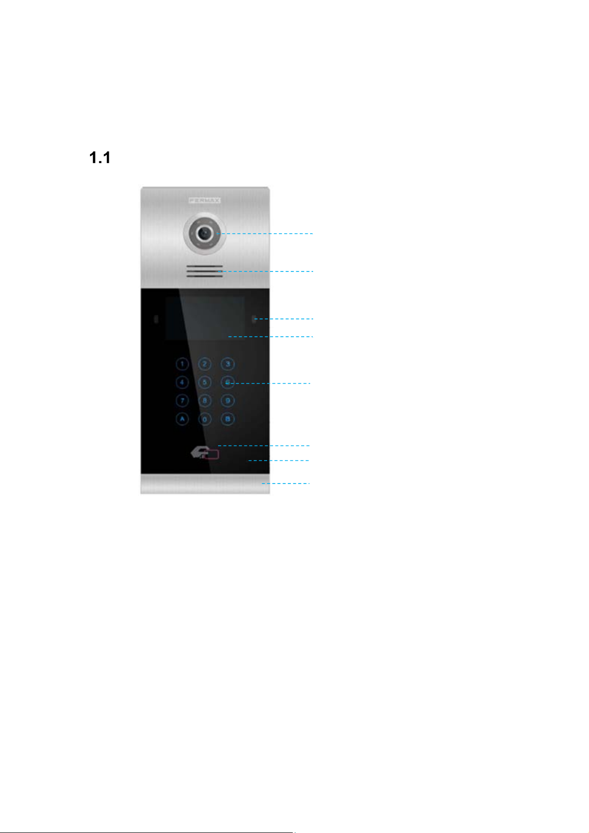
High definition camera 1,2Mpx
Lighting for night vision with LEDs
Speaker
Motion sensor
4.3” TFT
Digital keyboard (capacitive or
mechanical)
Mifare reader
Microphone
Slider
Page 4
Page 5
Panel Display Screen
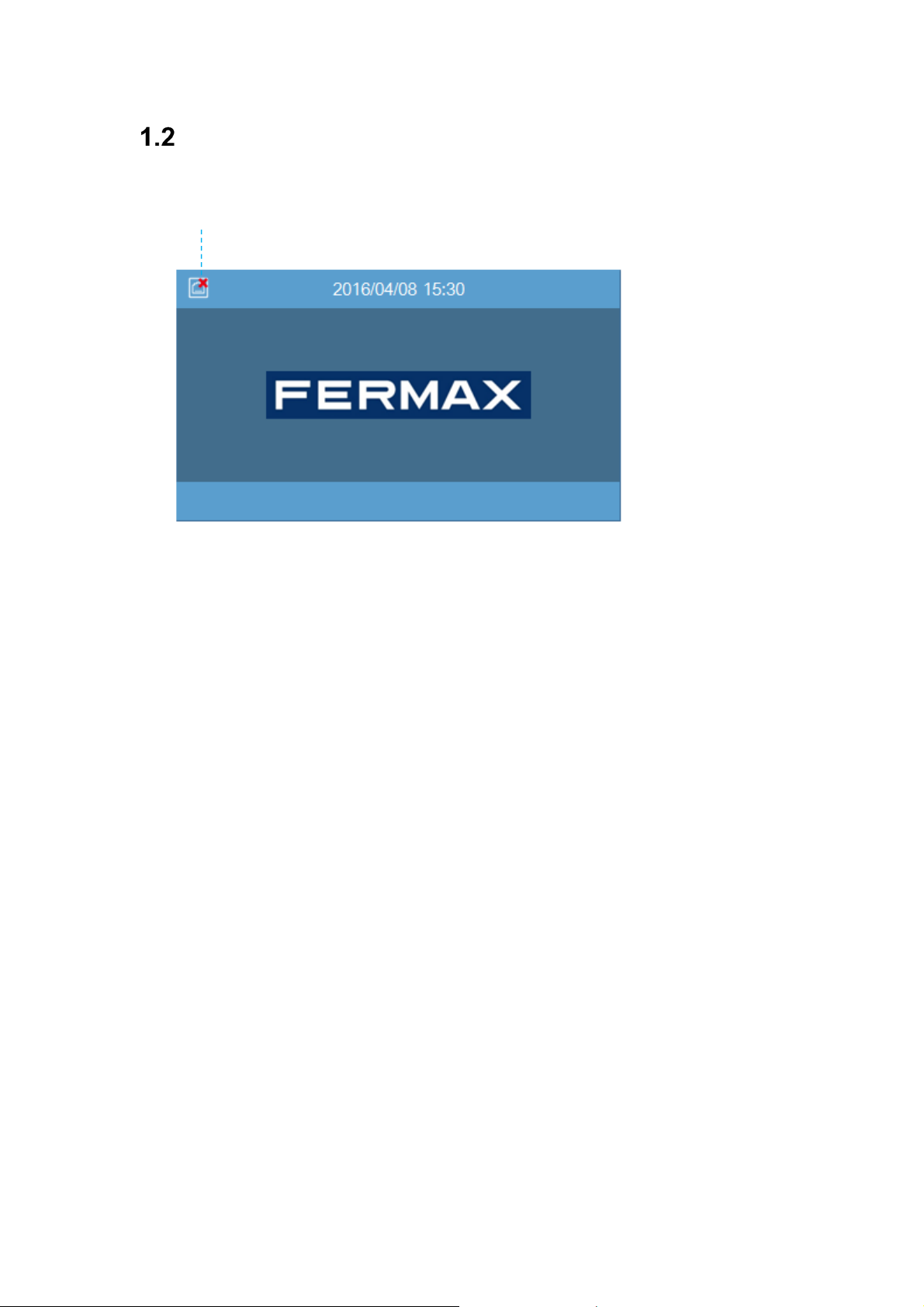
Network Status
2 Functions Introduction
Call apartment
Call guard unit
Call volume settings
Door opening, relay delay settings
Connect exit button
Speech
Door opened and tamper alarm
Lift control (Only when installed)
PIN Access Code
Mifare reader
Alarm management by access control
Face Recognition for release lock
Page 5
Page 6
Call Apartment
2.1.1 Block Panel call apartment
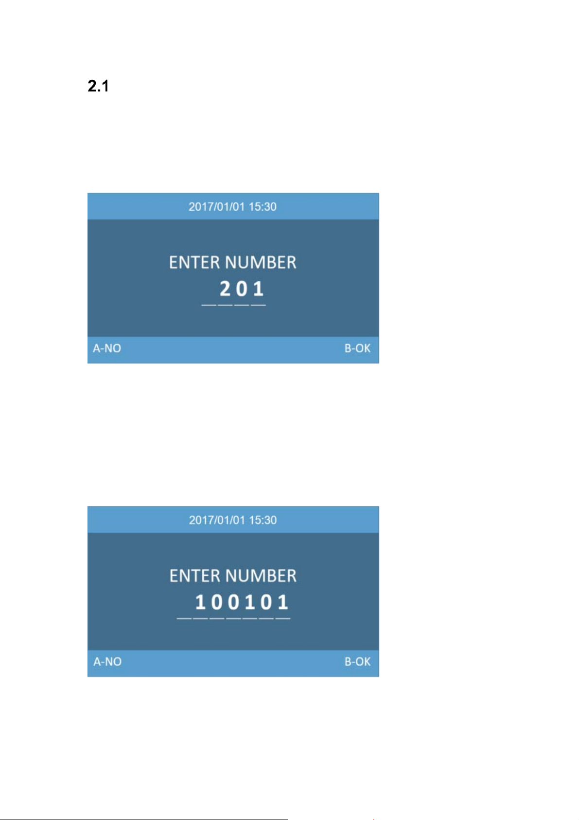
Visitors need to enter apartment number followed by B to confirm. For example, if the resident
lives in apartment 201, the visitor should enter: 201 and press B.
2.1.2 General Entry Panel call apartment
Visitors need to enter block number followed by a 4 digits apartment number followed by B to
confirm. For example, if the resident lives in block 10 apartment 101, the visitor shall enter:
10 0101 and press B.
Page 6
Page 7
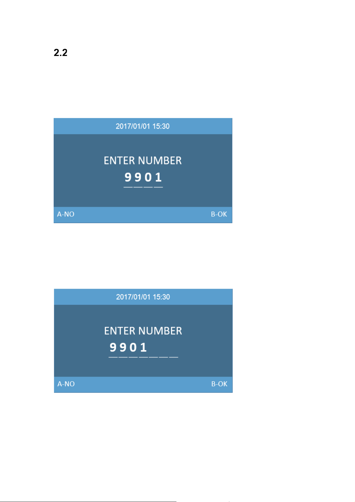
Call Guard Unit
2.2.1 Block Panel Call Guard Unit
The visitor or resident can call the guard unit by entering the number 9901 followed by B to
confirm. This call can be made from all Block Entry Panels.
2.2.1 General Entry Panel Call Guard Unit
The visitor or resident need can call the main guard unit by entering the number 9901 follo wed
by B to confirm. This call can be made from all General Entry Panels.
Page 7
Page 8
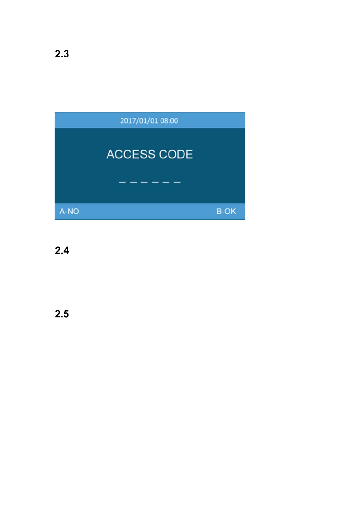
Access Code
Press key “A0” to access PIN code fun ction, entering the access code followed by B to confirm.
If the access code is correct the door will open and release the lock.
You can enable or disable the function at web of the panel.
The access code to be defined at web of the panel, Maximum access code length 6 digits.
Face Recognition
Press key “A” two times to access face recognition function, the camera of the panel will start
to read the face information. If the face data is authorized, the door will open and release the
lock. The face data is to be added through the management software. Maximum face data 6000.
Mifare Reader
Resident can access to their corresponding entrance by passing their authorized Mifare card,
the door will open and release the lock.
The Mifare card data is to be added through management software, Maximum 100,000 Mifare
cards.
Page 8
Page 9
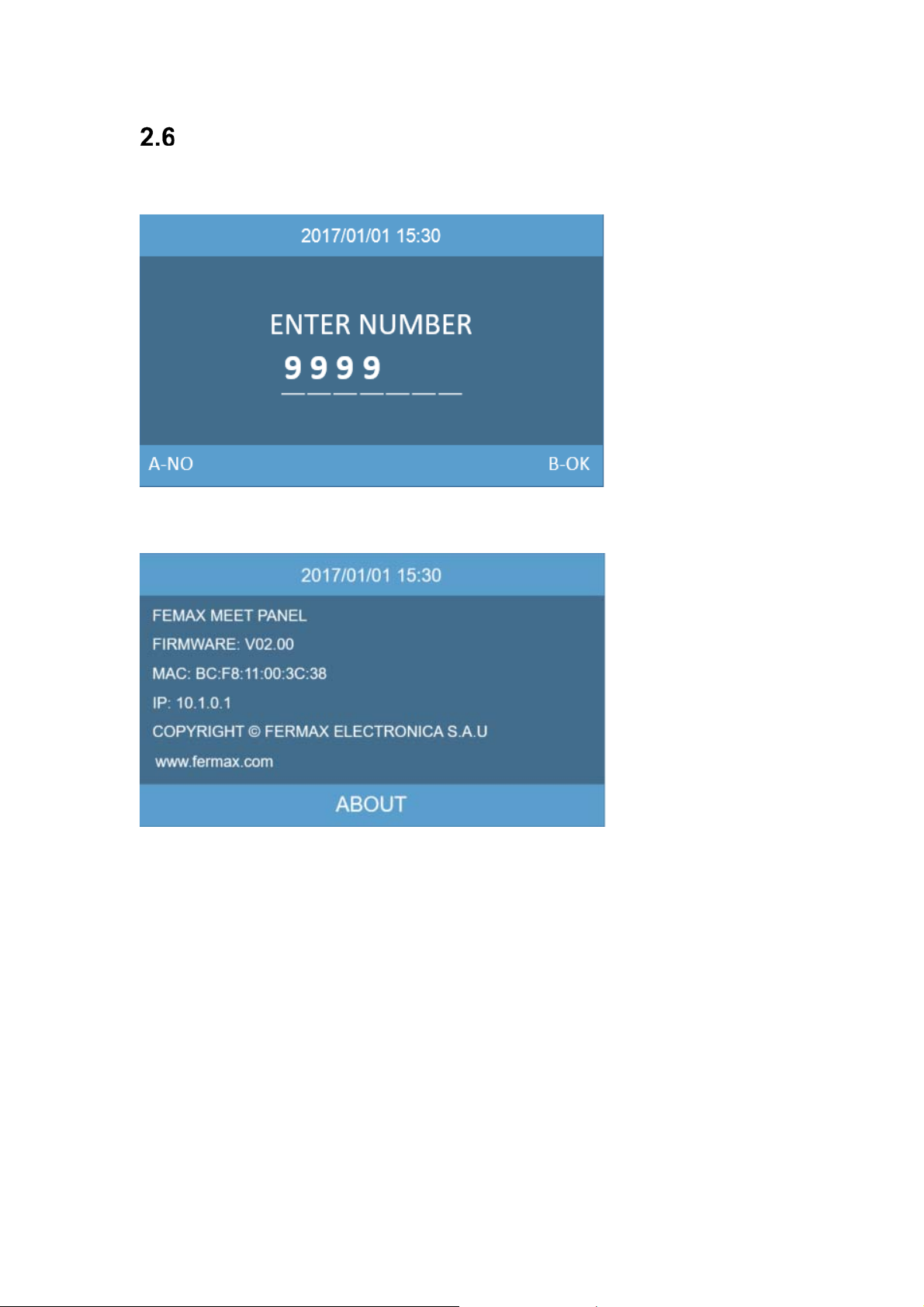
About
Enter code 9999 followed by B to confirm, The ABOUT information will show.
You can get information about the device name, firmware version, IP address, MAC address.
Page 9
Page 10
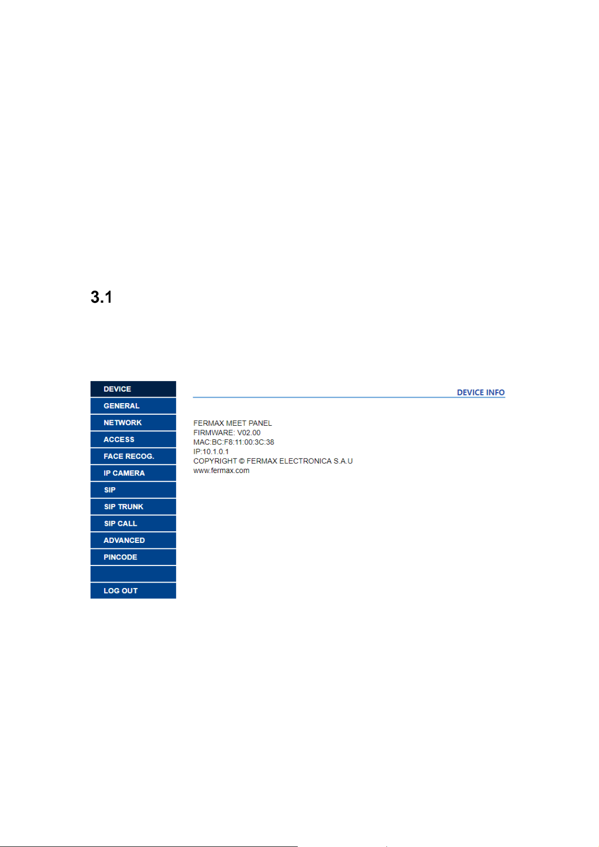
3 Configuration via Web Server
The panel has an integrated web server, which allows to configure the parameters. This web
server is accessed via the panel’s IP address.
The browser opens with the configured IP address of the panel. A screen opens requesting a
username and password
Default IP: 10.1.0.1
Username: admin
Password: 123456
Device Information
The following information is displayed: the device name, firmware version, MAC address, IP
address.
Page 10
Page 11

General Settings
Configures the panel type: General entrance panel or block panel.
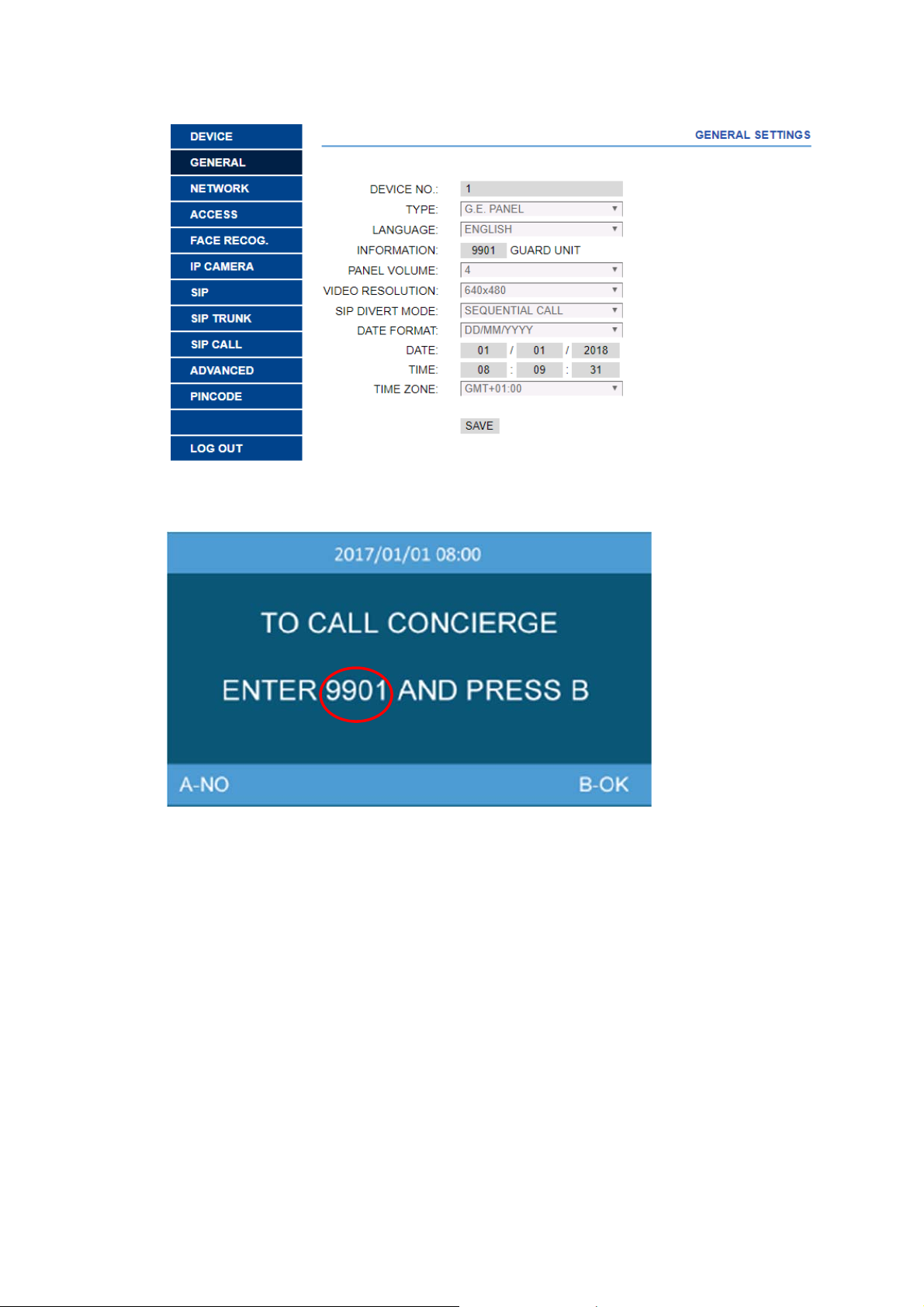
3.2.1 General Entrance Panel
DEVICE NO.: General entrance panel number, between 1 and 9000.
TYPE: For General Entrance select G.E.PANEL. The panel can communicate with all devices
of the installation.
LANGUAGE: select the desired language in the dropdown options. (default option ENGLISH).
Refresh the webpage after change the language.
INFORMA TION: 9901 GUARD UNIT , Prompt information to be di splayed on the panel, between
9901-9998, default option 9901. It is possible to modify the number according to the Guard Unit
that each panel will call.
PANEL VOLUME: Select the desired value between 1 and 6, default option 4.
The conversation volume is common for uplink and downlink.
VIDEO RESOLUTION: In order to fit the different types of monitor. The default value 640×480
is to be used usually.
SIP DIVERT MODE: (this feature may not be available at the time of releasing the manual)
PARALLEL CALL: When the panel calls the resident, the monitor and the call divert APP ring
at the same time. Once one terminal answers the call the other one stops ringing.
SEQUENTIAL CALL: When the panel calls the resident, the monitor will ring about 30s if no
answer, the call divert APP will start to ring
DA TE FORMAT: Date format.
DA TE: Setting the date of panel.
TIME: Setting the time of panel.
TIME ZONE: Setting the time zone of panel.
Select local time zone and save.
If the project has no management software the installer can set date, time and time zone
manually . If the project has management software, the date and time of panel will synchronizes
automatically with the management software. If the panel has access to internet, the date and
time of panel will also synchronize with internet time server.
NOTE:
Do not use TIME ZONE setting if panel is connected to Internet or Management Software.
Date and time can’t be saved after power loss, the time zone and date format can be saved.
Page 11
Page 12
Page 12
Page 13

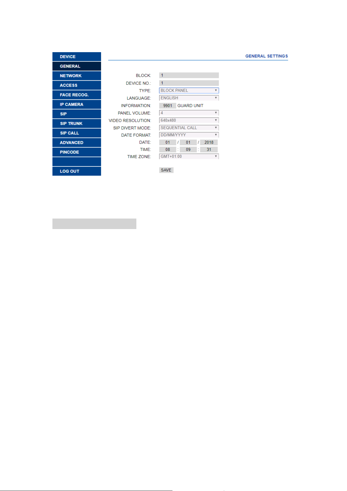
3.2.2 Block Panel
BLOCK: Block number, between 001 and 999 (default option 1).
DEVICE NO.: Panel Number, between:01-99 (default option 1).
TYPE: For block entrance, choose BLOCK PANEL. The panel can communicate with all
devices on the same block.
LANGUAGE: Select the desired language for the drop-down options. (default option ENGLISH).
Refresh the webpage after change the language.
INFORMA TION: 9901 GUARD UNIT , Prompt information to be di splayed on the panel, between
9901-9998, default option 9901. It is possible to modify the number according to the Guard Unit
that each panel will call.
PANEL VOLUME: Select the desired value between 1 and 6, (def ault option 4).
The conversation volume is common for uplink and downlink.
VIDEO RESOLUTION: In order to fit the different type of Monitor, The default values 640×480
is be used usually.
SIP DIVERT MODE: (this feature may not be available at the time of releasing the manual)
PARALLEL CALL: When the panel calls the resident, the monitor and the call divert APP ring
at the same time. Once one terminal answers the call the other one stops ringing.
SEQUENTIAL CALL: When the panel calls the resident, the monitor will ring about 30s if no
answer, the call divert APP will start to ring
DA TE FORMAT: Date format.
DA TE: Setting the date of the panel.
TIME: Setting the time of the panel.
TIME ZONE: Setting the time zone of the panel.
Select local time zone and save.
If the project has no management software the installer can set date, time and time zone
manually . If the project has management software, the date and time of panel will synchronizes
automatically with the management software. If the panel has access to internet, the date and
time of panel will also synchronize with internet time server.
Page 13
Page 14
NOTE:
Do not use TIME ZONE setting if panel is connected to Internet or Management Software.
Date and time can’t be saved after power loss, the time zone and date format can be saved.
Page 14
Page 15
Network Settings
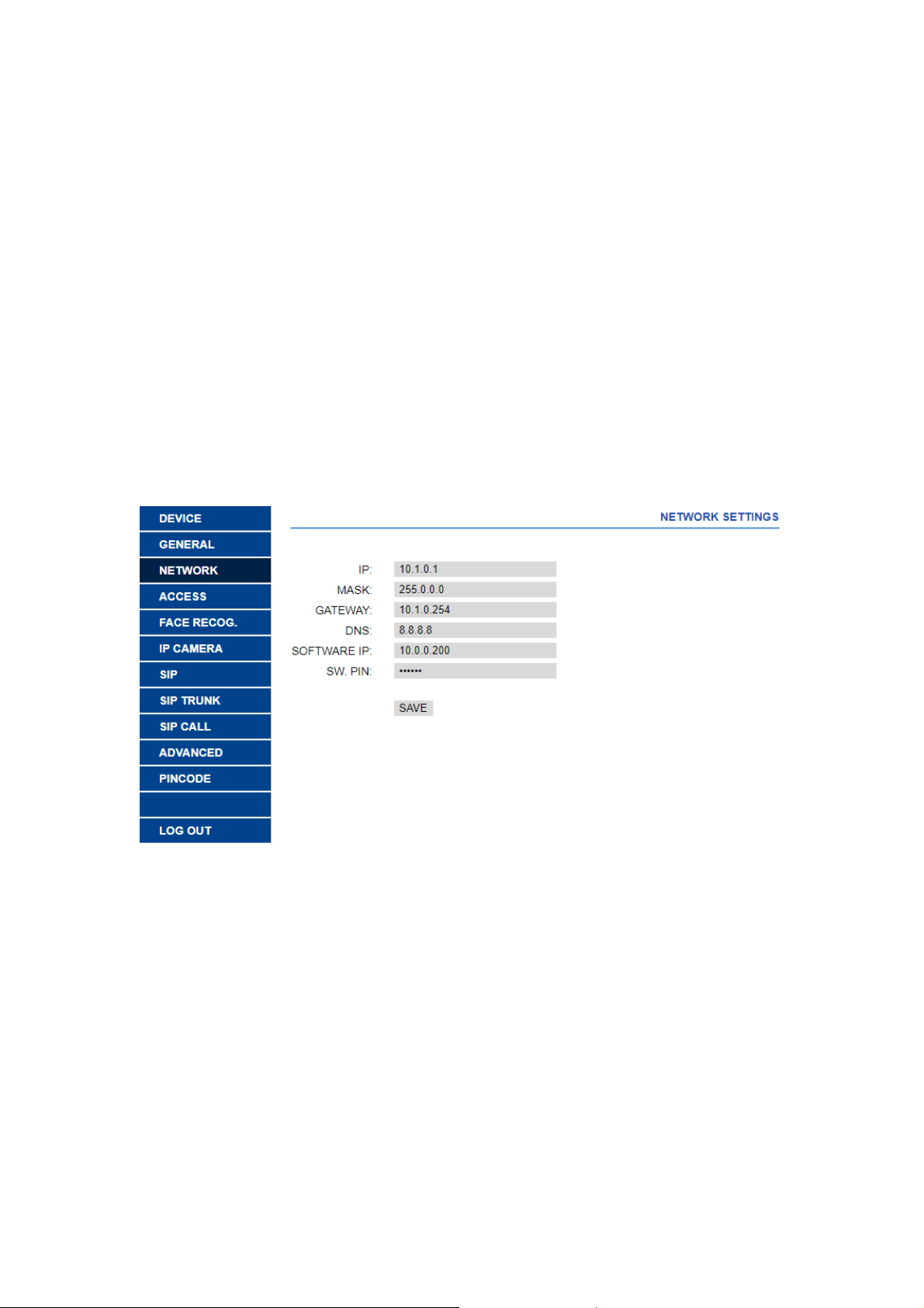
MEET allows the installer to define the IP range according to the project needs and make the
network management easier. MEET panel network mode is static mode. Ensure that each
device has a unique IP address in same installation. The devices (digital panel, monitor and
guard unit) will show IP conflict if there same IP is us ed on the same LAN.
IP: IP address of the panel (default option 10.1.0.1).
MASK: Subnet mask of the panel (default option 255.0.0.0).
GATEWAY: Default gateway of the panel (default option 10.254.0.1).
DNS: DNS of the panel (default option 8.8.8.8).
SOFTWARE IP: IP address of PC where MEET management software is installed.
(default option 10.0.0.200).
SW. PIN: The pin code is to be used when the panel is registered in MEET management
software.
Page 15
Page 16
Access
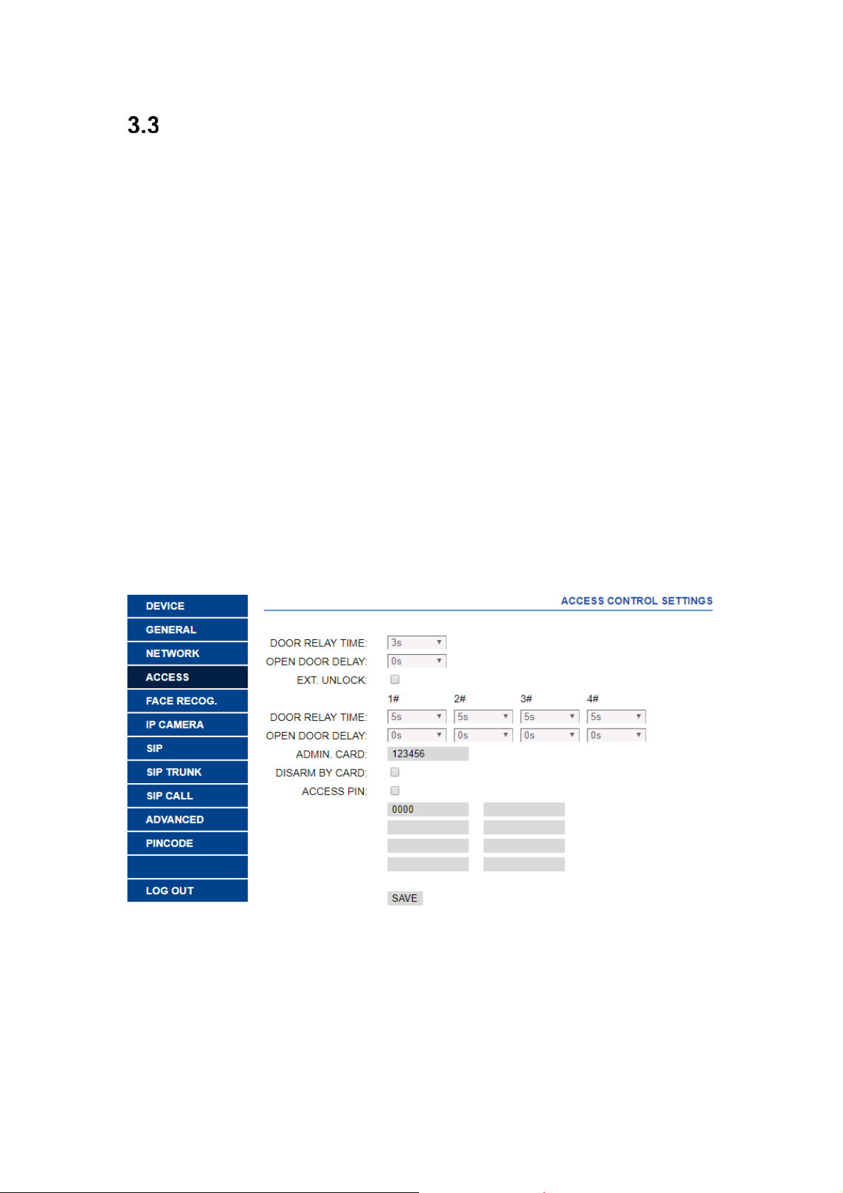
DOOR RELAY TIME: Time for lock-release relay remains active (1-9s optional).
OPEN DOOR DELAY: The time when the unlocked signal is sent to the start of the relay.
The delay time is useful when the lock is not close panel (0-9s optional).
EXT. UNLOCK: Enable or disabled external relay unlock function.
Relay 1-4 DOOR RELAY TIME: Time for lock-release relay remains active (1-9s optional).
Relay 1-4 OPEN DOOR DELAY: The time delay between the unlock signal sent and the relay
activation. The delay time parameter is useful when the door lock is not close to the panel (09s optional).
ADMIN CARD: Master card registered to enroll additional prox cards. When there is no
management software enter 0000 if you do not know the ID of the admin card. The first prox
card detected by the reader will act as admin/master card the card of resident can be added
afterwards. If this method is used, register the resident proximity id numbers on the cards.
DISARM BY CARD: When the card open the door, the alarm status of monitor corresponding
unit can change to HOME mode.
ACCESS PIN: Enable or disabled the activation of the relay for PIN code access.
UP to 8 different PIN codes per panel.
PIN length between 4 to 6 digits.
REMARK: Reference F01491 (4 relay module) must be connected to the RS485 port of the
panel no.1. The module address must be set to number 2.
Page 16
Page 17
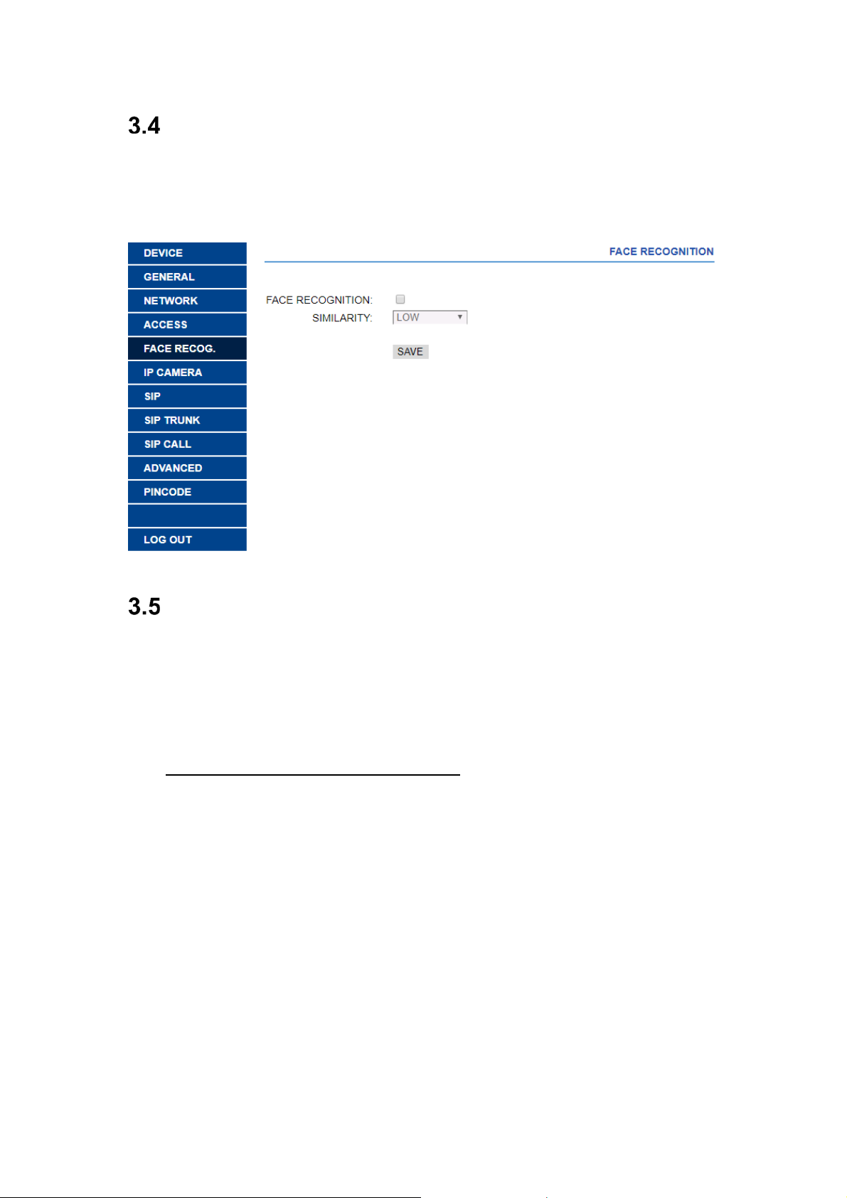
Face Recognition
FACE RECOGNITION: Enable or disabl ed face recognition function.
SIMILARITY: High, medium and low options. Default is low.
The face data must be added through MEET management software.
IP Camera
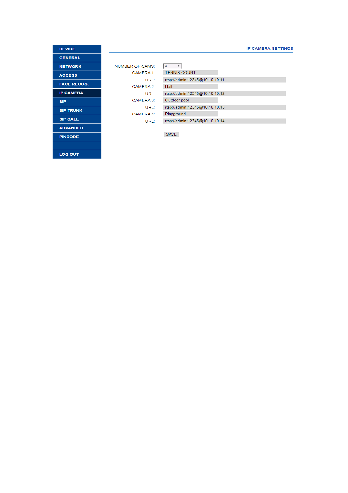
The monitor can switch to IP CCTV camera video during a conversation. This function allows
to configure IP CCTV cameras using RTSP protocol to be displayed as an auxiliary camera to
provide different view angles from the door or related areas.
NUMBER OF CAMS: IP camera Number. Up to 4 different cameras.
CAMERA 1: IP camera name.
URL: rtsp://user:password@ip address of ip camera.
user:password: for cameras that require a username and password for connection. These
fields are optional and depends on the RTSP stream of each IP camera.
Page 17
Page 18
Page 18
Page 19
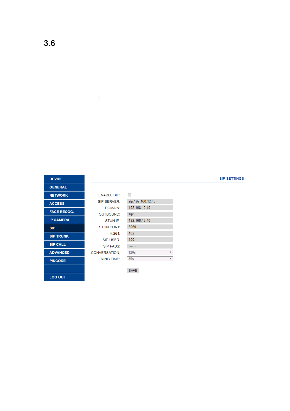
SIP Settings
ENABLE SIP: Enable or disable sip function.
SIP SERVER: SIP server IP address.
DOMAIN: Sip server domain.
OUTBOUND: Some servers are used when NAT is active on the router.
STUN IP: Audio and video NAT traversing public network server IP.
STUN PORT: The port of audio and video NAT traversing public network server.
H.264: Video coding parameters.
SIP USER: The username of sip account.
SIP PASS: The password of sip account.
CONVERSATION: Conversation duration, 120s, 300s, 600s, 1200s and 1800s optional.
RING TIME: Ring time, 35s, 45s, 60s, 90s and 120s optional.
REMARK: When the panel is used as a sip device, use quick dial to call SIP devices or receiv e
calls from other SIP devices. SIP function has to be enabled.
Page 19
Page 20
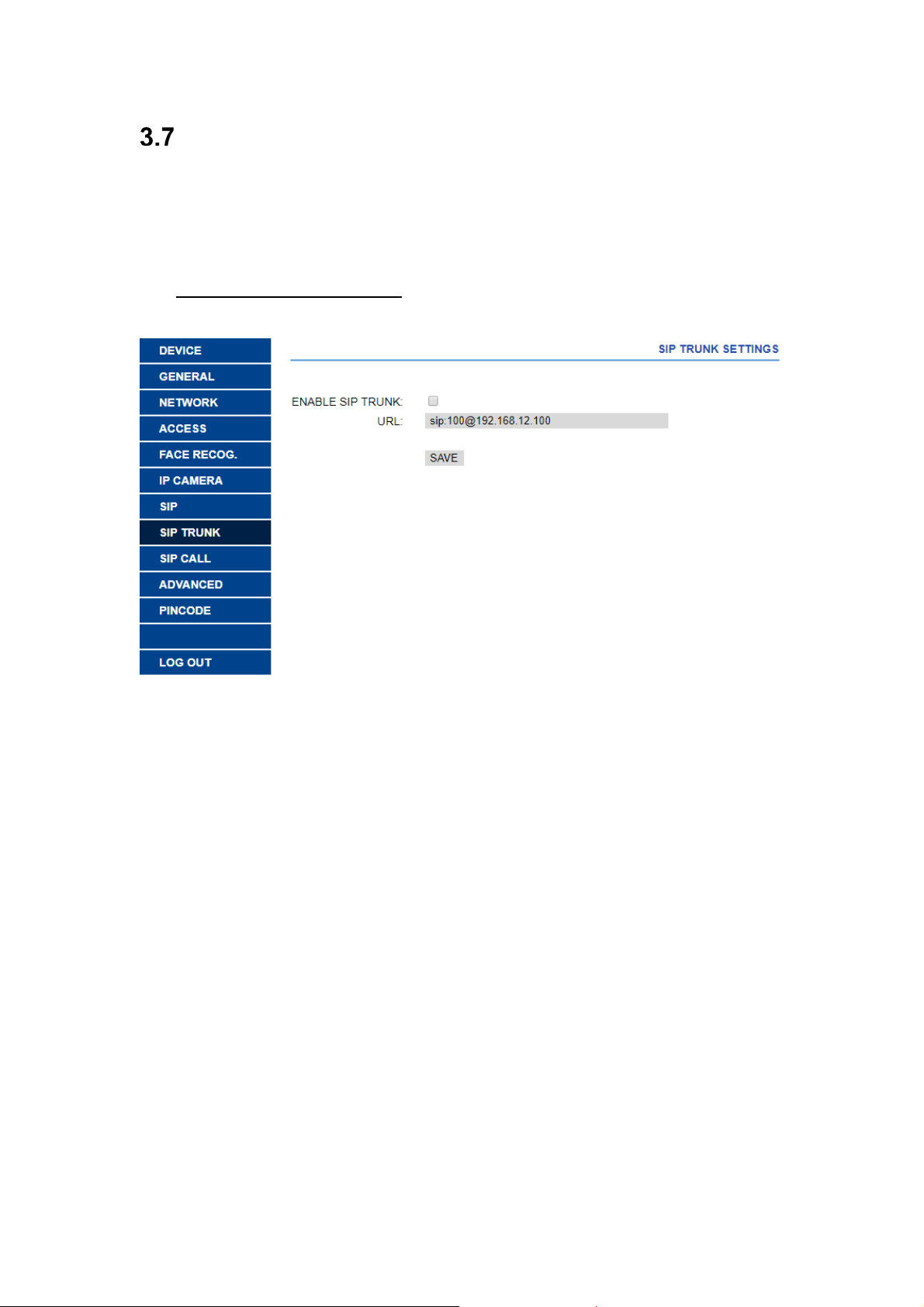
SIP Trunk
When there is a VoIP gateway installed on the system or a sip server has a PSTN line.
The panel call can be diverted to user's mobile phone or land line telephone through a voice
gateway.
ENABLE SIP TRUNK: Enable or disable SIP trunk function.
URL: sip: sip account @ wan IP: 5062
Page 20
Page 21
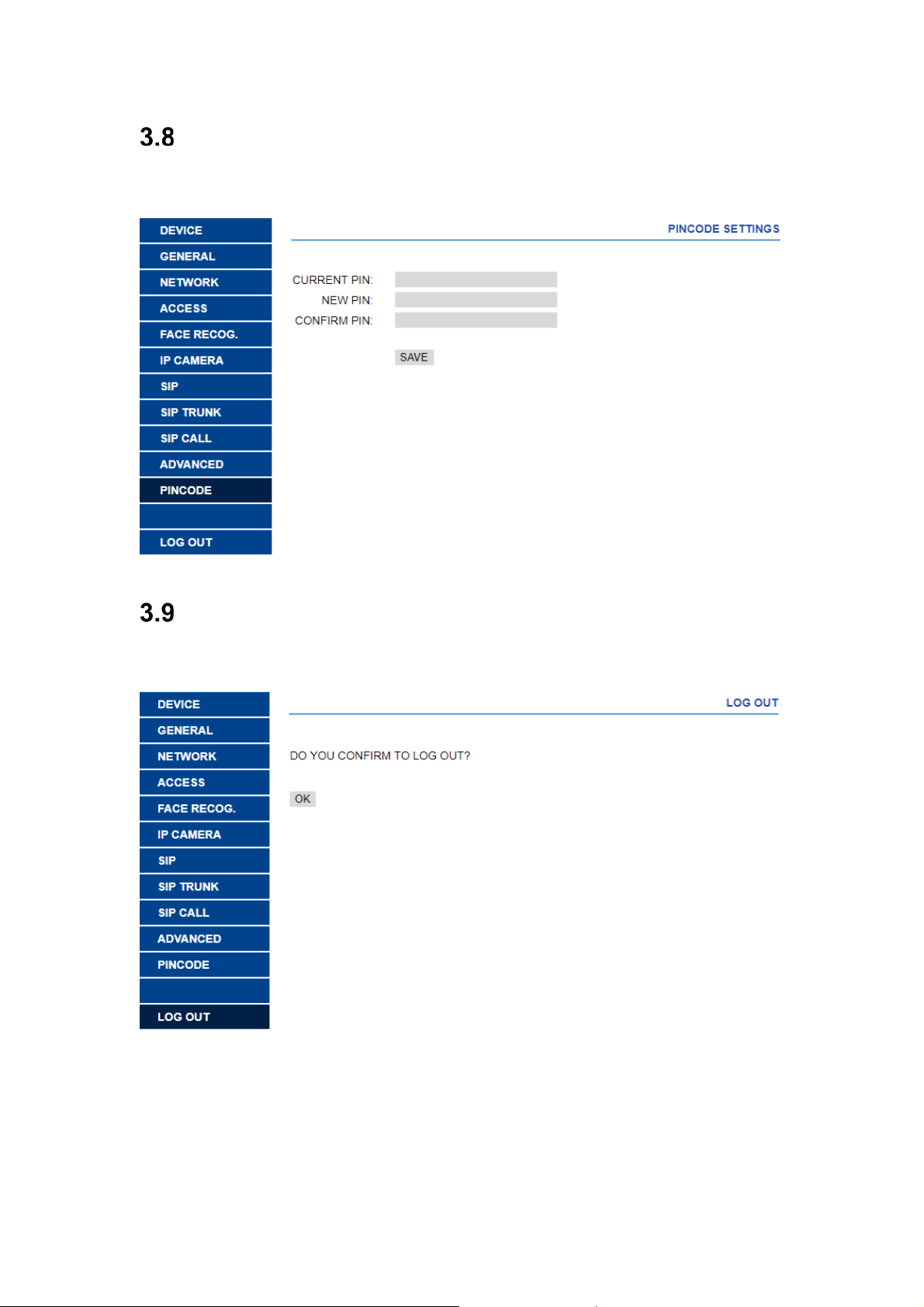
Pincode Settings
This allows to change the pin code of the web server login.
Logout
Log out the web server.
Page 21
Page 22
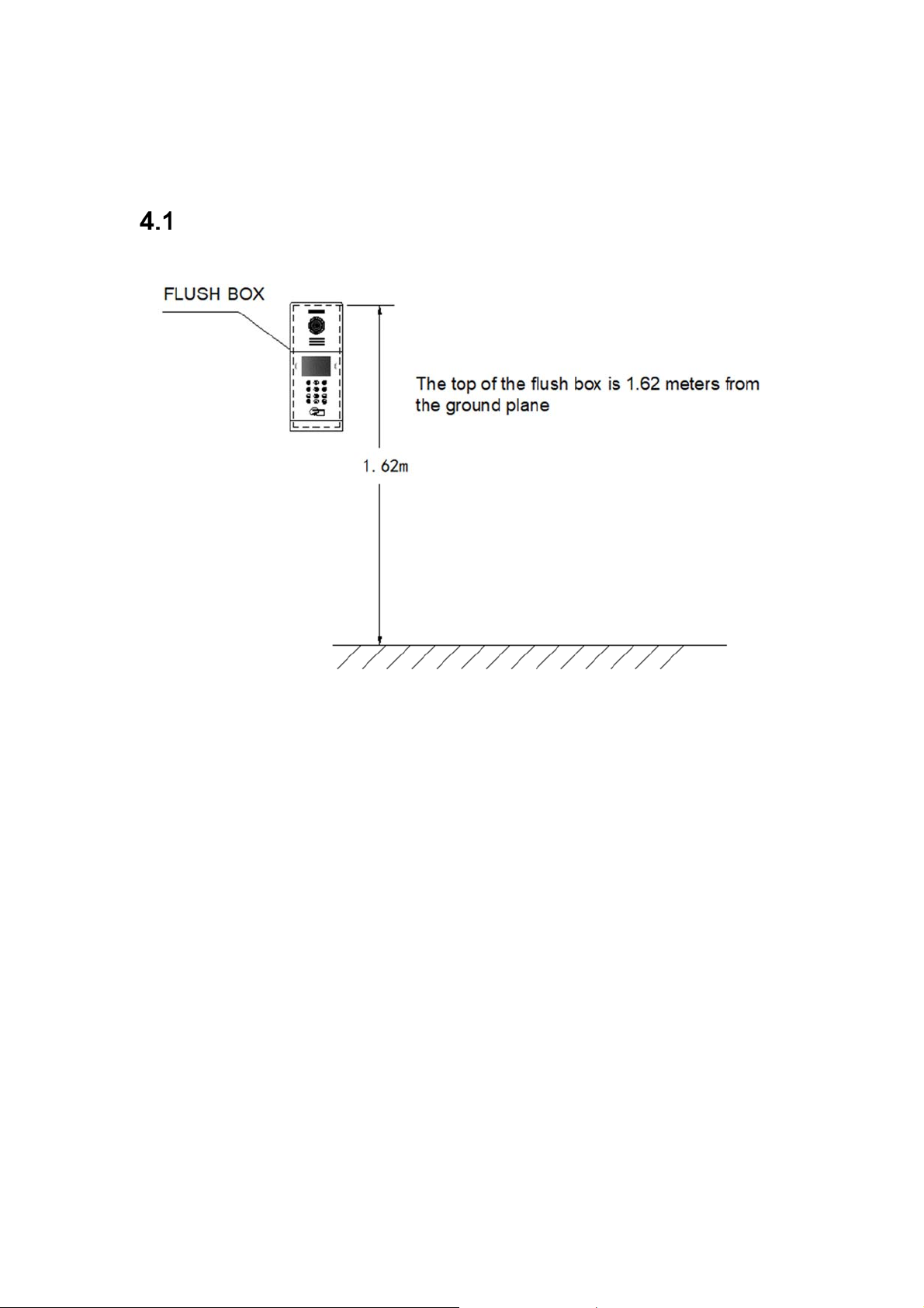
4 Installation
Installation height
Page 22
Page 23
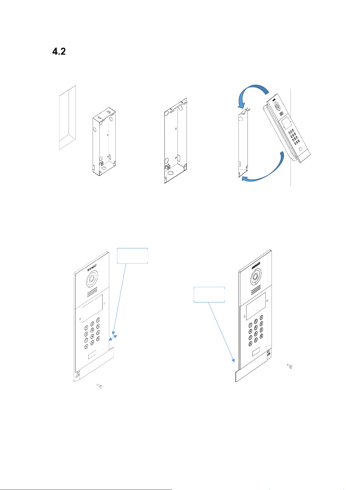
Installation Step Diagram
,1 Flush box ○,2Base flush box depth adjustment hook.
○
2.2CM
2.2CM
,3The upper part of the panel is
○
stuck in, then move the panel to
the flush box.
,4Move the slider of the panel and fix the two screws. When installing, pay attention
○
to the reservation of the 2.2CM space around the door to move the slide cover.
Page 23
Page 24
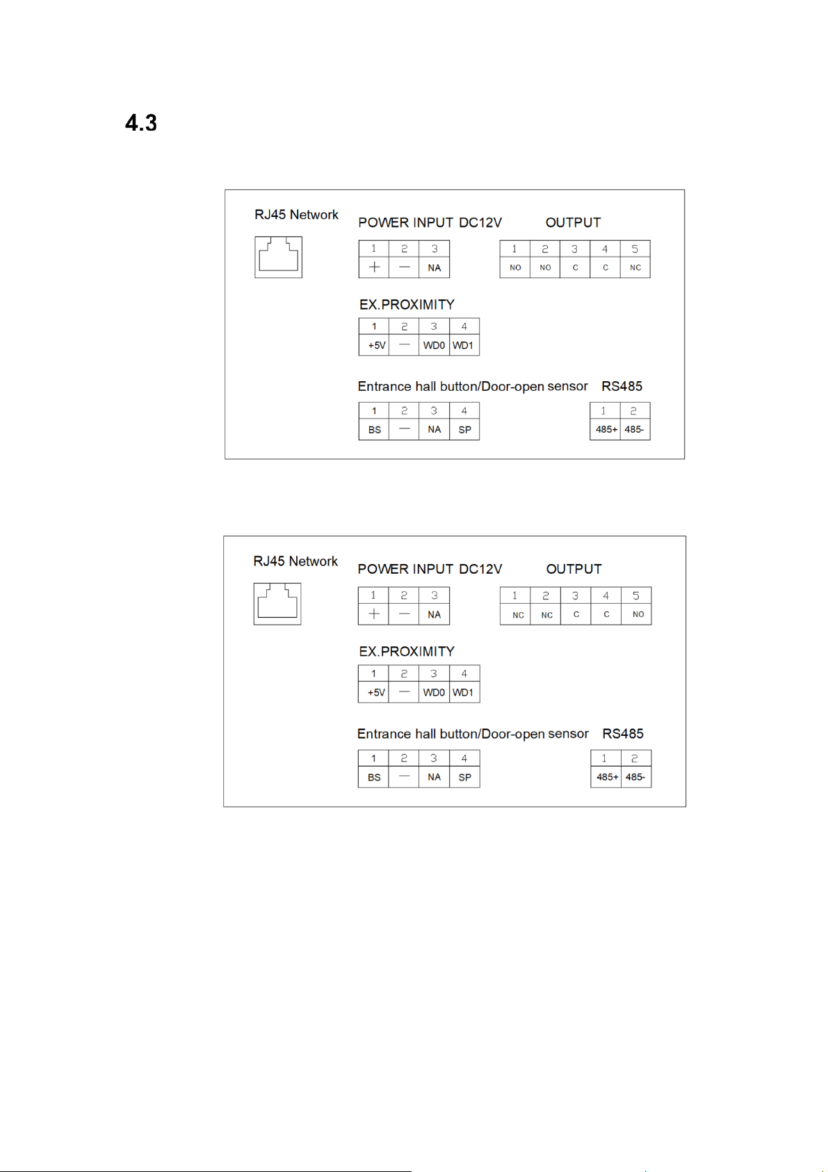
Connectors
PANELS WITH HW 95770/95771
PANELS WITH HW 95770B/95771B
10/100Mbps RJ45 Port.
+, —: 12Vdc Power Input.
C, NO, NC:
+5V, —, WD0, WD1: Wigand-26 protocol output or input.
BS, —:
—, SP:
485+, 485-: To lift control gateway, F01491 (4 relay module).
Relay contacts for release lock, the double terminals are the same connection.
Exit button.
Door-open sensor.
Page 24
Page 25

Technical Parameters
Dimensions
Panel (mm): 154(W) ×379(H) ×50(D)
Flush box (mm): 142(W) ×357(H) ×58(D)
Power supply: 12Vdc
Standby current: 250mA
Working current: 500mA
Technical specifications of the display:
-Size: 4.3 inch
-Format: 4:3
-Resolution: 480*272
Camera pixel: 1.2 megapixels
o
visual angle: Vertical 72º, Horizontal 54º
90
Minimum illumination: 0.5Lux
Maximum conversation time: 120s
Door relay time: 1-9s
Door delay time: 0-9s
Door sensor time: 120s
IC cards: 100,000
Face data: 6000
Operating temperature: -10~70℃
Relative humidity: 20%~80%, without condensation
Page 25
 Loading...