

Page 1

MDS
MDS
MDSMDS
MDSMDS
MDS
MDS
MDSMDS
MDSMDS
TECHNICAL MANUTECHNICAL MANU
TECHNICAL MANUTECHNICAL MANU
TECHNICAL MANU
TECHNICAL MANU
TECHNICAL MANUTECHNICAL MANU
TECHNICAL MANUTECHNICAL MANU
SECTION III - EQUIPMENT COMMON TO MDS
DIGITAL, DIRECT and CITY SYSTEMS
ALAL
ALAL
AL
AL
ALAL
ALAL
Page 1
Page 2

MDS
MDS
MDS TECHNICAL MANUAL
The MDS technical manual is comprised of the following sections:
- MDS Systems Introduction (Code. 94726Ib-0)
- Section I: MDS Digital System (Code. 94726Ib-1)
- Section II: MDS Direct and MDS City System (Code. 94726Ib-2)
- Section III: Equipment common to MDS Digital, Direct and City Systems (Code. 94726Ib-3)
- Section IV: Installation Diagrams (Code. 94726Ib-4)
MDS Technical Manual - Section III
Code 94726Ib-3 V04_08
This technical document of an informative nature is published by FERMAX ELECTRONICA S.A.E., who reserve the right to
modify characteristics of the products referred to herein at any time and without prior notice. These changes will be reflected
in subsequent editions of this document.
Page 2
Page 3

MDS
MDS
TABLE OF CONTENTS
SECTION III - EQUIPMENT COMMON TO MDS DIGITAL, DIRECT and CITY SYSTEMS
RESIDENTIAL TERMINALS .......................................................................................................................................5
- Monitors ................................................................................................................................................................. 5
- Loft ................................................................................................................................................................................. 7
- Citymax .......................................................................................................................................................................... 9
- Sailing .......................................................................................................................................................................... 11
- Olympo ......................................................................................................................................................................... 13
- Telephones ........................................................................................................................................................... 15
- Citymax ........................................................................................................................................................................ 15
EQUIPMENT COMMON TO THE MDS DIGITAL, DIRECT AND CITY SYSTEMS. .................................................... 17
- Power Supplies ....................................................................................................................................................18
- Emergency Modules ............................................................................................................................................ 18
- MDS Repeater. ....................................................................................................................................................19
- Video Amplifier ..................................................................................................................................................... 19
- Electrical Door-Opener ......................................................................................................................................... 19
- Fermax Cables and Distance Panels ...................................................................................................................20
- Decoder Programming Module .............................................................................................................................22
Page 3
Page 4

MDS
MDS
Equipment common to MDS Digital, Direct and City Systems
- Residential Terminals
· Monitors
Loft
Citymax
Sailing
Olympo
Telephones:
Citymax
- Equipment common to MDS Digital, Direct and City Systems
· Power Supplies and Emergency Modules
. MDS Repeater (Ref. 2239)
· Video Amplifier (Ref. 4110)
· Door-Opener
· Cables and Distance Panels
· Decoder Programming Module (Ref. 2466)
Page 4
Page 5

MDS
MDS
RESIDENTIAL TERMINALS
Monitors and Telephones
Page 5
Page 6

MDS
MDS
Page 6
Page 7
MDS
90º
MDS
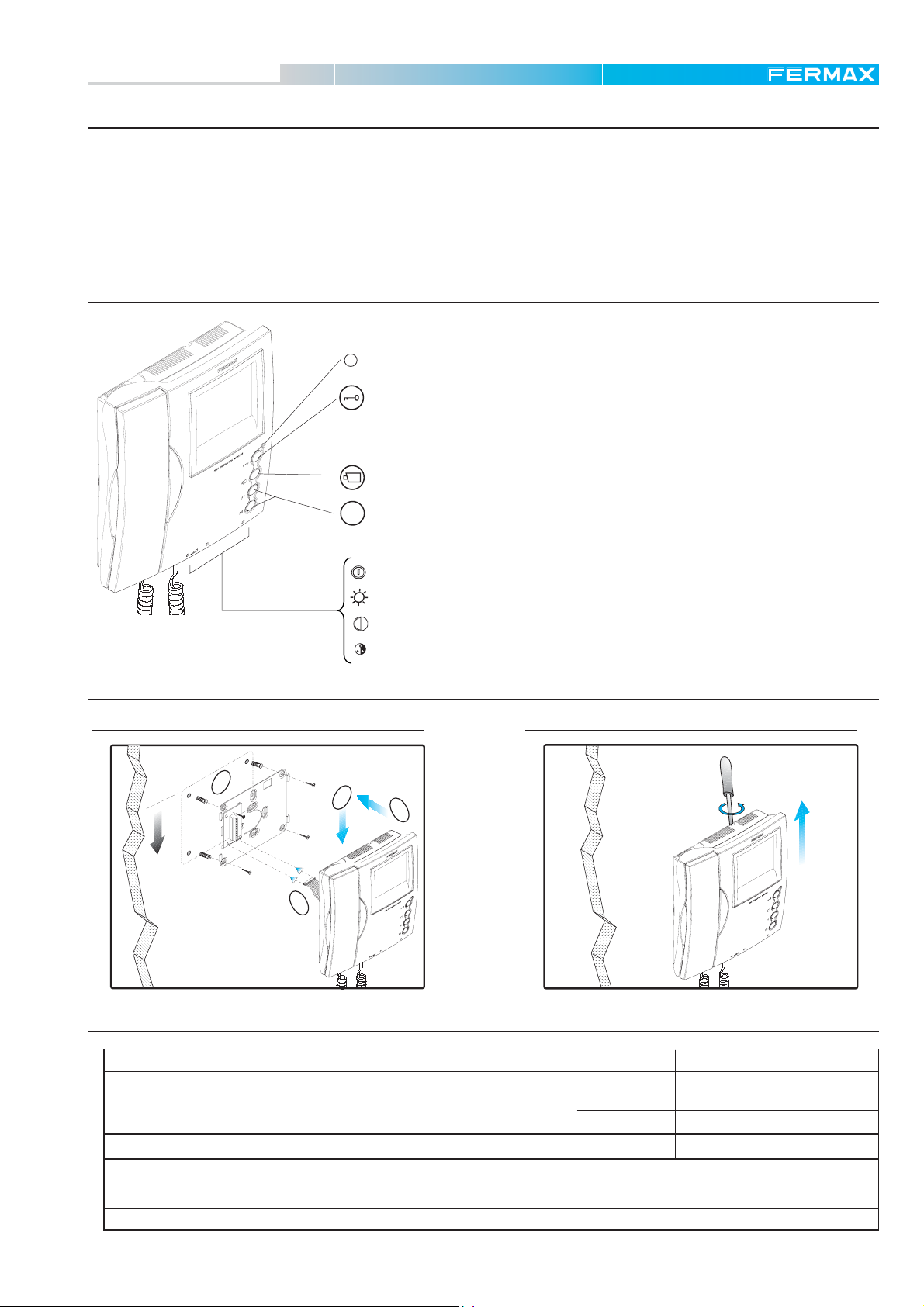
4+N LOFT Monitors
The monitors used in the MDS video door entry systems are conventional monitors which do not require programming
and are connected to the corresponding audio decoder output. The decoder is the part which establishes communication
between the Panel or Guard Unit and the residential monitor called.
The Loft monitor for MDS (in the same way as for 4+N) is available in colour and B/W and can be combined with other
Fermax monitor and telephone models, in the same system.
Control Descriptions
Monitor Led Indicator On.
Door-Opener/ Call Guard.
· When you are communicating with the Outdoor Panel, pressing this button will activate the door-
opener.
· When you press this button with the telephone on the hook, a call will be made to the guard
(where one exists).
Not operational in MDS systems.
F1 and F2: Buttons for additional functions (panic buttons...).
F
Installing the Monitor
1
1.60m
On/Off (three positions: Off - Average Volume On - High Volume On).
Brightness
Contrast
Colour (only in colour monitor).
DisassemblyAssembly
4
3
2
Technical Characteristics
Power Supply
Consumption
Operating Temperature - Humidity
Image Tube
Video Signal: Composite Signal 1 Vpp 75 Ω, 7 Mhz.
Dimensions (Height x Width x Depth): 221x203x61 (mm)
. B/W: Flat Screen. 4" Diagonal (100 mm) Colour: TFT4”
on standby
audio + video
18 Vdc
B/W:
12 mA
650 mA
[5 , +60 °C] - [0,90%]
Colour.
8 mA
400 mA
Page 7
Page 8

MDS
MDS
Operation of the Loft Monitor
Call
* When the call button is pressed on the Outdoor Panel a call tone is emitted both on the
outdoor panel and the monitor, switching on the monitor and switching off the ON-OFF indicators.
If there is additional equipment in the residence, this will also sound. If the call is not answered
the image on the monitor will disappear after 90 seconds.
Answering a call
* On picking up the telephone receiver you can communicate with the visitor.
The duration of the communication is limited to the conversation time programmed for the
MDS Direct and City Panels or the MDS Central Unit.
Open the door for the visitor
* While communicating with the visitor you can open the door by pressing the button
Call Guard Unit
* With the monitor on standby, when you press this button
unit (where one exists).
a call will be made to the guard
.
Page 8
Page 9

MDS
MDS
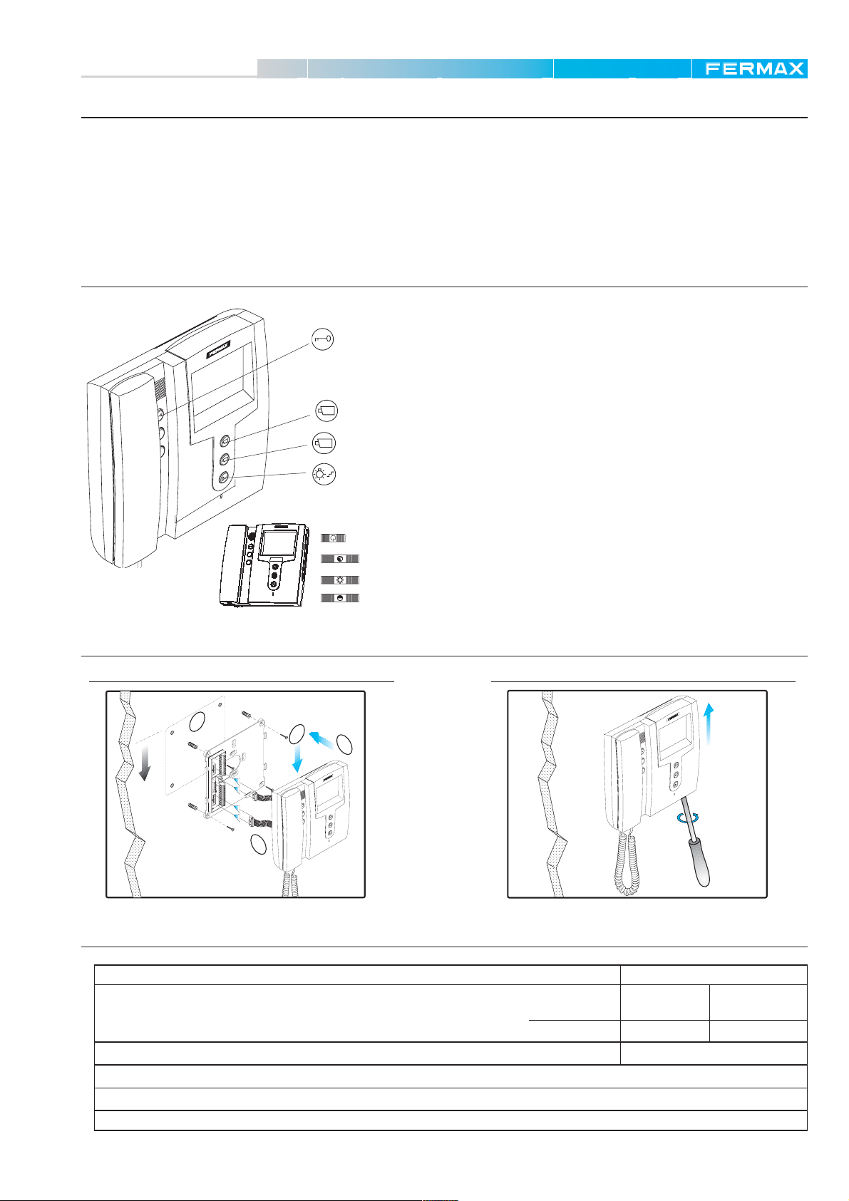
4+N CITYMAX Monitors
The monitors used in the MDS video door entry systems are conventional monitors which do not require programming
and are connected to the corresponding audio decoder output. The decoder is the part which establishes communication
between the Panel or Guard Unit and the residential monitor called.
There are different versions of the Citymax monitor for MDS (in the same way as for 4+N) based on the number of
auxiliary buttons on the monitor: Basic (no additional button), Extra (2 additional buttons) and Complet (5 additional
buttons). All the versions are in colour and B/W.
If you require a Panic Button you will need to use an Extra or Complet monitor with an extended connector.
It can be combined with other Fermax monitor and telephone models in the same system.
Control Descriptions
Door-opener / Call to Guard.
· When you are communicating with the Outdoor Panel, pressing this button will activate the door-
opener.
N
IO
LUT
ESO
R
H
NITOR
IG
H
T MO
FLA
· When you press this button with the telephone on the hook, a call will be made to the guard
(where one exists).
1
Not operational in MDS systems.
2
Not operational in MDS systems.
Installing the Monitor
1
1.60m
Colour Adjustments (on colour monitor)
Stairway Light Relay (on B/W monitor)
Buttons for additional functions on EXTRA models (2 additional buttons) and
COMPLET (5 additional buttons).
ON/OFF Switch - Monitor Led Indicator On
Brightness
Contrast
DisassemblyAssembly
4
3
N
O
I
T
U
L
O
S
R
E
O
R
IT
H
N
G
I
O
H
M
T
1
A
L
F
2
N
O
I
T
U
L
O
S
R
E
O
R
IT
H
N
IG
O
H
M
T
1
A
L
F
2
90º
2
Technical Characteristics
Power Supply
Consumption
Operating Temperature - Humidity
Image Tube
Video Signal: Composite Signal 1 Vpp 75 Ω, 7 Mhz.
Dimensions (Height x Width x Depth): 195x211x60 (mm)
. B/W: Flat Screen. 4" Diagonal (100 mm) Colour: TFT4”
on standby
audio + video
18 Vdc
B/W:
15 mA
350 mA
Colour.
15 mA
350 mA
[5 , +60 °C] - [0,90%]
Page 9
Page 10

MDS
MDS
Operation of the Citymax Monitor
Call
* When the call button is pressed on the Outdoor Panel a call tone is emitted both on the
N
O
I
T
U
L
O
S
R
E
O
R
T
I
H
N
G
I
O
H
M
T
1
A
L
F
2
N
O
I
T
U
L
O
S
R
E
O
R
T
I
H
N
G
I
O
H
M
T
1
A
L
F
2
outdoor panel and the monitor, switching on the monitor and switching off the ON-OFF indicators.
If there is additional equipment in the residence, this will also sound. If the call is not answered
the image on the monitor will disappear after 90 seconds.
Answering a call
* On picking up the telephone receiver you can communicate with the visitor.
The duration of the communication is limited to the conversation time programmed for the
MDS Direct and City Panels or the MDS Central Unit.
Open the door for the visitor
* While communicating with the visitor you can open the door by pressing the button
N
IO
T
U
L
O
S
R
E
O
R
IT
H
N
IG
O
H
M
T
1
A
L
F
2
.
Call Guard Unit
* With the monitor on standby, when you press this button
a call will be made to the
guard unit (where one exists).
Page 10
Page 11
MDS
MDS
4+N Sailing Monitors
The monitors used in the MDS video door entry systems are conventional monitors which do not require programming
and are connected to the corresponding audio decoder output. The decoder is the part which establishes communication
between the Panel or Guard Unit and the residential monitor called.
The Sailing monitor for MDS (in the same way as for 4+N) is available in colour and B/W and can be combined with
other Fermax monitor and telephone models, in the same system.
It does not have an additional button for a panic button function.
Control Descriptions
Door-opener / Call Guard.
· When you are communicating with the Outdoor Panel, pressing this button will activate the door-
opener.
· When you press this button with the telephone on the hook, a call will be made to the guard
(where one exists).
1
HIGH RESOLUTION
FLAT MONITOR
1
2
Not operational in MDS systems.
2
Not operational in MDS systems.
Stairway Light Relay.
Installing the Monitor
1
1.60m
2
Technical Characteristics
HIGH RESOLUTION
ON/OFF Switch - Monitor Led Indicator On
FLAT MONITOR
1
2
Colour (only in colour monitor)
Brightness
Contrast
DisassemblyAssembly
4
3
N
O
I
T
U
L
O
S
R
E
O
R
T
I
H
N
G
I
O
H
M
T
A
L
F
1
2
N
TIO
LU
SO
E
OR
R
NIT
HIGH
T MO
LA
F
1
2
90º
Power Supply
Consumption
Operating Temperature - Humidity
Image Tube
. B/W: Flat Screen. 4" Diagonal (100 mm) Colour: TFT4”
Video Signal: Composite Signal 1 Vpp 75 Ω, 7 Mhz.
Dimensions (Height x Width x Depth): 195x211x60 (mm)
on standby
audio + video
18 Vdc
B/W:
10 mA
650 mA
Colour.
10 mA
400 mA
[5 , +60 °C] - [0,90%]
Page 11
Page 12

MDS
MDS
Operation of the Sailing Monitor
Call
* When the call button is pressed on the Outddor Panel a call tone is emitted both on the
N
O
I
T
U
L
O
S
R
E
O
R
T
I
H
N
G
I
O
H
M
T
A
L
F
1
2
ION
LUT
R
ITO
H RESO
HIG
AT MON
FL
1
2
outdoor panel and the monitor, switching on the monitor and switching off the ON-OFF
indicators.
If there is additional equipment in the residence, this will also sound. If the call is not answered
the image on the monitor will disappear after 90 seconds.
Answering a call
* On picking up the telephone receiver you can communicate with the visitor.
The duration of the communication is limited to the conversation time programmed for the
MDS Direct and City Panels or the MDS Central Unit.
Open the door for the visitor
N
* While communicating with the visitor you can open the door by pressing the button
O
I
T
U
L
O
S
R
E
O
R
T
I
H
N
G
I
O
H
M
T
A
L
F
1
2
.
Call Guard Unit
* With the monitor on standby, when you press this button
a call will be made to the guard
unit (where one exists).
Page 12
Page 13

MDS
90º
MDS
4+N OLYMPO Monitors
The monitors used in the MDS video door entry systems are conventional monitors which do not require programming
and are connected to the corresponding audio decoder output. The decoder is the part which establishes communication
between the Panel or Guard Unit and the residential monitor called.
The Olympo monitor is a half-duplex hands free monitor in full colour with a 5" TFT screen and polyphonic tones. There
are two models of Olympo monitor: the Basic version and the Plus version with integrated lighting:
P
F
Olympo Basic
Olympo Basic Plus
P
F
It can be combined with other Fermax monitor and telephone models in the same system.
Control Descriptions
Door-opener / Call Guard
Auxiliary Device Activation Button
Ringtone Selection
P
F
Not operational in MDS systems.
Volume Regulation
Activate/Deactivate Communication
Brightness( ), contrast ( ) and colour ( ) control
Installing the Monitor
DisassemblyAssembly
1
4
3
1.60m
2
Technical Characteristics
Power Supply
Consumption
Operating Temperature - Humidity
Image Tube
Video Signal: Composite Signal 1 Vpp 75 Ω, 7 Mhz.
Dimensions (Height x Width x Depth): 200x278x45 (mm)
. 5" TFT
on standby
audio + video
18 Vdc
50 mA
400 mA
[5 , +60 °C] - [0,90%]
Page 13
Page 14

MDS
MDS
Operation of the Olympo Monitor
Call
* When the call button is pressed on the Outdoor Panel a call tone is emitted both on the
outdoor panel and the monitor, switching on the screen and the blue lateral lighting (in the
PLUS version).
P
F
P
F
If there is additional equipment in the residence, this will also ring. If the call is not answered the
image on the monitor will disappear after 90 seconds.
Answering a call
* Pick up pressing the "
advising that the communication mode is active).
The duration of the communication is limited to the conversation time programmed for the MDS
Direct and City Panels or the MDS Central Unit.
If the "
" button is pressed again the communication terminates and the screen turns off.
Open the door for the visitor
* While communicating with the visitor you can open the door by pressing the "
" button to communicate with the visitor. (The button’s lighting turns on
" button.
P
F
Call Guard (as per system)
* In MDS systems with guard units press the door-opener button (
), with the monitor on standby,
to make a call to the guard.
Volume Adjustment
* When in communication with the outdoor panel press the "
" button to adjust the conversation
volume (there are four adjustment levels available in sequence).
P
F
When selecting the ringtones press the "
" button to adjust the conversation volume (there are
five adjustment levels available in sequence).
Ringtone Selection
* Press the "
" to enter ringtone selection mode (the lateral lighting is turned on intermittently in
the PLUS version ).
P
F
Calls from Outdoor Panel: Press the " " button repeatedly to hear the different ringtones (up
to 36). Press the "
" button again to select the current tone.
Doorbell Tone: The monitor has a characteristic tone for the doorbell (if there is a button
connected to the monitor connector’s "E" and "+S" terminals.
Page 14
Brightness (
), contrast ( ) and colour ( ) adjustments:
* With the screen on press the corresponding button to make the relevant adjustments. There
are eight adjustment levels available in sequence.
P
F
Page 15

MDS
R
E
F
.****
6
1
6
E
MDS
4+N Citymax Telephones
The 4+N telephones can be combined with other Fermax monitor and telephone models in the same MDS system.
Also in systems with monitors as an additional piece of equipment in the home.
In the same way as the 4+N monitors used in MDS systems, the telephones, following the installation and connection,
do not need to be programmed to operate correctly.
There are different versions of the Citymax monitor for MDS (in the same way as for 4+N) based on the number of
auxiliary buttons on the monitor: Basic (no additional button), Extra (2 additional buttons) and Complet (5 additional
buttons).
If you require a Panic Button you will need to use an Extra or Complet telephones.
Control Descriptions
Door-opener / Call Guard.
· When you are communicating with the Outdoor Panel, pressing this button will activate the
door-opener.
· When you press this button with the telephone on the hook,a call will be made to the guard
unit (where one exists).
Buttons for additional functions on EXTRA models (2 additional buttons) and COMPLET
(5 additional buttons).
Installing the telephone
1 2 3 4
.****
F
E
R
616E
6
1
6
E
6
1
6
E
Page 15
Page 16

MDS
MDS
Page 16
Page 17

MDS
MDS
EQUIPMENT COMMON to the
MDS Digital, Direct and City Systems
Page 17
Page 18

MDS
MDS
Power Supplies
The correct operation of any electric/electronic system depends largely on the use of the appropriate power supply. For
this reason special care should be taken in choosing the model and number of power supplies necessary for our
system.
The MDS systems use two types of power supplies: 12 Vdc for audio and data and 18 Vdc for video.
In this way, depending on the system (door system, video door system, access control, number of panels and/or
readers installed, type of door-opener used, length of the line....) the power necessary may vary based on the model
and number of power supplies:
- Door Entry System Installation: 12Vdc.
- Video Door Entry System Installation : 12Vdc and 18 Vdc.
- Access control systems with and without door entry system: 12 Vdc.
- Access Control Installation with Video Door Entry System: 12 Vdc and 18 Vdc.
The number of power supplies necessary will depend on the number of devices installed, therefore it will be necessary
to obtain information on the global consumption of the equipment installed to adequately prepare the system in terms
of the number and type of power supplies:
- Source Ref. 4813: 12Vdc/2A (DIN 6)
- Source Ref. 4830: 18 Vdc/3.5A (DIN 6)
- Source Ref. 4812: 18Vdc/1.5A (DIN 6)
- Source Ref. 4800: 12Vac/1.5A (DIN 4) (for alternate door-opener activated using relays)
- Source Ref. 4810: 12Vac/1.5A + 18Vdc/1.5A (DIN 10)
Refer to the technical characteristics of the equipment to be installed to calculate the system’s maximum consumption.
Emergency Modules
The emergency modules ensure the system has the necessary security features to withstand power cuts, allowing the
system to continue in operation for a certain time period, without the conventional electrical current,using auxiliary
batteries. This time period will depend on the capacity of the battery(ies) connected to the emergency module.
Fermax has two emergency modules for 12Vdc power supplies (Ref. 2060) and 18 Vdc (Ref. 1021):
12 Vdc Emergency Module 18 Vdc Emergency Module
+
Vac
-++- -
MADE IN SPAIN
REF. 2060
12 Vdc
12 Vdc
BAT. 12 Vdc
MODULO EMERGENCIA 12V
12V EMERGENCY MODULE
12 Vdc
12 Vdc
BATERIA
12 Vdc
BAT. C+-NONC
to the system:
MADE IN SPAIN
REF. 1021
18 V ; 3,5 A
OUTPUT
18 V ; 3,5 A
BAT.
INPUT
12 V
MODULO EMERGENCIA 18 Vdc
18 Vdc EMERGENCY MODULE
18 Vdc
BATERIA
12 Vdc
Vac
18 Vdc
-++-+- -+
BATERIA
12 Vdc
+-
BAT.
+-
NCCNO
to the system:
+
++---
PRIM
Power Supply:
12 Vdc
+- ++--
Emergency
Module
NO
CNC
+
-
+-
12 Vdc Battery
PRIM
Power Supply:
18 Vdc
+-+-
12 Vdc Battery
12 Vdc Battery
-
+
Emergency
BAT.
-+-+-
+
Module
-
+-+
+
++---
For more information refer to technical manual code 94755 (12V Emergency Module Ref. 2060) and 94823
(18Vdc Emergency Module).
Page 18
C
NC
NO
Page 19

MDS
MDS
Other MDS System Basic Equipment
MDS Repeater (Ref. 2339)
Due to technical limitations, communication between the Central Unit and decoders or FXL network panels is not
possible if the distances are greater than 1200 metres. For this reason if the distances are greater than
1200 metres, the MDS Repeater is required Ref. 2339, to regenerate the data signal transmitted using the panel bus,
decoders, FXL network, .......
The MDS repeater can be used in:
- decoder buses (which is the most common application).
- between central units and MDS Digital outdoor panels (panel bus).
- between FXL network central units.
- in junctions and/or system branches.
If possible it should be installed with a 12Vdc power supply. (Refer to technical manual code 9400, for more information
on this product).
Vac
ALIMENTADOR DIGITAL
POWER SUPPLY
-+-+
12 VDCPRIM
12 Vdc REF.2339
+ -
REF.2339
REPETIDOR MDS
MDS REPEATER
GG LTH
Ref.5918
HTL 6G2B
-+
BA
A
2
+
2-+6G-BA
+-
A6G
6B2 G
Ref.5918
Video Amplifier (Ref. 4110)
Video Amplifier Ref. 4110 is a device which "amplifies" the video signal when the image begins to deteriorate from certain
points in the system (distances greater than 250 m).
Once the amplifier has been installed the gain should be adjusted to obtain a clear image.
AMPLIFICADOR DE VIDEO
Gain
Adjustments
VIDEO AMPLIFIER
ENTRADA SALIDAGANANCIA
GAIN
INPUT OUTPUT
VM MV
-+
-+
43
+
18 Vdc
-
Technical Characteristics
- Power Supply: 9 Vdc to 18 Vdc
- Maximum Consumption: 80 mA
- Gain (db): 3.52 db
- Video Input: 1Vpp negative synchronism composite signal.
- Max Video Output: 1.5 Vpp negative synchronism composite
signal
- Input and Output Impedances: 75 ohms
- Operating Temperature 5-60 °C
- HR 90% without condensation
Electrical Door-Opener
The MDS Systems function exclusively electrical door-opener powered with 12 volts of continuous
current. All the CityLine, CityMax and Bruto Panels use this type of door-opener.
The Halo MDS Panel uses a potential free relay (C, No, Nc), which allows the use of both continuous
and alternative door-opener. Where using the alternative door-opener, it will be necessary to use
an additional alternative source (of sufficient dimensions), which using the relay contact will provide
the necessary current to activate the door-opener.
Page 19
Page 20

MDS
MDS
Fermax Cables
Fermax supplies a series of CABLES especially designed for MDS systems.
The Fermax cables Ref. 5918 and Ref. 5919 are suitable for distances of up to 300 metres. For greater distances, see
the Sections Table for the MDS System.
FERMAX CABLE Table
REF. COMPOSITION USE
BUS MDS
CABLING
on
FLOOR
LEVEL
Ref. 5918
Ref. 5919
5918
5919
5920
5922
4 x 1 mm2 wires
2
1 x 0.5 mm
3 x 1 mm2 wires
1 x 75 Ohms coaxial
3 x 1 mm2 wires
8 x 0.5 mm
1 x 75 Ohms coaxial
6 x 0.5 mm2 wires
shielded twisted pair
2
wires
COLOUR
Brown
Orange
White
Black
Red
Blue
COLOUR
White
Red
Black
WIRE
+
-
Sa
Sb
2
6
WIRE
CT
Core
Shield
+
-
1 mm
1 mm
0.5 mm
0.5 mm
1 mm
1 mm
1 mm
1 mm
1 mm
- DECODER BUS, Panel BUS and FXL CENTRAL BUS
- VIDEO BUS (distributors Ref 2448 and Ref. 2449)
- Video Panel Camera Connection with Central Unit.
- Residential MONITOR connection with DECODER +
floor level DISTRIBUTOR
- Residential TELEPHONE connection to the floor’s
AUDIO decoder
2
12 Vdc
2
Audio common
2
Data Transmision
2
Data Transmision
2
Audio apartment - outdoor panel
2
Audio outdoor panel - apartment
2
Camera activation
USEDSECTION
USEDSECTION
Video signal
Shielded
2
Video Supply 18Vdc
2
MDS System Sections Table
DISTANCE
(in metres)
up to 300
300 to 500
500 to 1000
1000 to 1500
Number of cables x Section Shielded Twisted Pair Section
4 x 1 mm
4 x 1.5 mm
4 x 2.5 mm
4 x 4 mm
Note
A MDS Repeater must be used Ref. 2339 for distances greater than 1200 metres.
A video amplifier must be used Ref. 4110 for distances greater than 250 metres. One for every 250 metres.
Page 20
Audio Cables SECTION Video Cables
2
2
+ 0.5 mm2 shielded twisted pair
2
+ 0.5 mm2 shielded twisted pair
2
+ 0.5 mm2 shielded twisted pair
+ 0.5 mm2 shielded twisted pair
COAXIAL RG-59
75 Ohm
Page 21

MDS
MDS
6 3
13261
64 423 6
614213421
8
4
423
342
3
7
1643
2
6
21
3
TELEFONOS
1
646
5
REF. 2425
12
V
-
-+
62
PGM
D1
BUS
BUS
D2
D2
D1
26
+
6 3
614213421
342
21
3
646
Decoder Bus
-+
D1
D2
26
G
+
12Vdc
REF. 2405
M V
UNIDAD CENTRAL MDS
+-
DECODERS
D2D1
26
B
FXLPANEL 0
2
SBSA CT6 VM AB GA
MDS CENTRAL UNIT
+-
CN4
CN6
CN7
+- + -
SW2
V
2
6
M
-
+
CT
SA
SB
ON ON
SW1
CN5
CN3
CN8
V
2
6
M
-
+
CT
SA
SB
CN1
CN2
IN
OUT
13261
64 423 6
8
4
423
3
7
1643
2
6
TELEFONOS
1
5
REF. 2425
12
V
-
62
Decoder Bus
PGM
BUS
BUS
D2
D1
+
LCD DIGITAL SYSTEM
LCD DIGITAL SYSTEM
123
456
Panel
Bus
123
456
789
A0B
789
A0B
Central Unit Bus
6 3
13261
64 423 6
614213421
8
4
423
342
3
7
1643
2
6
21
3
TELEFONOS
1
646
5
REF. 2425
12
V
-
-+
62
PGM
D1
BUS
BUS
D2
D2
D1
26
+
Video Cables
COAXIAL RG-59
6 3
614213421
8
342
7
6
21
3
TELEFONOS
646
5
REF. 2425
V
-
Decoder Bus
-+
D1
BUS
D2
26
75 Ohm
shielded twisted pair
shielded twisted pair
2
2
shielded twisted pair
2
shielded twisted pair
2
13261
64 423 6
4
423
3
1643
2
1
12
62
PGM
BUS
D2
D1
+
12 Vdc 12 Vdc
+
12Vdc
REF. 2405
MDS CENTRAL UNIT
M V
Decoder Bus
UNIDAD CENTRAL MDS
+-
DECODERS
D2D1
26
G
B
FXLPANEL 0
2
SBSA CT6 VM AB GA
+-
Central Unit Bus
- Panel Bus: 4 wires and shielded twisted pair.
- Central interconnection bus (FXL network): 4 wires and shielded braided pair.
- Decoders’ Bus: 4 wires and shielded twisted pair.
- Panel Bus: 7 wires and shielded twisted pair + coax.
- Central interconnection bus (FXL network): 4 wires and shielded braided pair + coax.
- Decoders’ Bus + Video Distributor: 6 wires and shielded twisted pair + coax.
- AUDIO only:
Panel Bus
CN4
CN6
CN7
+- + -
V
2
6
M
-
+
CT
SA
SB
ON ON
CN5
CN3
CN8
V
2
6
M
-
+
CT
SA
SB
CN1
CN2
IN
OUT
123
456
789
A0B
LCD DIGITAL SYSTEM
Number of buses (cabling).
- AUDIO + VIDEO:
65
9
3
#
DEF
WXYZ
21
8
0
BC
JK L
TUVPQR
ABC
7
*
A
4
GHI MNO
Panel Bus
Panel Bus
123
456
789
A0B
LCD DIGITAL SYSTEM
+
12Vdc
REF. 2405
M V
UNIDAD CENTRAL MDS
+-
DECODERS
D2D1
26
12 Vdc
G
B
FXLPANEL 0
2
SBSA CT6 VM AB GA
MDS CENTRAL UNIT
+-
CN4
CN6
CN7
+- + -
SW2
V
2
6
M
-
+
CT
SA
SB
ON ON
SW1
CN3
CN5
CN8
V
2
6
M
-
+
CT
SA
SB
CN1
CN2
IN
OUT
Panel
CN4
CN7
+- + -
2
6
-
+
CT
SA
SB
CN3
CN8
2
6
-
+
CT
SA
SB
CN1
IN
Bus
CN6
SW2
V
M
ON ON
SW1
CN5
V
M
CN2
OUT
Panel
Bus
123
456
789
A0B
LCD DIGITAL SYSTEM
+ 0.5 mm
Wire SECTION (cables)
based on the distance.
+ 0.5 mm
2
1 mm
2
1.5 mm
+ 0.5 mm
2
2
2.5 mm
Section Shielded Twisted Pair Section
DISTANCE
(in metres)
up to 300
500 to 1000
300 to 500
+ 0.5 mm
4 mm
1000 to 1500
123
456
789
A0B
LCD DIGITAL SYSTEM
Page 21
Page 22

MDS
USB
to
RS-485 / 422
RoHS
TX RX
X RX R+
D- TD+ T+
OFF ON
X T/R
485 422
Power
MDS
Decoder and Central Unit Programming Module (Ref. 2466 - 24661)
Rx
Tx
On
2466 (RS232)
24661 (USB)
These modules are used to programme the decoders (even after their installation) using the computer’s RS-232 or USB
port. Also allows devices installed be tested and checked.
The 2466 module has two connectors; one of them is connected to the computer’s port while the other is connected to
the Programming Connector via the PC using the decoder.
The 24661 module has two connectors; one of them is connected to the computer’s USB port while the other is
connected to the Programming Connector via the PC using the decoder.
For the USB Module 24661 to function correctly the interface driver supplied with the module must be installed on the
PC.
If the decoders are programmed once installed, just connect the Programming Connector to any decoder via the PC,
connecting the MDS BUS, and programme all the system’s decoders.
This programming module is usually used for the MDS systems’ initial programming and subsequent maintenance.
Connection to programme Decoders
2466
6
D1D2
D22D1
BUS
BUS
PC
2 6
PGM
-+
V
-
REF. 2426
X
3 4
TELEFONOS
X
1 P+X6432
PX36412
+
21
+
312 64PX 31 2 P64X
+
24661
Page 22
PC
Power
USB
to
RS-485 / 422
RoHS
Rx Tx ON
TX RX
485 422
X RX R+
D- TD+ T+
OFF ON
X T/R
PC
Ref. 2466
Brown
D-
D+
Green
62
-
D2D1
D-
D+
BUS
D2+D1
-
62
+
MADE IN SPAIN
REF. 2430
DECODER Nº:
OUT 5
5
RELES / RELAYS
1
OUT 1
C
NO
RELAYS DECODER
DECODER RELES
OUT 6
627
OUT 2 OUT 3 OUT 4
OUT 7
OUT 8
384
NCNC NO C NO CNC
NCCNO NO NCCNONCC
CNO NC
NCCNO
 Loading...