

Page 1

Technical Book
MDS
MDS
GENERAL DESCRIPTION & MAIN BASIS ...............................................................................3
MDS DIGITAL ........................................................................................................................................3
MDS CITY .............................................................................................................................................. 5
MDS DIRECT ........................................................................................................................................5
MDS DIGITAL COMBINED WITH MDS CITY ...................................................................................... 5
MDS DIGITAL COMBINED WITH MDS DIRECT ................................................................................ 6
MDS DIRECT COMBINED WITH MDS CITY ......................................................................................6
DECODERS ................................................................................................................................7
Audiodecoder 4 Ref. 2424 & Audiodecoder 8 Ref. 2425 ...................................................................... 10
Isodecoder Ref. 2426 ...........................................................................................................................10
Sensor decoder Ref. 2429 ................................................................................................................... 11
Relay decoder Ref. 2430 ...................................................................................................................... 11
Special Decoders: Panel decoder Ref. 2436 .......................................................................................12
Decoder PC Interface Module Ref. 2466 ............................................................................................13
Video Distributor 4 Ref. 2418 & Video Distributor 8 Ref.2419 ..............................................................13
MDS Digital Central Unit ..........................................................................................................14
MDS Power Supplies................................................................................................................17
FXL Network Card Ref. 2428....................................................................................................17
PC Interface Card Ref. 2427 .....................................................................................................19
FXL Programming Module Ref. 2338....................................................................................... 19
Remote Programming Module Ref. 2467 ................................................................................20
MDS Repeater Module Ref. 2339 .............................................................................................21
MDS Digital Panels ...................................................................................................................22
MDS Outdoor panels ............................................................................................................................22
MDS Access control panels ................................................................................................................. 23
MDS Wall Guard Unit panel ...............................................................................................................24
MDS Desktop Guard Unit ...................................................................................................................24
MDS Direct Panels .................................................................................................................... 26
MDS City Panels .......................................................................................................................27
Digitizer Module Ref. 2444 ...................................................................................................................28
Extension Call Pack Module Ref. 2441 (16 pushbuttons) & Ref. 2442 (32 pushbutons) ..................... 28
MDS Switcher Module Ref. 2443 .........................................................................................................28
MDS City/Direct Guard Unit Ref. 2462 ................................................................................................29
SCHEMATIC DIAGRAMS & THUMBNAILS (block icons) ..................................................... 30
Thumbnails application ............................................................................................................34
MDS BUS distribution. Video systems ...............................................................................................34
MDS BUS distribution. Audio systems ................................................................................................34
MDS BUS distribution. Inserting aditional power supply ....................................................................... 35
MDS BUS distribution. Splitting the BUS in several branches in video installations. ..........................35
MDS BUS distribution. Splitting the BUS in several branches and additional power supply ..............35
MDS-DIGITAL outdoor panels ............................................................................................................36
Special application. KITS combined with MDS.....................................................................................36
Special decoders. PANEL Decoders. SENSOR Decoders. RELAY decoders ..................................36
MDS DIGITAL C.U. forsingle blocks and G.Entrances in MDS DIGITAL comb with MDS DIRECT ... 37
MDS Digital Central Units (condominiums) .........................................................................................37
MDS Digital Central Unit used in condominiums as general entrances ............................................... 37
FXL Split ...............................................................................................................................................38
MDS Digital Central Unit used in internal blocks in condominiums...................................................... 38
FXL repeater (MDS 21A) .....................................................................................................................40
MDS City/Direct for single blocks. One access only ...........................................................................41
MDS City/Direct used as general entrance in condominiums ............................................................. 41
MDS City/Direct used in internal blocks in condominiums .................................................................. 42
ANNEX: WIRING DIAGRAMS .................................................................................................45
INDEX
Pag. 1
Page 2

Technical Book
MDS
MDS
PRACTICAL GUIDE AND GENERAL DIAGRAMS FOR INSTALLERS OF FERMAX MDS AUDIO & VIDEO SYSTEMS
10/00
This technical document is issued by FERMAX ELECTRONICA S.A.E. for informative purposes, and the right to modify
technical characteristics at any time and without previous warning is reserved. These changes would be applied to
subsequent editions of the same.
Pag. 2
Page 3
Technical Book
MDS
MDS
GENERAL DESCRIPTION & MAIN BASIS
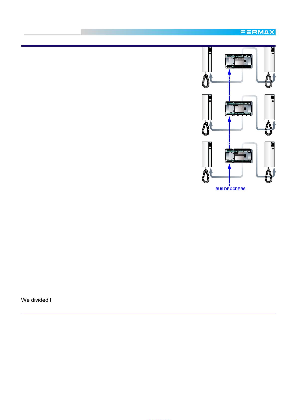
The main feature that makes MDS Systems special is that they need no
call wires, so the installations are BUS type, with only one cable rising
through the building, interconnecting the Decoders installed on the floors,
in which the terminals corresponding to each floor are connected.
The call is generated in the decoder itself and sent to the telephone called.
In order to differentiate if the call comes from an outdoor panel or from a
guard unit, the call tone is different in each case.
Thanks to the BUS features, decoder and distributor installation split any
point of the installation into as many branches as required.
Both telephones and monitors can be basic models, but thanks to the
system features they work in privacy mode, that is, they are disconnected while they are not called, avoiding other telephones hearing the
conversation in which they are not concerned or opening the door.
For the same reason, a telephone that has been left accidentally off the
hook would not affect the rest of the system.
It is also possible, from these standard terminals, to receive and generate calls from/to the guard units.
This system is designed for medium to large installations in which the
traditional systems, with one call wire per telephone, would complicate
the installation.
-V
AUDIO DECODER 4
REF. 2 4 24
DECODER Nº:
6578
TELEFONOS /
TELEPHONES
PGM
2134
D2D1
-V
AUDIO DECODER 4
REF. 2 4 24
DECODER Nº:
6578
TELEFONOS /
TELEPHONES
PGM
2134
D2D1
-V
AUDIO DECODER 4
REF. 2 4 24
DECODER Nº:
6578
TELEFONOS /
TELEPHONES
PGM
2134
D2D1
%86'(&2'(56
For the same reason, this system is aimed at condominiums with one or
more general entrances (with or without guard unit) and several internal
blocks that can have, at the same time, one or more accesses with or
without guard units.
There is no practical limit to the number of blocks, entrances, guard units or dwellings that a MDS
system can manage.
The main features of the MDS systems are:
* Complete privacy of speech and door control, assuring privacy for your conversations.
* Standard terminals installed in the apartments.
* Bus type installation enables all possibilities of connection and extension.
* Floor distribution, making wiring fault and failure detection easy.
* Isolation, between terminals by means of the decoders.
We divided the MDS system into three types:
MDS DIGITAL
For installations in which any of these facilities are required:
Searching resident's name through the outdoor panel display (electronic directory).
Any type of access control and/or access restriction: proximity card readers, button key, numeric
keypad, etc. The system admits up to 32 accesses per Central, and manages access restriction
depending on different parameters: access number, day of the week and 3 timetable bands for each
user. See the MDS PC Programming Manual for further details.
Additonal security (alarm system management, panic pushbutton to alert the guard or watching per-
sonnel, etc.). See the MDS PC Programming Manual for further details.
Automation (lift control, lights on/off, watering sprinklers, etc.). See the MDS PC Programming Ma-
nual for further details.
Pag. 3
Page 4
Technical Book
MDS
MDS
The management capability of one MDS Central Unit is:
Up to 32 panels. These panels can be:
- Access control panels
- Audio/video panels
- Guard Units
Guard units and Audio/video panels require a Switcher Module ref. 422
each one. The maximum number of Switcher Modules that one Central
Unit can allocate are:
Central Unit ref. 2420: 2 units.
Central Unit ref. 2421: 10 units.
This limits the maximum audio/video panels and guard units to allocate in
the same Central Unit.
Up to 10.000 telephones or monitors
Up to 1.000 sensor inputs
Up to 1.000 relay outputs
Up to 1.000 1L City audio panels (for single houses).
This capability can be increased with no practical limits, because it is possible
to interconnect up to 64 Central Units by means of the FXL (FERMAX LINK)
interface.
LCD DIGITAL SYSTEM
123
456
789
A0B
GUARD UNIT
62
6312 4213464132632164
D1D2
+-
-V
BUS
MADE IN SPAIN
REF. 2424
DECODER Nº:
TELEFONOS /
TELEPHONES
PGM
BUS
+-
D2
D1
26
6312 4213464132632164
D1D2
62+-
BUS
MADE IN SPAIN
REF. 2424
DECODER Nº:
TELEFONOS /
TELEPHONES
PGM
BUS
D2
D1
+-
26-V6312 4 21346 4132632164
PANEL 0
CT
V
M
+
SA
SB
2
6
PANEL 1
CT
V
M
+
SA
SB
2
6
DECODER
DECODER DE AUDIO 4
AUDIO DECODER 4
6578
2134
6312 4 21346 41326 32164
DECODER
DECODER DE AUDIO 4
AUDIO DECODER 4
6578
2134
CENTRAL
+CTVM D26D21-+
-
INPUT
DECODERS
UNIT
NR-2055
HIGH RESOLUTION
CCD CAMERA
PAN &TILT
LCD DIGITAL SYSTEM
123
456
789
A0B
OUTDOOR
PANEL
Each Central Unit can control up to 31 panels instead of 32, because one of them is used for the FXL (see
note).
The maximum number of Switcher Modules (and consequently the maximum mumber of audio/video
panels and/or guard units) are:
Every Central Unit ref. 2420: 1 units.
Every Central Unit ref. 2421: 9 units.
The number of telephones/monitors, sensors and relays for each central unit are listed above.
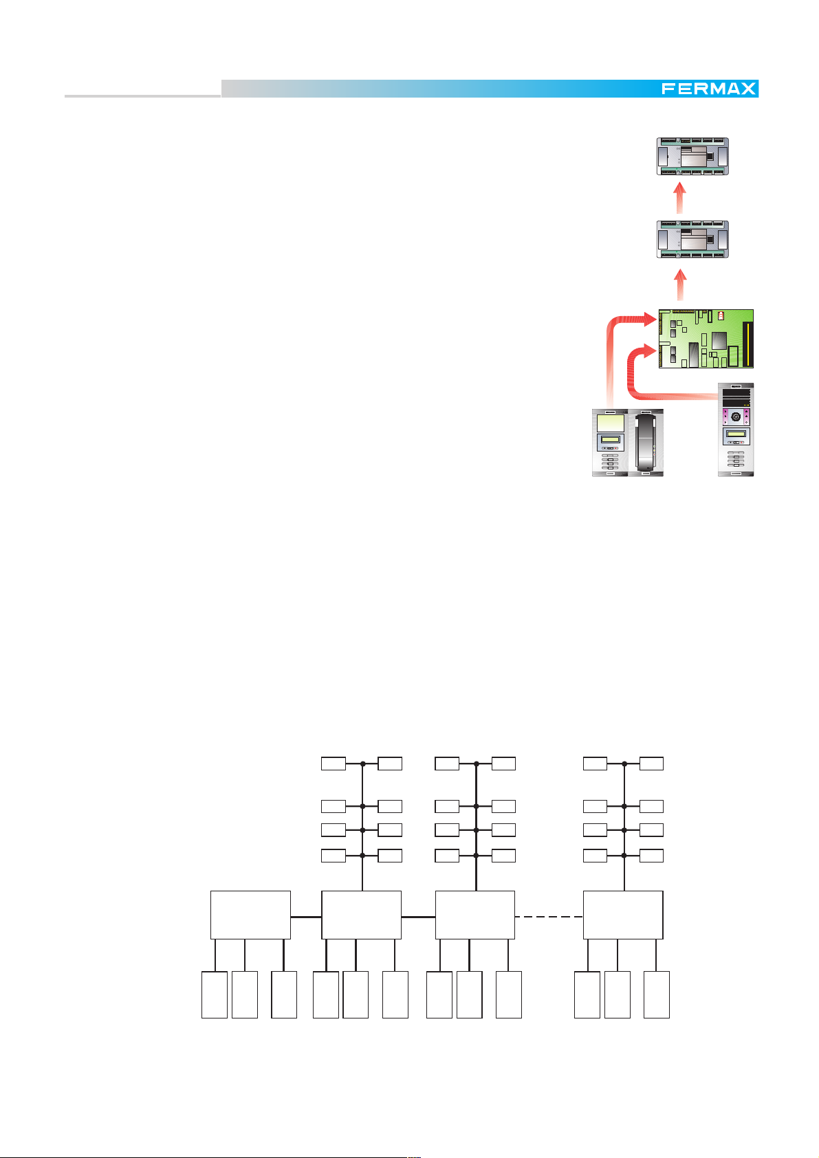
In these type of installations, usually in big condominiums with one or more general entrances and several
internal blocks, one Central Unit is used to control the general entrances. Each block is also controlled by
means of one Central Unit. All the Central Units are interconnected by means of the FXL.
As this is a multiplexed system, both FXL and BUS DECODER can be configured as bus, star or a
combination of both.
CENTRAL Nº 00
GENERAL ENTRANCES
FXL
BUS DECODER
CENTRAL Nº 01
INTERNAL BLOCK
BUS DECODER
CENTRAL Nº 02
INTERNAL BLOCK
BUS DECODER
FXLFXL
CENTRAL Nº 63
INTERNAL BLOCK
PANEL
Nº 0
PANEL
Nº 1
PANEL
....
Nº 9
PANEL
Nº 0
Nº 1
PANEL
....
Nº 9
PANEL
Nº 0
PANEL
Nº 1
PANEL
....
Nº 9
PANEL
Nº 0
PANEL
Nº 1
PANEL
....
Nº 9
PANEL
Note:
* Central Unit nº 0 is usually reserved for general entrances. No decoders are usually connected to it unless
there are single housing units (villas) and/or access control in the main installations, in which case, the
required decoders are connected.
Pag. 4
Page 5
Technical Book
MDS
MDS
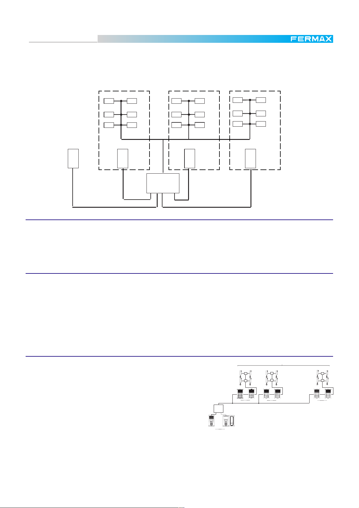
In the case of small condominiums (maximum 100 apartments per block) it is possible to use one Central
Unit only, with one, two or three Outdoor Panel for each block, sharing the decoders between the blocks.
Guard Unit and /or general entrances are also possible, but taking into acccount that the maximum number
of panels is 10. This is the called Multistair System, only available with MDS V 3.1 or higher.
DECODER BUS
BLOCK 9
PANEL
Nº 1
GENERAL
ENTRANCE
PANEL
Nº 0
DECODER BUS
BLOCK 1
PANEL
Nº 1
CENTRAL Nº 00
....
BLOCK 2
PANEL
Nº 1
DECODER BUS
MDS CITY
Buildings up to 100 dwellings and up to a maximun of 15 entrances in which, for aesthetic or functional
reasons, pushbuttons panels are preferred.
Calls are made by pressing the corresponding pushbutton.
Neither access control nor automation are possible, since relay and sensor decoders are not admitted.
MDS DIRECT
Buildings up to 100 dwellings and up to a maximum of 15 entrances, in which for aesthetic or functional
reasons a numeric keypad is preferred for calling dwellings . You can call a dwelling by tapping the
dwellings number on the keypad.
A directory installed beside the numeric keypad is needed to state the name and number of each
dwelling. The keypad also allows access control for 100 users.
Condominiums with a main entrance and up to 100 internal blocks
Neither access control nor automation are possible, since relay and sensor decoders are not admitted.
MDS DIGITAL COMBINED WITH MDS CITY
Condominiums up to 99 internal blocks. Each block with
BLOCK 1 BLOCK 2 BLOCK 99
MDS CITY
a maximum of 99 dwellings, 31 general entrances and 1
guard unit.
...............
Several linked central units allow us to reach 6,237
blocks, maximum 99 dwellings each.
One conversation per block is possible simultaneously.
Meanwhile, another communication is possible between
the general entrance and any free block.
U.C. MDS
DIGITAL
2
1
3
5
4
6
8
7
9
0
A
B
31
1
9
1
9
123
456
789
A0B
1
MDS CITY panels are connected to the BUS DECODER. Decoders of each block are connected to
the corresponding MDS CITY panel.
Panels connected to the Central Unit are used for general entrances only.
It is also possible to connect audio decoders to the central unit (i.e. for single houses in the
condominium) and sensor/relays decoders, for security or automation purposes.
1
9
Pag. 5
Page 6
Technical Book
MDS
MDS
MDS DIGITAL COMBINED WITH MDS DIRECT
Condominiums up to 15 internal blocks. Each
BLOCK
1
block with a maximum of 99 dwellings, 31 general entrances and 1 guard unit.
Several linked central units allow us to reach 6,237
2
1
3
2
1
3
5
4
6
5
4
blocks, maximum 99 dwellings each.
One conversation per block is possible
simultaneously.Meanwhile,another
communciation is possible between the general
entrance and any free block.
U.C. MDS
DIGITAL
2
1
3
12 3
5
4
6
45 6
8
7
9
78 9
A0B
0
A
B
31
1
6
8
7
9
8
7
9
0
A
B
0
A
B
1
9
MDS DIRECT panels are connected to the BUS DECODER. Decoders of each block are connected
to the corresponding MDS DIRECT panel.
Panels connected to the Central Unit are used for general entrances only.
It is also possible to connect audio decoders to the central unit (i.e. for single houses in the
condominium) and sensor/relays decoder, for security or automation purposes.
MDS DIRECT COMBINED WITH MDS CITY
BLOCK
2
1
5
4
8
7
0
A
1
3
6
9
B
MDS DIRECT
2
2
1
3
5
4
6
8
7
9
0
A
B
9
...............
BLOCK
2
1
3
5
4
6
8
7
9
0
A
B
1
99
2
1
3
5
4
6
8
7
9
0
A
B
9
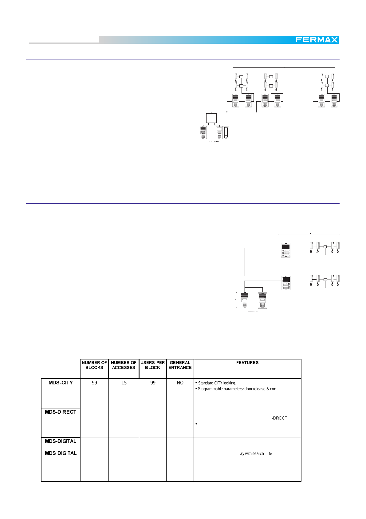
This system has been devised for office buildings in which there are several offices on each floor. It is also
suitable for small condominiums, using MDS DIRECT for general entrances, and MDS CITY for blocks.
MDS CITY
Office buildings. In the main access to the building
OFICCE 99
we install a MDS DIRECT panel for calling any offfice
in the building, and in each of the floors we install a
MDS CITY for calling the offices in this floor.
One conversation per block is possible simul-
...............
OFFICE 1
taneously. Meanwhile, another communciation is
possible between the general entrance and any free
block.
Neither access control nor automation are possible,
since relay and sensor decoders are not admitted.
0'6&,7<
180%(52)
%/2&.6
99 15 99 NO • Standard CIT Y looking.
180%(52)
$&&(66(6
86(563(5
%/2&.
*(1(5$/
(175$1&(
• Programm able param eters: door r elease & con v er sation time.
• One MDS-DIRECT Guard U nit.
MDS DIRECT
2
1
3
5
4
6
8
7
9
0
A
B
15
)($785(6
2
1
3
5
4
6
8
7
9
0
A
B
1
Pag. 6
0'6',5(&7
0'6',*,7$/
0'6',*,7$/
99 10 99 Y ES • Access keypad (100 codes).
• Display for programming MDS-CITY & MDS- DIRECT.
• One MDS-DIRECT Guard U nit.
64 32 10,000 Y ES • PC Management.
• Several Guard Units allowed.
• Electronic Directory: display with search feature.
• In dividual Access Code.
• Special decoders managem ent.
• Digital Control ler f eatures.
• Integral testing.
Page 7
Technical Book
MDS
MDS
DECODERS
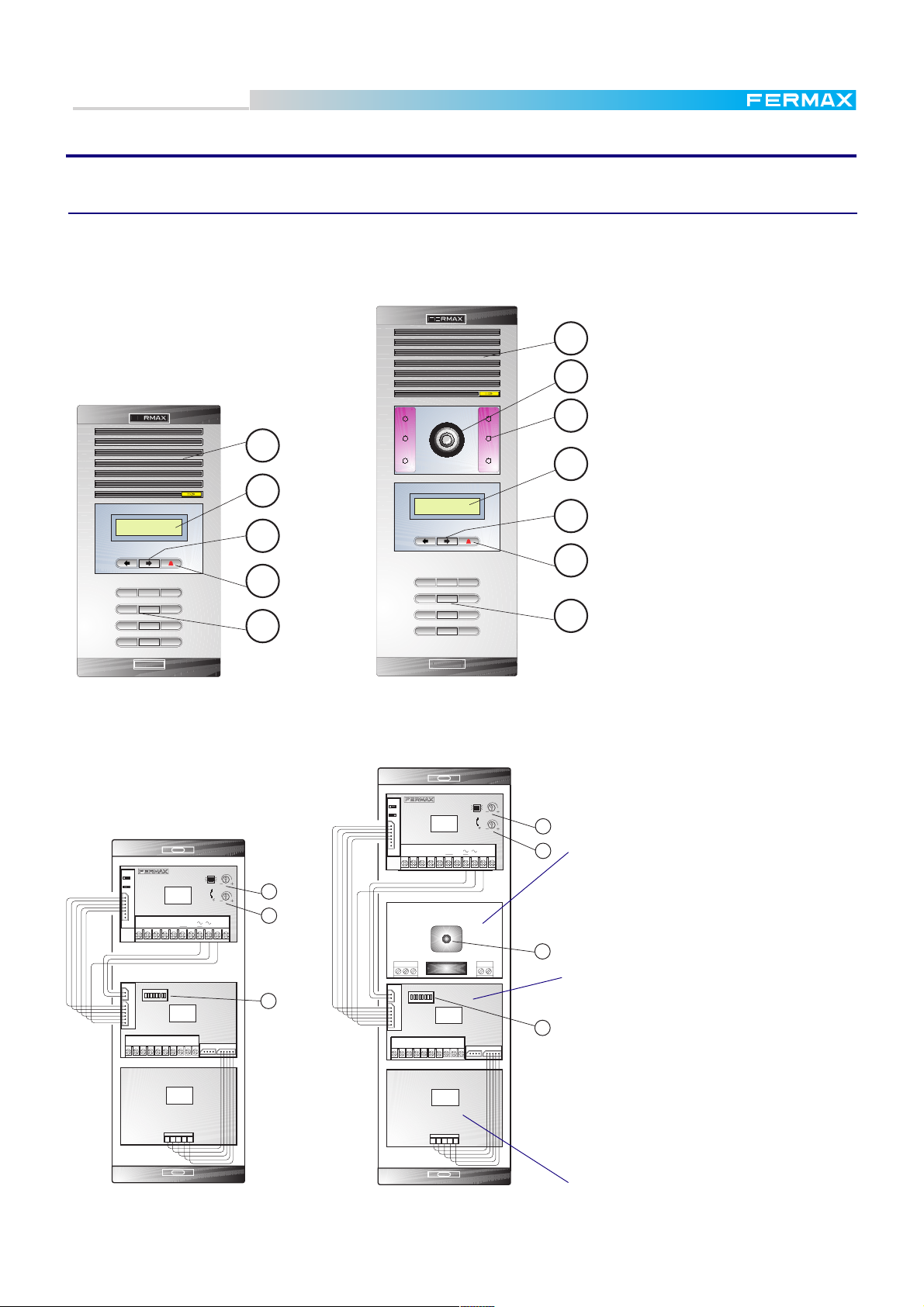
These are the interface between the MDS BUS and the external devices (telephones, alarm sensors, etc.)
There are 7 different types of decoder to be used in the MDS systems.
Audio decoder 4. Used in standard installations. Provides connection for up to 4 telephones.
Audio decoder 8. The same as above, but providing connection for 8 telephones.
Audio Isodecoder 4. In addition to the audio decoder 4, provides total isolation of each telephone
from the rest of the installation (including the other telephones in the systems) and other panic calls.
Sensor decoder. Provides up to 8 alarm sensor inputs.
Relay decoder. Provides up to 8 relay contact outputs.
Panel decoder. Provides connection up to 4 standard 1 line City Panel.
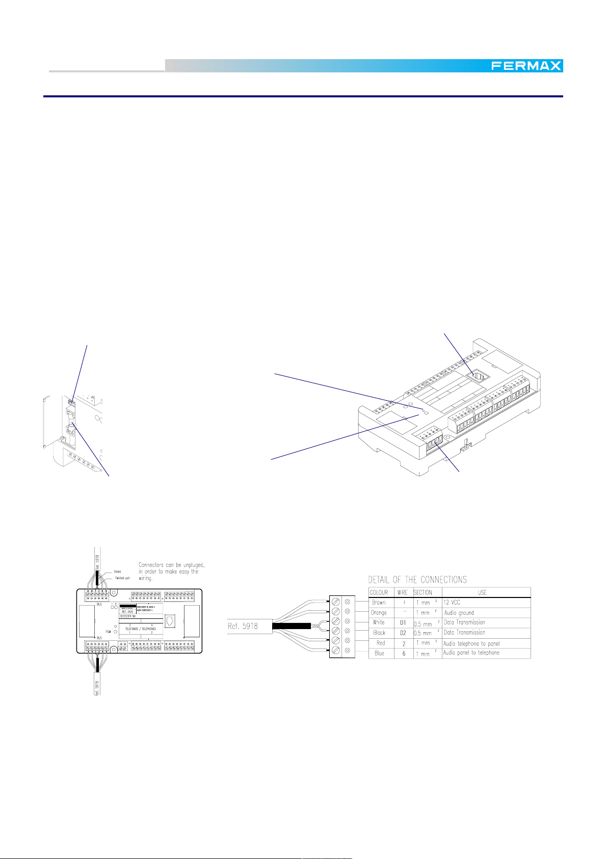
All of them have the same appearance, with some parts that are common to all of them. These parts are
represented in the diagram below. Some specific parts of each one are represented in other diagrams.
Telephone jack socket
(only audio decoders)
PC Programming connector (under the cover)
N
I
A
P
S
N
I
E
D
A
M
REF. 2425
DECODER Nº:
BUS
D2D1
DEC
8
DIO
E AU
D
DER 8
ER
D
CO
O
E
DIO D
AU
768
5
12 43
TELEFONOS / TELEPHONES
422
2
13
62
6
4
3
1
63
4
2
1
6
4
3
1
6
BUS
BUS
PGM
LED indicator
(see text on next page)
- V
BUS
FERMAX
- V
PGM
PGM button
0,5 A protection fuse.
MDS BUS connector
The MDS BUS is common for all types of decoders, independently of the decoder type. The connection
between the decoders and with the outdoor panel (or central unit) is by means of a bus consisting of 4
wires + 1 twisted pair (FERMAX cable REF.5918):
There is no limit to the number of decoders connected to an MDS system. The maximum number depends
on the devices connected. In any case, these specifications must be followed:
* Distance from the decoder to the telephone/monitor must always be less than 100 m.
* Maximum distance between the last decoder, and Outdoor Panel (or Central Unit), without repeaters
is 1.200 m.
* Maximum number of decoders without repeaters is 120.
Pag. 7
Page 8

Technical Book
MDS
MDS
Since the decoders are digital devices they must be programmed before being used.
They can be programmed once installed or even in your warehouse (before installation), because the
assigned codes (telephone numbers) are stored into each decoder (EEPROM memory) and are not deleted even in case of power failure. However, the settings can be updated as many times as required.
See the MDS Programming Manual for further details.
Programming process is different depending on the system where they are being installed: MDS-DIG-
ITAL, MDS-CITY or MDS-DIRECT. See the instruction manuals for details. In any case, the decoders can
be programmed from a PC using the Programmer Module Ref. 2427, which also includes the required
software (DECOWIN). This module is inserted into the Programming connector.
In any case, use a small screwdriver to press the PGM button, through the hole when the system requires
it, in order to codify the lines of this decoder. See diagram on the previous page.
It is also possible to program the decoders from the telephones, if audiodecoder is V1.1 or
higher, and always in MDS Digital installations, it not being necessary to press the PGM button at the decoder, just the lock button on the telephone. See the MDS Programming Manual
for further details.
The LED indicator in the decoders gives us important information about their status:
OFF: decoder still has not been programmed.
ON: decoder is in programming mode.
BLINKING: decoder has been codified and is working.
* blinks twice every 3 seconds: indicates that the Central Unit in which the
decoder is connected to is in day mode.
* blinks once every 3 seconds: indicates that the Central Unit in which the
decoder is connected to is in night mode.
The DAY and NIGHT modes are a property of the central unit.
The audiodecoders have a telephone jack socket which gives the installer the possibility to plug-in a
standard FERMAX handset to speak from the decoder to an outdoor panel or to any telephone connected
to this decoder.
This telephone jack, which is connected directly to audio lines of the BUS installation, is a great help to the
installers when they are programming the system. An installer can stay at the outdoor panel for programming, while another goes by the decoders pressing the PGM button (or the lock telephone button if possible).
Both can talk to each other through the handset connected to the telephone jack socket on the decoder
that they are programming at any time).
The technical data for each kind of decoder is:
Audiodecoder calling: 400 mA
Audiodecoder in stand-by: 40 mA
Sensor decoder: 40 mA
Relay decoder: 160 mA (maximum)
Operating voltage: 12 Vdc (minimum 10 Vcc)
Pag. 8
Page 9
Technical Book
MDS
MDS
Another important point to take into account (regarding the decoders) is that the voltage along the bus-line
may drop, due to the wire resistance. To avoid this, it is necessary to install additional 12 Vdc power
supplies to regenerate the 12 Vcc in long installations.
You can use for this the REF.8840 Power Supply or the REF.8837 (12 Vdc 0,75 A), which can be enough, in
somes cases, to keep the voltage level in range. See table and explanation below.
On the other hand, in installations where the decoder bus wires are very long we recommend using a
bigger wire section.
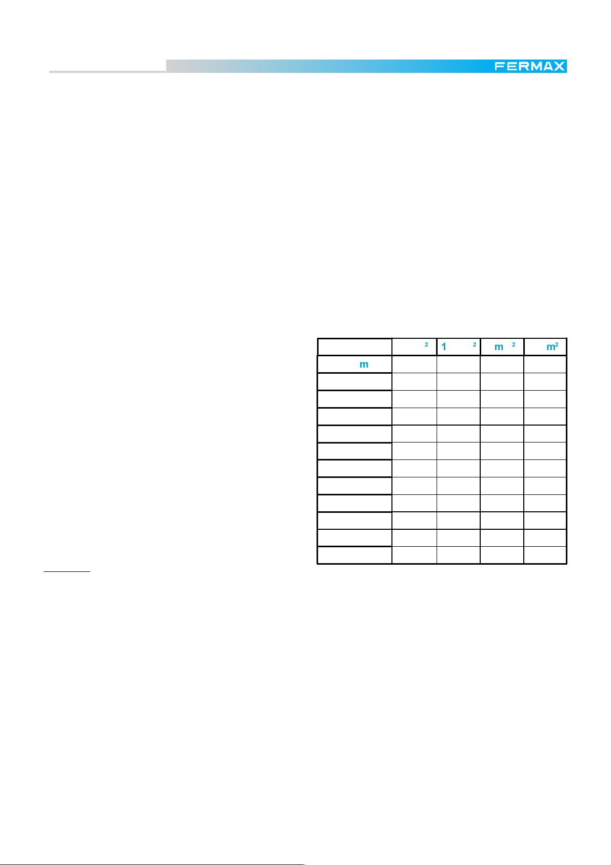
The next table shows how many decoders can be installed in terms of the distance and section of wire
utilised.
It shows the number of decoders that can be connected in relation to the power supply point (before having
to instal an additional one), the wire section used and the type of power supply, ref.8837 or ref.8840 (in blue,
between brackets).
* In the left-hand column is the distance that a power supply can cover.
* In the top row the section of the wires to be used.
* In the intersection is the maximum number of decoders that may be connected with these specifica-
tions. (In blue, in brackets, if using a Ref. 8840 supply, whereas the others refer to Ref. 8837.)
We can "play" with these parameters in order to find
the most suitable relation between the wire section
and the number of power supplies required.
'LVW6HFFLyQ PPPPPPPP
P
P
P
P
P
P
P
P
P
P
P
.P
10 10 (15) 10 (22) 10 (30)
7 9 10 (15) 10 (22)
57910 (17)
46810 (13)
4 5 7 10 (11)
3469
2357
2346
1234
1224
1123
1123
Example:
We have to stretch 20 decoders along 500 metres (1 decoder each 25 mts aproximatelly) in a very
long installation.
* We are using 10 decoders every 250m, so the best option is to use 3 mm
2
wires. Then we only need
one support power supply at 250m from the central unit. The first 250m are powered by the power
supply in the central unit.
* If using 1 mm
2
wires, we would need to add one power supply every 150m (we are using
approximately 7 decoders every 150m). We would need 3 additional Ref. 8837 power supplies.
Note:
* The wire section of the Ref. 5918 cable recommended by FERMAX for bus installation is 1 mm
2
.
* If we can plan the structure of the installation, it is best to use "star" topology as much as possible . This
would reduce the total distance between the central unit and the last decoder in each branch, and
consequently the number of additional power supplies.
* In any case, using thick wires in very long installations is the best, because this is the only way to avoid the
audio level decreasing.
Pag. 9
Page 10
Technical Book
MDS
MDS
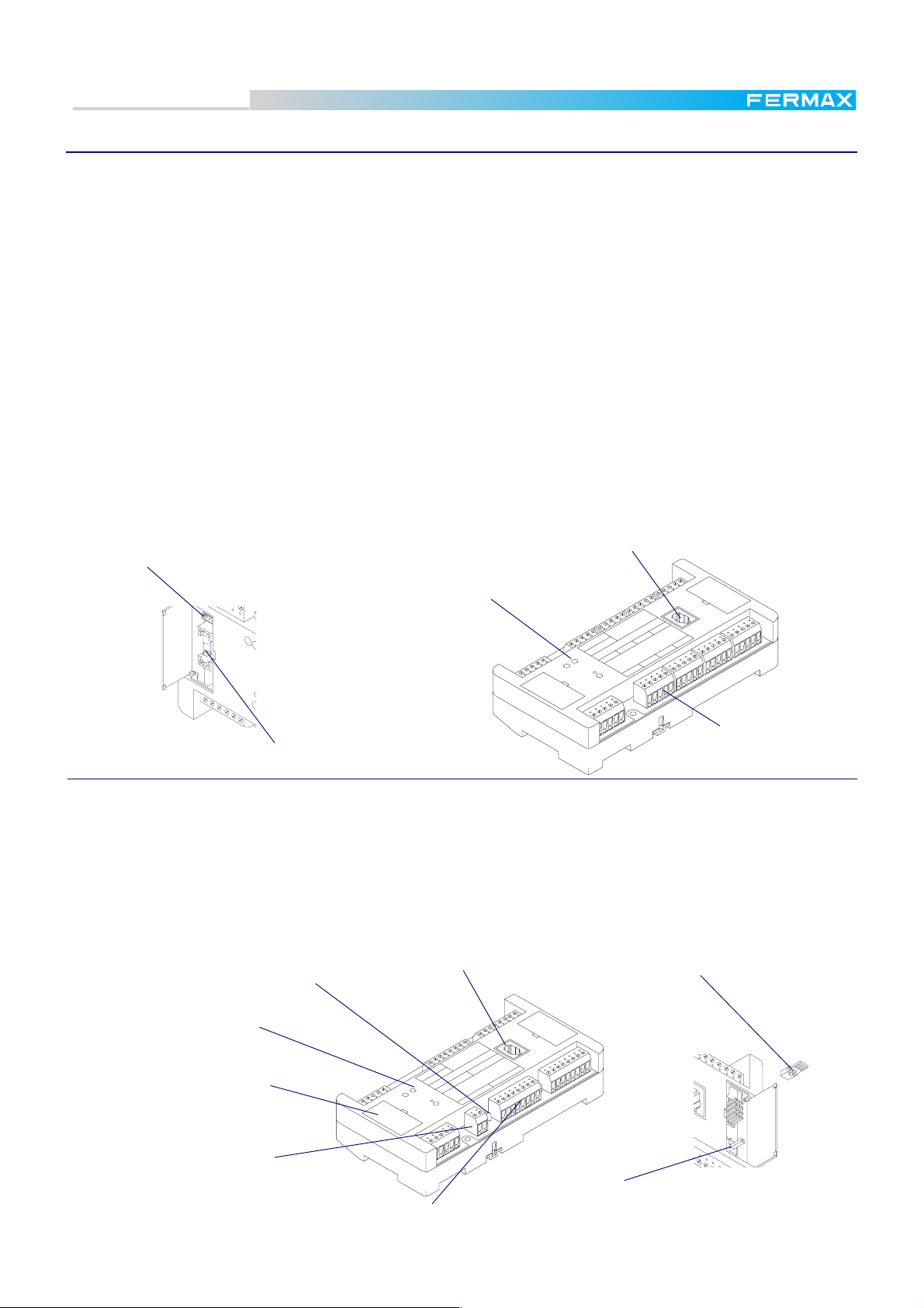
Audiodecoder 4 Ref.2424 & Audiodecoder 8 Ref.2425
These standard decoders are used for audio/video installations.
The telephones connected to a decoder are isolated from the rest of the installation (except the ones in the
same decoder). Any fault in a telephone will not affect any other in the installation, except the ones installed
in the same decoder (possibly affected).
Once programmed, the decoder receives the call code from the decoder BUS and generates a call signal
to the corresponding telephone if the code is acknowledged, connecting audio bus to this telephone. After
the conversation, decoders detect when telephone is hang up and cut communication.
Each decoder output (telephone connector) works as a standard City Panel 1AP101, with the corresponding connections:
nº 1: power supply to microphone (electret type)
nº 2: audio from telephone to panel
nº 3: negative
nº 4: call signal
nº 6: audio from panel to telephone
The maximum amount of terminals to be connected to each output is 3 telephones (for the same apartment). The more telephones installed, the lower the call sound.
PC Programming connector
Test handset jack
V connector (to synchronize
distributor in video installations)
BUS
BUS
PGM
- V
- V
BUS
N
I
A
P
S
N
I
E
D
A
M
FERMAX
REF. 2425
DECODER Nº:
PGM
BUS
DECODER DE AUDIO 8
AUDIO DECODER 8
5
12 43
TELEFONOS / TELEPHONES
62
D2D1
768
1
6
4
3
1
6
422
2
13
6
4
3
1
63
4
2
Telephone connector
0,5 A protection fuse
Isodecoder Ref.2426
4 units in ref 2424
8 units in ref 2425
In addition to the audiodecoder features, isodecoders have individual isolation for each output. This means
that a failure in any telephone would not affect the rest of the installation, including telephones connected to
the same decoder. Moreover, isodecoders have extra features, such PANIC CALL terminal and activation
signal. Therefore, apart from the standard terminals that every decoder has, some extra terminals are
included for each output:
nº X: for special functions (to turn on a busy line LED in the telephones, generally)
nº P: panic call input (only in MDS-DIGITAL using panic call features)
Test jumpers:
LED indicator
is ON when the telephone is selected
Test handset jack
T-Communicates telephone with the test handset
N-Normal operation.
V connector (to synchronize
distributor in video installations)
PC programming connector
and 0,5 A protection fuse
under the cover
X terminal (duplicated)
Pag. 10
- V
BUS
Telephone connector
4 units
MADE IN SPAIN
FERMAX
REF. 2426
PGM
BUS
ISODECODER AUDIO 4
AUDIO ISODECODER 4
3
DECODER Nº:
TELEFO
6
2
D2
D1
X
4
NES
2
S / TELEPHO
NO
1
X
P
6
4
3
2X
1+
P
6
34
2
1
+
X
Testing switch:
N-Handset connect with outdoor panel
T-Handset connect with internal telepone
selected with test jumpers.
T
Page 11
Technical Book
2
:
D
R
NC
MDS
MDS
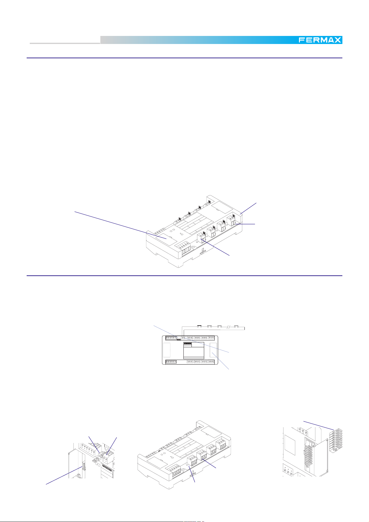
Sensor decoder Ref.2429
This decoder has been designed to work with MDS-Digital systems only
It has 8 sensor inputs that can be configured either to use N.O. (normally open) or N.C. (normally closed)
detectors by means of a jumper located beside each input. In both cases the activation signal can be sent
to the central unit immediately or delayed, depending on the "time" parameter that commands the alarm
signal.
Instant alarm: signal activation is sent to the central unit the moment that sensor activation is detected.
Bear in mind that the detection stays on as long as the sensor keeps detecting. The time parameter for this
function is "0".
Delayed alarm: signal activation is sent to central unit when the sensor has been activated for a programmed period of time (from 1 to 127 seconds or minutes)
"Time"and "sensor number" parameters are programmed into the decoder, and stay programmed even if
it is disconnected from the electric power. The "sensor number" can be programmed either from any
keypad with display or through a PC (by means of the Ref. 2466 module and the DecoWin software).
"Time" parameter is always programmed through a PC. See the "PC Programming Manual" for more
details.
PC Programming connector
under the cover
Relay decoder Ref. 2430
DECODER DE SENSORES
SENSORS DECODER
AX
M
IN
A
P
S
IN
E
D
A
M
FER
EF. 2429
R
DECODER Nº:
BUS
5
PGM
BUS
6
2
D2
D1
SEN
6
SO
1
78
ES / SEN
R
2
4
S
R
SO
3
S- S
-
S
-S
-
Sensor connector
8 units
NC/NO sensors selector
LED indicator
is ON when the connected sensor
is activated
Provides relay outputs for alarm and automation purposes. Exclusively to work with MDS-Digital systems.
It has 8 relay ouputs, which can be configured either as flip-flop (relay toggles in each activation) or as
timed mode (closing time for each relay can be set from 1 to 255 seconds). For "timed mode" a timer starts
to count the moment the relay is activated, releasing it once the time has expired.
Another interesting feature is the
FIRE ALARM facility.
This feature is achieved by means
of a connector (CN12), to connect
in series all the sensors we want
to use for detecting fire(forming a
loop connection), that would open
Jumper P1
C1
RELAY
DECODER
C3
Cn
CN-12 terminal.
TEST jumper
(under the cover)
If P1 is in ON then the loop in CN-12
has to be closed (Fire protection).
If P1 is in OFF, then the loop in CN-12
is not controlled.
For TEST jumpers be enable, P1 has to be
in ON.
C2
the loop when a fire alarm is generated somewhere. This signal would cause all the relays to be released in case of danger, for instance
allowing all the inhabitats to exit (releasing door locks controlled by the relays).
Max. current through the relay contacts: 2A (120-220V)
TEST jumpers. For checking
relay output. To be operative,
P1 has to be set in ON.
C
N
C
O
NC
C
NO N
C
N
C
O
Relay output (8 units)
PC Programming connector
P1
BUS
CN-12
2
D
1
D
+
O
N
F
+
V
M
A
D
E
IN
REF. 2430
S
P
A
IN
DECODER Nº
IN
A
P
S
IN
E
D
A
M
FERMAX
REF. 2430
DECODER Nº:
- V
BUS
PGM
BUS
D2
1
D
DECODER DE RELES
RELAYS DECODER
6
5
RELES / RELAYS
1
26
8
4
7
3
2
N
NC
C
NO
LED indicator
is ON when the connected relay is activated
Pag. 11
Page 12
Technical Book
MDS
MDS
Special Decoders: Panel decoder Ref. 2436
Special decoder for hands-free communication system. It enables us to connect standard City panels to
the decoder instead of telephones. Moreover, by means of these decoders we can achieve a system with
standard panels in the tenant rooms (e.g. in hospital wards) allowing the patient to call a concierge or
porter. Then, they can attend the patient as required (priorities) allowing hands-free talking for the user. If
there is any electrical lock attached to the panel, the porter will be able to release it. In installations with
panel decoders and audiodecoders, the porter can communicate any City panel with any telephone. The
maximum number of City panels in an MDS-Digital installation is 1,000.
Panel decoders can be programmed from a PC, from any MDS-Digital keypad with display or from an
MDS-DIRECT Guard Unit.
TEST jumpers (activates
the corresponding panel)
PC programming connector
PLACA / PANEL
4
2
P
6
A
3
226
C
P
6
A
3
2
C
Panel output
T
4 units
(under the cover)
BUS
DECODER DE PLACA
PANEL DECODER
N
I
A
P
S
N
I
E
D
A
M
FERMAX
REF. 2436
DECODER Nº:
- V
PGM
BUS
D1 D2
3
1
LED indicator
is ON when the panel is selected
The wiring between DECODER and Panel is shown in figure below. As shown in figure, the City panels can
also be used to call to a standard telephone.
Terminals description:
C: Call to "standard" porter
2 & 6: Audio from Guard Unit to City panel and viceversa respectively
3: Negative
A: Door release control
P: Call to PANIC Guard Unit
T Call to telephone
C Call to porter
P Call to PANIC guard
3
EXT.
AMP. KIT SMD
INT.
101CI14A
Ab1Ab
2
36
Cp
L-
15 ohm.
1/2 W.
15 ohm.
1/2 W.
L
Cp
L
-
2
AMP. KIT SMD
101CI14A
Ab1Ab
6
3
2
A
C
P
CP
EXT.
INT.
2
36
L-
6
3
2
A
C
CT
REF.8787 REF.8787
NR-2086
220 Vac220 Vac
12 43
56
SEC. 12VACPRIM. 220VACPRIM. 220VAC SEC. 12VAC
15 ohm.
1/2 W.
15 ohm.
AMP. KIT SMD
Cp
L
AMP. KIT SMD
Cp
L
-
101CI14A
T C
101CI14A
P C
++
4
EXT.
AbAb
6
1
23
1
EXT.
Ab1Ab
6
32
NR-2086
INT.
L-
INT.
L-
1342 65
6
3
2
A
C
Ref. 5920
Ref. 5922
D2+-D1 62
BUS
6
3
2
A
C
P
BUS
6
DECODER DE PLACA
MADE IN SPAIN
PANEL DECODER
REF. 2436
3
PLACA / PANEL
PGM
DECODER N§:
A
26D1-+D2
C2 A36P C3A2
4
21
P632AC6PPC23
Ref. 5922
Ref. 5920
It is necessary to add a set formed of a 15 Ohm 1/2W resistor in series with a 1N4002 diode if call
confirmation tone in panel is required. Four sets of these are included with the Panel Decoder.
Pag. 12
Page 13

Technical Book
M
MV
-+
M
+
V
-
V
M
-+
V
+-
V
+-
M
D
IS
T
R
IB
U
ID
O
R
D
E
V
ID
E
O
8
V
ID
E
O
D
IS
T
R
IB
U
T
O
R
8
DISTRIBUIDOR/DISTRIBUTOR Nº:
BUS
PGM
BUS
- V
M
A
D
E
IN
S
P
A
I
N
REF. 2419
5
3
MONITOR
1
6
2
78
4
M
S
V
M
MDS
MDS
Decoder PC Interface Module Ref.2466
This module is used for programming the decoders, either before installation, using the PC Programming
Connector included in each of them, or after installation (using any PC Programming Connector in any
decoder connected to the MDS BUS or even from the PC Programming Connector in the Central Unit).
It can also be used for testing procedures, after installation. See included DECOWIN instructions for
further details.
Do not forget to set the SW1-2 configuration microswitch in
the Central Unit ( PROGRAMMING DECODER mode) to ON
position, during the programming process, and return it to
OFF positon afterward. See page 14.
Rx
Tx
On
Video Distributor 4 Ref. 2418 & Video Distributor 8 Ref. 2419
These devices are used in video installations only. Video distributors are normally placed beside the standard decoder and they are responsible for distributing the video signal for each monitor. Video distributors
are activated by the decoder they are attached to, whenever a call is generated in that decoder. The decoder thus sends a trigger signal through terminal "V", which is used to activate the distributor. As with the
standard decoders, the video distributors are manufactured in two versions or models: REF.2418 for 4
monitor (normally attached to Audiodecoder 4 Ref.2424) & Ref.2419 for 8 monitors (when Audiodecoder 8
is used REF.2425).
The Video distributors do not need to be programmed.
V
75 ohms load resistor
Cut junmper in all the decoder except in the last
one in the riser. See scematic diagrams.
VIDEO
DISTRIBUTOR 4/L
ISODECODER 4
BUS
BU
+-
PG
-
Monitor connector
Video BUS
connector
8 units.
+
-
VM
BUS
REF. 2418
V
-
VIDEO
1
BUS
V-+M
4
+
VM-VM
-+
+M-23-VM+
V
6D22
-+
D1
BUS
-
PGM
BUS
D2
D1
+ -
2 6
REF. 2426
V
3
TELEPHONES
1
XX
312 4 6P
P+X4 63+1 2PX6
4
2
X+1234
6P X
4321
+
Do not forget the "V" wire between audio decoder
and video distributor.
See figure alongside.
Pag. 13
Page 14
Technical Book
3
3
MDS
MDS
MDS Digital Central Unit
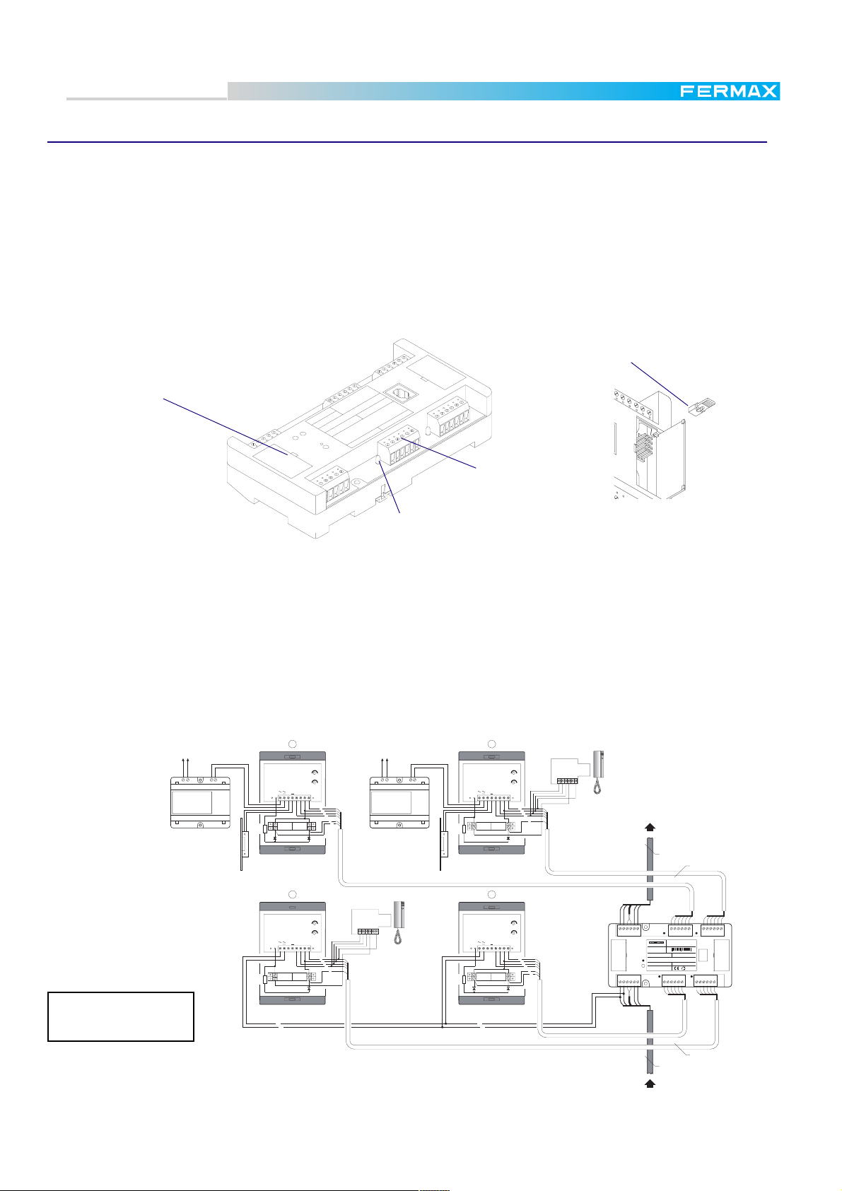
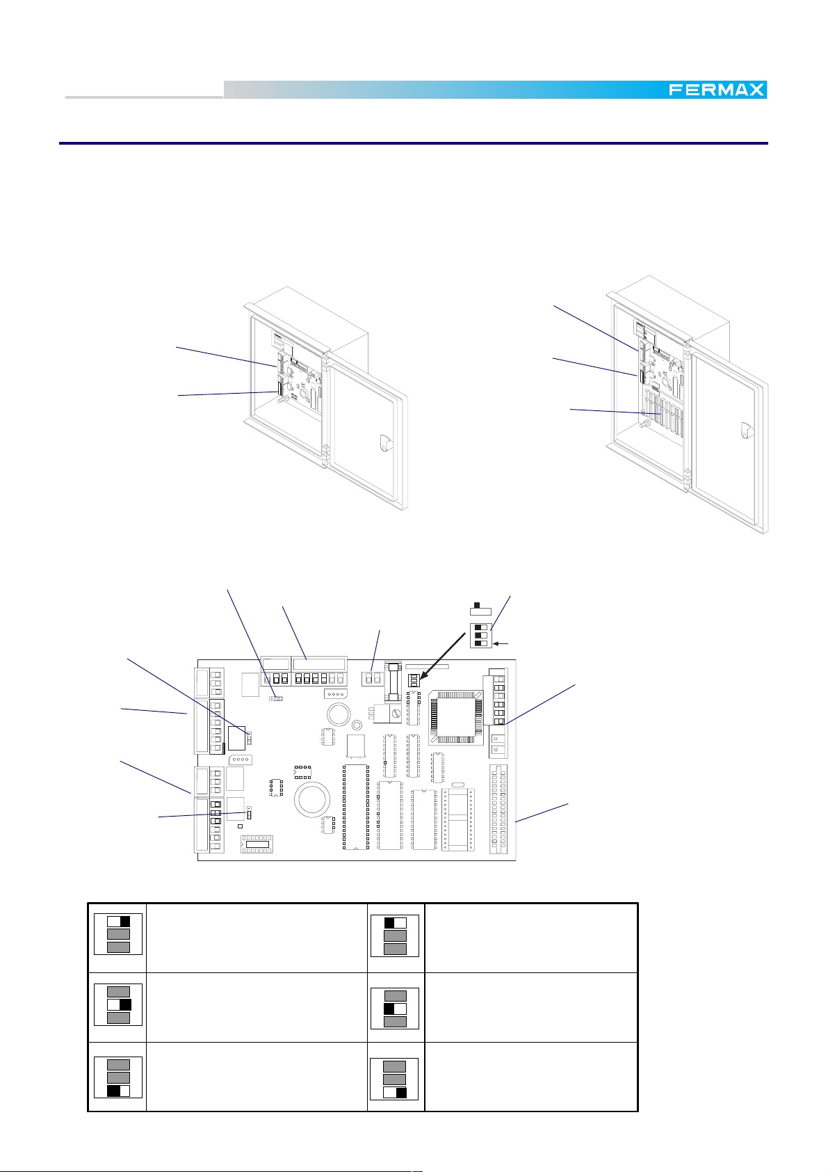
The Central Unit is the main core of the MDS DIGITAL system. The Outdoor Panels are connected to the
terminals provided for that purpose (see figure below for details).
Choose the model of Central Unit depending on the quantity of Audio/Video panels to install (unit for 2
panels REF.2420 and unit for 10 panels REF.2421).
I
PANEL 0 connector
M
A
D
E
IN
R
S
P
E
A
I
F
N
.8
8
4
0
5
0
-60
H
z.
80
VA
MA
X.
A
T
!
E
N
C
I
O
N
PANEL 0 connector
PANEL 1 connector
M
A
D
E
IN
R
S
P
E
A
IN
F
.
8
P
R
8
IM
.
4
8
5
1
0
3
5
V
1
7
E
5
F
-
2
7
0
V
E
5
F
0
-
6
0
H
z
.
8
0
V
A
M
A
+
X
A
-
.
1
T
2
!
E
V
N
+
C
4
1
I
A
O
3
.
8
N
V
C
2
A
A
U
T
I
O
N
B
A
A
T
T
T
E
N
T
I
O
N
R
E
D
CT
V
M
M
V
CT
+
6
2
-
D2
D1
S
P
0
A
+
S
B
2
R
D
X
TD
O
6
N
X
D
CO
E
1
PA
N
J0
EL
CT
V
M
R
PX
TP
X
+
P
O
W
ER
SA
O
N
SB
P
J1
1
2
6
S
W
IT
C
H
E
R
S
PANEL 1 connector
PANEL 2 to 9 connectors
C
A
U
T
IO
N
B
A
A
T
T
T
E
N
T
I
O
N
R
E
D
CT
V
M
M
V
CT
+
6
2
-
D2
D1
SA
P
0
+
SB
2
R
D
X
T
ON
D
6
X
P
A
N
J
E
0
L
CT
V
M
R
P
X
T
P
X
+
P
O
W
E
R
SA
ON
SB
P
J1
1
2
6
S
W
IT
C
H
E
R
S
REF.2420
Central Unit 2 Panels
REF.2421
Central Unit 10 Panels
The meaning of LEDs and use of jumpers and microswitches are explained below.
J2 (see table on the next page)
J0 (see table on the next page)
PANEL 0
CT
V
M
PANEL 0
connector
PANEL 1
connector
J1 (see table on
next page)
+
SA
SB
2
6
PANEL 1
CT
V
M
+
SA
SB
2
6
PIN_PADSTACKPIN_PADSTACKPIN_PADSTACKPIN_PADSTACKPIN_PADSTACKPIN_PADSTACK
P1
SWITCHERS
DECODER BUS
CT
D1
D2
V
M
2
6
-
Supply input
+
+-
INPUT
DECODERS
SW1
ON
1
32
MDS - BASE MODULE
SW1
Configuration microswitches (see table below)
ON
ON
321
SW1SW1-
A
B
G
A
B
G
EXTENSION INTERFACE
INTERFACE SOCKET
Extension socket
Pag. 14
SW1
ON
1
2
3
1
2
3
Keypad access code ns ont allowed
(except from guard units)
SW1
ON
PC TEST mode.
PROGRAMMING DECODER mode
Data transmission between Panels
SW1
ON
1
2
3
SW1
1
2
3
Keypad access code is allowed
ON
Normal mode
and Decoders is disabled
SW1
ON
1
2
3
Digital Controller system Audio or Video standard system
SW1
ON
1
2
3
Page 15
Technical Book
MDS
MDS
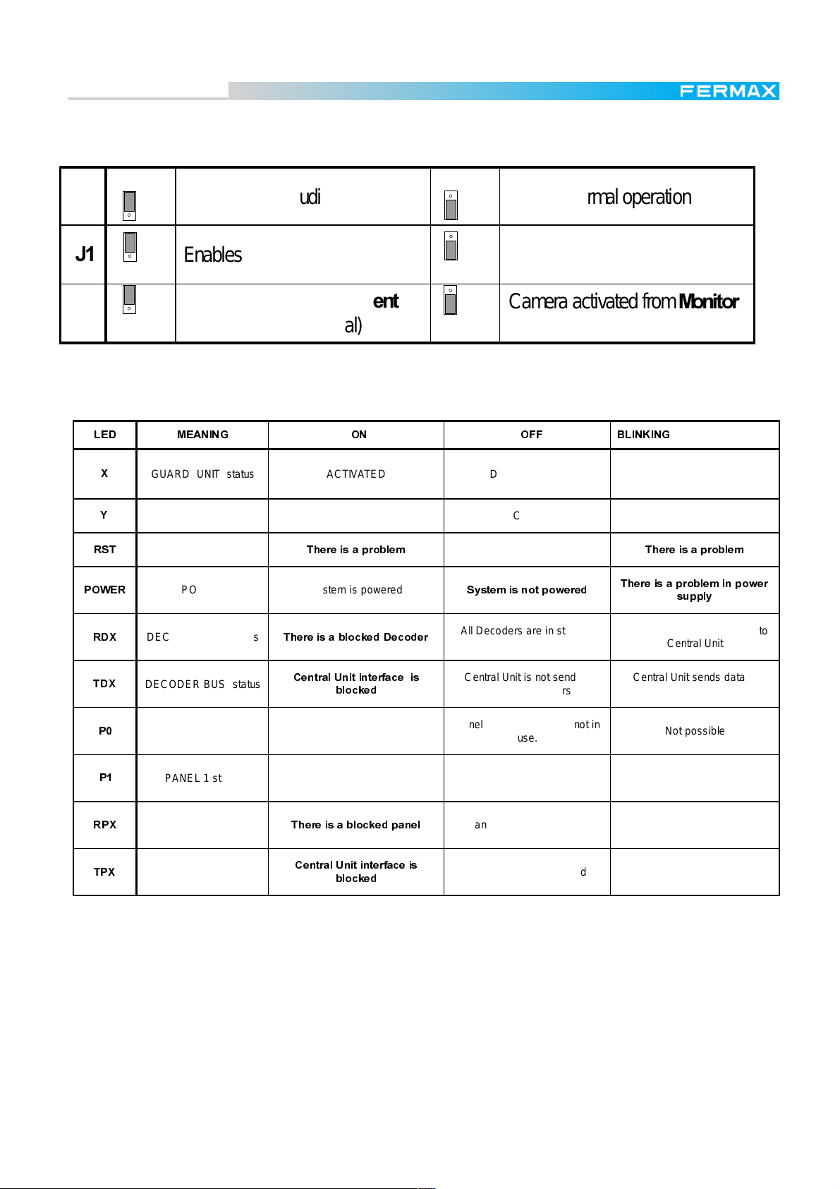
The tables below indicates the use of the jumpers in the MDS Central Unit (see note below ).
-
-
ON
En ables direct audio w ith3DQHO N orm al operation
ON
En ables direct audio w ith3D QHO N orm al operation
I
C ame ra a c tiva ted fro m &HQWUDO
OFF
OFF
E
Camera activa ted from 0 RQLWRUV
-
8QLW (CT signal)
The LEDs in Central Unit provide important information about the central unit status.
/(' 0($1,1* 21 2)) %/,1.,1*
;
<
567
32:(5
GUARD UNIT status ACTIVATED DEACTIVATED System is in PC MODE TEST
PANIC MODE status ACTIVATED D E AC TIVATED not possible
RESET system
MAIN POWER status System is powered
7KHUHLVDSUREOHP
All is correct
6\VWHPLVQRWSRZHUHG
(C T signal)
7KHUHLVDSUREOHP
7KHUHLVDSUREOHPLQSRZHU
VXSSO\
5';
7';
3
3
53;
73;
DECODER BUS status
DECODER BUS status
PANEL 0 status
PANEL 1 status
PANEL BUS status
PANEL BUS status
7KHUHLVDEORFNHG'HFRGHU
&HQWUDO8QLWLQWHUIDFHLV
EORFNHG
Audio in panel 0 or Guard Unit is
in use
Audio in panel 1
in use
7KHUHLVDEORFNHGSDQHO
&HQWUDO8QLWLQWHUIDFHLV
EORFNHG
All Decoders are in standby
mode
Central Unit is not sending
data to D eco d e r s
Panel 0 or Guard Unit is not in
use.
P anel 1 is not
in use
All panels are in standby mode
Cent ral unit is not sending data
Some De co de r se nds data to
Central Unit
Cent ra l Unit se nds data to
Decoder BUS
Not possible
Not possible
Som e panel se nds data to
Central Unit
Cent ra l Unit se nds data to
panel BUS
Notes
* LEDs X & Y indicate the guard unit mode, meaning how the guard units connected to it are going to work:
activated (not in NIGHT mode but in any other mode, depending on the system configuration) or deactivated
(NIGHT mode).
Note that the information about the function mode of the guard units is stored in the central unit (not in the
guard unit), although it can only be changed by means of a guard unit connected to the central.
* Central units always leave the factory with guard unit deactivated (NIGHT mode in both normal and panic
functions).
* Installations in which the camera is activated from monitors (J2 in "E") require an extra common wire (CT).
Pag. 15
Page 16
Technical Book
MDS
MDS
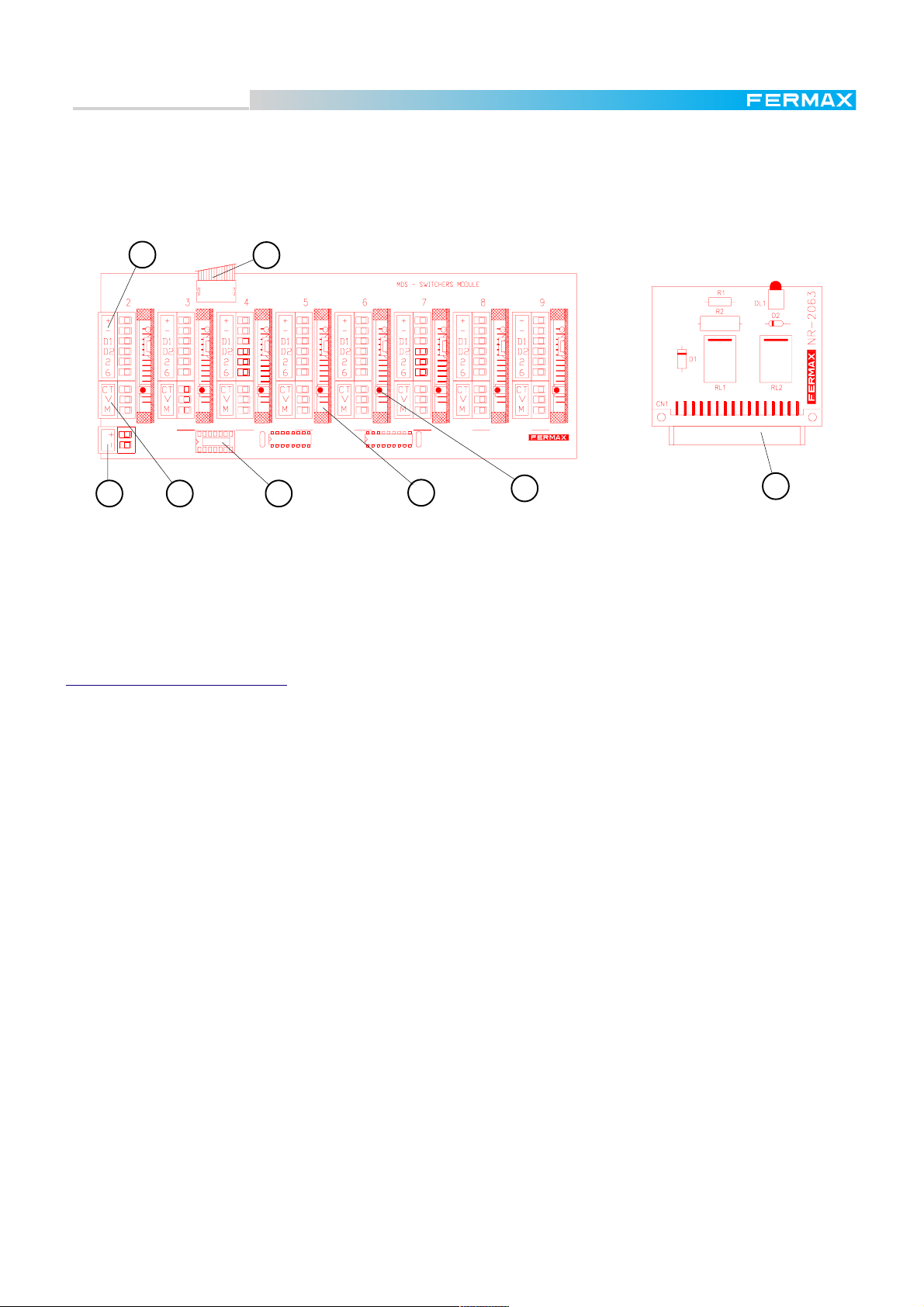
The only difference between Ref.2420 and Ref.2421 is that the Ref.2421 includes an MDS-SWITCHER
MODULE, represented in the figure below, which is connected to the NR-2055 Module by means of a flat
cable, extending the capacity of 2 audio/panels (Ref.2420) up to a maximum of 10.
This MDS-SWITCHER MODULE allocates up to 8 Switcher Cards, which are inserted in the slots (see
figure).
2
1
3 4 5
SWITCHERS BASE MODULE
1. Flat cable from the Central Unit.
2. Panel connector.
3. Power supply connector.
4. Video connector.
5. Switcher extension socket.
VERY IMPORTANT NOTES:
* The two panels connected to the NR-2055 card do not need Switcher Cards, since the NR-2055 already
includes them, but use one switcher card for each outdoor panel you have to connect into the MDSSWITCHER MODULE (Panel connectors 2 to 9) inserting it into the corresponding slot beside the connector.
* Configure the corresponding panel number matching with the panel number connector in which it has
been inserted. Se pages 22 to 25.
* Access control panels can be connected to any panel connector. They can be connected even directly to
any other panel already installed. Do not need switcher card, but it is neccessary to configure its dipswitches
with a panel number not used by any other panel in the same central unit.
* Use Panel 1 connector for the first outdoor panel and reserve Panel 0 connector for the second outdoor
panel (if there is one), Guard Unit or FXL (if the Central Unit is linked to others).
* In FXL installations, Panel 0 is always reserved for the FXL audio communication.
6
7
SWITCHER CARD REF.2422
6. Switcher Card (inserted into their slot).
7. Status led indicator. It is on while the
corresponding audio panel is in use
8. Switcher Card socket.
8
* J1 to ON position directly enables audio between Panel 1 and the decoder bus. Therefore, by inserting a
telephone handset in the test connector of any decoder it is possible to have check audio with the outdoor
panel. This feature is useful when checking or programming the system. The same happens for J0 (with
Panel 0). Whenever these jumpers are set to ON, the corresponding LED (P0 or P1) are on. The LEDs are
also activated when the Central Unit enables the outdoor panel. Do not forget to put J0 or J1 back to its
normal (OFF) position, after checking.
Equivalent LEDs are placed in the Switcher cards to indicate audio activated. The difference is that these
cards do not have activation jumper
* SW1-2 PC TEST MODE has to be put to ON position only when the Decoder PC Intercace Ref. 2466 is
being used, to program decoders or to check the system.
Note that system is then blocked and display shows the message "In Maintenance".
* In case the system is working as Digital Controller, SW1-3 is used to enable the PIN CODE feature. Permission
to open the door is then controlled by means of the PC programming. See PC Programming Manual for
further details.
Pag. 16
Page 17
Technical Book
MDS
MDS
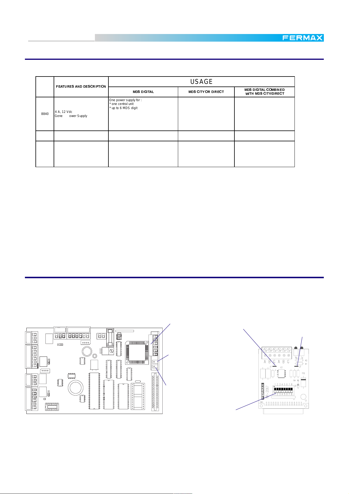
MDS Power Supplies
The following power supplies are suitable for MDS systems:
)($785(6$1''(6&5,37,21
REF.
4 A, 12 Vdc
8840
General Power Supply
4 A, 18 Vdc
8830
Video Power Supply
0,75 A, 12 Vdc
8837
(with build-in battery)
Auxiliary Power Supply
0'6',*,7$/ 0'6&,7<25',5(&7
One power supply for :
* one central unit
* up to 6 MDS digital panels
* up to 120 decoders. See note below.
To recuperate the droping voltage along the
bus decoder (see page 9).
One power supply every 60 monitors . See
note below.
To recuperate the droping voltage along the
bus decoder (see page 9)
USAGE
One power supply every 60 monitors.
See note below.
One power supply for every MDS
DIRECT/CITY panel and up to 40
decoders. See note below.
0'6',*,7$/&20%,1('
:,7+0'6&,7<',5(&7
One power supply for :
* one central unit
* up to 6 MDS digital panles
* up to 120 decoders. See note below.
To recuperate the droping voltage along
the bus decoder (see page 9).
One power supply every 60 monitors.
See note below.
One power supply for:
* one MDS DIRECT/CITY panel
* up to 40 decoders. See note below.
To recuperate the droping voltage along
the bus decoder (see page 9).
Note
* The number of decoder that can be supplied by the same power source depends on the wire section used
and the distance between them, as long distances and thin wires increase the resistance.
See page 9 for the dependence between the distance and the maximum number of decoders that can be
supplied with the same power supply.
For the same reason, the number of monitors that can be supplied depends on the section and wire length.
60 monitors are estimated using the ref. 5919 FERMAX wire, and up to 300m. from the Power Supply up
to the last monitor.
* Using one emergency battery (Ref. 2070 or 2337)connected to each ref. 8840 Power Supply, the audio
system (not video) can work in the event of power failure. Autonomy is estimated at 40 minutes, but
depends on the use. Ref. 8837 Power Supply already includes an internal built-in battery.
FXL Network card ref. 2428
The way to connect several MDS-DIGITAL Central Units is by means of the FLX network (FERMAX LINK).
It is possible to link up to 64 Central Units. When the Central Units are linked, the maximum number of
Outdoor Panels per Central Unit will be 31, since the FXL CARD uses the PANEL 0 position. Each card
includes a set of microswitches to configure the following data (see switches table on next page)
PANEL 0
CT
V
M
+
SA
SB
2
6
PANEL 1
CT
V
M
+
SA
SB
2
6
PIN_PADSTACKPIN_PADSTACKPIN_PADSTACKPIN_PADSTACKPIN_PADSTACKPIN_PADSTACK
P1
SWITCHERS
CT
D1
M
D2
V
2
6
+
-
INPUT
DECODERS
+-
SW1
ON
1
32
MDS - BASE MODULE
A
B
G
A
B
G
FXL card inserted
in its connector
"Tx" LED. It blinks
while module is sending data to
the FXL.
"Rx" LED. It blinks while
this module is receiving data from
EXTENSION INTERFACE
the FXL.
Configuration switches
Notes:
* If the system has only two linked Central Unit cut both J1 and J2 only in the module installed into the first
Central Unit. This is to share the "pull up" and "pull down" resistances.
Jumper "J1" See note
Jumper "J2". See note
* If the system has more than two Central Units, cut both J1 and J2 in all the modules, except in one of them
installed in the middle of the system. This is to avoid excessive "pull up" and "pull down" resistances.
Pag. 17
Page 18
Technical Book
MDS
MDS
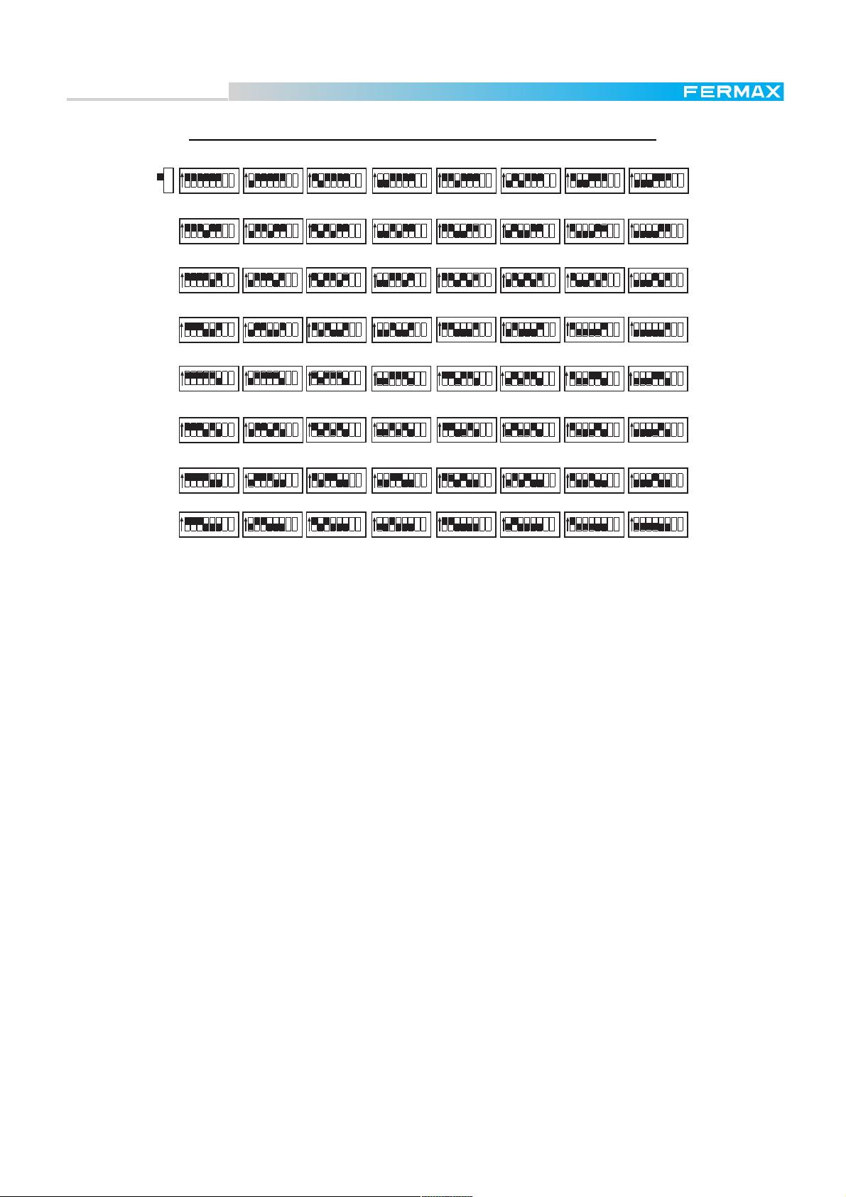
FXL CONFIGURATION SWITCHERS. CENTRAL UNIT NUMBER
ON ON ON ON ON ON
ON
5123 4 768 5123 4 768 512 3 4 768 5123 4 768 5123 4 768 5123 4 768
01 2 3 4 5
ON ON
5123 4 768 512 3 4 768
891011
ON
ON
5123 4 768
ON ON ON ON ON ON
5123 4 768 5123 4 768 5123 4 768 512 3 4 768 5123 4 768 512 34 768
12 13 14 15
5123 4 768
ON ON
5123 4 768 512 3 4 768
ON
ON ON
5123 4 768
ON ON
5123 4 768 5123 4 768
67
5123 4 768 5123 4 768
ON
5123 4 768
16 17 18 19 20 21 22 23
5123 4 768
ON
5123 4 768
ON
ON
5123 4 768
5123 4 768
ON
ON
5123 4 768
24 25 26 27 28 29
ON ON ON
5123 4 768 5123 4 768 5123 4 768
ON
32 33 34 35
ON ON
5123 4 768 512 3 4 768
40 41
ON
ON ON
ON ON ON ON
5123 4 768
48 49 50 51 52 53
5123 4 768 5123 4 768
ON ON ON ON ON
5123 4 768 512 3 4 768 5123 4 768 5123 4 768 512 3 4 768
42
5123 4 768 5123 4 768 5123 4 768 5123 4 768
ON ON ON ON ON
5123 4 768 512 3 4 768 512 3 4 768 5123 4 768 512 3 4 768
43 44 45 46 47
ON
56 57 58 59
5123 4 768
5123 4 768
ON
5123 4 768
36 37 38 39
60 61 62 63
ON
ON ON ON
ON
ON ON
5123 4 768
5123 4 768 5123 4 768
30 31
5123 4 768 5123 4 768 512 34 768
5123 4 768
ON ON
5123 4 768 5123 4 768
54
55
ON
5123 4 768
The microswitch "7" set to "OFF" (long call) indicates that it will first be necessary to dial the block number
in order to call the telephones (one or two digits) followed by the telephone number (four digits), when the
call is made from the general entrances. If the call is made from the corresponding block entrance only the
digits corresponding to the telephone number are required.
In the "ON" position (short call) it will not be necessary to enter the block number, but only the telephone
number, whether the call is made from the general entrance or from the block entrance.
Long call is necessary in places where the apartment numbers are repeated in two or more blocks, in order
to identify the block, when the call is made from the general entrance. Otherwise, short call is suitable.
The microswitch "8" set to "OFF" indicates that the panels installed in the central unit will be considered as
general entrances to a condominium (it enables calls to telephones controlled by other central units), while
in the "ON" position indicates that it is a central unit installed to manage a specific block.
Note: this treatment is different if we use the multistairs system provided by the MDS Version 3.1 or higher
(see page 25).
In Digital Controller Systems (SW1-3 in the central unit set to OFF) put microswitches 7 & 8 in the FXL card
to OFF to set the DC Extended Mode. It is then possible to link up to 64 central units which allows us to
manage up to 65.408 users). The total of accesses is limited to 31, as they are shared in all the central
units and access 0 is used (PANEL1) for the FXL network.
Examples:
* There is a condominium formed by 3 blocks, with apartments numbered from 101 to 150 in the first block,
from 201 to 250 in the second and from 301 to 350 in the third block.
We can use short call in this case, because there are no repeated apartment numbers. To call apartment
307 (in block 2) we will dial 3-0-7 either from the general entrance or from the block entrance.
* There is a condominium formed by 5 blocks. All of them have the apartments numbered from 1 to 150.
We have to use long call, because there are repeated apartment numbers in the blocks. To call apartment
25 in the 3º block, we will dial 3-0-0-2-5 if the call is made from the general entrance, and 2-5 only if the
call is made from the block entrance.
Pag. 18
Page 19

Technical Book
MDS
MDS
PC Interface Programming Card Ref. 2427
The MDS-Digital system parameters can be configured via PC, giving the possibility of programming the
system before installing it with all the advantages this provides: installations management (by files), user
lists... FERMAX has developed special software to manage and program the MDS-Digital systems: the
WINCOM. See the Basic and PC MDS Programming Manuals for further details.
By means of this card, it is also possible to change the language of the messages shown in the MDSDigital panel display.
PC card inserted in its
connector
RX led.
Central Unit receiving data from PC
TX led.
Central Unit sending data to PC
The cable required to link the PC with the PC Interface Card in Central Unit is not supplied by FERMAX.
You can easily make your own cable depending on the serial connector you want to use (DB9 or DB25).
PIN Nº: PIN Nº:
2
3
5
2
3
5
2427 Card sidePC side
DB-9
PIN Nº: PIN Nº:
2
3
7
MAX. 3m LENGTH
2
3
5
2427 Card sidePC side
DB-25
MAX. 3m LENGTH
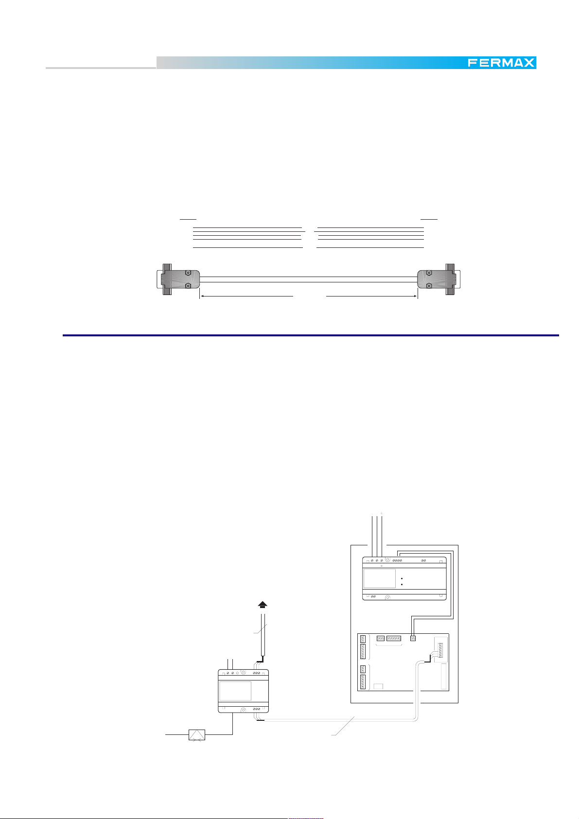
FXL Central Programming Module Ref. 2338
There is another choice for PC programming in MDS-Digital systems which is strongly recommended for
installations with several Central Units. In that particular case, it may be interesting to use a device that
allows the programmer to access every Central Unit from a common point, without it being necessary to
unplug the FXL card (as with the PC Interface Module above).
220 Vac220 Vac
PRIM.
REF. 8840
ALIMENTADOR
POWER SUPPLY
EF
V
M
+
-
SA
PANEL 0PANEL 1
SB
2
6
Ct
V
M
+
SA
SB
2
6
MVCt 6 2DD
DECODERS
+- -+
-+
21
MDS CENTRAL UNIT
WITH FXL INTERFACE CARD
-+
BAT.13.8V
12V
+-
A
B
G
A
B
G
NR-2067
NR-2055
STANDARD CITYMAX
TELEPHONE REF.8044
NR-2086
21 3 54 6
Ref.5922
220 Vac
PRIM.
REF. 2338
GESTION FXL
FXL MANAGEMENT
-
A
B2 662BA
1234 6
-
WINCOM
PC cable for FXL
Pwr
Rx
Tx
MANAGEMENT
Ref.5918Ref.5918
PRIM.
REF. 8840
ALIMENTADOR
POWER SUPPLY
FE
CtCt
V
M
+
SA
SB
2
6
Ct
V
M
+
SA
PANEL 1 PANEL 0
SB
2
6
MDS CENTRAL UNIT
WITH FXL INTERFACE CARD
+
--+
12V
DD26CtVM
12
DECODERS
NR-2055
+-
BAT.13.8V
-++A
B
G
A
B
G
NR-2067
Pag. 19
Page 20
Technical Book
MDS
MDS
The figure shown on the previous page illustrates how to connect the FXL Programming Module Ref.2338
in a typical installation with 2 Central Units. For installations with more Central Units, the device may be
connected at any point between them (there is no restriction regarding the central units it is connected
between).
This device allows us to use a BASIC CITYMAX TELEPHONE REF.8044 for communication with any
outdoor panel or guard unit (see figure).
The link cable required is shown below. This cable is not included with the module.
PIN Nº: PIN Nº:
1
2
3
4
5
6
7
8
9
BROWN
RED
ORANGE
YELLOW
GREEN
1
2
3
4
5
6
7
8
9
PC side
MAX. 3m LENGTH
2338 Module side
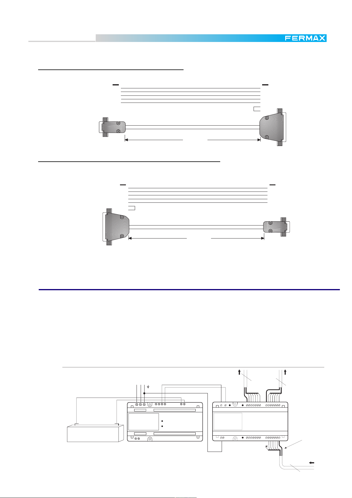
Remote Programming Module Ref. 2467
It is also possible to connect to a MDS system remotely, via modem. Then all the same features are
available as with local connection. For this, a PC with the Wincom software connected to the telephone
line via Modem is required. The link cable between the PC and the modem is represented on the next page.
On the MDS side are required:
* Ref. 2467 Modem FXL Access Terminal
* Ref. 2428 FXL Network Card to connect the Ref. 2467 to a single MDS central Unit or to a FXL network.
* A 56K U.S. Robotics Modem to connect the Ref. 2467 to the telephone line.
* A link cable to connect the Ref. 2467 module to the modem (See next page). This cable is not included
with the module.
220 Vac
M.D.S. CENTRAL UNIT
Ref.2420
DECODERS
12
NR-2055
12V+ --+
+ - BAT.13.8V
-++-DD26CtVM
NR-2067
A
B
G
A
B
G
FXL net
Shielded twisted pair
9-12 Vdc
+-CFG
ABG
REF. 2467
GESTION FXL-MODEM
MODEM FXL ACCESS
TERMINAL
RS-232 GBA
MODEM
TELEPHONE LINE Shielded twisted pair
PRIM.
REF. 8840
ALIMENTADOR
POWER SUPPLY
FE
Ct
V
M
+
SA
SB
2
6
Ct
V
M
+
SA
PANEL 1 PANEL 0
SB
2
6
Use the MDS Wincom software from the remote PC to connect and program the MDS System, as if it were
connected directly to them. See instructions included with the Ref. 2427 PC Card for further details.
Pag. 20
Page 21
Technical Book
MDS
MDS
Cable to connect the remote PC to the modem
PIN PIN
1
2
3
4
5
Jumper
8
3
2
20
7
4
5
PC side
MAX. 3m LENGTH
Remote modem side
Cable to connect the local modem to the Ref. 2467 module
PIN PIN
Local modem side
8
3
2
20
7
4
Jumper
5
MAX. 3m LENGTH
1
2
3
4
5
Ref. 2467 module
56K U.S. Robotics Modem is recommended in both cases, for local and remote connection.
MDS Repeater Module Ref. 2339
Due to technical limitations, communications are not possible between Central Unit and decoder, panels or
FXL card more than 1200m away. For this reason, if longer distances are to be managed, the MDS Repeater Module REF.2339 will be required.
MDS repeater can be used in the decoder bus (most common application), but also between Central Unit
and the outdoor panels or even between FLX cards.
MDS Repeater Module is also used for splits and/or branches in the installation. It is convenient to install a
power supply beside it, Ref.8840 or Ref.8837. If this module is used, see instruction manual for further
details.
Ref.5918
HTL 6G2B
-+
BA
A
2
Ref.5918
2-+6G-BA
+-
A6G
+
6B2 G
SHIELD
+
REF.2070
85 : 270 Vac
-
REF.8840
ALIMENTADOR DIGITAL
POWER SUPPLY
E F
-+-+-+
13.8V BATERIA12 VDC220 VPRIM
REF.8840 REF.2339
+ -
REF. 2339
REPETIDOR MDS
MDS REPEATER
GG LT H
Pag. 21
Page 22
Technical Book
MDS
MDS
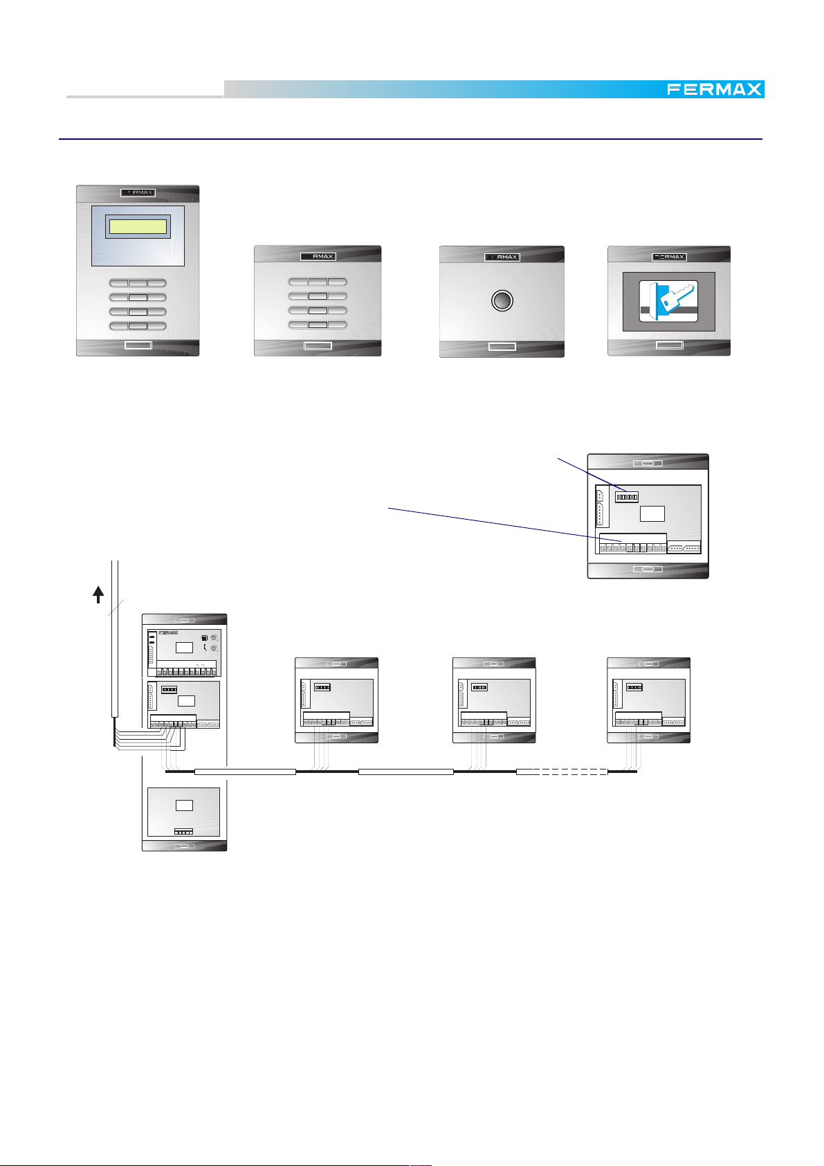
MDS DIGITAL PANELS
The different panels that can be used in a MDS Digital system are:
MDS Outdoor panels
There are two references:
Ref. 87711: Audio MDS digital panel
Ref. 87701: Audio & Video MDS Digital Panel
1
6
LCD DIGITAL SYSTEM
123
456
789
A0 B
87711 Front view
PLACA MDS DIGITAL AUDIO
MDS DIGITAL AUDIO PANEL
F U
3 2 1
AMPLIFICADOR UNIVERSAL
UNIVERSAL AMPLIFIER
Cp1
COD.98589
1
2
3
6
L+
L-
Cp2
1
32 6
CN1
AbAb Tc
7
1
HIGH RESOLUTION
CCD CAMERA
PAN &TILT
2
2
LCD DIGITAL SYSTEM
3
1. Speaker grille.
2. Digital display.
3. Search keys.
4. Bell button.
5. Keypad.
6. Lens.
7. Infrared light.
3
4
4
5
8
9
Cp1
123
456
789
A0 B
87701 Front view
PLACA MDS DIGITAL VIDEO
MDS DIGITAL VIDEO PANEL
F U
3 2 1
AMPLIFICADOR UNIVERSAL
UNIVERSAL AMPLIFIER
Cp1
COD.98589
1
2
3
6
L+
L-
Cp2
1
32 6
CN1
Ab Ab Tc
TELECAMARA
REF.8028
5
8. Speaker volume control.
9. Microphone volume control.
10. Pan and tilt
11. Dipswitch configuration.
8
Cp1
9
CAMERA
+, -: /Video supply (18 Vdc).
CT: Camera activation.
V, M: Video output (COAX).
Pag. 22
CN8 SW1
ON
+
-
Cp
1
2
3
CN5
6
Tc
Ab
+
-+
REF. 87711
87654321
DISPLAY DIGITAL
MDS
CITY LINE
COD.98227
Sb
-
26 SB
TECLADO
DIGITAL MDS
CITY LINE
COD.98208
CN3
Dt
-+
ABCD
Sa
11
CN2
-CkABCD
Back view and internal wiring
CT VM
+
-
..........
..........
CN8 SW1
ON
+
-
87654321
Cp
DISPLAY DIGITAL
1
2
3
6
Tc
Ab
+
MDS
CITY LINE
CN5
COD.98227
Sa
Sb
26 SB
-+
TECLADO
DIGITAL MDS
CITY LINE
COD.98208
-
REF. 87701
....
....
LCD/CONTROLLER
2: Audio from Telephones-Monitors
to Panel.
10
11
CN3
CN2
Dt
-+
-CkABCD
6: Audio from Panel to Telephones-
Monitors.
Ab, +: Electric lock control (12 Vdc 500mA
max).
-, B: Exit button.
-, S: Door Open detector.
ABCD
KEYPAD
-,D,C,B,A: Keypad control.
Page 23
Technical Book
MDS
MDS
MDS Digital Access control panels
The following access panels are also available:
LCD DIGITAL SYSTEM
123
456
789
A0 B
Ref. 23241
MDS Digital Keypad
w/display
MDS Digital Keypad
123
456
789
A0 B
Ref. 23411
Ref. 23261
MDS Button Reader
All of them are configured the same way as the other panels (microswitches).
Configuration
microswitches
Wiring connections
+, -: supply (12 Vdc)
Ab, +: electric lock, if required (12 Vdc, 0,5 A max.)
2, 6: not used in access control panels.
TO THE CENTRAL
UNIT
REF.5918
F U
3 2 1
Cp1
1
2
3
6
L+
L-
1
CN1
CN8 SW1
+
-
Cp
1
2
3
CN5
6
Tc
Ab
+
PANEL 0
AMPLIFICADOR UNIVERSAL
UNIVERSAL AMPLIFIER
COD.98589
Cp2
AbAb Tc
32 6
ON
87654321
DISPLAY DIGITAL
MDS
CITY LINE
COD.98227
Sa
Sb
26 SB
-+
Cp1
CN3
Dt
-+
-CkABCD
Sa, Sb: data input
B: exit pushbutton
CN2
PANEL 1 PANEL 2 PANEL 31
CN8 SW1
ON
+
-
Cp
1
2
3
CN5
6
Tc
Ab
+
87654321
CN3
Sa
-+
CN2
Sb
26 SB
Dt
-+
-CkABCD
CN8 SW1
ON
+
-
Cp
1
2
3
CN5
6
Tc
Ab
+
87654321
CN3
Sa
-+
CN2
Sb
26 SB
Dt
-+
-CkABCD
ACCESS
PROXIMITY READER
CONTROL
Ref. 23351
MDS Proximity card Reader
CN8 SW1
ON
+
-
87654321
Cp
1
2
3
6
Tc
+
CN5
Ab
Sa
-+
CN8 SW1
ON
+
-
Cp
1
2
3
CN5
6
Tc
Ab
+
LECTOR LLAVE
BOTON
CITY LINE
COD.98131
CN3
Sb
26 SB
87654321
Sa
Sb
26 SB
-+
CN2
Dt
-+
-CkABCD
CN3
CN2
Dt
-+
-CkABCD
TECLADO
DIGITAL MDS
CITY LINE
COD.98208
ABCD
-
M.D.S. AUDIO PANEL REF.87711
notes:
* There is also a Secondary MDS Button Reader Ref. 23262 and a Secondary Proximity card Reader Ref.
23352, which do not have internal controller, but they can be connected to any Keypad Access Panel, via
CN2 connector. Then the system, if it has been properly programmed, will require a PIN code through the
keypad acces after the tag has been presented to the secondary panel. No configuration is required for the
secondary panel, since it uses the same controller as the Keypad to which it is connected. See PC MDS
Programming Manual for further details.
* As with the outdoor audio and video panels, the access panels have to be configured with a number not
repeated in any other panel in the same central unit.
* In contrast with the audio panels, access panels can be connected in any PANEL slot in the central unit.
They can also be connected to any outdoor panel or any other access panel in the system indeed. See
diagram above.
Pag. 23
Page 24
Technical Book
MDS
MDS
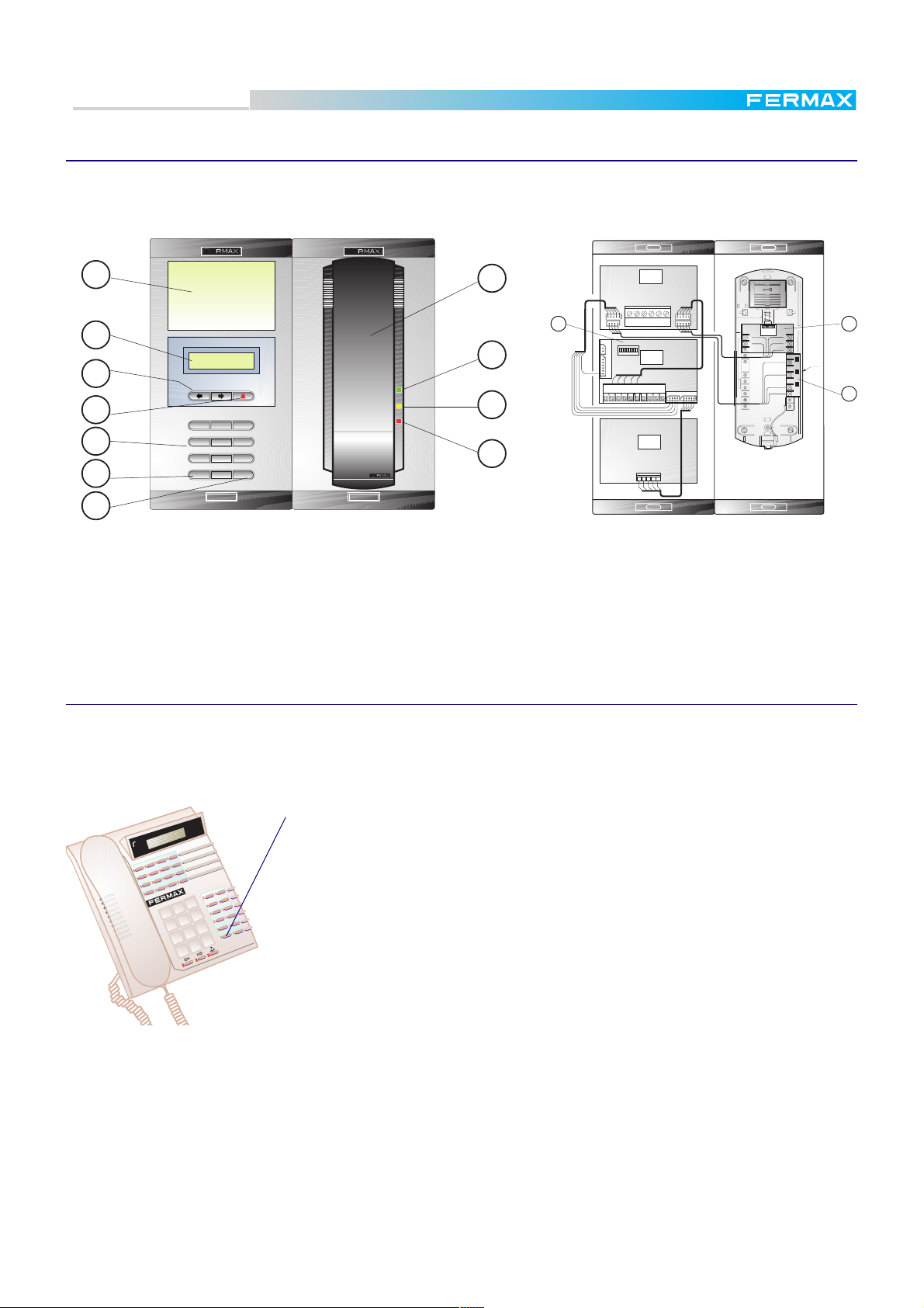
MDS Wall Guard Unit panel
The MDS Wall Guard Unit is composed of two parts, the MDS Porter/Guard Telephone and the MDS Porter/
Guard Module supplied separatelly, which must be assembled and wired as represented below.
AMPLIFICADOR
CONSERJE MDS
1
8
CITY LINE
COD.98337
CN3
SA2SB
2
12 13
9
3
4
5
6
LCD DIGITAL SYSTEM
123
456
789
A0 B
10
11
CN5
CN8 SW1
ON
+
-
Cp
1
2
3
CN5
6
Tc
Ab
+
-+
+ -
DISPLAY DIGITAL
87654321
COD.98227
Sa
Sb
26 SB
TECLADO
DIGITAL MDS
CITY LINE
COD.98208
-
CN4CN2
CN1
6
MDS
CITY LINE
CN3
CN2
Dt
-+
-CkABCD
ABCD
NR-0208
COD.98247
1
2
3
4
5
6
NR-1917
AMARILLO/YELOW
NARANJA/ORANGE
ROJO/RED
NR1917
MARRON/BROWN
14
7
REF.87721 REF.87731
Front view
1. Information Window.
2. Digital display.
3. Search keys.
4. Call button (bell).
5. Keyboard.
6. Erase and select stored calls key.
7. Confirmation key.
8. Guard Telephone.
9. Green Button, (see Users Manual).
10. Yellow Button, (see Users Manual).
11. Red Button, (see Users Manual).
12. Configuration Switches.
13. Telephone PCB.
14. Telephone buttons PCB.
Back view and internal wiring
MDS Desktop Guard Unit
This Guard Unit has the same features as the wall mounted one. It does not need to be assembled.
Since it does not have configuration microswitches, Panel Number configuration process is different. See
below.
Press this button ( the lower on the left keys row) for a while (5 seconds), to enter the panel
number.
* Display will show "?", requesting a panel number
* Enter the corresponding panel number (between 0 to 9).
3
2
1
6
5
4
9
8
7
#
B
0
*
A
Note that this panel number shall match the one in which the guard unit is conected.
From factory, the guard unit is programmed as panel 0.
Further information about programming, features and use are included with the guard
unit.
Notes
* The guard units can work in one of several modes NIGHT, DAY or MIXED, TRANSFER-DAY, TRANSFER
MIXED and MASTER, depending on how the corresponding central unit has been configured. This can
only be changed by means of a central unit connected to it. Each of these modes and how to change them
is explained in the Operating Instructions that come with the Guard Unit.
* Guard units can be configured to manage "normal" calls from dwellings but also "panic" calls. In addition,
the system can be configured for one or more guard units to receive "alarm" messages. See the PC MDS
programming Manual.
* Entering programming mode you can know in which mode a central unit (and every central unit connected
to the FXL) is working. See the Basic MDS Programming Manual for further details.
Pag. 24
Page 25
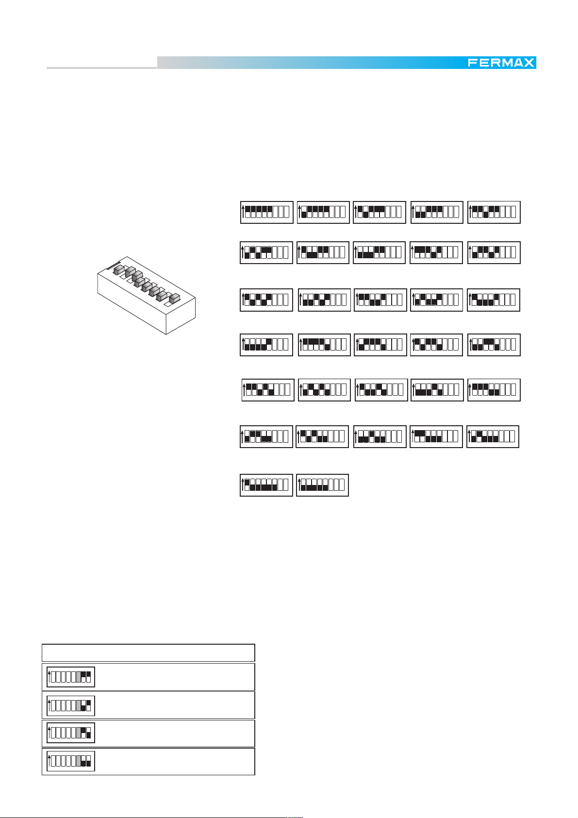
Technical Book
ON
4
512 3 4 768
ON
ON ON
512 3 4 768
512 3 4 768 512 3 4 768
5
67
ON
8
512 3 4 768
ON
512 3 4 768
9
ON ON
512 3 4 768 512 3 4 768
10 11
ON ON ON
12 13 14
512 3 4 768 512 3 4 768 512 3 4 768
ON
15
512 3 4 768
ON
24
512 3 4 768
ON
ON
ON
25 26 27
512 3 4 768
512 3 4 768
512 3 4 768
ON
ON
28 29
512 3 4 768
512 3 4 768
ON ON
ON ON ON
01 2 3
ON
512 3 4 768 512 3 4 768 512 3 4 768 512 3 4 768
ON
ON ON
ON
20 21 22 23
512 3 4 768
512 3 4 768 512 3 4 768
512 3 4 768
16 17 18 19
ON
ON
ON ON
512 3 4 768
512 3 4 768
512 3 4 768 512 3 4 768
30 31
512 3 4 768 512 3 4 768
MDS
MDS
Codification of the microswitches located on the back side of the display of the MDS Audio/Video and Wall
Guard Unit panels must be carried out.
These microswitches must be configured depending on the corresponding panel number and other features of the installation. See tables below.
In the case of the Desk Top Guard Unit, there are no programming microswitches, so the programming process is explained in the drawing on the previous page.
ON
1 2 3 4 5 6 7 8
VERY IMPORTANT NOTES:
* Make sure that there are no repeated panel numbers between those connected to the same central unit.
* The audio panels must be connected in the central unit to the slot number corresponding to
the configured panel number. This is not neccessary in the case of the access control panel, which can
be connected to any other panel and any Panel nº connector as well.
* Remember that, in FXL configurations, Panel 0, in each central unit, is reserved for audio by FXL network.
Microswitches 6, 7 and 8 have function only in Audio/Video MDS Panels, but not in Guard Units. The
meaning is as follow:
CODIFICACION/SETTING
ON
ON
ON
ON
512 3 4 768
512 3 4 768
512 3 4 768
512 3 4 768
Tiempo apertura Abrepuertas
Electric lock operating time
1 Segundo
1 Second
4 Segundos
4 Seconds
7 Segundos
7 Seconds
11 Segundos
11 Seconds
* Microswitch 6 (only function in multistairs configuration)
See page 5.
Meaning, in this case:
ON: Panel used as block
OFF: Panel used as general entrance
Pag. 25
Page 26
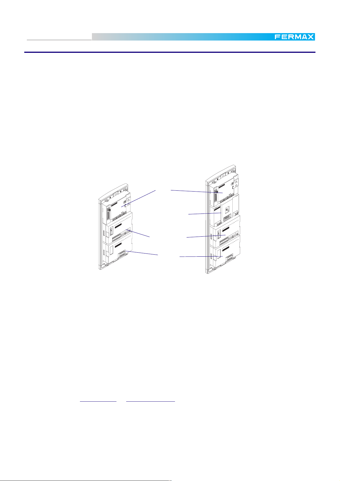
Technical Book
FERMAX
FERMAX
C
p
2
C
p
1
A
b
A
b
T
c
6
3
2
1
+
D1
D2
-
D
-
+
-
2
6
B
C
B
A
MDS
MDS
MDS DIRECT PANELS
The equipment defined in the MDS DIRECT system is the MDS Direct Audio Panel Ref. 2460 & MDS
Direct Video Panel Ref. 2461 for Audio or Video installations respectively (see figures below).
The MDS-DIRECTs main improvement, compared with the MDS-DIGITAL system, is that the outdoor
panels can work without any central unit.
The MDS-DIRECT can be combined with MDS-DIGITAL systems, giving the possibility of working as panel
in the internal blocks, providing the MDS DIGITAL panels for the general entrances.
Another possibility is combining MDS-DIRECT with MDS-CITY or even other MDS- DIRECT panels. In this
case one MDS DIRECT works as general entrance, while the MDS-CITY or other MDS DIRECT as internal
block entrances. See features figures and table on pages 4 and 5.
It is possible to program up to 100 access codes to allow the users to enter the building.
See the included technical information for further details.
Cp1
Tc
b
A
b
A
Cp2
6321
AX
FERM
B
6
2
2
D
D1
-
+
-
+
FERMAX
A
B
C
D
-
Telecamera (not
VERY IMPORTANT NOTES
In condominiums with several blocks, remember when programming the DECODERS:
* That the 2 first digits of the numbers assigned to each decoder (house number) must coincide with the
Interior Block number previously assigned to the MDS CITY or MDS DIRECT Panel to which they are
connected.
For example: B B A A, with BB being the block number (one or two digits, from 00 to 99) and AA the
apartment number (two digits, from 00 to 99).
- Apartment number 1 of Block 1, will be programmed in the Decoder as: 101
- Apartment number 2 of Block 1, will be programmed in the Decoder as: 102
- Apartment number 1 of Block 23, will be programmed in the Decoder as:2301
- Apartment number 13 of Block 45, will be programmed in the Decoder as:4513
The block number must also be programmed in the corresponding Interior Block panel. See "Digitizer
Instructions" for MDS CITY Panels or "Instruction Manual" included with the MDS DIRECT panel.
* Then, a call must be made from the general entrance using the digits corresponding to the block number
+ the digits corresponding to the apartment number.
General Entrance-->block number + apartment number
* If the call is made from the Interior Block panel, only two digits (the ones corresponding to the apartment
number) are required.
E.g., To call the apartment number 19 in block number 7.
From the General Entrance Panel, key in 719
From the Block Panel, if MDS DIRECT, key in the number 19. The "7" is automatically inserted by the panel.
In MDS CITY, push the desired button (codified as 19 with the Call Extension Module, in this example).
Pag. 26
Amplifier
MDS DIRECT
MDS Direct Video Panel Ref. 2461
Back view
Keyboard
Page 27
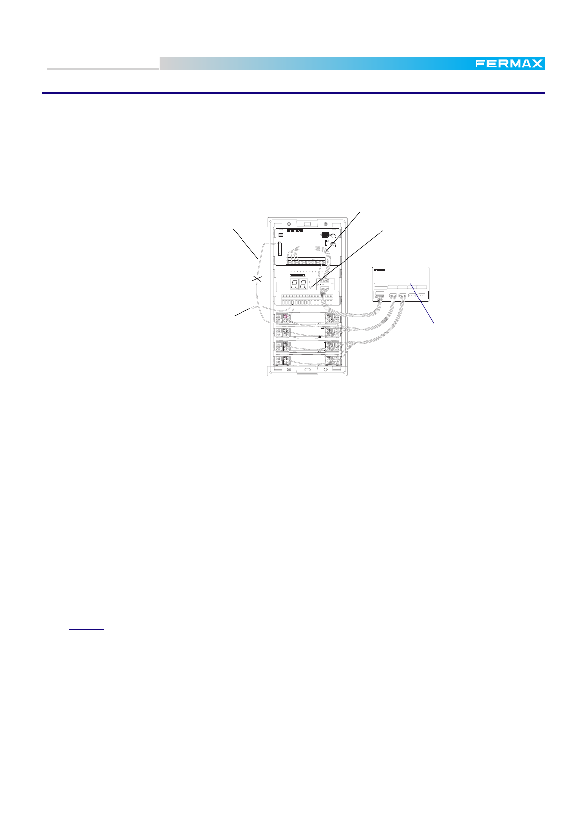
Technical Book
MDS
MDS
MDS CITY PANELS
Basically these are standard City panels, but provided with a Digitizer Module Ref. 2440, which being
mounted in a window, allows the panel to be used with MDS systems, and one or more Extension Call
Modules Ref. 2441 or Ref. 2442 that convert each pushbutton action into a digital signal acknowledged by
the digitizer.
As the size of the panel depends on the number of apartments (pushbuttons), this system is convenient
only for combined MDS systems, to be installed in internal blocks with a few apartments only. In any other
case (internal blocks with more than 20 or 30 apartments) MDS Direct panels are recommended.
Wiring detail from
Original Cp1
Connection to the
FU
PT1
3
2
1
PT2
AMPLIFIER
CN1
Ab
Cp2
Ab
6
P
S
2112
+-+- DD26+ DD CtS
-
EXT.
INT.
Cp1
Tc
Digitizer
PACK EXTENSION 16 LLAMADAS
REF.2441
16 EXTENSION CALL PACK
SIGUIENTE/NEXT
1
ANTERIOR/PREVIOUS
LLAMADAS/CALLS
4327651098 1211 151413 16
Call Extension Mo
VERY IMPORTANT NOTES
In condominiums with several blocks, remember when programming the DECODERS:
* That the 2 first digits of the numbers assigned to each decoder (house number) must coincide with the
Interior Block number previously assigned to the MDS CITY or MDS DIRECT Panel to which they are
connected.
For example: B B A A, with BB being the block number (one or two digits, from 00 to 99) and AA the
apartment number (two digits, from 00 to 99).
- Apartment number 1 of Block 1, will be programmed in the Decoder as: 101
- Apartment number 2 of Block 1, will be programmed in the Decoder as: 102
- Apartment number 1 of Block 23, will be programmed in the Decoder as: 2301
- Apartment number 13 of Block 45, will be programmed in the Decoder as: 4513
*The block number must also be programmed in the corresponding Interior Block panel. This can be done
from an MDS DIRECT panel, from an MDS Digital Central Unit or even from a PC, using the Decowin program.
See the corresponding technical information for each one.
*Then, a call must be made from the general entrance using the digits corresponding to the
number + the digits corresponding to the apartment number.
General Entrance-->block number + apartment number
* If the call is made from the Interior Block panel, only two digits (the ones corresponding to the apartment
number) are required.(MDS DIRECT panels). In MDS CITY, push the required button.
E.g., To call the apartment number 19 in block number 7.
From the General Entrance Panel, key in 719.
From the block panel in MDS CITY, press the button to which the call wire nº 19 from the Call Extension
has been connected. If it is an MDS DIRECT panel, we simply key in the apartment number 19. The "7"
is added automatically by the Interior Block panel.
Every call wire from the Call Extension must be connected to the corresponding pushbutton
number (apartment number).
*For installations with several MDS-CITY panels to the same block, all the call extension
modules must be wired in the same order.
The number printed in each output in the Call Extension Module calls must match the
apartment number.
block
To connect several Call Extension Modules, see following page.
Pag. 27
Page 28
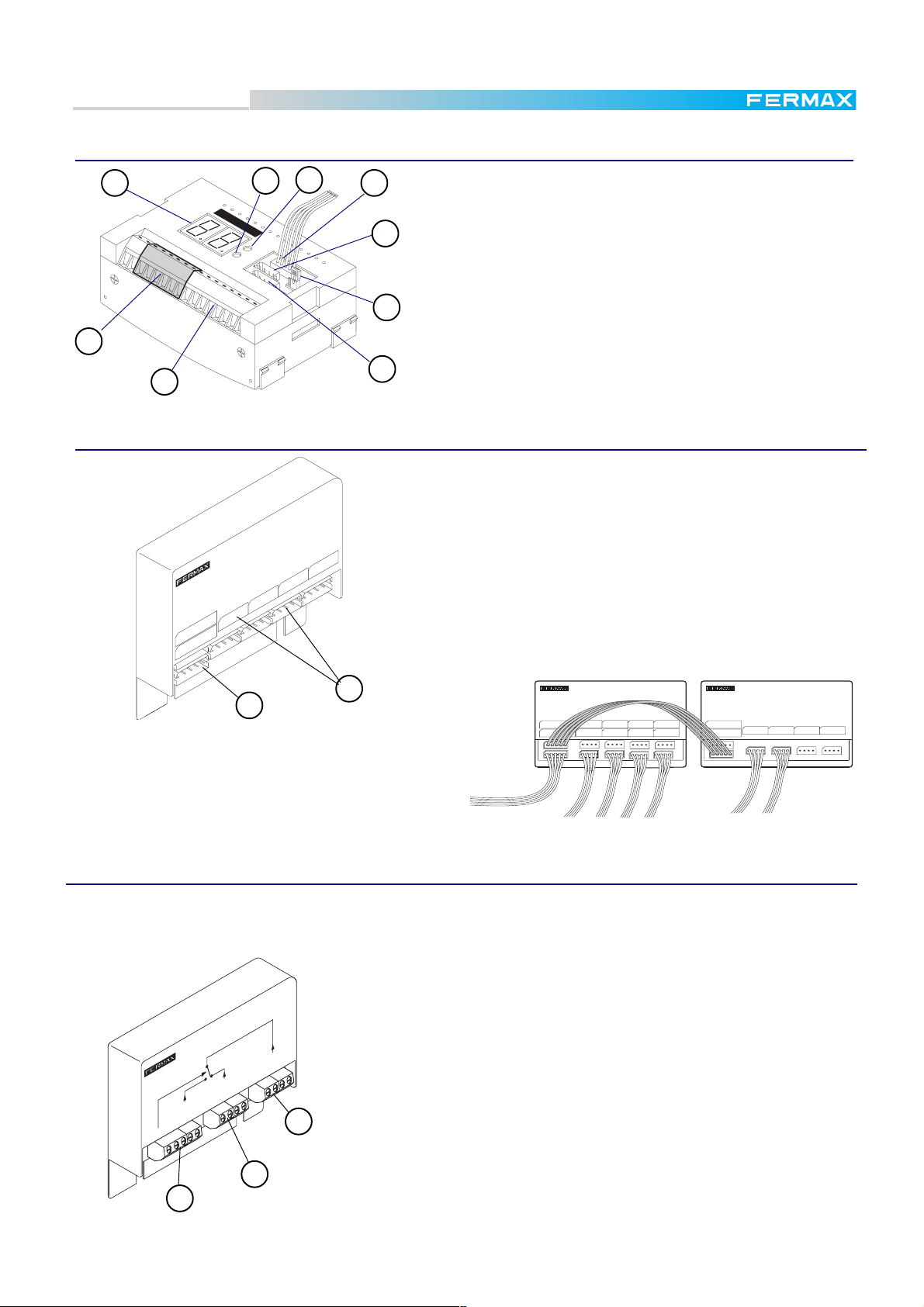
Technical Book
MDS
MDS
Digitizer Module Ref. 2440
4
FERMAX
S
2
Ct
3
6
5
P
7
2
+-
+-
1
DD
2
+-
DD2662
1
1
8
9
Call Extension Pack Ref. 2441 & Ref. 2442
PACK EXTENSION 16 LLAMADAS
16 EXTENSION CALL PACK
43
2
1
LLAMADAS/CALLS
6578 101191312 1614 15
REF.2441
SIGUIENTE/NEXT
ANTERIOR/PREVIOUS
1. Input terminals. Connections from the MDS bus decoder of
the MDS Central Unit or from previous MDS DIRECT panels.
2. Information display. Shows the programming stage.
3. Select button. To select programming optgions
4. Programming button. To program the digitizer parameters.
5. PC link connector. To program the digitizer from a PC
6. Amplifier connector
7. J1. Allows direct contact from the panel with telephones in
(ON).
8. Call Extension module connector
9. Output terminals.Connections to the next panels or MDS Di-
rect/City or Decoders.
The 16- and 32-call Extension Packs (Ref. 2441 and Ref.2442
respectively) are necessary in MDS CITY Panels. They are
used as intermediaries between the normal City pushbuttons
and the MDS system.
In panels with more than 32 buttons, several interconnected
Packs must be used.
1. Links connector Connections to the Digitizer or to other Call
Extension Pack.
2. Call connectors Connections to the pushbuttons in panel.
2
1
When several Call Extension Packs are linked to-
REF.2442
SIGUIENTE/NEXT
ANTERIOR/PREVIOUS
PACK EXTENSION 32 LLAMADAS
32 EXTENSION CALL PACK
LLAMADAS/CALLS
5
876
1
432 1091211 272625 28191817 20
313029 32232221 24151413 16
REF.2441
SIGUIENTE/NEXT
ANTERIOR/PREVIOUS
PACK EXTENSION 16 LLAMADAS
16 EXTENSION CALL PACK
LLAMADAS/CALLS
1
43276510981211 151413 16
gether, the second one starts to count from the last
number in the previous one. In the example shown
right, the second Pack (on the right) controls
pushbuttons from 33 to 48.
MDS Swticher Module Ref. 2443
For MDS-CITY and MDS-DIRECT systems (or combinations). In Video installations the system requires one MDS
City/Direct Switcher Module Ref. 2443 for every additional panel, i.e.: an installation with 8 Video panels to the
same block would require seven MDS Switcher Modules.
REF.2443
S
VIDEO PLACA
PANEL VIDEO
PACK CAMBIADOR VIDEO MDS
MDS VIDEO SWITCHER PACK
VIDEO EXTERIOR
EXTERNAL VIDEO
V
SALIDA VIDEO
VIDEO OUTPUT
Vi
Vo
1
1. VIDEO-OUT to Monitors or next switcher.
2. VIDEO-IN 1 Incoming Video from Main Panel 1.
3. VIDEO-IN 2 Incoming Video from Panel 2.
Pag. 28
2
3
Page 29
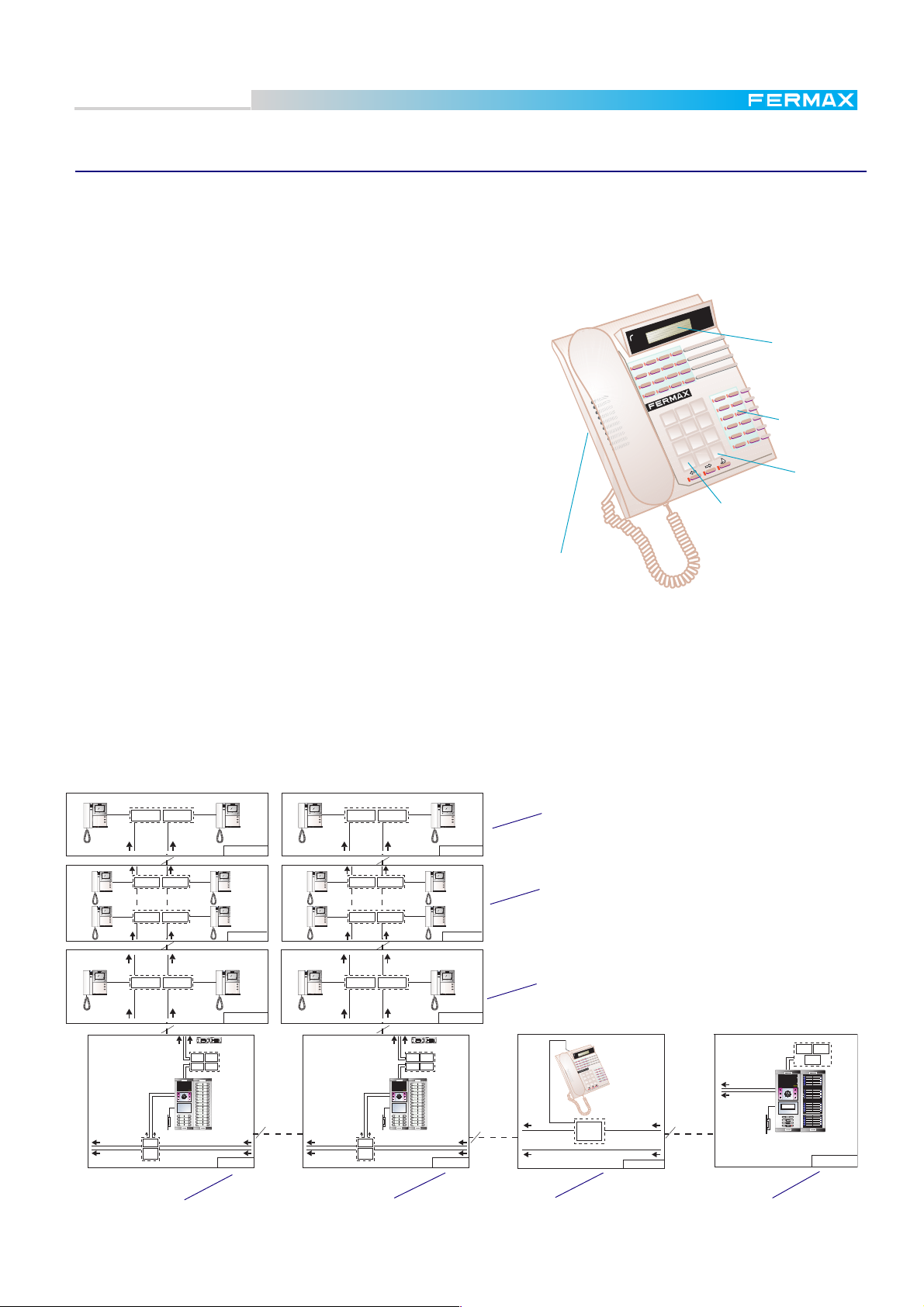
Technical Book
MDS
MDS
MDS City/Direct Guard Unit Ref. 2462
Generally, the MDS City/Direct Guard Unit offers 3 different operating modes: Day Mode, Mixed Mode and Night
Mode.
Both in Day and Mixed modes, it is possible to call all the telephones and/or panels from the guard unit. In Night
mode it functions as a MDS Direct panel.
As for reception of calls, the differences between different modes are:
In NIGHT mode the Guard Unit does not receive any calls but can
make them. In door entry phone installations it works as a General
Entrance panel.
In this mode, the display shows the usual instructions Dial Flat
Number and press %.
Informative
Display
In DAY mode every call from panels are captured by the guard
unit. From telephones and/or intercom panels it is possible to call
the guard.
A D character is shown on the top-left corner of the display.
In MIXED mode the calls from panels to telephones are not captured
by the guard unit, but the guard unit can be called from telephones
normally and from the panels just by pressing "%".
3
2
1
6
5
4
9
8
7
#
B
0
*
A
"Hotkeys"
keypad.
Accept
Call Stack
selecction
In the upper left corner of the display the letter "X" is visible.
Incoming call
volume
Further details come with the Guard Unit.
Example:
General entrance with 1 MDS DIRECT Video and MDS DIRECT/CITY Guard Unit in 2 Interior Blocks with
1 MDS CITY Video Panel in each one.
* Remember that you can generate your own specific installation with the Thumbnails and that all their
corresponding wiring diagrams are included in the annex. (See next page: "BLOCK DIAGRAMS AND
THUMBNAILS").
HIGH RESOLUTION
FLAT MONITOR
1
2
REF.2424REF.2418
REF. 5918 + REF. 5919
HIGH RESOLUTION
FLAT MONITOR
1
2
HIGH RESOLUTION
FLAT MONITOR
1
2
REF.2418
REF.2418
REF.2424
REF.2424
REF. 5918 + REF. 5919
HIGH RESOLUTION
FLAT MONITOR
1
2
MDS 4C
HIGH RESOLUTION
FLAT MONITOR
1
2
HIGH RESOLUTION
FLAT MONITOR
1
2
MDS 4B
HIGH RESOLUTION
FLAT MONITOR
1
2
REF.2424REF.2418
REF. 5918 + REF. 5919
HIGH RESOLUTION
FLAT MONITOR
1
2
HIGH RESOLUTION
FLAT MONITOR
1
2
REF.2418
REF.2418
REF.2424
REF.2424
REF. 5918 + REF. 5919
HIGH RESOLUTION
FLAT MONITOR
1
2
MDS 4C
HIGH RESOLUTION
FLAT MONITOR
1
2
HIGH RESOLUTION
FLAT MONITOR
1
2
MDS 4B
Monitors installed on top floor
Monitors installed on middle floors
HIGH RESOLUTION
FLAT MONITOR
1
2
REF.2424REF.2418
REF. 5918 + REF. 5919
HIGH PERFORMANCE
MULTIPLEXED DIGITAL SYSTEM
STOP
REF.2448
REGLETA
DE
EMPALME
REF.8830
REF.2443
ACCESO 1
HIGH RESOLUTION
FLAT MONITOR
MDS 4A
+
-
2-6
-+
D2
D1
V
-
BUS
BUS
DISTRIBUIDOR VIDEO
DECODER DE AUDIO 4
MADE IN SPAIN
MADE IN
V
-
4 SALIDAS
AUDIO DECODER 4
REF.2418
REF. 2424
CORTAR
DECODER N§:
PUENTE
DISTRIBUIDOR VIDEO
34
TELEFONOS /
TELEPHONES
VIDEO DISTRIBUTOR
PGM
VIDEO 4
VIDEO 2VIDEO 3
VIDEO 1
1
BUS
VIDEO 3
VIDEO 2
VIDEO 1
VIDEO 4
BUS
+
+
-
+
+MV- -
-
M+-VM
V
MV
MV M
V
D1
D2
+
412632316443312
62434
21
6
62
REF.8840
REF.2070
MDS 25U
Block 2 with one Access
1
2
REF. 5918 +
REF. 5919
HIGH RESOLUTION
FLAT MONITOR
1
2
REF.2424REF.2418
REF. 5918 + REF. 5919
HIGH PERFORMANCE
MULTIPLEXED DIGITAL SYSTEM
REF.2448
REGLETA
DE
EMPALME
STOP
ACCESO 1
REF.8830
REF.2443
HIGH RESOLUTION
FLAT MONITOR
MDS 4A
+
-
2-6
-+
D2
D1
V
-
BUS
BUS
DISTRIBUIDOR VIDEO
DECODER DE AUDIO 4
MADE IN SPAIN
MADE IN
V
-
4 SALIDAS
AUDIO DECODER 4
REF.2418
REF. 2424
CORTAR
DECODER N§:
PUENTE
DISTRIBUIDOR VIDEO
34
TELEFONOS /
TELEPHONES
VIDEO DISTRIBUTOR
PGM
VIDEO 4
VIDEO 2VIDEO 3
VIDEO 1
1
BUS
VIDEO 3
VIDEO 2
VIDEO 1
VIDEO 4
BUS
+
+
-
+
+MV- -
-
M+-VM
V
MV
MV M
V
D1
D2
+
412632316443312
62434
21
6
62
REF.8840
REF.2070
MDS 25U
BLOQUE 1BLOQUE 2
Block 2 with one Access
Installation Diagram
1
2
Monitors installed on ground floor
REF. 5918 +
REF. 5919
General Guard Unit
3
2
1
6
5
4
9
8
7
#
B
0
*
A
MDS CITY/DIRECT
REGLETA
DE
EMPALME
ENTRADA GENERAL
REF. 5918 +
REF. 5919
MDS 95B
REF.8830 REF.8840
REF.2070
HIGH RESOLUTION
CCD CAMERA
PAN &TILT
MULTIPLEXED DIGITAL SYSTEM
123
456
789
A0
ACCESO 1
MDS 50U
General Entrance
Pag. 29
Page 30
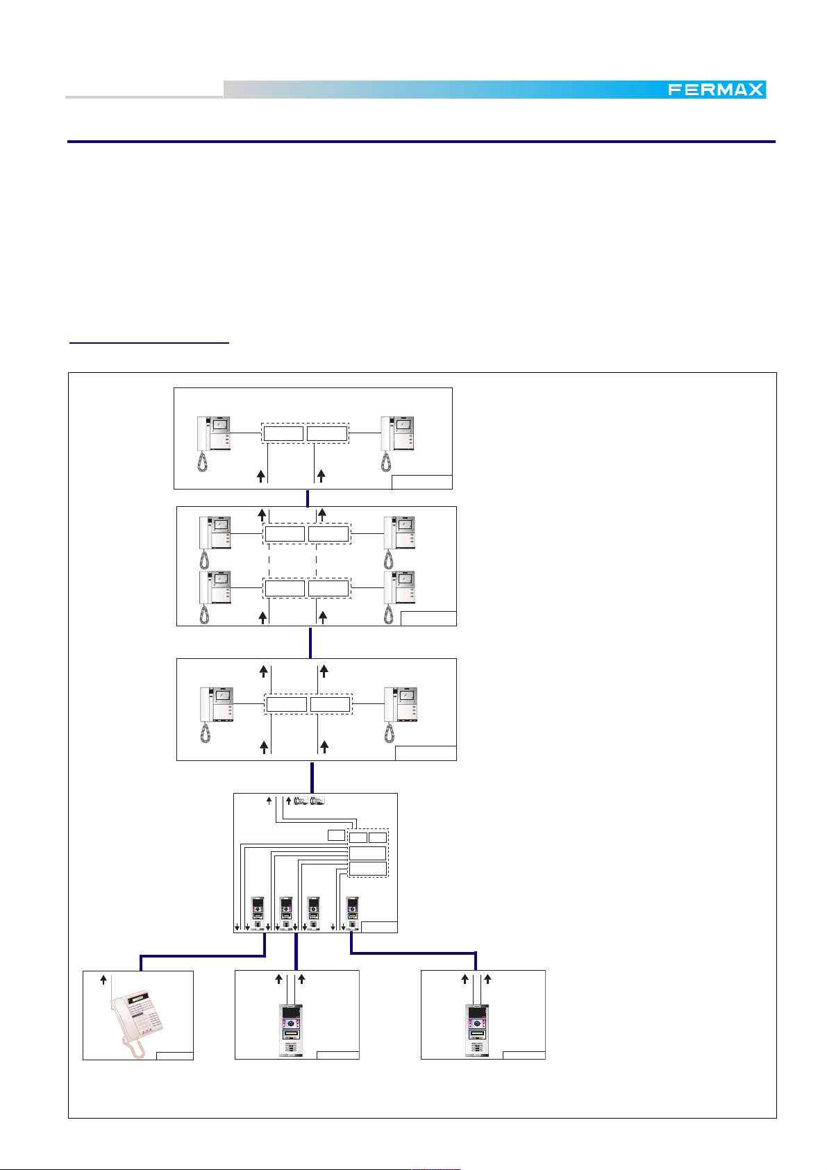
Technical Book
MDS
MDS
BLOCK DIAGRAMS and THUMBNAILS
This Technical Book presents the new FERMAX fashion for schematic diagrams: the THUMBNAIL system.
It makes the work of creating complex schematic diagrams based on the MDS Systems easier.
Every thumbnail is identified by a code (e.g.: MDS 95A). This code is the same as the one identifying the corresponding
detailed WIRING DIAGRAM shown in the ANNEX.
After making up your specific block schematic diagram with the necessary thumbnails, you can do the wiring one by
replacing each thumbnail with the corresponding wiring diagram from the ANNEX.
On the next page we offer some examples that should help you to understand how easy it is to manage the thumbnails
in order to elaborate any specific block diagram. Nevertheless, FERMAX is at your disposal to make any specific
diagrams you need. Please do not hesistate to contact us.
Example I: MDS DIGITAL
Video system, for one block with 2 accesses and 1 desktop guard unit. One branch.
HIGH RESOLUTION
FLAT MONITOR
1
2
REF.2424REF.2418
HIGH RESOLUTION
FLAT MONITOR
1
2
Monitors installed on the top floor
MDS 4C
HIGH RESOLUTION
FLAT MONITOR
1
REF.2418
2
REF.2424
HIGH RESOLUTION
FLAT MONITOR
1
2
Monitors installed on the middle floors
HIGH RESOLUTION
FLAT MONITOR
1
REF.2418
2
REF.2424
HIGH RESOLUTION
FLAT MONITOR
1
2
MDS 4B
HIGH RESOLUTION
FLAT MONITOR
HIGH RESOLUTION
1
2
REF.2424REF.2418
FLAT MONITOR
1
2
Monitors installed on the first floor
MDS 4A
26
+
-
D1D2
+
-
VM
BUS
BUS
REF. 2424
REF. 2418
V
V
-
-
TELEPHONES
VIDEO
PGM
1
4
312 4
BUS
BUS
D1D2
-+
34123 6 21 641 4236 63214
26
+
-+
+M-23-VM+
V-+M
V
VM-VM
REF.2421
REF.8830
REF.2070
REF.8840
DIGITAL MODULE
SWITCHERS MODULE
Central unit up to 10 panels.
MDS DIGITAL
1
4
Desk top guard unit
Panel 00 (*)
Pag. 30
HIGH RESOLUTION
CCD CAMERA
CCD CAMERA
PAN &TILT
PAN &TILT
LCD DIGITAL SYSTEM
123
456
789
A0B
3
2
6
5
9
8
7
#
B
0
*
A
MDS 12A
LCD DIGITAL SYSTEM
LCD DIGITAL SYSTEM
123
456
789
A0B
HIGH RESOLUTION
CCD CAMERA
PAN &TILT
LCD DIGITAL SYSTEM
123
456
789
A0B
First panel
Panel 01 (*)
CCD CAMERA
PAN &TILT
123
456
789
A0B
.......
MDS 10C
LCD DIGITAL SYSTEM
123
456
789
A0B
CCD CAMERA
PAN &TILT
MDS 16A
HIGH RESOLUTION
CCD CAMERA
PAN &TILT
LCD DIGITAL SYSTEM
123
456
789
A0B
Second panel
Panel 02 (*)
MDS 10C
(*) Configure the panel number
accordingly. See page 25.
HIGH RESOLUTION
HIGH RESOLUTION
HIGH RESOLUTION
Page 31

Technical Book
MDS 9C
123
456
789
A0B
LCD DIGITAL SYSTEM
MDS 9C
123
456
789
A0B
LCD DIGITAL SYSTEM
MDS 9C
123
456
789
A0B
LCD DIGITAL SYSTEM
REF.2424REF.2418
MDS 4A
1
2
HIGH RESOLUTION
FLAT MONITOR
1
2
HIGH RESOLUTION
FLAT MONITOR
REF.2424
REF.2424REF.2418
REF.2418
MDS 4B
1
2
HIGH RESOLUTION
FLAT MONITOR
1
2
HIGH RESOLUTION
FLAT MONITOR
1
2
HIGH RESOLUTION
FLAT MONITOR
1
2
HIGH RESOLUTION
FLAT MONITOR
REF.2424
REF.2424REF.2418
REF.2418
MDS 4B
1
2
HIGH RESOLUTION
FLAT MONITOR
1
2
HIGH RESOLUTION
FLAT MONITOR
1
2
HIGH RESOLUTION
FLAT MONITOR
1
2
HIGH RESOLUTION
FLAT MONITOR
REF.2424REF.2418
MDS 4C
1
2
HIGH RESOLUTION
FLAT MONITOR
1
2
HIGH RESOLUTION
FLAT MONITOR
MDS 67B
V
26
D1D2
+
-+
D1D2
26
BUS
PGM
-
BUS
-
341236 21641 4236 63214
TELEPHONES
REF. 2424
312 4
+
VM
+
BUS
V
-+
M
BUS
V
-
-
VIDEO
REF. 2418
-+
V
1
+
M
-
23
-
VM
+
4
VM
-
VM
.......
REF.8830
REF.2070
DIGITAL MODULE
SWITCHERS MODULE
REF.2421
REF.8840
123
456
789
A0B
LCD DIGITAL SYSTEM
123
456
789
A0B
LCD DIGITAL SYSTEM
123
456
789
A0B
LCD DIGITAL SYSTEM
MDS
MDS
Example II: MDS DIGITAL.
2 Video general entrances, 1 wall guard unit and 3 interior blocks with two audio accesses in each.
1
2
FLAT MONITOR
HIGH RESOLUTION
MDS 4C
REF.2424REF.2418
1
2
FLAT MONITOR
HIGH RESOLUTION
1
2
FLAT MONITOR
HIGH RESOLUTION
REF.2424REF.2418
MDS 4A
BLOCK 3
Central nº 03 (*)
BLOCK 2
Central nº 02 (*)
ACESS 2
Panel nº 02 (*)
MDS 9C
123
456
789
A0B
LCD DIGITAL SYSTEM
ACESS 1
Panel nº 01 (*)
ACESS 2
Panel nº 02 (**)
1
2
FLAT MONITOR
HIGH RESOLUTION
REF.2424REF.2418
1
2
FLAT MONITOR
HIGH RESOLUTION
1
2
FLAT MONITOR
HIGH RESOLUTION
ACESS 1
Panel nº 01 (**)
1
2
1
2
FLAT MONITOR
MDS 4C
HIGH RESOLUTION
REF.2424
REF.2418
1
2
FLAT MONITOR
HIGH RESOLUTION
FLAT MONITOR
HIGH RESOLUTION
REF.2424
REF.2418
1
2
FLAT MONITOR
HIGH RESOLUTION
MDS 4B
2
FLAT MONITOR
HIGH RESOLUTION
REF.2424REF.2418
1
2
FLAT MONITOR
HIGH RESOLUTION
MDS 4A
REF.2421
BLOCK 1
Central nº 01 (*)
REF.2070
SWITCHERS MODULE
DIGITAL MODULE
REF.8840
REF.8830
341236 21641 4236 63214
312 4
REF. 2424
TELEPHONES
V
+
-
-
PGM
26
D1D2
BUS
BUS
D1D2
26
-+
VM
+
VM
+
4
VM
+
M
23
VIDEO
V
-+
1
REF. 2418
V
+
-
M
-
V
BUS
BUS
VM
-+
123
456
789
A0B
LCD DIGITAL SYSTEM
.......
123
456
789
A0B
LCD DIGITAL SYSTEM
123
456
789
A0B
LCD DIGITAL SYSTEM
1
MDS 67B
MDS 9C
123
456
789
A0B
LCD DIGITAL SYSTEM
ACESS 2
Panel nº 02 (**)
MDS 9C
123
456
789
A0B
LCD DIGITAL SYSTEM
ACESS 1
Panel nº 01 (**)
MDS 10C
EXIT BUTTON
SEE MICROSWITCHES
PROGRAMMING TABLE
ABCD
CN2
Cp1
-
Ck
Dt
-+
CN3
....
....
ABCD
AbAb Tc
MDS
CITY LINE
CITY LINE
DISPLAY DIGITAL
TECLADO
DIGITAL MDS
COD.98227
26SB
Cp2
COD.98208
COD.98589
UNIVERSAL AMPLIFIER
AMPLIFICADOR UNIVERSAL
REF.8028
-
87654321
..........
..........
Sb
TELECAMARA
Sa
32 6
-+
CT VM
ON
-
1
CN5
Ab
L-L+632
1
Cp1
+
6+Tc+-32
1
Cp
CN8 SW1
F U
3 2 1
CN1
M.D.S. VIDEO PANEL REF.87701
REF.5918
SENSOR
OPEN DOOR
VARISTOR
REF.2958
ELECTRIC LOCK
REF.5919
G.ENTRANCE
12 Vdc - 500 mA.
Panel nº 03 (**)
MDS 10C
PAN &TILT
CCD CAMERA
HIGH RESOLUTION
123
456
789
A0B
LCD DIGITAL SYSTEM
G.ENTRANCE
Panel nº 02 (**)
REF.2421
341236 21641 4236 63214
312 4
REF. 2424
TELEPHONES
V
+
-
-
PGM
26
D1D2
BUS
BUS
Central nº 00 (*)
D1D2
26
-+
VM
+
VM
+
4
VM
+
M
23
VIDEO
V
-+
1
REF. 2418
V
+
-
M
-
V
BUS
BUS
VM
-+
GENERAL ENTRANCES
REF.2070
REF.8840
REF.8830
SWITCHERS MODULE
DIGITAL MODULE
LCD DIGITAL SYSTEM
LCD DIGITAL SYSTEM
LCD DIGITAL SYSTEM
MDS 67A
123
456
789
A0B
.......
123
456
789
A0B
123
456
789
A0B
MDS 10C
PAN &TILT
CCD CAMERA
HIGH RESOLUTION
123
456
789
A0B
LCD DIGITAL SYSTEM
TO THE CENTRAL
UNIT
MDS 11C
123
456
789
A0B
LCD DIGITAL SYSTEM
GUARD UNIT
Panel nº 01 (**)
block. Configure Central nº 00 as general entrance. See page 18.
(*) Configure FXL card according to the Central number. Configure short or long depending of the numeration of the apartments in each
(**) Configure the codification microswitches according to the panel number. See page 25
Pag. 31
Page 32

Technical Book
MDS 49U
ACCESS 1
ACCESS 2
REF.8830
REF.2443
REF.8840
REF.2070
123
456
789
A0
HIGH RESOLUTION
CCD CAMERA
PAN &TILT
MULTIPLEXED DIGITAL SYSTEM
123
456
789
A0
HIGH RESOLUTION
CCD CAMERA
PAN &TILT
MULTIPLEXED DIGITAL SYSTEM
MDS 95B
MDS CITY/DIRECT
1
2
4
3
5
6
7
8
9
*
0
#
A
B
STANDARD
TERMINAL
SCREW
MDS 23U
REF.2448
ACCESS 1
ACCESS 2
REF.2443
REF.8830
REF.2443
REF.8840
REF.2070
STANDARD
SCREW
TERMINAL
D2
D1
2
6
+
41
2
6 32316
4
43
3
12
AUD
IO DECODER 4
DEC
ODER DE AUDIO
4
6
2
434
V
-
-+
62
PGM
BUS
BUS
D2
D1
21
1
MA
DE IN SPAIN
R
EF. 2424
TELEPHONES
TELEFONOS /
DECODER N§:
6
VIDEO 3
4 SALIDAS
DISTRIBUIDO
R VIDEO
VIDEO 4
M
+-
VM
+
-
V
VIDEO 2VIDEO
3
VIDEO 2
+
V
34
-
-
BUS
+
MV
BUS
DISTRIBUIDOR VIDEO
VIDEO DISTRIBUTOR
VIDE
O 1
VIDEO 1
REF.2418
MADE IN SPAIN
PUENTE
CORTAR
+
MV
-
-
MV
M
VIDEO 4
-
V
+
HIGH PERFORMANCE
MULTIPLEXED DIGITAL SYSTEM
STOP
HIGH PERFORMANCE
MULTIPLEXED DIGITAL SYSTEM
STOP
REF.2425
REF.2419
MDS 5C
1
2
HIGH RESOLUTION
FLAT MONITOR
1
2
HIGH RESOLUTION
FLAT MONITOR
MDS 5B
REF.2425
REF.2425
REF.2419
REF.2419
1
2
HIGH RESOLUTION
FLAT MONITOR
1
2
HIGH RESOLUTION
FLAT MONITOR
1
2
HIGH RESOLUTION
FLAT MONITOR
1
2
HIGH RESOLUTION
FLAT MONITOR
REF.2425
REF.2419
MDS 5A
1
2
HIGH RESOLUTION
FLAT MONITOR
1
2
HIGH RESOLUTION
FLAT MONITOR
MDS 29U
REF.2448
ACCESS 1
REF.8830 REF.8840
REF.2070
STANDARD
SCREW
TERMINAL
D2
D1
2
6
+
4126 32316
4
43
3
12
AUDIO DE
CODER 4
DECODER
DE AUDIO 4
6
2
434
V
-
-+
62
PGM
BUS
BUS
D2
D1
2
1
1
MADE IN SPA
IN
REF. 2424
TELEPHONES
TELEFONOS /
DECODER N§:
6
VIDEO 3
4 SALID
AS
DIS
TRIBUIDOR VIDE
O
VIDEO 4
M
+-
VM
+-
V
VIDEO 2
VIDEO 3
VIDEO 2
+
V
34
-
-
BUS
+
MV
BUS
DISTRIBUIDOR VIDEO
VIDEO DISTRIBUTOR
VIDEO 1
VIDEO 1
REF.2
418
MA
DE IN SPAIN
PUENTE
CORTAR
+
MV
- -
MV
M
VIDEO 4
-
V
+
HIGH PERFORMANCE
MULTIPLEXED DIGITAL SYSTEM
STOP
MDS 3A
REF.2425
MDS 3B
REF.2425
REF.2425
REF.2425
MDS 3C
MDS
MDS
Example III: MDS DIRECT COMBINED WITH MDS CITY
One video general entrance, controlled by a MDS DIRECT panel, with MDS DIRECT guard unit and 2
internal blocks: Block A and block B, with the following features:
Block A.: Video. Two accesses. 8 apartments/ floor.
Block B: Audio only. One access. 8 apartments/floor
Block 02-Access 00 (*)
(*) See in page 26 how to configure each panel and acces number.
Block 01-Access 02 (*)
Block 01-Access 00 (*)
General guard unit
Pag. 32
Block 00-Acces 01 (*)
Block 00- Access 00 (*)
General entrances
Page 33

Technical Book
MDS
MDS
Example VI: MDS DIGITAL COMBINED WITH MDS CITY
This proyect is composed of:
One MDS Central unit, to control one general entrance and two guard units (one for the concierge and
another one for the guard).
Block A, with one access faced with MDS CITY panel. Monitors featured with panic button to call the guard.
Lift control.
Block B, same as block A, but using telephones instead of monitors. Outdoor panel is audio only.
REF.2430
MDS 34A
HIGH RESOLUTION
FLAT MONITOR
1
2
HIGH RESOLUTION
FLAT MONITOR
1
2
HIGH RESOLUTION
FLAT MONITOR
1
2
HIGH RESOLUTION
FLAT MONITOR
1
2
REF.2418
REF.2418
STANDARD
SCREW
TERMINAL
REF.2426REF.2418
REF.2426
REF.2426
REF.2426REF.2418
HIGH PERFORMANCE
MULTIPLEXED DIGITAL SYSTEM
STOP
Block A
Block 01-panel 00
REF.8830
ACCESS 1
26
-+
D2
D1
V
-
BUS
DECODER DE AUDIO 4
MADE IN SPAIN
AUDIO DECODER 4
REF. 2424
DECODER N§:
TELEFONOS /
TELEPHONES
PGM
1 4
BUS
D1
D2
-+
2
1
41263231 4 66433126234
62
REF.8840
REF.2070
MDS 26U
HIGH RESOLUTION
FLAT MONITOR
1
2
MDS 6C
HIGH RESOLUTION
FLAT MONITOR
1
2
HIGH RESOLUTION
FLAT MONITOR
1
2
MDS 6B
HIGH RESOLUTION
FLAT MONITOR
1
2
MDS 6A
+
-
MV
BUS
DISTRIBUIDOR VIDEO
MADE IN SPAIN
V
-
4 SALIDAS
REF.2418
CORTAR
PUENTE
DISTRIBUIDOR VIDEO
34
VIDEO DISTRIBUTOR
VIDEO 3
VIDEO 2
VIDEO 1
VIDEO 4
BUS
VIDEO 2
VIDEO 1
VIDEO 3
VIDEO 4
-
-
+
+-
+
+
V
M
V
M
M-V
M+V-MV
Relay decoders
for lift control
REF.2430
MDS 34A
REF.2426
REF.2426
REF.2426
REF.2426
26
-+
D2
D1
V
-
BUS
DECODER DE AUDIO 4
MADE IN SPAIN
AUDIO DECODER 4
REF. 2424
DECODER N§:
TELEFONOS /
TELEPHONES
PGM
1 4
BUS
D1
D2
-+
2
1
41263231 4 66433126234
62
REF.8840
HIGH PERFORMANCE
MULTIPLEXED DIGITAL SYSTEM
STOP
ACCESS 1
STANDARD
SCREW
TERMINAL
MDS 30U
Block B
Block 00-panel 00
MDS 1C
MDS 1B
MDS 1A
REF.2070
26
+
-
D1D2
+
-
VM
BUS
BUS
REF. 2424
REF. 2418
V
V
-
-
TELEPHONES
VIDEO
PGM
1
4
312 4
BUS
BUS
D1D2
-+
34123621 641 4236 63214
26
+
-+
+M-23-VM+
V-+M
V
VM-VM
REF.8840
REF.2421
REF.2070
REF.8830
DIGITAL MODULE
SWITCHERS MODULE
MDS DIGITAL
3
2
1
6
5
4
9
8
7
#
B
0
*
A
MDS 12A
Concierge
Panel 00
HIGH RESOLUTION
CCD CAMERA
PAN &TILT
LCD DIGITAL SYSTEM
123
456
789
A0B
MDS DIGITAL
3
2
1
6
5
4
9
8
7
#
B
0
*
A
MDS 12A
Guard
Panel 01
HIGH RESOLUTION
HIGH RESOLUTION
CCD CAMERA
CCD CAMERA
PAN &TILT
PAN &TILT
LCD DIGITAL SYSTEM
LCD DIGITAL SYSTEM
123
123
456
456
789
789
A0B
A0B
.......
General entrance
Panel 02
HIGH RESOLUTION
CCD CAMERA
PAN &TILT
LCD DIGITAL SYSTEM
123
456
789
A0B
MDS 16A
HIGH RESOLUTION
CCD CAMERA
PAN &TILT
LCD DIGITAL SYSTEM
123
456
789
A0B
MDS 10C
Pag. 33
Page 34

Technical Book
REF.2424REF.2418
MDS 4C
1
2
HIGH RESOLUTION
FLAT MONITOR
1
2
HIGH RESOLUTION
FLAT MONITOR
MDS
MDS
THUMBNAILS FOR DECODER BUS
Apply these thumbnails for the part corresponding to the floor distribution.
Decoders 4
REF.2424
REF.2424
REF.2424
MDS 2A
MDS 2B
Floor distribution for Audio systems with Decoder 4 ref. 2424. Beginning, middle and last on the riser.
REF.2424
MDS 2C
HIGH RESOLUTION
FLAT MONITOR
1
2
HIGH RESOLUTION
FLAT MONITOR
1
2
REF.2424REF.2418
HIGH RESOLUTION
FLAT MONITOR
1
2
HIGH RESOLUTION
FLAT MONITOR
1
2
REF.2418
REF.2418
REF.2424
REF.2424
MDS 4A
HIGH RESOLUTION
FLAT MONITOR
1
2
HIGH RESOLUTION
FLAT MONITOR
1
2
MDS 4B
Floor distribution for Video systems with Decoder and Video Distributor 4. First, middle and last on the riser.
Decoders 8
REF.2425
REF.2425
REF.2425
MDS 3A
MDS 3B
Floor distribution for Audio systems with Decoder 8 ref. 2425. First, middle and last on the riser.
HIGH RESOLUTION
FLAT MONITOR
1
2
HIGH RESOLUTION
FLAT MONITOR
1
2
REF.2425REF.2419
HIGH RESOLUTION
FLAT MONITOR
1
2
HIGH RESOLUTION
FLAT MONITOR
1
2
REF.2419
REF.2419
REF.2425
REF.2425
MDS 5A
HIGH RESOLUTION
FLAT MONITOR
1
2
HIGH RESOLUTION
FLAT MONITOR
1
2
MDS 5B
HIGH RESOLUTION
FLAT MONITOR
1
2
Floor distribution for Audio systems with Decoder 8 and Video Distributor 8. First, middle and last on the riser.
REF.2425
MDS 3C
REF.2425REF.2419
HIGH RESOLUTION
FLAT MONITOR
1
2
MDS 5C
Isodecoders
REF.2426
REF.2426
REF.2426
MDS 1A
MDS 1B
Floor distribution for Audio systems with Isodecoder ref 2425. First, middle and last on the riser.
HIGH RESOLUTION
FLAT MONITOR
1
2
HIGH RESOLUTION
FLAT MONITOR
1
2
REF.2426REF.2418
HIGH RESOLUTION
FLAT MONITOR
1
2
HIGH RESOLUTION
FLAT MONITOR
1
2
REF.2418
REF.2418
REF.2426
REF.2426
MDS 6A
HIGH RESOLUTION
FLAT MONITOR
1
2
HIGH RESOLUTION
FLAT MONITOR
1
2
MDS 6B
HIGH RESOLUTION
FLAT MONITOR
1
2
Floor distribution for Audio systems with Isodecoder and Video Distributor 4. First, middle and last on the riser.
Pag. 34
REF.2426
MDS 1C
HIGH RESOLUTION
FLAT MONITOR
REF.2426REF.2418
1
2
MDS 6C
Page 35

Technical Book
DIGITAL MODULE
MDS CENTRAL UNIT
MDS REPEATER
REF.2339
POWER SUPPLY
TO REGENERATE THE BUS SIGNAL
MDS
MDS
THUMBNAILS FOR DECODER BUS
Special Decoders
Thumbnails below represent decoders used in some special applications, such as sensor decoders, relay
decoders and/or panel decoders.
REF.2436
MDS 96A
Installations in which PANEL
decoders are being used.
SENSOR SENSOR
REF.2429
MDS 95A
Installations in which SENSOR
decoders are being used.
Installations in which RELAY
decoders are being used.
REF.2430
MDS 34A
Other applications in bus installations
Thumbnails below represent some applications to apply in the bus decoder, such us adding some power
supply in the middle of the riser to compensate the dropping voltage along the bus, splitting the bus into
several risers (with and without additional power supply) and connecting a standard City Kit to the output
decoder to be installed at the front door of single houses or villas.
FXL repeater (MDS 21A)
The FXL repeater device acts as a "data booster" that recovers the data signal assuring the data transmission in long installations (more than 1.200 mts). It can also be used for splitting the riser into 2 branches.
RISER 2 RISER 1
MDS REPEATER
REF.2339
MDS 21A
MDS CENTRAL UNIT
POWER SUPPLY
DIGITAL MODULE
DERIVATION 2 DERIVATION 1
MDS REPEATER
REF.2339
TO THE REST OF THE
INSTALLATION
MDS CENTRAL UNIT
POWER SUPPLY
DIGITAL MODULE
BRANCHES OF THE DECODERS BUS
FXL repeater working splitting into
2 risers (with signal regeneration).
Additional power supply
Extra power supply for audio installations.
Power supply installed beside a 2424/
2425 Audio decoder.
REF.2425
REF.8840
REF.2070
MDS 7B
DERIVATIONS OF THE DECODERS BUS
Split into 2 risers, in which the bus
continues to the rest of the installation
(i.e. to the next block).
REF.2426
REF.8840
REF.2070
MDS 7A
Extra power supply for audio installations.
Power supply installed beside a 2426
Isodecoder
FXL repeater acting as signal
regenerator only.
REF.8830
STANDARD
SCREW
REF.8840 REF.2070
TERMINAL
MDS 83A
Extra video & power supply in the
middle of the bus. Used only for
compensate dropping voltage in
very long installation.
Pag. 35
Page 36

Technical Book
REF.2419
MDS 75A
REF.2425
REF.8830
STANDARD
TERMINAL
SCREW
REF.8840 REF.2070
1
2
HIGH RESOLUTION
FLAT MONITOR
1
2
HIGH RESOLUTION
FLAT MONITOR
REF.2449
STANDARD
TERMINAL
SCREW
MDS 80A
REF.8830
MDS 22A
REF.8830REF.8830
REF.2448
-+
MV
3
V
BUS
VM
+-
CORTAR
PUENTE
4
-
BUS
6
REF. 2424
MADE IN SPAIN
TELEPHONES
DECODER N§:
TELEFONOS /
-+
D1
-
62
D2
2
PGM
6
D2
BUS
13124
VIDEO 4
V+-M+-M
D1
VIDEO 1
V
VIDEO 1
MADE IN SPAIN
REF.2418
VIDEO DISTRIBUTOR
DISTRIBUIDOR VIDEO
-+
V
-
+
VIDEO 2VVIDEO 3
+M-
4 SALIDAS
VIDEO 2
M
VIDEO 4
DISTRIBUIDOR VIDEO
VIDEO 3
V
BUS
24361 32146612334
2 4
AUDIO DECODER 4
DECODER DE AUDIO 4DECODER DE AUDIO 4
AUDIO DECODER 4
1
TELEFONOS /
DECODER N§:
TELEPHONES
DISTRIBUIDOR VIDEO
VIDEO DISTRIBUTOR
REF.2418
MADE IN SPAIN
VIDEO 1
VIDEO 1
+
BUS
-
4
PUENTE
CORTAR
-+
MV
BUS
V
3
VM
+-
2
BUS
V
VIDEO 3
DISTRIBUIDOR VIDEO
VIDEO 4
M
VIDEO 2
4 SALIDAS
-
M
+
VIDEO 3VVIDEO 2
+-V-
VD1M-+M-+V
VIDEO 4
42131
BUS
D2
6
PGM
2
D2
26
-
D1
+-
MADE IN SPAIN
REF. 2424
644332 6 641231 6342
VIDEO 3
PUENTE
CORTAR
DISTRIBUIDOR VIDEO
VIDEO DISTRIBUTOR
REF.2418
MADE IN SPAIN
VIDEO 1
VIDEO 1
+
BUS
-
4
-+
MV
BUS
V
3
VM
+-
DISTRIBUIDOR VIDEO
VIDEO 4
M
VIDEO 2
4 SALIDAS
M
+
VIDEO 3VVIDEO 2
+--
VV
4
BUS
BUS
D1
-+
D2
26
DECODER DE AUDIO 4
AUDIO DECODER 4
1
TELEFONOS /
DECODER N§:
TELEPHONES
2
V
42131
D2
6
PGM
2
-
D1
+-
MADE IN SPAIN
REF. 2424
644332 6 121 6342 3
MM-+V
VIDEO 4
6
MDS
MDS
THUMBNAILS FOR DECODER BUS
HIGH RESOLUTION
FLAT MONITOR
1
2
REF.2419
REF.2425
HIGH RESOLUTION
FLAT MONITOR
1
2
REF.8830
MDS 8A
Extra Video power supply in Video installations.
Beside a 2424/2425 Audio decoder.
Extra Video & Audio power supply in Video
installations. Beside a 2426 Isodecoder
Splitting the bus
REF.2448
STANDARD
SCREW
TERMINAL
MDS 84A
2 branches bifurcation.
To split the bus (Video installations only. To split the bus in only Audio installation just twist each wire with the other).
26
+-
D2
D1
V
-
BUS
DECODER DE AUDIO 4
MADE IN SPAIN
AUDIO DECODER 4
REF. 2424
DECODER N§:
TELEFONOS /
TELEPHONES
PGM
2
BUS
D1
D2
-+
1
42131
644332 6 121 6342 36
6
2
26
+-
D2
D1
V
-
BUS
MADE IN SPAIN
AUDIO DECODER 4
REF. 2424
DECODER N§:
TELEFONOS /
TELEPHONES
PGM
2
BUS
D2
D1
-+
1
42131
644332 6 641231 63424
6
2
62
-+
D1
D2
V
-
BUS
DECODER DE AUDIO 4DECODER DE AUDIO 4
MADE IN SPAIN
AUDIO DECODER 4
REF. 2424
DECODER N§:
TELEFONOS /
TELEPHONES
PGM
2 4
BUS
D2
D1
+-
6
13124
24361 32146612334
2
6
4 branches bifurcation.
REF.8840 REF.8840REF.8840
REF.2070 REF.2070REF.2070
SCREW CONNECTOR
MDS 99A
3 branches bifurcation with one power
supply in ech branch. Audio+ Video.
3 branches bifurcation with one power
supply in ech branch. Audio only.
To split the bus in 3 branches, but adding an additional power supply for each new branch. Video and Audio bus
repectivelly,
City Line KITS for villas
HIGH RESOLUTION
FLAT MONITOR
1
2
VIDEO SWITCHER
REF.8812
POWER SUPPLY
REF.8815
REF.2424REF.2418
General Entrance: VIDEO
Villas: VIDEO
VIDEO SWITCHER
REF.8811
POWER SUPPLY
REF.8980
REF.2424
General Entrance: AUDIO
Villas: AUDIO
VIDEO SWITCHER
REF.8811
POWER SUPPLY
REF.8980
MDS 90A
HIGH RESOLUTION
FLAT MONITOR
1
2
VIDEO SWITCHER
REF.8812
POWER SUPPLY
REF.8980
REF.2424REF.2418
General Entrance: VIDEO
Villas: AUDIO
HIGH RESOLUTION
FLAT MONITOR
1
2
VIDEO SWITCHER
REF.8812
POWER SUPPLY
REF.8980
MDS 76U
Residential area with audio MDS General Entrance and internal villas with 1L/ audio outdoor panel on the front door. This
diagrams is for villas.
Pag. 36
HIGH RESOLUTION
FLAT MONITOR
1
2
VIDEO SWITCHER
REF.8812
POWER SUPPLY
REF.8815
MDS 77U
Page 37

Technical Book
MDS
MDS
THUMBNAILS FOR SINGLE BLOCKS
Below are represented thumbnails to make diagrams for single blocks in either system: MDS DIGITAL,
MDS DIRECT or MDS CITY.
Single blocks with MDS DIGITAL
To make diagrams for installations with MDS DIGITAL system in a single building. (one central unit only).
MDS DIGITAL Central Units in standard configuration
These thumbnails are used ONLY to make diagrams for single blocks using the MDS DIGITAL system in
standard configurations
Combine them with the required MDS DIGITAL PANEL thumbnails and the required DECODER thumbnails.
26
+
-
D1D2
+
-
VM
BUS
BUS
REF. 2424
REF. 2418
V
V
-
26
+
-
D1D2
BUS
REF. 2424
V
-
TELEPHONES
PGM
312 4
26
+
-
D1D2
+
-
VM
BUS
BUS
REF. 2424
REF. 2418
V
V
-
-
TELEPHONES
VIDEO
PGM
1
4
312 4
BUS
BUS
D1D2
-+
34123 6 21 641 4236 63214
26
+
-+
+M-23-VM+
V-+M
V
26
+
-
D1D2
BUS
REF. 2424
V
-
TELEPHONES
PGM
312 4
BUS
D1D2
-+
34123 6 21 641 4236 63214
26
REF.2420
REF.8840
REF.2070
VM-VM
REF.8840
REF.2420
REF.2070
REF.8830
DIGITAL MODULE
DIGITAL MODULE
BUS
D1D2
-+
34123 6 21 641 4236 63214
26
REF.2421
REF.8840
REF.2070
DIGITAL MODULE
SWITCHERS MODULE
-
TELEPHONES
VIDEO
PGM
1
4
312 4
BUS
BUS
D1D2
-+
34123 6 21 641 4236 63214
26
+
-+
+M-23-VM+
V-+M
V
VM-VM
REF.8840
REF.2421
REF.2070
REF.8830
DIGITAL MODULE
SWITCHERS MODULE
LCD DIGITAL SYSTEM
LCD DIGITAL SYSTEM
123
123
456
456
789
789
A0B
A0B
MDS 13A
Central Unit 1 or 2 panels.
Audio installations.
HIGH RESOLUTION
HIGH RESOLUTION
CCD CAMERA
CCD CAMERA
PAN &TILT
PAN &TILT
LCD DIGITAL SYSTEM
LCD DIGITAL SYSTEM
123
123
456
456
789
789
A0B
A0B
MDS 15A
Central Unit 1 or 2 panels.
Video installations.
LCD DIGITAL SYSTEM
LCD DIGITAL SYSTEM
LCD DIGITAL SYSTEM
123
123
456
456
789
789
A0B
A0B
LCD DIGITAL SYSTEM
123
123
456
456
789
789
A0B
A0B
........
MDS 14A
Central Unit up to 10 panels.
Audio installations.
HIGH RESOLUTION
CCD CAMERA
CCD CAMERA
PAN &TILT
PAN &TILT
LCD DIGITAL SYSTEM
LCD DIGITAL SYSTEM
123
123
456
456
789
789
A0B
A0B
Central Unit up to 10 panels.
Video installations.
CCD CAMERA
CCD CAMERA
PAN &TILT
PAN &TILT
LCD DIGITAL SYSTEM
LCD DIGITAL SYSTEM
123
123
456
456
789
789
A0B
A0B
.......
MDS 16A
HIGH RESOLUTION
HIGH RESOLUTION
HIGH RESOLUTION
MDS DIGITAL Central Units in multistairs configuration or splitting the bus into several risers
These thumbnails are used ONLY to make diagrams for single blocks using the MDS DIGITAL system in
multistairs configurations, i.e., in which the same central unit can control several independent stairs.
These are also used to make diagrams in which splitting the bus in several branches from the central unit
is required.
Combine them with the required MDS DIGITAL PANEL thumbnails and the required DECODER thumbnails.
REF.2421
REF.8830
REF.2070
REF.2420
REF.2070
STANDARD
SCREW
TERMINAL
LCD DIGITAL SYSTEM
123
456
789
A0B
REF.8840
DIGITAL MODULE
LCD DIGITAL SYSTEM
123
456
789
A0B
MDS 64A
Split into several risers in video
installations up to 10 panels.
Multistairs video up to 10 blocks (V3.1)
REF.2448
REF.2449
REF.2449
STANDARD
SCREW
TERMINAL
HIGH RESOLUTION
CCD CAMERA
PAN &TILT
LCD DIGITAL SYSTEM
123
456
789
A0B
REF.2420
REF.8830
REF.2070
REF.8840
DIGITAL MODULE
HIGH RESOLUTION
CCD CAMERA
PAN &TILT
LCD DIGITAL SYSTEM
123
456
789
A0B
MDS 65A
Split into several risers in video
installations up to 10 panels.
Multistairs video up to 10 blocks (V3.1)
REF.2449
STANDARD
SCREW
TERMINAL
HIGH RESOLUTION
HIGH RESOLUTION
CCD CAMERA
CCD CAMERA
PAN &TILT
PAN &TILT
LCD DIGITAL SYSTEM
LCD DIGITAL SYSTEM
123
123
456
456
789
789
A0B
A0B
Split into several risers in video
installations up to 2 panels.
Multistairs video up to 2 blocks (V3.1)
REF.8840
DIGITAL MODULE
SWITCHERS MODULE
HIGH RESOLUTION
HIGH RESOLUTION
CCD CAMERA
CCD CAMERA
PAN &TILT
PAN &TILT
LCD DIGITAL SYSTEM
LCD DIGITAL SYSTEM
123
123
456
456
789
789
A0B
A0B
.......
MDS 74A
MDS DIGITAL panels
To combine with the thumbnails above.
MDS DIGITAL
3
2
1
6
5
4
9
LCD DIGITAL SYSTEM
123
456
789
A0B
MDS 9C
LCD DIGITAL SYSTEM
123
456
789
A0B
PAN &TILT
MDS 10C
LCD DIGITAL SYSTEM
123
456
789
A0B
MDS 11C
HIGH RESOLUTION
CCD CAMERA
Audio MDS-Digital panel Video MDS-Digital panel Wall mounting guard unit Desk top guard unit
8
7
#
0
*
A
B
MDS 12A
Pag. 37
Page 38

Technical Book
MDS 95B
MDS CITY/DIRECT
1
2
4
3
5
6
7
8
9
*
0
#
A
B
STANDARD
TERMINAL
SCREW
MDS
MDS
THUMBNAILS FOR SINGLE BLOCKS
Single blocks with MDS CITY
To make diagrams for installations with MDS CITY panels in a single block.
Combine them with the required DECODER thumbnails.
2-6
-+
D2
D1
V
-
BUS
DECODER DE AUDIO 4
MADE IN SPAIN
AUDIO DECODER 4
REF. 2424
DECODER N§:
TELEFONOS /
TELEPHONES
PGM
1
BUS
D1
D2
+
4126 32316443312
6243 4
21
6
62
REF.8840 REF.2070
HIGH PERFORMANCE
MULTIPLEXED DIGITAL SYSTEM
STOP
ACCESS 1
HIGH PERFORMANCE
MULTIPLEXED DIGITAL SYSTEM
STOP
ACCESS 1
MDS 117U
+
2-6
-+
D2
D1
BUS
PGM
BUS
D1
D2
62
V
-
DECODER DE AUDIO 4
MADE IN SPAIN
AUDIO DECODER 4
REF. 2424
DECODER N§:
TELEFONOS /
TELEPHONES
1
62434
21
4126 32316443312
6
HIGH PERFORMANCE
MULTIPLEXED DIGITAL SYSTEM
STOP
REF.8840 REF.2070
ACCESS 2
MDS 103U
3
2
1
6
5
4
9
8
7
#
B
0
*
A
MDS CITY/DIRECT
STANDARD
SCREW
TERMINAL
MDS 97A
MDS CITY audio panel
Blocks with 1 entrance
+
-
26
-+
D2
D1
MV
V
-
BUS
BUS
DISTRIBUIDOR VIDEO
DECODER DE AUDIO 4
MADE IN SPAIN
MADE IN SPAIN
V
-
4 SALIDAS
AUDIO DECODER 4
REF.2418
REF. 2424
CORTAR
DECODER N§:
PUENTE
DISTRIBUIDOR VIDEO
34
TELEFONOS /
TELEPHONES
VIDEO DISTRIBUTOR
PGM
VIDEO 3
VIDEO 2
VIDEO 1
VIDEO 4
1 4
BUS
VIDEO 2
VIDEO 1
VIDEO 3
VIDEO 4
BUS
+
-
-
+
+-
+
M
V
M
M-V
M+V-MV
V
D1
D2
-+
2
1
412632314 66433126234
62
REF.8840
REF.8830
REF.2070
HIGH PERFORMANCE
MULTIPLEXED DIGITAL SYSTEM
STOP
ACCESS 1
MDS CITY video panel
Blocks with 1 entrance
MDS 118U
MDS CITY audio panels
Blocks with 2 entrances
+
-
26
-+
D2
D1
MV
V
-
BUS
BUS
DECODER DE AUDIO 4
MADE IN SPAIN
V
-
AUDIO DECODER 4
REF. 2424
CORTAR
DECODER N§:
PUENTE
34
TELEFONOS /
TELEPHONES
PGM
1 4
BUS
BUS
+V
M
D1
D2
-+
2
1
412632314 66433126234
62
REF.8840
REF.8830
REF.2070
REF.2443
HIGH PERFORMANCE
MULTIPLEXED DIGITAL SYSTEM
STOP
ACCESS 1
HIGH PERFORMANCE
MULTIPLEXED DIGITAL SYSTEM
STOP
ACCESS 2
MDS 87U
MDS CITY video panels
Blocks with 2 entrances
DISTRIBUIDOR VIDEO
MADE IN SPAIN
4 SALIDAS
REF.2418
DISTRIBUIDOR VIDEO
VIDEO DISTRIBUTOR
VIDEO 3
VIDEO 2
VIDEO 1
VIDEO 4
VIDEO 2
VIDEO 1
VIDEO 3
VIDEO 4
-
-
+
+
+
M
V
M-V
M+V-MV
Single blocks with MDS DIRECT
To make diagrams for installations with MDS DIRECT panels in a single block.
Combine them with the required DECODER thumbnails.
2-6
-+
D2
26
-+
D2D1
V
-
BUS
DECODER DE AUDIO 4
MADE IN SPAIN
AUDIO DECODER 4
REF. 2424
DECODER N§:
TELEFONOS /
TELEPHONES
PGM
3
1
2
BUS
D1
D2
-+
464123
3
12436
1
2
231464 6
62
REF.8840 REF.2070
D1
V
-
BUS
DECODER DE AUDIO 4
MADE IN SPAIN
AUDIO DECODER 4
REF. 2424
DECODER N§:
TELEFONOS /
TELEPHONES
PGM
1
BUS
D1
D2
+
4126 32316443312
62434
21
6
62
REF.8840 REF.2070
MDS DIRECT/CITY guard
unit in audio installations
3
2
1
6
5
4
9
8
7
#
B
0
*
A
MDS CITY/DIRECT
STANDARD
SCREW
TERMINAL
MDS 95B
MDS DIRECT/CITY guard
unit in video installations
3
2
1
6
5
4
9
8
7
#
B
0
*
A
MDS CITY/DIRECT
MULTIPLEXED DIGITAL SYSTEM
123
456
789
A0
ACCESS 1
MDS DIRECT audio panel
Blocks with 1 entrance
26
-+
D2D1
+
V
M
V
-
BUS
BUS
DECODER DE AUDIO 4
DISTRIBUIDOR VIDEO
MADE IN SPAIN
MADE IN SPAIN
V
-
AUDIO DECODER 4
4 SALIDAS
REF. 2424
REF.2418
CORTAR
DECODER N§:
PUENTE
TELEFONOS /
DISTRIBUIDOR VIDEO
34
TELEPHONES
VIDEO DISTRIBUTOR
PGM
3
1
2
VIDEO 1
VIDEO 4
VIDEO 3
VIDEO 2
BUS
BUS
VIDEO 4
VIDEO 1
VIDEO 2
VIDEO 3
D1
D2
-+
3
12436
1
2
62314464 46123
62
-
-
+
+
+
+
V
M-V
M-V
V
M-M+V
M
REF.8830 REF.8840
REF.2070
HIGH RESOLUTION
CCD CAMERA
PAN &TILT
MULTIPLEXED DIGITAL SYSTEM
123
456
789
A0
ACCESS 1
MDS DIRECT video panel
Blocks with 1 entrance
Pag. 38
MDS 71U
MDS 70U
MULTIPLEXED DIGITAL SYSTEM
123
456
789
A0
ACCESS 2
MULTIPLEXED DIGITAL SYSTEM
123
456
789
A0
ACCESS 1
MDS 116U
MDS DIRECT audio panels
Blocks with 2 entrances
26
-+
D2D1
+
V
M
V
-
BUS
BUS
DECODER DE AUDIO 4
DISTRIBUIDOR VIDEO
MADE IN SPAIN
MADE IN SPAIN
V
-
AUDIO DECODER 4
4 SALIDAS
REF. 2424
REF.2418
CORTAR
DECODER N§:
PUENTE
TELEFONOS /
DISTRIBUIDOR VIDEO
34
TELEPHONES
VIDEO DISTRIBUTOR
PGM
3
1
2
VIDEO 1
VIDEO 4
VIDEO 3
VIDEO 2
BUS
BUS
VIDEO 4
VIDEO 1
VIDEO 2
VIDEO 3
D1
D2
-+
3
12436
1
2
62314464 46123
62
-
-
+
+
+
+
V
M-V
M-V
V
M-M+V
M
REF.8830
REF.8840
REF.2443
REF.2070
HIGH RESOLUTION
CCD CAMERA
PAN &TILT
MULTIPLEXED DIGITAL SYSTEM
123
456
789
A0
ACCESS 2
HIGH RESOLUTION
CCD CAMERA
PAN &TILT
MULTIPLEXED DIGITAL SYSTEM
123
456
789
A0
ACCESS 1
MDS 98U
MDS DIRECT video panels
Blocks with 2 entrances
STANDARD
SCREW
TERMINAL
MDS 97A
MDS DIRECT/CITY guard
unit in audio installations
MDS DIRECT/CITY guard
unit in video installations
Page 39

Technical Book
MDS
MDS
THUMBNAILS FOR RESIDENTIAL AREAS. GENERAL ENTRANCES.
The Thumbnails below are for residential areas and combinations with any MDS system: MDS DIGITAL,
MDS CITY or MDS DIRECT. These Thumbnails represent the General Entrances.
General Entrances with MDS DIGITAL
To make installation diagrams for general entrances.
MDS DIGITAL combined with MDS DIGITAL
To make installation diagrams for general entrances in residential areas where the interior blocks are also
MDS DIGITAL.
The followingThumbnails represent the Central Unit asigned as General Entrance of an MDS DIGITAL
system with an installation in series, i. e. the central unit is connected via FXL to another central unit of an
inner block. The Decoder BUS can be utilised for relay/sensor decoders, or AUDIO decoders for common
areas (if there are any).
They will be combined with the necessary INTERIOR BLOCKS and PANELS Thumbnails.
26
+
-
D1D2
BUS
-+
26
+
-
D1D2
BUS
V
-
PGM
BUS
D1D2
26
LCD DIGITAL SYSTEM
123
456
789
A0B
REF. 2424
TELEPHONES
312 4
341236 21 641 4236 6321 4
REF.8830
REF.8840
DIGITAL MODULE
26
+
-
D1D2
+
-
VM
BUS
BUS
REF. 2424
REF. 2418
V
V
-
-
TELEPHONES
VIDEO
PGM
1
4
312 4
BUS
BUS
D1D2
-+
34123 6 21 641 4236 6321 4
26
+
-+
+M-23-VM+
V-+M
V
VM-VM
REF.2070
REF.8840
DIGITAL MODULE
HIGH RESOLUTION
CCD CAMERA
PAN &TILT
LCD DIGITAL SYSTEM
123
456
789
A0B
REF.2420
REF.2070
REF.2420
CentralUnit assigned as
general entry with 1 audio
panel.
Configuration SERIE.
MDS 17A
CentralUnit assigned as
general entry with 1 video
panel.
Configuration SERIE.
MDS 58A
REF. 2424
V
-
TELEPHONES
PGM
3124
BUS
D1D2
-+
341236 21 641 4236 63214
26
REF.2421
REF.2070REF.8840
DIGITAL MODULE
SWITCHERS MODULE
LCD DIGITAL SYSTEM
LCD DIGITAL SYSTEM
LCD DIGITAL SYSTEM
123
456
789
A0B
+
-
VM
BUS
REF. 2418
V
-
VIDEO
1
4
BUS
-+
+
-+
+M-23-VM+
V-+M
V
VM-VM
123
123
456
456
789
789
A0B
A0B
........
26
+
-
D1D2
BUS
REF. 2424
V
-
TELEPHONES
PGM
312 4
BUS
D1D2
34123621 641 4236 63214
26
REF.8830
REF.8840
MDS 19A
REF.2421
REF.2070
DIGITAL MODULE
SWITCHERS MODULE
HIGH RESOLUTION
HIGH RESOLUTION
HIGH RESOLUTION
CCD CAMERA
PAN &TILT
LCD DIGITAL SYSTEM
123
456
789
A0B
CCD CAMERA
CCD CAMERA
PAN &TILT
PAN &TILT
LCD DIGITAL SYSTEM
LCD DIGITAL SYSTEM
123
123
456
456
789
789
A0B
A0B
.......
MDS 59A
CentralUnit assigned as
general entry with up to 9
audio panels.
Configuration SERIE.
CentralUnit assigned as
general entry with 1 video
panels.
Configuration SERIE.
In cases in which it is necessary to form a residential area with a "star configuration", i.e. the central unit we
assign as general entrance and its panels are situated in the centre of the area with the blocks around it,
we can split the FXL network into as many branches as required (using a connector strip, for example, in
audio installations).
In video installations, as well as the audio connector strip, we shall need video distributors to split the video
signal, as shown in the following Thumbnails:
REF.2448
STANDARD
SCREW
TERMINAL
To divide the video signal
into 2 branches. STAR
configuration.
MDS 84A
MDS DIGITAL Panels
To be combined with the Thumbnails above.
HIGH RESOLUTION
CCD CAMERA
LCD DIGITAL SYSTEM
123
456
789
A0B
MDS 9C
MDS Digital Audio Panel
MDS DigitalVideo Panel
LCD DIGITAL SYSTEM
123
456
789
A0B
PAN &TILT
MDS 10C
REF.2449
STANDARD
SCREW
TERMINAL
MDS 80A
LCD DIGITAL SYSTEM
123
456
789
A0B
MDS 11C
MDS Digital Wall
Mounted Guard Unit
To divide the video signal
into 4 branches. STAR
configuration.
MDS DIGITAL
3
2
1
6
5
4
9
8
7
#
B
0
*
A
MDS 12A
MDS Digital Desktop
Guard Unit
Pag. 39
Page 40

Technical Book
MDS 55A
REF.8840
DIGITAL MODULE
REF.2421
REF.2070
SWITCHERS MODULE
........
123
456
789
A0B
LCD DIGITAL SYSTEM
123
456
789
A0B
LCD DIGITAL SYSTEM
123
456
789
A0B
LCD DIGITAL SYSTEM
123
456
789
A0B
LCD DIGITAL SYSTEM
HIGH PERFORMANCE
MULTIPLEXED DIGITAL SYSTEM
STOP
123
456
789
A0B
LCD DIGITAL SYSTEM
HIGH RESOLUTION
CCD CAMERA
PAN &TILT
REF.2421
DIGITAL MODULE
REF.2070
SWITCHERS MODULE
MDS 57A
.......
REF.8840
REF.8830
123
456
789
A0B
LCD DIGITAL SYSTEM
HIGH RESOLUTION
CCD CAMERA
PAN &TILT
123
456
789
A0B
LCD DIGITAL SYSTEM
HIGH RESOLUTION
CCD CAMERA
PAN &TILT
123
456
789
A0B
LCD DIGITAL SYSTEM
HIGH RESOLUTION
CCD CAMERA
PAN &TILT
HIGH PERFORMANCE
MULTIPLEXED DIGITAL SYSTEM
STOP
MDS
MDS
THUMBNAILS FOR RESIDENTIAL AREAS.
GENERAL ENTRANCES.
MDS DIGITAL combined with MDS CITY or DIRECT
For making installation diagrams for general entrances in residential areas with MDS CITY or MDS DIRECT inner blocks.
They combine with the Thumbnails necessary for INTERIOR BLOCKS and PANELS.
HIGH PERFORMANCE
MULTIPLEXED DIGITAL SYSTEM
STOP
REF.2420
REF.2070
REF.8840
DIGITAL MODULE
REF.8840
REF.2420
REF.8830
REF.2070
DIGITAL MODULE
HIGH RESOLUTION
HIGH RESOLUTION
CCD CAMERA
CCD CAMERA
PAN &TILT
PAN &TILT
LCD DIGITAL SYSTEM
LCD DIGITAL SYSTEM
123
123
456
456
789
LCD DIGITAL SYSTEM
LCD DIGITAL SYSTEM
123
123
456
456
789
789
A0B
A0B
Central Unit 1 or 2 panels.
MDS 54A
General Entrance combined.
Audio. installations.
789
A0B
A0B
MDS 56A
Central Unit 1 or 2 panels.
Genera Entrancel combined.
Video installations.
Central Unit up to10 panels.
Genera Entrancel combined.
Audio installations.
Central Unit up to10 panels.
Genera Entrancel combined.
Video installations.
MDS DIGITAL Panels
To combine with the above Thumbnails.
MDS DIGITAL
3
2
1
6
5
4
9
LCD DIGITAL SYSTEM
123
456
789
A0B
MDS 9C
MDS DigitalAudio Panel
HIGH RESOLUTION
CCD CAMERA
PAN &TILT
LCD DIGITAL SYSTEM
123
456
789
A0B
MDS 10C
MDS DigitalVideo Panel
LCD DIGITAL SYSTEM
123
456
789
A0B
MDS 11C
MDS DigitalWall
Mounted Guard Unit
MDS DigitalDesktop Guard
Unit
7
*
8
#
0
A
B
MDS 12A
General Entrances with MDS DIRECT
For making installation diagrams for general entrances in residential areas where the inner blocks are also
MDS DIRECT or MDS CITY.
They will be combined with the necessary Thumbnails for DECODERS.
REF.8840 REF.2070
MULTIPLEXED DIGITAL SYSTEM
123
456
789
A0
ACCESS 2
MULTIPLEXED DIGITAL SYSTEM
123
456
789
A0
ACCESS 1
MDS 52U
3
2
1
6
5
4
9
8
7
#
B
0
*
A
MDS CITY/DIRECT
STANDARD
SCREW
TERMINAL
MDS 97A
MDS City/Direct uard Unit used
as general Guard Unit in audio
installations
REF.8840 REF.2070
MULTIPLEXED DIGITAL SYSTEM
123
456
789
A0
ACCESS 1
MDS 53U
MDS Direct Audio Panel for residential
areas with 1 General Entrance.
MDS Direct Audio Panels for residential
areas with 2 General Entrances.
Only 1 Guard Unit inthe whole installation
REF.8830 REF.8840
HIGH RESOLUTION
CCD CAMERA
PAN &TILT
MULTIPLEXED DIGITAL SYSTEM
123
456
789
A0
ACCESS 1
REF.2070
MDS 50U
MDS Direct Video Panels for residential
areas with 2 General Entrances.
3
2
1
6
5
4
9
8
7
#
B
0
*
A
MDS CITY/DIRECT
STANDARD
SCREW
TERMINAL
MDS City/Direct uard Unit used
as general Guard Unit in video
installations
Pag. 40
MDS 95B
MDS Direct Video Panel for residential
areas with 1 General Entrance.
HIGH RESOLUTION
CCD CAMERA
PAN &TILT
MULTIPLEXED DIGITAL SYSTEM
123
456
789
A0
ACCESS 2
REF.8830
REF.2443
REF.8840
REF.2070
HIGH RESOLUTION
CCD CAMERA
PAN &TILT
MULTIPLEXED DIGITAL SYSTEM
123
456
789
A0
ACCESS 1
MDS 49U
Page 41

Technical Book
THUMBNAILS FOR RESIDENTIAL AREAS.
INTERIOR BLOCKS.
MDS
MDS
A continuación se representan los Icónos de Bloques para urbanizaciones y combinaciones con cualquier
sistema mds: MDS DIGITAL, MDS CITY o MDS DIRECT. Estos Icónos representarán los Bloques Interiores.
Interior Blocks with MDS DIGITAL
For making installation diagrams for general entrances in residential areas.
MDS DIGITAL combined with MDS DIGITAL
For making installation diagrams for general entrances in residential areas where the inner blocks are also
MDS DIGITAL.
They will combine with the necessary DECODERS Thumbnails.
They will combine with the necessary GENERAL ENTRANCES Thumbnails.
They will combine with the necessary PANELS Thumbnails. (See page 43).
General Entrance: AUDIO system
Inner blocks: AUDIO system
26
+
-
D1D2
BUS
REF. 2424
V
-
TELEPHONES
PGM
312 4
BUS
D1D2
-+
341236 21 641 4236 63214
26
REF.2420
REF.8840
REF.2070
26
+
-
D1D2
BUS
REF. 2424
V
-
TELEPHONES
PGM
312 4
BUS
D1D2
-+
34123 6 21 641 4236 6321 4
26
REF.2420
REF.2070
REF.8840
26
+
-
D1D2
BUS
REF. 2424
V
-
TELEPHONES
PGM
312 4
BUS
D1D2
-+
34123 6 21 641 423 6 6321 4
26
REF.2420
REF.2070
REF.8840
DIGITAL MODULE
LCD DIGITAL SYSTEM
123
456
789
A0B
MDS 17A
LCD DIGITAL SYSTEM
123
456
789
A0B
DIGITAL MODULE
MDS 17B
LCD DIGITAL SYSTEM
123
456
789
A0B
DIGITAL MODULE
MDS 17C
Residential areas where both general entrances and inner blocks have audio panels.
Central Units depending on where the inner block is situated: First, intermediate and last central unit respectively. Only
1 panel connected.
General Entrance : AUDIO system
Inner blocks: AUDIO system
26
+
-
D1D2
BUS
REF. 2424
V
-
TELEPHONES
PGM
3124
BUS
D1D2
-+
341236 21 641 423 6 63214
26
REF.2421
REF.2070REF.8840
DIGITAL MODULE
SWITCHERS MODULE
LCD DIGITAL SYSTEM
LCD DIGITAL SYSTEM
LCD DIGITAL SYSTEM
123
456
789
A0B
123
123
456
456
789
789
A0B
A0B
........
MDS 19A
26
+
-
D1D2
BUS
REF. 2424
V
-
TELEPHONES
PGM
3124
BUS
D1D2
-+
341236 21 641 423 6 63214
26
REF.2421
REF.2070REF.8840
DIGITAL MODULE
SWITCHERS MODULE
LCD DIGITAL SYSTEM
LCD DIGITAL SYSTEM
LCD DIGITAL SYSTEM
123
456
789
A0B
123
123
456
456
789
789
A0B
A0B
........
MDS 19B
26
+
-
D1D2
BUS
REF. 2424
V
-
TELEPHONES
PGM
312 4
BUS
D1D2
-+
341 23 6 21 641 4236 6321 4
26
REF.2421
REF.2070REF.8840
DIGITAL MODULE
SWITCHERS MODULE
LCD DIGITAL SYSTEM
LCD DIGITAL SYSTEM
LCD DIGITAL SYSTEM
123
456
789
A0B
123
123
456
456
789
789
A0B
A0B
........
MDS 19C
Residential areas where both general entrances and inner blocks have audio panels.
Central Units depending on where the inner block is situated: First, intermediate and last central unit respectively. Up to
a maximum of 9 panels connected.
General Entrance : AUDIO system
Inner blocks: VIDEO system
26
+
-
D1D2
+
-
VM
BUS
BUS
REF. 2424
REF. 2418
V
V
-
-
TELEPHONES
VIDEO
PGM
1
4
312 4
BUS
BUS
D1D2
-+
34123 6 21 641 423 6 6321 4
26
+
-+
+M-23-VM+
V-+M
V
VM-VM
REF.2420
REF.2070
REF.8840
REF.8830
DIGITAL MODULE
HIGH RESOLUTION
CCD CAMERA
PAN &TILT
LCD DIGITAL SYSTEM
123
456
789
A0B
MDS 68A
REF.8830
26
+
-
D1D2
+
-
VM
BUS
BUS
REF. 2424
REF. 2418
V
V
-
-
TELEPHONES
VIDEO
PGM
1
4
BUS
BUS
D1D2
-+
26
+
-+
+M-23-VM+
V-+M
V
VM-VM
REF.8840
DIGITAL MODULE
HIGH RESOLUTION
CCD CAMERA
PAN &TILT
LCD DIGITAL SYSTEM
123
456
789
A0B
3124
341236 21 641 4236 63214
REF.2420
REF.2070
REF.8830
MDS 68B
26
+
-
D1D2
+
-
VM
BUS
BUS
REF. 2424
REF. 2418
V
V
-
-
TELEPHONES
VIDEO
PGM
1
4
312 4
BUS
BUS
D1D2
-+
34123 6 21 641 4236 6321 4
26
+
-+
+M-23-VM+
V-+M
V
VM-VM
REF.8840
DIGITAL MODULE
HIGH RESOLUTION
CCD CAMERA
PAN &TILT
LCD DIGITAL SYSTEM
123
456
789
A0B
REF.2420
REF.2070
MDS 68C
Residential areas where the general entrances are audio and the inner blocks havevideo panels.
Central Units depending on where the inner block is situated: First, intermediate and last central unit respectively. Only
1 panel connected.
Pag. 41
Page 42

Technical Book
V
26
D1D2
+
-+
D1D2
26
BUS
PGM
-
BUS
-
34123 6 21 641 4236 63214
TELEPHONES
REF. 2424
312 4
+
VM
+
BUS
V-+M
BUS
V
-
-
VIDEO
REF. 2418
-+
V
1
+M-23-VM+
4
VM-VM
.......
MDS 69C
REF.8830
REF.2070
DIGITAL MODULE
SWITCHERS MODULE
REF.2421
REF.8840
123
456
789
A0B
LCD DIGITAL SYSTEM
HIGH RESOLUTION
CCD CAMERA
PAN &TILT
123
456
789
A0B
LCD DIGITAL SYSTEM
HIGH RESOLUTION
CCD CAMERA
PAN &TILT
123
456
789
A0B
LCD DIGITAL SYSTEM
HIGH RESOLUTION
CCD CAMERA
PAN &TILT
THUMBNAILS FOR RESIDENTIAL AREAS.
INTERIOR BLOCKS.
MDS
MDS
General Entrance: AUDIO system
Inner Blocks: VIDEO system
26
+
-
D1D2
+
-
VM
BUS
BUS
REF. 2424
REF. 2418
V
V
-
-
TELEPHONES
VIDEO
PGM
1
4
312 4
BUS
BUS
D1D2
-+
34123 6 21 641 4236 63214
26
+
-+
+M-23-VM+
V-+M
V
VM-VM
26
+
-
D1D2
+
-
VM
BUS
BUS
REF. 2424
REF. 2418
V
V
-
-
TELEPHONES
VIDEO
PGM
1
4
3124
BUS
BUS
D1D2
-+
341236 21 641 4236 63214
26
+
-+
+M-23-VM+
V-+M
V
VM-VM
REF.8830
REF.8840
REF.2421
REF.2070
REF.8830
DIGITAL MODULE
SWITCHERS MODULE
HIGH RESOLUTION
HIGH RESOLUTION
CCD CAMERA
CCD CAMERA
PAN &TILT
HIGH RESOLUTION
HIGH RESOLUTION
CCD CAMERA
CCD CAMERA
PAN &TILT
PAN &TILT
LCD DIGITAL SYSTEM
LCD DIGITAL SYSTEM
123
123
456
456
789
789
A0B
A0B
HIGH RESOLUTION
CCD CAMERA
PAN &TILT
LCD DIGITAL SYSTEM
123
456
789
A0B
.......
MDS 69A
PAN &TILT
LCD DIGITAL SYSTEM
LCD DIGITAL SYSTEM
123
123
456
456
789
789
A0B
A0B
.......
REF.2421
REF.2070
REF.8840
DIGITAL MODULE
SWITCHERS MODULE
HIGH RESOLUTION
CCD CAMERA
PAN &TILT
LCD DIGITAL SYSTEM
123
456
789
A0B
MDS 69B
Residential areas where the general entrances are audio and the inner blocks havevideo panels.
Central Units depending on where the inner block is situated: First, intermediate and last central unit respectively. (See
note on page 40). Up to a maximum of 9 panels connected.
General Entrance: VIDEO system
Inner Blocks: AUDIO system
26
+
-
D1D2
+
REF.8830
LCD DIGITAL SYSTEM
123
456
789
A0B
-
VM
BUS
BUS
REF. 2424
REF. 2418
V
V
-
-
TELEPHONES
VIDEO
PGM
1
4
312 4
BUS
BUS
D1D2
-+
34123 6 21 641 4236 6321 4
26
+
-+
+M-23-VM+
V-+M
V
VM-VM
REF.2070
REF.8840
DIGITAL MODULE
REF.2420
MDS 66C
26
+
-
D1D2
+
-
VM
BUS
BUS
REF. 2424
REF. 2418
V
V
-
REF.8830REF.2448
LCD DIGITAL SYSTEM
123
456
789
A0B
-
TELEPHONES
VIDEO
PGM
1
4
312 4
BUS
BUS
D1D2
-+
26
+
-+
+M-23-VM+
V-+M
V
VM-VM
REF.8840
DIGITAL MODULE
34123 6 21 641 4236 6321 4
REF.2420
REF.2070
MDS 66B
HIGH PERFORMANCE
MULTIPLEXED DIGITAL SYSTEM
STOP
REF.8840
REF.2420
REF.2070
REF.8830
DIGITAL MODULE
HIGH RESOLUTION
CCD CAMERA
PAN &TILT
LCD DIGITAL SYSTEM
123
456
789
A0B
HIGH RESOLUTION
CCD CAMERA
PAN &TILT
LCD DIGITAL SYSTEM
123
456
789
A0B
MDS 56A
Residential areas where the general entrances are video and the inner blocks have audio panels.
Central Units depending on where the inner block is situated: First, intermediate and last central unit respectively. (See
note on page 40). Only 1 panel connected.
General Entrance: VIDEO system
Inner Blocks: AUDIO system
26
+
-
D1D2
+
-
VM
BUS
BUS
REF. 2424
REF. 2418
V
V
-
-
TELEPHONES
VIDEO
PGM
1
4
312 4
BUS
BUS
D1D2
-+
34123621 641 4236 63214
26
+
-+
+M-23-VM+
V-+M
V
VM-VM
REF.8840
REF.2421
REF.2070
REF.8830
DIGITAL MODULE
SWITCHERS MODULE
LCD DIGITAL SYSTEM
LCD DIGITAL SYSTEM
123
456
789
A0B
LCD DIGITAL SYSTEM
123
123
456
456
789
789
A0B
A0B
.......
MDS 67A
26
+
-
D1D2
+
-
VM
BUS
BUS
REF. 2424
REF. 2418
V
V
-
-
TELEPHONES
VIDEO
PGM
1
4
312 4
BUS
BUS
D1D2
-+
34123 6 21 641 4236 63214
26
+
-+
+M-23-VM+
V-+M
V
VM-VM
REF.8840
REF.2421
REF.2070
REF.8830
DIGITAL MODULE
SWITCHERS MODULE
LCD DIGITAL SYSTEM
LCD DIGITAL SYSTEM
123
456
789
A0B
LCD DIGITAL SYSTEM
123
123
456
456
789
789
A0B
A0B
.......
MDS 67B
26
+
-
D1D2
+
-
VM
BUS
BUS
REF. 2424
REF. 2418
V
V
-
-
TELEPHONES
VIDEO
PGM
1
4
312 4
BUS
BUS
D1D2
-+
34123621 641 4236 63214
26
+
-+
+M-23-VM+
V-+M
V
VM-VM
REF.2421
REF.8830
REF.2070
REF.8840
DIGITAL MODULE
SWITCHERS MODULE
LCD DIGITAL SYSTEM
LCD DIGITAL SYSTEM
123
456
789
A0B
LCD DIGITAL SYSTEM
123
123
456
456
789
789
A0B
A0B
.......
MDS 67C
Residential areas where the general entrances are video and the inner blocks have audio panels.
Central Units depending on where the inner block is situated: First, intermediate and last central unit respectively. (See
note on page 40). Up to a maximum of 9 panels connected.
General Entrance: VIDEO system
26
+
-
D1D2
+
REF.8830
-
VM
BUS
BUS
REF. 2424
REF. 2418
V
V
-
-
TELEPHONES
VIDEO
PGM
1
4
312 4
BUS
BUS
D1D2
-+
34123 6 21 641 4236 6321 4
26
+
-+
+M-23-VM+
V-+M
V
VM-VM
REF.2070
REF.8840
DIGITAL MODULE
HIGH RESOLUTION
CCD CAMERA
PAN &TILT
LCD DIGITAL SYSTEM
123
456
789
A0B
REF.2420
MDS 58C
Inner Blocks: VIDEO system
26
+
-
D1D2
+
-
VM
BUS
BUS
REF. 2424
REF. 2418
V
V
-
-
TELEPHONES
VIDEO
PGM
1
4
312 4
BUS
BUS
D1D2
-+
34123 6 21 641 4236 6321 4
26
+
-+
+M-23-VM+
V-+M
V
VM-VM
REF.2420
REF.2070
REF.8840
REF.8830
DIGITAL MODULE
HIGH RESOLUTION
CCD CAMERA
PAN &TILT
LCD DIGITAL SYSTEM
123
456
789
A0B
Residential areas where both general entrances and inner blocks have video panels.
Central Units depending on where the inner block is situated: First, intermediate and last central unit respectively. (See
note on this page). Only 1 panel connected.
MDS 58A
Pag. 42
REF.8830REF.2448
26
+
-
D1D2
+
-
VM
BUS
BUS
REF. 2424
REF. 2418
V
V
-
-
TELEPHONES
VIDEO
PGM
1
4
BUS
BUS
D1D2
-+
26
+
-+
+M-23-VM+
V-+M
V
VM-VM
REF.8840
DIGITAL MODULE
HIGH RESOLUTION
CCD CAMERA
PAN &TILT
LCD DIGITAL SYSTEM
123
456
789
A0B
3124
341 23 6 21 641 423 6 63214
REF.2420
REF.2070
MDS 58B
Page 43

Technical Book
MDS
MDS
THUMBNAILS FOR RESIDENTIAL AREAS.
INTERIOR BLOCKS.
General Entrances: VIDEO system
Inner Blocks: VIDEO system
26
+
-
D1D2
+
-
VM
BUS
BUS
REF. 2424
REF. 2418
V
V
-
-
TELEPHONES
VIDEO
PGM
1
4
3124
BUS
BUS
D1D2
-+
341236 21 641 4236 63214
26
+
-+
+M-23-VM+
V-+M
V
VM-VM
26
+
-
D1D2
+
-
VM
BUS
BUS
REF. 2424
REF. 2418
V
V
-
26
+
-
D1D2
+
-
VM
BUS
BUS
REF. 2424
REF. 2418
V
V
-
-
TELEPHONES
VIDEO
PGM
1
4
3124
BUS
BUS
D1D2
-+
341236 21 641 4236 63214
26
+
-+
+M-23-VM+
V-+M
V
VM-VM
-
TELEPHONES
VIDEO
PGM
1
4
3124
BUS
BUS
D1D2
-+
341236 21 641 4236 63214
26
+
-+
+M-23-VM+
V-+M
V
VM-VM
REF.8830
REF.8840
REF.2070
REF.8830
DIGITAL MODULE
SWITCHERS MODULE
REF.2421
.......
HIGH RESOLUTION
CCD CAMERA
PAN &TILT
LCD DIGITAL SYSTEM
123
456
789
A0B
MDS 59A
HIGH RESOLUTION
HIGH RESOLUTION
CCD CAMERA
CCD CAMERA
PAN &TILT
PAN &TILT
LCD DIGITAL SYSTEM
LCD DIGITAL SYSTEM
123
123
456
456
789
789
A0B
A0B
.......
HIGH RESOLUTION
HIGH RESOLUTION
CCD CAMERA
CCD CAMERA
PAN &TILT
PAN &TILT
LCD DIGITAL SYSTEM
LCD DIGITAL SYSTEM
123
123
456
456
789
789
A0B
A0B
REF.2421
REF.2070
REF.8840
DIGITAL MODULE
SWITCHERS MODULE
HIGH RESOLUTION
CCD CAMERA
PAN &TILT
LCD DIGITAL SYSTEM
123
456
789
A0B
MDS 59B
REF.8830
HIGH RESOLUTION
HIGH RESOLUTION
CCD CAMERA
CCD CAMERA
PAN &TILT
PAN &TILT
LCD DIGITAL SYSTEM
LCD DIGITAL SYSTEM
123
123
456
456
789
789
A0B
A0B
.......
REF.2421
REF.2070
REF.8840
DIGITAL MODULE
SWITCHERS MODULE
HIGH RESOLUTION
CCD CAMERA
PAN &TILT
LCD DIGITAL SYSTEM
123
456
789
A0B
MDS 59C
Residential areas where both general entrances and inner blocks have video panels.
Central Units depending on where the inner block is situated: First, intermediate and last central unit respectively. (See
note on this page). Up to a maximum of 9 panels connected.
MDS DIGITAL Panels
To be combined with the above Thumbnails.
MDS DIGITAL
3
2
1
6
5
4
LCD DIGITAL SYSTEM
123
456
789
A0B
MDS 9C
MDS Digital Audio Panel
HIGH RESOLUTION
CCD CAMERA
PAN &TILT
LCD DIGITAL SYSTEM
123
456
789
A0B
MDS 10C
MDS Digital Video panel
LCD DIGITAL SYSTEM
123
456
789
A0B
MDS 11C
MDS Digital Wall
Mounted Guard unit
MDS Digital Desktop
Guard Unit
7
*
9
8
0
A
#
B
MDS 12A
Interior Blocks with MDS DIRECT
To make installation diagrams for MDS DIRECT inner blocks in residential areas where the General Entrances are also MDS DIRECT or MDS DIGITAL.
They will combine with necessary Thumbnails for DECODERS and General entrances.
General Entrance: AUDIO
system
Inner Blocks: AUDIO system
2-6
-+
D2
D1
V
-
BUS
DECODER DE AUDIO 4
MADE IN SPAIN
AUDIO DECODER 4
REF. 2424
DECODER N§:
TELEFONOS /
TELEPHONES
PGM
1
BUS
D1
D2
+
412632316443312
62434
21
6
62
REF.8840 REF.2070
MULTIPLEXED DIGITAL SYSTEM
123
456
789
A0
ACCESS 1
STANDARD
SCREW
TERMINAL
MDS 43U
1 MDS Direct audio panel
in inner block, with general
entrance audio.
(1 Access in the block)
General Entrance: AUDIO
system
2-6
-+
D2
D1
V
-
BUS
DECODER DE AUDIO 4
MADE IN SPAIN
Inner Blocks: AUDIO system
AUDIO DECODER 4
REF. 2424
DECODER N§:
TELEFONOS /
TELEPHONES
PGM
1
BUS
D1
D2
+
4126 32316443312
62434
21
6
62
REF.8840 REF.2070
MULTIPLEXED DIGITAL SYSTEM
123
456
789
A0
ACCESS 2
MULTIPLEXED DIGITAL SYSTEM
123
456
789
A0
ACCESS 1
STANDARD
SCREW
TERMINAL
MDS 41U
2 MDS Direct audio panels
in inner block, with general
entrance audio.
(2 Accesses in the block)
General Entrance: AUDIO
system
Inner Blocks: VIDEO system
1 MDS Direct video panel
HIGH RESOLUTION
CCD CAMERA
PAN &TILT
MULTIPLEXED DIGITAL SYSTEM
123
456
789
A0
REF.8830 REF.8840
ACCESS 1
2-6
D1
+
-+
D2
D1
V
-
BUS
MADE IN SPAIN
REF. 2424
DECODER N§:
TELEFONOS /
TELEPHONES
PGM
1
BUS
D2
21
62
REF.2070
+
-
BUS
DISTRIBUIDOR VIDEO
DECODER DE AUDIO 4
MADE IN SPAIN
V
-
4 SALIDAS
AUDIO DECODER 4
REF.2418
CORTAR
PUENTE
DISTRIBUIDOR VIDEO
34
VIDEO DISTRIBUTOR
VIDEO 4
VIDEO 2VIDEO 3
VIDEO 1
BUS
VIDEO 3
VIDEO 2
VIDEO 1
VIDEO 4
-
+
+MV- -
-
+
+
M+-VM
V
MV
MV M
V
412632316443312
62434
6
STANDARD
SCREW
TERMINAL
MDS 39U
in inner block, with general
entrance audio.
(1 Access in the block)
General Entrance: AUDIO
system
Inner Blocks: VIDEO system
HIGH RESOLUTION
CCD CAMERA
PAN &TILT
MULTIPLEXED DIGITAL SYSTEM
123
456
789
A0
ACCESS 2
REF.8830
REF.2443
+
-
2-6
-+
D2
D1
V
-
BUS
BUS
DISTRIBUIDOR VIDEO
DECODER DE AUDIO 4
MADE IN SPAIN
MADE IN SPAIN
V
-
4 SALIDAS
AUDIO DECODER 4
REF.2418
REF. 2424
CORTAR
DECODER N§:
PUENTE
DISTRIBUIDOR VIDEO
34
TELEFONOS /
TELEPHONES
VIDEO DISTRIBUTOR
PGM
VIDEO 4
VIDEO 2VIDEO 3
VIDEO 1
1
BUS
VIDEO 3
VIDEO 2
VIDEO 1
VIDEO 4
BUS
-
+
+MV- -
-
+
+
M+-VM
V
MV
MV M
V
D1
D2
+
4126 32316443312
62434
21
6
62
REF.8840
REF.2070
HIGH RESOLUTION
CCD CAMERA
PAN &TILT
MULTIPLEXED DIGITAL SYSTEM
123
456
789
A0
ACCESS 1
STANDARD
SCREW
TERMINAL
MDS 37U
2 MDS Direct video panels
in inner block, with general
entrance audio.
(2 Accesses in the block)
General Entrance: VIDEO
system
Inner Blocks: AUDIO system
MULTIPLEXED DIGITAL SYSTEM
123
456
789
A0
ACCESS 1
2-6
-+
D2
D1
V
-
BUS
DECODER DE AUDIO 4
MADE IN SPAIN
AUDIO DECODER 4
REF. 2424
DECODER N§:
TELEFONOS /
TELEPHONES
PGM
1
BUS
D1
D2
+
412632316443312
62434
21
6
62
REF.8830 REF.8840
REF.2070
+
-
BUS
DISTRIBUIDOR VIDEO
MADE IN SPAIN
V
-
4 SALIDAS
REF.2418
CORTAR
PUENTE
DISTRIBUIDOR VIDEO
34
VIDEO DISTRIBUTOR
VIDEO 4
VIDEO 2VIDEO 3
VIDEO 1
BUS
VIDEO 3
VIDEO 2
VIDEO 1
VIDEO 4
+
+
-
+
+MV- -
-
M+-VM
V
MV
MV M
V
REF.2448
STANDARD
SCREW
TERMINAL
MDS 42U
1 MDS Direct audio panel
in inner block, with general
entrance video.
(1 Access in the block)
General Entrance: VIDEO
system
Inner Blocks: AUDIO system
MULTIPLEXED DIGITAL SYSTEM
123
456
789
A0
ACCESS 2
2-6
-+
D2
D1
V
-
BUS
DECODER DE AUDIO 4
MADE IN SPAIN
AUDIO DECODER 4
REF. 2424
DECODER N§:
TELEFONOS /
TELEPHONES
PGM
1
BUS
D1
D2
+
412632316443312
62434
21
62
REF.8830 REF.8840
REF.2070
+
-
BUS
DISTRIBUIDOR VIDEO
MADE IN SPAIN
V
-
4 SALIDAS
REF.2418
CORTAR
PUENTE
DISTRIBUIDOR VIDEO
34
VIDEO DISTRIBUTOR
VIDEO 4
VIDEO 2VIDEO 3
VIDEO 1
BUS
VIDEO 3
VIDEO 2
VIDEO 1
VIDEO 4
+
+
-
+
+MV- -
-
M+-VM
V
MV
MV M
V
6
MULTIPLEXED DIGITAL SYSTEM
123
456
789
A0
ACCESS 1
REF.2448
STANDARD
SCREW
TERMINAL
MDS 40U
2 MDS Direct audio panels
in inner block, with general
entrance video.
(2 Accesses in the block)
General Entrance: VIDEO
system
+
-
2-6
-+
D2
D1
V
-
BUS
BUS
DISTRIBUIDOR VIDEO
DECODER DE AUDIO 4
MADE IN SPAIN
MADE IN SPAIN
V
-
4 SALIDAS
AUDIO DECODER 4
REF.2418
REF. 2424
CORTAR
DECODER N§:
PUENTE
DISTRIBUIDOR VIDEO
34
TELEFONOS /
TELEPHONES
HIGH RESOLUTION
CCD CAMERA
PAN &TILT
MULTIPLEXED DIGITAL SYSTEM
123
456
789
A0
ACCESS 1
REF.8830
REF.2443
VIDEO DISTRIBUTOR
PGM
VIDEO 4
VIDEO 2VIDEO 3
VIDEO 1
1
BUS
VIDEO 3
VIDEO 2
VIDEO 1
VIDEO 4
BUS
+
+MV- -
-V+
M+-VM+-V
MV
MV M
D1
D2
+
4126 32316443312
62434
21
6
62
REF.8840
REF.2070
REF.2448
STANDARD
SCREW
TERMINAL
MDS 38U
Inner Blocks: VIDEO system
1 MDS Direct video panel
in inner block, with general
entrance video.
(1 Access in the block)
General Entrance: VIDEO
system
+
-
2-6
-+
D2
D1
V
-
BUS
BUS
DISTRIBUIDOR VIDEO
DECODER DE AUDIO 4
MADE IN SPAIN
MADE IN SPAIN
V
-
4 SALIDAS
AUDIO DECODER 4
REF.2418
REF. 2424
HIGH RESOLUTION
CCD CAMERA
PAN &TILT
MULTIPLEXED DIGITAL SYSTEM
123
456
789
A0
ACCESS 2
REF.8830
REF.2443
CORTAR
DECODER N§:
PUENTE
DISTRIBUIDOR VIDEO
34
TELEFONOS /
TELEPHONES
VIDEO DISTRIBUTOR
PGM
VIDEO 4
VIDEO 2VIDEO 3
VIDEO 1
1
BUS
VIDEO 3
VIDEO 2
VIDEO 1
VIDEO 4
BUS
-
+
+MV- -
-
+
+
M+-VM
V
MV
MV M
V
D1
D2
+
4126 32316443312
62434
21
6
62
REF.8840
REF.2070
HIGH RESOLUTION
CCD CAMERA
PAN &TILT
MULTIPLEXED DIGITAL SYSTEM
123
456
789
A0
REF.2443
ACCESS 1
REF.2448
STANDARD
SCREW
TERMINAL
MDS 36U
Inner Blocks: VIDEO system
2 MDS Direct video panels
in inner block, with general
entrance video.
(2 Accesses in the block)
Pag. 43
Page 44

Technical Book
MDS 27U
REF.2448
ACCESS 1
ACCESS 2
REF.8830 REF.8840
REF.2070
STANDARD
SCREW
TERMINAL
D2
D1
2-6
+
4126 32316443312
AUDIO DECODER 4
DECODER DE AUDIO 4
62434
V
-
-+
62
PGM
BUS
BUS
D2
D1
21
1
MADE IN SPAIN
REF. 2424
TELEPHONES
TELEFONOS /
DECODER N§:
6
VIDEO 3
4 SALIDAS
DISTRIBUIDOR VIDEO
VIDEO 4
M+-VM
+
V
VIDEO 2VIDEO 3
VIDEO 2
+
V
34
-
-
BUS
+
MV
BUS
DISTRIBUIDOR VIDEO
VIDEO DISTRIBUTOR
VIDEO 1
VIDEO 1
REF.2418
MADE IN SPAIN
PUENTE
CORTAR
+MV- -
MV M
VIDEO 4
V
+
HIGH PERFORMANCE
MULTIPLEXED DIGITAL SYSTEM
STOP
HIGH PERFORMANCE
MULTIPLEXED DIGITAL SYSTEM
STOP
MDS
MDS
Interior Blocks with MDS CITY
To make installation diagrams for MDS CITY interior blocks in residential areas where the General Entrances are MDS DIRECT or MDS DIGITAL.
They will be combined with the necessary Thumbnails for DECODERS and General entrances.
General Entrance: AUDIO system
Inner Blocks: AUDIO systeB
26
-+
D2
D1
V
-
BUS
DECODER DE AUDIO 4
MADE IN SPAIN
AUDIO DECODER 4
REF. 2424
DECODER N§:
TELEFONOS /
TELEPHONES
PGM
1 4
BUS
D1
D2
-+
2
1
412632314 66433126234
62
REF.8840
HIGH PERFORMANCE
MULTIPLEXED DIGITAL SYSTEM
STOP
ACCESS 1
STANDARD
SCREW
TERMINAL
1 MDS City audio panel in
the inner block, with general entrance audio.
(1 Access in the block)
MDS 30U
THUMBNAILS FOR RESIDENTIAL AREAS.
INTERIOR BLOCKS.
General Entrance: AUDIO
system
Inner blocks: VIDEO systemB
REF.2070
STANDARD
SCREW
TERMINAL
1 MDS City video panel in
the inner block, with general entrance audio.
(1 Access in the block)
HIGH PERFORMANCE
MULTIPLEXED DIGITAL SYSTEM
STOP
ACCESS 1
REF.8830
26
D2
BUS
BUS
D1
D2
-+
REF.2070
+
-
-+
D1
MV
V
-
BUS
DECODER DE AUDIO 4
MADE IN SPAIN
V
-
AUDIO DECODER 4
REF. 2424
CORTAR
DECODER N§:
PUENTE
34
TELEFONOS /
TELEPHONES
PGM
1 4
BUS
+-
M
V
2
1
412632314 66433126234
62
REF.8840
MDS 26U
General Entrance: VIDEO
system
Inner Blocks: AUDIO system
DISTRIBUIDOR VIDEO
MADE IN SPAIN
4 SALIDAS
REF.2418
DISTRIBUIDOR VIDEO
VIDEO DISTRIBUTOR
VIDEO 3
VIDEO 2
VIDEO 1
VIDEO 4
VIDEO 2
VIDEO 1
VIDEO 3
VIDEO 4
+
-
-
+
+
M
V
M-V
M+V-MV
REF.2448
STANDARD
SCREW
TERMINAL
1 MDS City audio panel in
the inner block, with general entrance video.
(1 Access in the block)
HIGH PERFORMANCE
MULTIPLEXED DIGITAL SYSTEM
REF.8830 REF.8840
STOP
ACCESS 1
2-6
-+
D2
D1
V
-
BUS
DECODER DE AUDIO 4
MADE IN SPAIN
AUDIO DECODER 4
REF. 2424
DECODER N§:
TELEFONOS /
TELEPHONES
PGM
1
BUS
D1
D2
+
4126 32316443312
62434
21
6
62
REF.2070
MDS 29U
General Entrance: VIDEO system
Inner blocks: VIDEO system
+
-
BUS
DISTRIBUIDOR VIDEO
MADE IN SPAIN
V
-
4 SALIDAS
REF.2418
CORTAR
PUENTE
DISTRIBUIDOR VIDEO
34
VIDEO DISTRIBUTOR
VIDEO 4
VIDEO 2VIDEO 3
VIDEO 1
BUS
VIDEO 3
VIDEO 2
VIDEO 1
VIDEO 4
-
+
+MV- -
-
+
+
M+-VM
V
MV
MV M
V
REF.2448
STANDARD
SCREW
TERMINAL
HIGH PERFORMANCE
MULTIPLEXED DIGITAL SYSTEM
STOP
ACCESS 1
REF.8830
REF.2443
+
-
2-6
-+
D2
D1
V
-
BUS
BUS
DISTRIBUIDOR VIDEO
DECODER DE AUDIO 4
MADE IN SPAIN
MADE IN SPAIN
V
-
4 SALIDAS
AUDIO DECODER 4
REF.2418
REF. 2424
CORTAR
DECODER N§:
PUENTE
DISTRIBUIDOR VIDEO
34
TELEFONOS /
TELEPHONES
VIDEO DISTRIBUTOR
PGM
VIDEO 4
VIDEO 2VIDEO 3
VIDEO 1
1
BUS
VIDEO 3
VIDEO 2
VIDEO 1
VIDEO 4
BUS
-
+
+MV- -
-
+
+
M+-VM
V
MV
MV M
V
D1
D2
+
4126 32316443312
62434
21
6
62
REF.8840
REF.2070
MDS 25U
1 MDS City video panel in
the inner block, with general entrance video.
(1 Access in the block)
General Entrance: AUDIO
system
Inner Blocks: AUDIO system
HIGH PERFORMANCE
MULTIPLEXED DIGITAL SYSTEM
STOP
ACCESS 1
STANDARD
SCREW
TERMINAL
26
-+
D2
D1
V
-
BUS
DECODER DE AUDIO 4
MADE IN SPAIN
AUDIO DECODER 4
REF. 2424
DECODER N§:
TELEFONOS /
TELEPHONES
PGM
1 4
BUS
D1
D2
-+
2
1
412632314 66433126234
62
REF.2070
REF.8840
HIGH PERFORMANCE
MULTIPLEXED DIGITAL SYSTEM
STOP
ACCESS 2
MDS 28U
2 MDS City audio panels in
the inner block, with general entrance audio.
(2 Accesses in block)
General Entrance: VIDEO
system
Inner Blocks: AUDIO system
HIGH PERFORMANCE
MULTIPLEXED DIGITAL SYSTEM
STOP
ACCESS 1
STANDARD
SCREW
TERMINAL
HIGH PERFORMANCE
MULTIPLEXED DIGITAL SYSTEM
STOP
ACCESS 2
REF.8830
REF.2443
26
-+
D2
D1
-
BUS
PGM
BUS
D1
D2
-+
62
+
-
MV
V
BUS
DECODER DE AUDIO 4
MADE IN SPAIN
V
-
AUDIO DECODER 4
REF. 2424
CORTAR
DECODER N§:
PUENTE
34
TELEFONOS /
TELEPHONES
1 4
BUS
+-
V
M
2
1
41263231 4 66433126234
REF.8840
REF.2070
MDS 24U
2 MDS City video panels in
the inner block, with general entrance audio.
(2 Accesses in block)
General Entrance: VIDEO
system
Inner Blocks: AUDIO system
DISTRIBUIDOR VIDEO
MADE IN SPAIN
4 SALIDAS
REF.2418
DISTRIBUIDOR VIDEO
VIDEO DISTRIBUTOR
VIDEO 3
VIDEO 2
VIDEO 1
VIDEO 4
VIDEO 2
VIDEO 1
VIDEO 3
VIDEO 4
-
-
+
+
+
M
V
M-V
M+V-MV
2 MDS City audio panels in
the inner block, with general entrance video.
(2 Accesses in block)
General Entrance: VIDEO
system
Inner Blocks: VIDEO system
REF.2443
HIGH PERFORMANCE
MULTIPLEXED DIGITAL SYSTEM
STOP
ACCESS 1
REF.2448
STANDARD
SCREW
TERMINAL
MULTIPLEXED DIGITAL SYSTEM
HIGH PERFORMANCE
STOP
ACCESS 2
REF.8830
REF.2443
+
-
2-6
-+
D2
D1
V
-
BUS
BUS
DECODER DE AUDIO 4
MADE IN SPAIN
AUDIO DECODER 4
REF. 2424
CORTAR
DECODER N§:
PUENTE
TELEFONOS /
TELEPHONES
PGM
1
BUS
BUS
+MV- -
MV
D1
D2
4126 32316443312
62434
21
6
62
REF.8840
REF.2070
MDS 23U
+
DISTRIBUIDOR VIDEO
MADE IN SPAIN
V
-
4 SALIDAS
REF.2418
DISTRIBUIDOR VIDEO
34
VIDEO DISTRIBUTOR
VIDEO 4
VIDEO 2VIDEO 3
VIDEO 1
VIDEO 3
VIDEO 2
VIDEO 1
VIDEO 4
-
+
-
+
+
M+-VM
V
MV M
V
2 MDS City video panels in
the inner block, with general entrance video.
(2 Accesses in block)
Pag. 44
Page 45

Technical Book
MDS
MDS
MDS 1A ................................................................................................................................................................. 48
MDS 1B.................................................................................................................................................................. 49
MDS 1C.................................................................................................................................................................. 50
MDS 2A ................................................................................................................................................................. 51
MDS 2B.................................................................................................................................................................. 52
MDS 2C.................................................................................................................................................................. 53
MDS 3A ................................................................................................................................................................. 54
MDS 3B.................................................................................................................................................................. 55
MDS 3C.................................................................................................................................................................. 56
MDS 4A ................................................................................................................................................................. 57
MDS 4B.................................................................................................................................................................. 58
MDS 4C.................................................................................................................................................................. 59
MDS 5A ................................................................................................................................................................. 60
MDS 5B.................................................................................................................................................................. 61
MDS 5C.................................................................................................................................................................. 62
MDS 6A ................................................................................................................................................................. 63
MDS 6B.................................................................................................................................................................. 64
MDS 6C.................................................................................................................................................................. 65
MDS 7A ................................................................................................................................................................. 66
MDS 7B.................................................................................................................................................................. 67
MDS 8A ................................................................................................................................................................. 68
MDS 9C.................................................................................................................................................................. 69
MDS 10C .................................................................................................................................................................. 70
MDS 11C ..................................................................................................................................................................71
MDS 12A .................................................................................................................................................................. 72
MDS 13A .................................................................................................................................................................. 73
MDS 14A .................................................................................................................................................................. 74
MDS 15A .................................................................................................................................................................. 75
MDS 16A .................................................................................................................................................................. 76
MDS 17A .................................................................................................................................................................. 77
MDS 17B .................................................................................................................................................................. 78
MDS 17C .................................................................................................................................................................. 79
MDS 19A .................................................................................................................................................................. 80
MDS 19B .................................................................................................................................................................. 81
MDS 19C .................................................................................................................................................................. 82
MDS 21A .................................................................................................................................................................. 83
MDS 22A .................................................................................................................................................................. 84
MDS 23U .................................................................................................................................................................. 85
MDS 24U .................................................................................................................................................................. 86
MDS 25U .................................................................................................................................................................. 87
MDS 26U .................................................................................................................................................................. 88
MDS 27U .................................................................................................................................................................. 89
MDS 28U .................................................................................................................................................................. 90
MDS 29U .................................................................................................................................................................. 91
MDS 30U .................................................................................................................................................................. 92
MDS 34A .................................................................................................................................................................. 93
MDS 36U .................................................................................................................................................................. 94
MDS 37U .................................................................................................................................................................. 95
MDS 38U .................................................................................................................................................................. 96
APPENDIX: WIRING DIAGRAMS INDEX
Pag. 45
Page 46

Technical Book
MDS
MDS
MDS 39U .................................................................................................................................................................. 97
MDS 40U .................................................................................................................................................................. 98
MDS 41U .................................................................................................................................................................. 99
MDS 42U ................................................................................................................................................................ 100
MDS 43U ................................................................................................................................................................ 101
MDS 49U ................................................................................................................................................................ 102
MDS 50U ................................................................................................................................................................ 103
MDS 52U ................................................................................................................................................................ 104
MDS 53U ................................................................................................................................................................ 105
MDS 54A ................................................................................................................................................................ 106
MDS 55A ................................................................................................................................................................ 107
MDS 56A ................................................................................................................................................................ 108
MDS 57A ................................................................................................................................................................ 109
MDS 58A ................................................................................................................................................................ 110
MDS 58B ................................................................................................................................................................ 111
MDS 58C ................................................................................................................................................................ 112
MDS 59A ................................................................................................................................................................ 113
MDS 59B ................................................................................................................................................................ 114
MDS 59C ................................................................................................................................................................ 115
MDS 64A ................................................................................................................................................................ 116
MDS 65A ................................................................................................................................................................ 117
MDS 66A ................................................................................................................................................................ 118
MDS 66B ................................................................................................................................................................ 119
MDS 66C ................................................................................................................................................................ 120
MDS 67A ................................................................................................................................................................ 121
MDS 67B ................................................................................................................................................................ 122
MDS 67C ................................................................................................................................................................ 123
MDS 68A ................................................................................................................................................................ 124
MDS 68B ................................................................................................................................................................ 125
MDS 68C ................................................................................................................................................................ 126
MDS 69A ................................................................................................................................................................ 127
MDS 69B ................................................................................................................................................................ 128
MDS 69C ................................................................................................................................................................ 129
MDS 70U ................................................................................................................................................................ 130
MDS 71U ................................................................................................................................................................ 131
MDS 74A ................................................................................................................................................................ 132
MDS 75A ................................................................................................................................................................ 133
MDS 76U ................................................................................................................................................................ 134
MDS 77U ................................................................................................................................................................ 135
MDS 80A ................................................................................................................................................................ 136
MDS 83A ................................................................................................................................................................ 137
MDS 84A ................................................................................................................................................................ 138
MDS 87U ................................................................................................................................................................ 139
MDS 90A ................................................................................................................................................................ 140
MDS 95A ................................................................................................................................................................ 141
MDS 95B ................................................................................................................................................................ 142
MDS 96A ................................................................................................................................................................ 143
MDS 97A ................................................................................................................................................................ 144
Pag. 46
APPENDIX: WIRING DIAGRAMS INDEX
Page 47

Technical Book
MDS
MDS
MDS 98U .............................................................................................................................................................. 145
MDS 99A ............................................................................................................................................................. 146
MDS 103U .............................................................................................................................................................. 147
MDS 116U .............................................................................................................................................................. 148
MDS 117U .............................................................................................................................................................. 149
MDS 118U .............................................................................................................................................................. 150
APPENDIX: WIRING DIAGRAMS INDEX
Pag. 47
Page 48

Technical Book
MDS
MDS
MDS 1A
T2
NR-2086
312
645
P
REF.2426
FROM THE CENTRAL UNIT
Ref.5918
Ref.5922
T1
NR-2086
MDS 1A
213546
ISODECODER 4
26
BUS
D1D2
-
-
+
V
REF. 2426
+
6 P1 342
+
P6 X X
421 3
Ref.2426
TO THE NEXT FLOOR
Ref.5918
P
-+
D1D2
BUS
2 6
PGM
TELEPHONES
XX 312 4 P6
41 23 6 XP
43
21
+
X
+
Pag. 48
MDS 1A
FIRST FLOOR
T3
NR-2086
312
645
P
T4
NR-2086
312
645
P
Page 49

Technical Book
MDS
MDS
MDS 1B
P
54213 6
5312 4 6
MDS 1B
T4
T3
6 P1 3 42
+
21X
XP643
+
TO THE NEXT FLOOR
Ref.5918
-+
D1
BUS
D2
62
REF. 2426
NR-2086
6543
2
1
NR-2086
2
4
1
3
TELEPHONES
V
-
PGM
BUS
NR-2086
T4
P
P P
MIDDLE FLOORS
421 3 56
NR-2086
T3
+
P6 X
4
+
X 21 3
P
21 34 6
XX
2 6
D2
D1
+ -
Ref.5918
1 342
XP6
1
2
X6 P3 4
-+
D1
D2
26
+
+
BUS
4
3
REF. 2426
TELEPHONES
V
-
PGM
+
P6 X
4
123
+
X
2
P
Ref.5918
12 43 6
1
BUS
XX
2 6
D2
D1
+ -
FROM THE PREVIOUS FLOOR
REF.2426
Ref.2426
ISODECODER 4
T1
MDS 1B
REF.2426
T2
4312 65
NR-2086
213546
NR-2086
P
Ref.2426
ISODECODER 4
P
41 23 65
Ref.5922
T1
P
T2
NR-2086
132 456
NR-2086
P
Ref.5922
Pag. 49
Page 50

Technical Book
T2
3
12
NR-2086
645
T1
Ref.5922
NR-2086
312
T3
645
3
12
NR-2086
T4
645
Ref.5918
V
26
D1D2
+
-
+
D1
D2
2
6
BUS
PGM
-
BUS
-
+
4
1
2
3
6
X
P
ISODECODER 4
Ref.2426
X
X
312 4 P6
+
X
4
2
1
3
+
P
6
X
X
+
6
P
1
3
4
2
P
NR-2086
213
546
P
P
P
REF.2426
MDS 1C
TELEPHONES
REF. 2426
21
43
LAST FLOOR
FROM THE PREVIOUS FLOOR
MDS 1C
MDS
MDS
MDS 1C
Pag. 50
Page 51

Technical Book
MDS
MDS
MDS 2A
Ref.5918
T3
T4
Ref.2424
DECODER 4
645
NR-2086
645 312
312
NR-2086
341 23 6 21 64 1 42 3 6 6321 4
312 4
MDS 2A
FIRST FLOOR
Ref.5918
TO THE NEXT DOOR
MDS 2A
REF.2424
REF. 2424
+
-
D1D2
BUS
26
T1
T2
TELEPHONES
V
-
PGM
BUS
4312 65
NR-2086
645
312
NR-2086
FROM THE CENTRAL UNIT
2 6
D1D2
-+
Ref.5922
Pag. 51
Page 52

Technical Book
Ref.5918
Ref.5918
REF. 2424
TELEPHONES
NR-2086
213
546
T2
NR-2086
Ref.5922
4
213
56
T1
BUS
D2
+
-
D1
2
6
21
PGM
-
1
V
1
3
4
6
3
2
4
2
3
BUS
D1
62
D2
+
2
1
3
1
6
2
4
6
4
3
2
4
6
1
NR-2086
DECODER 4
Ref.2424
T4
6543
NR-2086
T3
54213
6
Ref.5922
T2
NR-2086
12
5
43
6
T1
NR-2086
3
21
6
45
BUS
D2
BUS
D1
+
-
D1
62
D2
3
2
6
PGM
1
2
1
4
6
3
2
4
-
+
V
2
1
3
1
6
2
4
6
6
3
2
4
DECODER 4
Ref.2424
NR-2086
1
T4
5
34
6
NR-2086
T3
6
213
54
MDS 2B
MDS 2B
REF. 2424
TELEPHONES
1234
Ref.5918
REF.2424
REF.2424
MIDDLES FLOORS
TO THE NEXT FLOOR
FROM THE PREVIOUS FLOOR
MDS
MDS
MDS 2B
Pag. 52
Page 53

Technical Book
MDS
MDS
MDS 2C
MDS 2C
645
312
NR-2086
T3
LAST FLOOR
645
312
NR-2086
MDS 2C
T4
Ref.2424
DECODER 4
+
-
D1D2
BUS
26
T1
312 4
REF. 2424
TELEPHONES
V
-
PGM
341 23 6 21 64 1 42 3 6 6321 4
2 6
BUS
D1D2
-+
4312 65
NR-2086
Ref.5918
FROM THE PREVIOUS FLOOR
Ref.5922
REF.2424
645
312
NR-2086
T2
Pag. 53
Page 54

Technical Book
MDS
MDS
MDS 3A
T1
NR-2086
FROM THE CENTRAL UNIT
Ref.5918
DECODER 8
Ref.2425
-+
D1D2
2 6
341 23 6 21 64 1 42 3 6 6321 4
T3T2 T4
4312 65
BUS
PGM
5
TELEPHONES
1
67
23
4
8
26
BUS
D1D2
-
-
+
V
REF. 2425
3 646 213 426 3 6 14213 421
T5 T7T6
REF.2425
MDS 3A
TO THE NEXT FLOOR
Ref.5918
Pag. 54
FIRST FLOOR
T8
NR-2086
312
645
MDS 3A
Page 55

Technical Book
MDS
MDS
MDS 3B
MDS 3B
5321 4 6
621354
T8
3421
6 3
T7
61421
342
T6
Ref.5918
TO THE NEXT FLOOR
T5
21
3
646
-+
D1
BUS
D2
26
NR-2086
8
4
3
7
2
6
1
TELEPHONES
5
REF. 2425
V
-
PGM
BUS
423 6
1
64
3261
423
1643
12
62
D2
D1
+
T4
T3
T2
T8
MIDDLE FLOORS
6
3 6 14213421
Ref.5918
T7
T6
T5
3
646 21342
REF. 2425
-+
D1
BUS
D2
62
8
7
6
TELEPHONES
5
V
-
NR-2086
32 46
13
16 2 4 6
4
32 4
3
1346
2
1
21
PGM
2 6
BUS
D2
D1
+ -
T4
T3
T2
Ref.5918
FROM THE PREVIOUS FLOOR
REF.2425
MDS 3B
REF.2425
T1
123456
NR-2086
Ref.2425
DECODER 8
T1
1 43256
NR-2086
Ref.2425
DECODER 8
Pag. 55
Page 56

Technical Book
NR-2086
T1
4
312
65
3
12
NR-2086
T8
645
Ref.5918
V
26
D1D2
+
-
+
D1
D2
2
6
BUS
PGM
-
BUS
-
3
4
1
2
3
6
2
1
6
4
1
4
2
3
6
6
3
2
1
4
DECODER 8
Ref.2425
T5 T7T6
REF. 2425
TELEPHONES
1
5
2
3
67
4
8
3
6
46
2
1
3
4
2
6
3
6
1
4
2
1
3
4
21
T3T2 T4
REF.2425
MDS 3C
LAST FLOOR
FROM THE PREVIOUS FLOOR
MDS 3C
MDS
MDS
MDS 3C
Pag. 56
Page 57

Technical Book
MDS
MDS
MDS 4A
6321 4
Ref.5918Ref.5919
TO THE NEXT FLOOR
Ref.2424
DECODER 4
Ref.2418
DISTRIBUTOR 4/L
VIDEO
26
+
-
+
-
D1D2
VM
CUT
BUS
BUS
JUMPER
REF. 2424
TELEPHONES
V
-
PGM
VIDEO
REF. 2418
V
-
cover)
(under
42 3 6
4
64 1
3
3
2
6 21
41 2 3
1
2 6
BUS
D1D2
-+
V M
+
V M
+
4
V M
+
M
23
V
-+
1
M
V
BUS
-+
MDS 4A
FROM THE CENTRAL UNIT
Ref.5919 Ref.5918
1
2
FLAT MONITOR
HIGH RESOLUTION
REF.2424REF.2418
1
2
FLAT MONITOR
HIGH RESOLUTION
MDS 4A
M1
M2
M3
M4
1
1
7
2
3
E
4
+CT-
V
V
M
M
+
-
V
V
M
M
+
-
V
V
M
M
6
+S
1
CT
1
CT
E
3
2
476
+S
E
3
2
476
+S
FLAT MONITOR
HIGH RESOLUTION
FLAT MONITOR
HIGH RESOLUTION
FLAT MONITOR
HIGH RESOLUTION
2
1
2
1
2
Ref.5920
FIRST FLOOR
1
1
7
2
3
E
4
-
+
V
V
M
M
6
CT
+S
FLAT MONITOR
HIGH RESOLUTION
2
Pag. 57
Page 58

Technical Book
MDS
MDS
MDS 4B
Ref.5920
HIGH RESOLUTION
FLAT MONITOR
1
2
REF.2418
+
MVM
V
M4 M3 M2 M1
REF.2424
M4
MVM
FLAT MONITOR
E
1
2
CT
+
-
4
6
2
3
7
1
HIGH RESOLUTION
V
+S
HIGH RESOLUTION
+S
FLAT MONITOR
E
1
2
CT
-
4
6
7
2
3
1
HIGH RESOLUTION
FLAT MONITOR
1
2
REF.2418
REF.2424
Ref.5920
HIGH RESOLUTION
FLAT MONITOR
M3
M
M
V
+S
E
1
2
HIGH RESOLUTION
FLAT MONITOR
1
2
HIGH RESOLUTION
+S
FLAT MONITOR
E
1
2
CT
-
6
7
6
7+SE
6
7
+
4
3
2
1
M2
M
M
V
V
CT
-
+
4
3
2
1
M1
M
M
V
V
CT
-
+
4
3
2
1
HIGH RESOLUTION
V
FLAT MONITOR
HIGH RESOLUTION
FLAT MONITOR
+S
4
6
E
3
1
2
1
2
1
2
7
HIGH RESOLUTION
FLAT MONITOR
+S
4
6
E
3
7
HIGH RESOLUTION
+S
FLAT MONITOR
4
6
E
3
7
MVM
CT
+
-
2
1
MVM
CT
+
-
2
1
MVM
CT
+
-
2
1
MDS 4B
1
V
2
V
V
HIGH RESOLUTION
FLAT MONITOR
1
2
Ref.5919 Ref.5918
FROM THE PREVIOUS FLOOR
-+
BUS
V
M
+ -
V
M
+
-
VM
-+
V
M
+ -
MV
+ -
D2D1
BUS
62
312 4
163416 2
(under
cover)
V
12
VIDEO
3
4
PGM
V
TELEPHONES
1
32 4
JUMPER
CUT
MV
BUS
+
REF. 2418
6
2
D2
BUS
D1
+-
REF. 2424
DISTRIBUTOR 4/L
VIDEO
Ref.2418
DECODER 4
Ref.2424
MIDDLE FLOORS
Ref.5919
Ref.5918
+-
VM
-+
VM
-+
VM
+
VM
-+
V
M
+
-
D1
D2
26
421 3 6 1
2
443 6 213621 436
BUS
BUS
cover)
(under
V
1234
VIDEO
PGM
V
TELEPHONES
12
34
JUMPER
CUT
VM
BUS
-+
REF. 2418
6
2
D2D1
BUS
+
REF. 2424
VIDEO
DISTRIBUTOR 4/L
Ref.2418
DECODER 4
Ref.2424
Ref.5919
TO THE NEXT FLOOR
Ref.5918
Pag. 58
43126324 6
MDS 4B
Page 59

Technical Book
MDS
MDS
MDS 4C
Ref.2424
DECODER 4
Ref.2418
DISTRIBUTOR 4/L
VIDEO
REF. 2424
V
+
-
-
D1D2
BUS
26
REF. 2418
V
+
-
BUS
VM
CUT
JUMPER
(under
DON'T
423 6 63214
4
641
3
3
2
621
4123
1
TELEPHONES
PGM
26
BUS
D1D2
-+
VM
+
VM
+
4
VM
+
M
23
VIDEO
V
-+
1
M
V
BUS
-+
cover)
Ref.5919 Ref.5918
MDS 4C
FROM THE PREVIOUS FLOOR
1
2
FLAT MONITOR
HIGH RESOLUTION
REF.2424REF.2418
1
2
FLAT MONITOR
HIGH RESOLUTION
MDS 4C
M1
M2
M3
M4
1
713
2
E
6
+
V
V
M
M
+
V
V
M
M
+
V
V
M
M
4
CT
713
2
E
6
4
CT
713
2
E
6
4
CT
2
FLAT MONITOR
HIGH RESOLUTION
+S
1
2
FLAT MONITOR
HIGH RESOLUTION
+S
1
2
FLAT MONITOR
HIGH RESOLUTION
+S
Ref.5920
LAST FLOOR
1
1
7
2
3
E
4
-
+
V
V
M
M
6
CT
2
FLAT MONITOR
HIGH RESOLUTION
+S
Pag. 59
Page 60

Technical Book
FROM THE CENTRAL UNIT
-
CT
1
4
6
3
2
+
E
+S
7
-
CT
+
4
2
3
7
E
+S
6
1
M
V
V
M
M1
M8
V
V
M
M
BUS
BUS
-
+
V
V
M
-
M
+
V
M
V
-
+
V
-+
MM
V
-
+
+
M
-
V
M
+
-
V
M
+
-
V
M
+
Ref.5919
-
M
V
-
+
BUS
D2
D1
6
2
PGM
BUS
2
1
4
3
+ -
V
2
6
D1
D2
+
-
4
62
3
2
1
6
4
3
2
1
64
3
2
1
6
4
3
6
4
6
1
2
3
4
6
1
2
3
4
6
1
2
3
1
Ref.5918
Ref.5919
Ref.5918
3421
REF. 2419
VIDEO
VIDEO
Ref.2419
Ref.2425
DECODER 8
756 8 7
TELEPHONES
3
65
12
8
4
REF. 2425
DISTRIBUTOR 8/L
JUMPER
CUT
cover)
(under
M5 M6 M7 M5 M6 M7
M2 M3 M4 M4M3M2
V
-
Ref.5920
MDS 5A
1
2
HIGH RESOLUTION
FLAT MONITOR
1
2
HIGH RESOLUTION
FLAT MONITOR
REF.2425
REF.2419
MDS 5A
1
2
HIGH RESOLUTION
FLAT MONITOR
1
2
HIGH RESOLUTION
FLAT MONITOR
FIRST FLOOR
TO THE NEXT FLOOR
MDS
MDS
MDS 5A
Pag. 60
Page 61

Technical Book
MDS
MDS
MDS 5B
M8
1
1
1
3
7
2
E
4
-
+
VMV
M
6
CT
+S
FLAT MONITOR
HIGH RESOLUTION
2
M
1
3E7
2
6
+
VMV
4
CT
2
FLAT MONITOR
HIGH RESOLUTION
+S
MDS 5B
M8
M7M6
M5
1
321643216432164
2
364
+
-
BUS
D2D1
62
7
6 8
TELEPHONES
5
REF. 2425
V
-
PGM
4
3
2
1
BUS
6
432 6 1 23 4
634 1
6 1 2
4
1 32
6
2
D2
D1
+
Ref.2425
DECODER 8
M3M2 M4
1
MIDDLE FLOORS
M7M6
M5
14623612 4314623
2
643
REF. 2425
+
-
D1
BUS
D2
62
867
5
V
-
4
32
1
TELEPHONES
PGM
BUS
6432162341436216231
4
6
2
D2
D1
+
Ref.2425
DECODER 8
M3M2 M4
Ref.5918
TO THE NEXT FLOOR
Ref.5919 Ref.5918
1
1
FLAT MONITOR
HIGH RESOLUTION
REF.2425
REF.2419
1
FLAT MONITOR
HIGH RESOLUTION
2
2
2
FLAT MONITOR
HIGH RESOLUTION
REF.2425
REF.2419
1
2
FLAT MONITOR
HIGH RESOLUTION
MDS 5B
M1
M7M6
M5
M
+
+
+
---
+
+
--
CUT
V
V
V
MV
MV
M
VM
REF. 2419
V
-
BUS
MV
JUMPER
(under
-
+
M
678
VIDEO
5
cover)
1
CT
M
V
+
V M
+
4
MV
+
M
23
V
-+
1
M
V
BUS
+ -
342
M3M2 M4
VIDEO
DISTRIBUTOR 8/L
E67
+S
Ref.2419
Ref.5920
1
2
FLAT MONITOR
HIGH RESOLUTION
Ref.5919 Ref.5918
M1
M7M6
M5
M
+
-
+
-
+ -
+
-
+
-
CUT
V
V
MV
V
M
V
M
V
REF. 2419
M
V
-
BUS
M V
(under
JUMPER
+
M
cover)
-
876
5
CT
32 4
VIDEO
1
1
2
M
VMVVMMVMV
-
M4
M3M2
+ - + +
BUS
+ - -+ -
Ref.2419
DISTRIBUTOR 8/L
VIDEO
Ref.5920
1
7
3
E
4
6
+S
FLAT MONITOR
HIGH RESOLUTION
2
FROM THE PREVIOUS FLOOR
Ref.5919
Pag. 61
Page 62

Technical Book
-
CT
1
4
6
3
2
+
E
+S
7
-
CT
+
4
2
3
7
E
+S
6
1
M
V
V
M
M1
M8
V
V
M
M
BUS
BUS
-
+
V
V
M
-
M
+
V
M
V
-
+
V
-+
MM
V
-
+
+
M
-
V
M
+
-
V
M
+
-
V
M
+
-
M
V
-
+
BUS
D2
D1
6
2
PGM
BUS
2
1
4
3
+ -
V
2
6
D1
D2
+
-
4
62
3
2
1
6
4
3
2
1
64
3
2
1
6
4
3
6
4
6
1
2
3
4
6
1
2
3
4
6
1
2
3
1
Ref.5919
Ref.5918
3421
REF. 2419
VIDEO
VIDEO
Ref.2419
Ref.2425
DECODER 8
756 8 7
TELEFONOS
3
65
12
8
4
REF. 2425
DISTRIBUTOR 8/L
JUMPER
CUT
cover)
(under
M5 M6 M7 M5 M6 M7
M2 M3 M4 M4M3M2
V
-
Ref.5920
DON'T
MDS 5C
1
2
HIGH RESOLUTION
FLAT MONITOR
REF.2425
REF.2419
MDS 5C
1
2
HIGH RESOLUTION
FLAT MONITOR
1
2
HIGH RESOLUTION
FLAT MONITOR
1
2
HIGH RESOLUTION
FLAT MONITOR
LAST FLOOR
FROM THE PREVIOUS FLOOR
MDS
MDS
MDS 5C
Pag. 62
Page 63

Technical Book
MDS
MDS
MDS 6A
A
M4
Ref.5918Ref.5919
1
I
C
B
P1
(P)
LE
P2
P3
P4
CAM1
CAM2
V
V
M
1
7
E
3
2
4
CT
4321
+
1 2PX6
P
X4 63
+
-+
D1
BUS
D2
2
6
6
2
4
1
3
REF. 2426
TELEPHONES
V
-
PGM
BUS
+
-
M
M3
2
FLAT MONITOR
HIGH RESOLUTION
+S
+
6 PX
1234
+
X
31 2 4 6P
XX
2 6
D2
D1
+ -
Ref.2426
ISODECODER 4
MDS 6A
TO THE NEXT FLOOR
1
2
FLAT MONITOR
HIGH RESOLUTION
REF.2426REF.2418
1
2
FLAT MONITOR
HIGH RESOLUTION
MDS 6A
A
M1
V M
+
V M
+
4
V M
-
M2 M3 M2
+
M
23
VIDEO
4
cover)
7
6
V
-+
1
M
V
BUS
-+
1
E
2
FLAT MONITOR
HIGH RESOLUTION
+S
FROM THE CENTRAL UNIT
Ref.5919 Ref.5918
Ref.2418
DISTRIBUTOR 4/L
VIDEO
I
C
B
P1
(P)
LE
P2
P3
P4
CAM1
CAM2
V
V
M
M
+
+
-
CT
REF. 2418
V
-
BUS
VM
CUT
JUMPER
(under
1
2
3
FIRST FLOOR
Pag. 63
Page 64

Technical Book
Ref.5918
Ref.5919
VIDEO
M3
P4
4
+S
7
E
6
M
2
3
1
CT
-
+
V
V
M
CAM1
CAM2
(P)
LE
V
(under
V
BUS
cover)
+-
2
M
VIDEO
M
-
+
V
1
M2
V
+
-
M
+
-
3
4
BUS
-
CUT
JUMPER
M
V
Ref.2418
DISTRIBUTOR 4/L
REF. 2418
-
+
Ref.5919
M1
I
P3
P2
P1
B
C
A
X
ISODECODER 4
Ref.2426
2
V
2
BUS
-
VM
+
V
M
+
D1
-
D2
2
TELEPHONES
X
6
X
1
PGM
1
3
X
34
6P
+
1
2
4
BUS
-
6
2
D2D1
REF. 2426
X
+
-
+
M3
2
43P6
+
1
Ref.5918
X
M2
34
6P
+
2
43P6
1
MDS 6B
E
+S
674
3
CT
1
2
+
-
M
V
V
M
M4
B
P3
CAM2
CAM1
LE
P4
(P)
P2
P1
I
C
A
DISTRIBUTOR 4/L
JUMPER
CUT
cover)
(under
V
BUS
-
BUS
MV
+-
REF. 2418
VIDEO
21
3
4
Ref.2418
VIDEO
REF. 2426
TELEPHONES
BUS
PGM
V
-
6
BUS
D2
2
D1
+
21
3
4
1
M3
P
+
X
6432
+
PX
36412
-
M2
M3
+-
MV
V
M
-+
V
+-
M
-+
MV
+
+
M2
X
MV
+
-
D1D2
2
6
X
+
3
12
64PX 3
1
2
P64X
E
+S
674
3
CT
1
2
+
-
M
V
V
M
M1
B
P3
CAM2
CAM1
LE
P4
(P)
P2
P1
I
C
A
E
+S
6
7
3
4
CT
2
1
-
+
V
M
M
V
B
P3
P4
LE
CAM1
CAM2
P1
P2
(P)
C
I
M4
A
ISODECODER 4
Ref.2426
Ref.5919 Ref.5918
REF.2426
REF.2426
REF.2418
REF.2418
MDS 6B
1
2
HIGH RESOLUTION
FLAT MONITOR
1
2
HIGH RESOLUTION
FLAT MONITOR
1
2
HIGH RESOLUTION
FLAT MONITOR
1
2
HIGH RESOLUTION
FLAT MONITOR
1
2
HIGH RESOLUTION
FLAT MONITOR
1
2
HIGH RESOLUTION
FLAT MONITOR
1
2
HIGH RESOLUTION
FLAT MONITOR
1
2
HIGH RESOLUTION
FLAT MONITOR
FROM THE PREVIOUS FLOOR
TO THE NEXT FLOOR
MIDDLE FLOORS
MDS
MDS
MDS 6B
Pag. 64
Page 65

Technical Book
MDS
MDS
MDS 6C
M4
1
I
C
A
B
P1
(P)
LE
P2
P3
P4
CAM1
CAM2
V
V
M
1
7
E
2
3
4
CT
4321
+
1 2PX6
P
X4 63
+
-+
D1
BUS
D2
2
6
6
4
3
TELEFONOS
REF. 2426
V
-
2
1
PGM
+
-
M
M3
4
23
+
-
VM
VIDEO
REF. 2418
V
-
BUS
1
DISTRIBUTOR 4/L
VIDEO
Ref.2418
+S
BUS
BUS
2
FLAT MONITOR
HIGH RESOLUTION
+
6 PX
1234
+
X
31 2 4 6P
XX
2 6
D2
D1
+ -
V M
+
V M
+
V M
-
M2 M3 M2
+
M
V
-+
M
V
-+
Ref.2426
ISODECODER 4
Ref.5919 Ref.5918
MDS 6C
FROM THE PREVIOUS FLOOR
1
2
FLAT MONITOR
HIGH RESOLUTION
REF.2426REF.2418
1
2
FLAT MONITOR
HIGH RESOLUTION
MDS 6C
M1
CUT
JUMPER
cover)
(under
DON'T
1
I
C
A
B
P1
(P)
LE
P2
P3
P4
CAM1
CAM2
V
V
M
1
7
2
3
E
4
-
+
M
6
CT
2
FLAT MONITOR
HIGH RESOLUTION
+S
LAST FLOOR
Pag. 65
Page 66

Technical Book
MDS
MDS
MDS 7A
T2
NR-2086
132 456
REF.8840
REF.2426
P
T1
REF.2070
MDS 7A
DD
1
2
62+-
FROM THE PREVIOUS FLOOR
Ref.5918
REF.8840
ALIMENTADOR DIGITAL
E F
POWER SUPPLY
*
NOT EARTHED
SCREW CONNECTOR
Ref.5922
NR-2086
41 23 65
P
+ -
D1
D2
BUS
2 6
PGM
-
Ref.5918
(-)
(+)
85 : 270 Vac
XX
12
43 6
P
X 123
4
P6 X
+
+
V
TELEPHONES
3
1
4
2
ISODECODER 4
Ref.2426
26
D2
BUS
D1
-+
REF. 2426
+
X6 P3 4
1 2
+
XP6
1 342
Ref.5918
TO THE NEXT FLOOR
*
Pag. 66
MDS 7A
+
REF.2070
-
13.8V BATERIA12 VDC220 VPRIM
T3
NR-2086
-+-+-+
(with General power supply)
MIDDLE FLOORS
1 643 5
2
P
T4
NR-2086
5312 4 6
P
Page 67

Technical Book
MDS
MDS
MDS 7B
T8
6 3614213421
T7
2
T6
Ref.5918
36462134
T5
TO THE NEXT FLOOR
REF. 2425
+
-
D1
BUS
D2
26
532146
NR-2086
8
4
231
6 7
TELEPHONES
5
V
-
PGM
BUS
42136
26 1 436
4
364 213
2
1
6
2
D2
D1
+-
T3 T4T2
MIDDLE FLOORS
(with General power supply)
*
85 : 270 Vac
(+)
(-)
Ref.5918
-+-+-+
13.8V BATERIA12 VDC220 VPRIM
62+-
2
1
DD
-
+
POWER SUPPLY
ALIMENTADOR DIGITAL
REF.8840
MDS 7B
REF.2070
NOT EARTHED
*
E F
Ref.5918
FROM THE PREVIOUS FLOOR
REF.2070
REF.2425
REF.8840
MDS 7B
T1
6
23451
NR-2086
Ref.2425
DECODER 8
SCREW CONNECTOR
Pag. 67
Page 68

Technical Book
MDS
MDS
MDS 8A
* NOT EARTHED
POWER SUPPLY
REF.8830
E
VIDEO
F
SEC. 18VDCPRIM 220VAC
*
REF.8830
-+-+-+
(-)
(+)
COAX
FROM THE PREVIOUS FLOOR
(+)
M1
HIGH RESOLUTION
M
M
V
85 : 270 Vac
+S
HIGH RESOLUTION
FLAT MONITOR
1
2
4
6
2
3
7
E
V
-CT+
1
MDS 8A
VIDEO
DISTRIBUTOR 8/L
Ref.2419
JUMPER
CUT
cover)
(under
Ref.5919 Ref.5918
M2 M3 M4 M4M3M2
-+
BUS
V
M
+
-+
VIDEO
MV
-+
3421
V
MMV
-+
-
MV
756 8 7
V
VM
BUS
+
M
REF. 2419
M5 M6 M7 M5 M6 M7
VM
+-
VM
+-
VM
+
V
+-
Ref.5919 Ref.5918
2
REF.2419
REF.8830
REF.2425
2
FLAT MONITOR
1
HIGH RESOLUTION
FLAT MONITOR
1
TO THE NEXT FLOOR
MDS 8A
MIDDLE FLOORS
(with VIDEO Supply)
+
-
D2D1
62
2143
2164321643216436
BUS
PGM
12
3
4
26
BUS
D1D2
-
+-
V
REF. 2425
TELEPHONES
4623
65
46 12346 12346 1231
8
DECODER 8
Ref.2425
M8
M
M
V
V
HIGH RESOLUTION
FLAT MONITOR
1
2
E+S7
CT
-
4
6
+
3
2
1
Pag. 68
Page 69

Technical Book
MDS
MDS
TO THE CENTRAL
UNIT
REF.5918
LCD DIGITAL SYSTEM
123
456
789
A0B
MDS 9C
MDS 9C
VARISTOR
ELECTRIC LOCK
REF.2958
OPEN DOOR
SENSOR
F U
3 2 1
Cp1
1
2
3
6
L+
L-
1
CN1
CN8 SW1
ON
+
-
Cp
1
2
3
CN5
6
Tc
Ab
+
-+
32 6
Sa
87654321
Sb
AMPLIFICADOR UNIVERSAL
UNIVERSAL AMPLIFIER
COD.98589
Cp2
AbAb Tc
DISPLAY DIGITAL
MDS
CITY LINE
COD.98227
26 SB
TECLADO
DIGITAL MDS
CITY LINE
COD.98208
-
Cp1
SEE MICROSWITCHES
CN3
CN2
Dt
-+
-CkABCD
ABCD
PROGRAMMING TABLE
EXIT BUTTON
12 Vdc - 500 mA.
M.D.S. AUDIO PANEL REF.87711
MDS 9C
Pag. 69
Page 70

Technical Book
MDS
MDS
TO THE CENTRAL
UNIT
HIGH RESOLUTION
CCD CAMERA
PAN &TILT
LCD DIGITAL SYSTEM
123
456
789
A0B
MDS 10C
MDS 10C
REF.5919
REF.5918
F U
3 2 1
CN1
Cp1
1
2
3
6
L+
L-
AMPLIFICADOR UNIVERSAL
UNIVERSAL AMPLIFIER
COD.98589
Cp2
32 6
AbAb Tc
1
TELECAMARA
REF.8028
CT VM
+
-
..........
..........
CN8 SW1
ON
+
-
Cp
1
2
3
6
Tc
+
87654321
DISPLAY DIGITAL
MDS
CN5
Ab
CITY LINE
COD.98227
Sa
Sb
26 SB
-+
....
....
CN3
-+
Cp1
SEE MICROSWITCHES
CN2
Dt
-CkABCD
PROGRAMMING TABLE
Pag. 70
VARISTOR
ELECTRIC LOCK
REF.2958
12 Vdc - 500 mA.
OPEN DOOR
SENSOR
TECLADO
DIGITAL MDS
CITY LINE
COD.98208
ABCD
-
M.D.S. VIDEO PANEL REF.87701
EXIT BUTTON
MDS 10C
Page 71

Technical Book
MDS
MDS
LCD DIGITAL SYSTEM
123
456
789
A0B
MDS 11C
TO THE CENTRAL UNIT
MDS 11C
SEE MICROSWITCHES
PROGRAMMING TABLE
CN3
+ -
CN5
CN8 SW1
ON
+
-
Cp
1
2
3
CN5
6
Tc
Ab
+
-+
Ref.5918
AMPLIFICADOR
CONSERJE MDS
CITY LINE
COD.98337
CN4CN2
DISPLAY DIGITAL
MDS
CITY LINE
CN1
6
CN3
CN2
Dt
-+
-CkABCD
NR-0208
COD.98247
1
3
5
2
4
6
NR-1917
NR-
1917
SA2SB
87654321
COD.98227
Sa
Sb
26 SB
TECLADO
DIGITAL MDS
CITY LINE
COD.98208
ABCD
-
M.D.S. PORTER/GUARD UNIT
REF.87721+REF.87731
MDS 11C
Pag. 71
Page 72

Technical Book
MDS
MDS
MDS 12A
MDS DIGITAL
3
2
1
6
5
4
9
8
7
#
B
0
*
A
MDS 12A
TO THE CENTRAL UNIT
Ref.5918
Pag. 72
+
SA
SB
2
6
3
2
1
6
5
4
9
8
7
#
B
0
*
A
DESK MDS GUARD UNIT
REF.2463
MDS 12A
Page 73

Technical Book
MDS
MDS
26
+
-
D1D2
BUS
REF. 2424
V
-
TELEPHONES
PGM
312 4
BUS
D1D2
-+
341 23 6 21 64 1 42 3 6 6321 4
26
TO DECODERS
DIAGRAMS
MDS 13A
26
+
-
D1D2
BUS
REF. 2424
V
-
TELEPHONES
PGM
312 4
BUS
D1D2
-+
341236 21 641 423 6 6321 4
26
REF.2420
REF.8840
REF.2070
DIGITAL MODULE
Ref.5918
PANEL 0
CT
V
M
+
SA
SB
2
6
PANEL 1
CT
V
M
+
SA
SB
2
6
LCD DIGITAL SYSTEM
123
456
789
A0B
D26D21- +
--++
12V
-
INPUT
DECODERS
PRIM. BAT.
REF.8840
ALIMENTADOR DIGITAL
POWER SUPPLY
E F
MCTV
LCD DIGITAL SYSTEM
85 : 270 Vac
-+
REF.8840
+
123
456
789
A0B
CENTRAL UNIT
REF.2420
13.8V
NR-2055
MDS 13A
Ref.5918
LCD DIGITAL SYSTEM
123
456
789
A0B
LCD DIGITAL SYSTEM
123
456
789
A0B
Ref.5918
TO PANELSTO PANELS
DIAGRAMS DIAGRAMS
+
REF. 2070
-
MDS 13A
Pag. 73
Page 74

Technical Book
MDS
MDS
26
+
-
D1D2
BUS
REF. 2424
V
-
TELEPHONES
PGM
312 4
BUS
D1D2
-+
3412 3 6 21 64 1 423 6 6321 4
26
TO DECODERS
DIAGRAMS
Ref.5918
MDS 14A
26
+
-
D1D2
BUS
REF. 2424
V
-
TELEPHONES
PGM
312 4
BUS
D1D2
-+
341236 21 641 423 6 6321 4
26
REF.2421
REF.8840
REF.2070
DIGITAL MODULE
SWITCHERS MODULE
LCD DIGITAL SYSTEM
LCD DIGITAL SYSTEM
123
456
789
A0B
LCD DIGITAL SYSTEM
123
123
456
456
789
789
A0B
A0B
85 : 270 Vac
CENTRAL UNIT
........
REF.2421
LCD DIGITAL SYSTEM
123
456
789
A0B
MDS 14A
Ref.5918
PRIM. BAT.
REF.8840
ALIMENTADOR DIGITAL
POWER SUPPLY
E F
PANEL 0
CT
V
M
+
SA
SB
2
6
PANEL 1
CT
V
M
+
SA
SB
2
6
2
+
-
INPUT
26D
MDCTV
34567 8 9
+
-
SA
SB
2
6
CT
V
M
--++
12V
REF.8840
-
+
+
-
21
INPUT
DECODERS
Ref.5918 Ref.5918 Ref.5918
-+
13.8V
NR-2055
NR-2061
+
REF. 2070
+
-
SA
SB
2
6
CT
V
M
-
Pag. 74
LCD DIGITAL SYSTEM
123
456
789
A0B
TO PANELS
DIAGRAMS
LCD DIGITAL SYSTEM
123
456
789
A0B
TO PANELS
LCD DIGITAL SYSTEM
123
456
789
A0B
TO PANELS TO PANELS
DIAGRAMS DIAGRAMS
LCD DIGITAL SYSTEM
123
456
789
A0B
DIAGRAMS............
MDS 14A
Page 75

Technical Book
MDS
MDS
VM-VM
26
D1D2
-+
+
+
-
VM
BUS
REF. 2418
V
-
VIDEO
1
4
BUS
-+
+M-23-VM+
V-+M
V
TO DECODERS
DIAGRAMS
BUS
BUS
-
D1D2
-
PGM
26
+
REF. 2424
V
TELEPHONES
312 4
341 2 3 6 21 64 1 42 3 6 6321 4
MDS 15A
26
+
-
D1D2
+
-
VM
BUS
BUS
REF. 2424
REF. 2418
V
V
-
-
TELEPHONES
VIDEO
PGM
1
4
312 4
BUS
BUS
D1D2
-+
341236 21 641 423 6 6321 4
26
+
-+
+M-23-VM+
V-+M
V
VM-VM
REF.2420
REF.8830
REF.2070
REF.8840
DIGITAL MODULE
Ref.5919 Ref.5918
REF.8830
VIDEO
POWER SUPPLY
E
Ref.5919
F
Ref.5918
SEC. 18VDCPRIM 220VAC
REF.8830
HIGH RESOLUTION
CCD CAMERA
PAN &TILT
LCD DIGITAL SYSTEM
123
456
789
A0B
HIGH RESOLUTION
CCD CAMERA
PAN &TILT
LCD DIGITAL SYSTEM
123
456
789
A0B
MDS 15A
85 : 270 Vac
CENTRAL UNIT
Ref.2420
-+-+-+
PRIM.
REF.8840
ALIMENTADOR DIGITAL
POWER SUPPLY
E F
PANEL 0
CT
V
M
+
SA
SB
2
6
PANEL 1
CT
V
M
+
SA
SB
2
6
26D
MDCTV
--++
-+
12V
BAT.
13.8V
REF.8840
-
INPUT
NR-2055
+
-
+
21
DECODERS
HIGH RESOLUTION
CCD CAMERA
PAN &TILT
LCD DIGITAL SYSTEM
123
456
789
A0B
TO PANELS TO PANELS
DIAGRAMS DIAGRAMS
HIGH RESOLUTION
CCD CAMERA
PAN &TILT
LCD DIGITAL SYSTEM
123
456
789
A0B
+
REF. 2070
-
MDS 15A
Pag. 75
Page 76

Technical Book
MDS
MDS
+
-
VM
BUS
REF. 2418
V
-
VIDEO
1
BUS
-+
V-+M
V
26
4
D1D2
-+
+
+M-23-VM+
VM-VM
TO DECODERS
DIAGRAMS
MDS 16A
+
-
D1D2
BUS
REF. 2424
V
-
TELEPHONES
PGM
312 4
BUS
34123 6 21 64 1 423 6 6321 4
26
26
+
-
D1D2
+
-
VM
BUS
BUS
REF. 2424
REF. 2418
V
V
-
-
TELEPHONES
VIDEO
PGM
1
4
3124
BUS
BUS
D1D2
-+
341236 21 641 423 6 6321 4
26
+
-+
+M-23-VM+
V-+M
V
VM-VM
REF.8840
REF.2421
REF.2070
REF.8830
DIGITAL MODULE
SWITCHERS MODULE
Ref.5919 Ref.5918
Ref.5919
Ref.5918
REF.8830
VIDEO
POWER SUPPLY
E
HIGH RESOLUTION
CCD CAMERA
PAN &TILT
LCD DIGITAL SYSTEM
123
456
789
A0B
CCD CAMERA
CCD CAMERA
PAN &TILT
PAN &TILT
LCD DIGITAL SYSTEM
LCD DIGITAL SYSTEM
123
123
456
456
789
789
A0B
A0B
HIGH RESOLUTION
HIGH RESOLUTION
85 : 270 Vac
-+-+-+
SEC. 18VDCPRIM 220VAC
REF.8840
REF.8830
F
PANEL 0
CT
MDCTV
V
M
+
SA
SB
2
6
PANEL 1
CT
V
M
+
SA
SB
2
6
2
+
-
SA
SB
2
6
CT
V
M
--++
PRIM.
12V
ALIMENTADOR DIGITAL
POWER SUPPLY
REF.8840
E F
26D
-
+
+
-
21
INPUT
DECODERS
3456 7 8 9
HIGH RESOLUTION
CCD CAMERA
PAN &TILT
LCD DIGITAL SYSTEM
123
456
789
A0B
.......
CENTRAL UNIT
Ref.2421
-+
BAT.
13.8V
NR-2055
MDS 16A
+
-
SA
SB
2
6
CT
V
M
Pag. 76
HIGH RESOLUTION
CCD CAMERA
PAN &TILT
LCD DIGITAL SYSTEM
123
456
789
A0B
TO PANELS TO PANELS TO PANELS TO PANELS
DIAGRAMS DIAGRAMS DIAGRAMS DIAGRAMS
HIGH RESOLUTION
CCD CAMERA
PAN &TILT
LCD DIGITAL SYSTEM
123
456
789
A0B
HIGH RESOLUTION
CCD CAMERA
PAN &TILT
LCD DIGITAL SYSTEM
123
456
789
A0B
.......
HIGH RESOLUTION
CCD CAMERA
PAN &TILT
LCD DIGITAL SYSTEM
123
456
789
A0B
+
-
INPUT
NR-2061
+
-
REF. 2070
MDS 16A
Page 77

Technical Book
MDS
MDS
26
+
-
D1D2
BUS
REF. 2424
V
-
TELEPHONES
PGM
312 4
BUS
D1D2
-+
341 23 6 21 64 1 423 6 6321 4
26
TO DECODERS
DIAGRAMS
85 : 270 Vac
CENTRAL UNIT
Ref.2420
MDS 17A
26
+
-
D1D2
BUS
REF. 2424
V
-
TELEPHONES
PGM
312 4
BUS
D1D2
-+
341236 21 641 4236 6321 4
26
REF.2420
REF.8840
REF.2070
DIGITAL MODULE
LCD DIGITAL SYSTEM
123
456
789
A0B
MDS 17A
LCD DIGITAL SYSTEM
123
456
789
A0B
TO PANELS
DIAGRAMS
Ref.5918
Ref.5918
PRIM. BAT.
REF.8840
ALIMENTADOR DIGITAL
POWER SUPPLY
E F
PANEL 0
CT
CTMV
V
M
+
SA
SB
2
6
PANEL 1
CT
V
M
+
SA
SB
2
6
+2DD216 -
--++
12V
+-
INPUT
DECODERS
-+
13.8V
REF.8840
2
1 654387
ON
NR-2067
+
-
REF. 2070
CONNECT TO
THE NEXT
CENTRAL UNIT
CN2
J1
GBAGBA
J2
Ref.5918
SEE MICROSWITCHES
PROGRAMMING
TABLE
* ONLY ONE POWER SUPPLY SHALL BE EARTHED IN THE WHOLE INSTALLATION.
FIRST
CENTRAL UNIT
J1
2
1 654387
ON
GBAGBA
J2
NR-2067
CN2
MIDDLE
CENTRAL UNIT
J1
2
1 654387
ON
GBAGBA
J2
NR-2067
CN2
CENTRAL UNIT CENTRAL UNIT
CN2
J1
2
1 654387
ON
GBAGBA
J2
NR-2067
LASTMIDDLE
2
1 654387
ON
NR-2067
J1
J2
MDS 17A
CN2
GBAGBA
* THE SHIELD OF THE TWISTED PAIR BETWEEN TWO CENTRAL UNITS MUST BE CONNECTED TO THE
EARTH ONLY IN ONE CENTRAL UNIT.
* CUT ALL THE JUMPERS J1 AND J2 EXCEPT IN ONE OF THE CENTRAL PLACED IN THE MIDDLE OF THE
INSTALLATION.
Pag. 77
Page 78

Technical Book
MDS
MDS
+
-
VM
BUS
REF. 2418
V
-
VIDEO
1
4
BUS
+
-+
+M-23-VM+
V-+M
V
VM-VM
TO DECODERS
DIAGRAMS
85 : 270 Vac
26
+
-
D1D2
BUS
REF. 2424
V
-
TELEPHONES
PGM
3124
BUS
D1D2
-+
341236 21 64 1 4236 6321 4
26
LCD DIGITAL SYSTEM
123
456
789
A0B
CENTRAL UNIT
Ref.2420
MDS 17B
REF.2420
REF.2070
REF.8840
DIGITAL MODULE
MDS 17B
CONNECT TO
THE PREVIOUS
CENTRAL UNIT
Ref.5918
LCD DIGITAL SYSTEM
123
456
789
A0B
TO PANELS
DIAGRAMS
Ref.5918
Ref.5918
PRIM. BAT.
REF.8840
ALIMENTADOR DIGITAL
PANEL 0
CT
CTMV
V
M
+
-
SA
SB
2
6
PANEL 1
CT
V
M
+
-
SA
SB
2
6
POWER SUPPLY
E F
+2DD216 -
--++
12V
+-
INPUT
DECODERS
-+
13.8V
REF.8840
2
1 654387
ON
NR-2067
+
-
REF. 2070
CONNECT TO
THE NEXT
CENTRAL UNIT
CN2
J1
GBAGBA
J2
Ref.5918
SEE MICROSWITCHES
PROGRAMMING
TABLE
Pag. 78
* ONLY ONE POWER SUPPLY SHALL BE EARTHED IN THE WHOLE INSTALLATION.
FIRST
CENTRAL UNIT
J1
2
1 654387
ON
J2
NR-2067
GBAGBA
CN2
MIDDLE
CENTRAL UNIT
J1
2
1 654387
ON
J2
NR-2067
GBAGBA
CN2
CENTRAL UNIT CENTRAL UNIT
CN2
J1
2
1 654387
ON
GBAGBA
J2
NR-2067
LASTMIDDLE
2
1 654387
ON
NR-2067
J1
J2
MDS 17B
CN2
GBAGBA
* THE SHIELD OF THE TWISTED PAIR BETWEEN TWO CENTRAL UNITS MUST BE CONNECTED TO THE
EARTH ONLY IN ONE CENTRAL UNIT.
* CUT ALL THE JUMPERS J1 AND J2 EXCEPT IN ONE OF THE CENTRAL PLACED IN THE MIDDLE OF THE
INSTALLATION.
Page 79

Technical Book
MDS
MDS
26
+
-
D1D2
BUS
REF. 2424
V
-
TELEPHONES
PGM
312 4
BUS
D1D2
-+
341 23 6 21 64 1 42 3 6 6321 4
26
TO DECODERS
DIAGRAMS
85 : 270 Vac
CENTRAL UNIT
Ref.2420
MDS 17C
26
+
-
D1D2
BUS
REF. 2424
V
-
TELEPHONES
PGM
3124
BUS
D1D2
-+
341236 21 641 423 6 63214
26
REF.8840
DIGITAL MODULE
LCD DIGITAL SYSTEM
123
456
789
A0B
REF.2420
REF.2070
MDS 17C
CONNECT TO
THE PREVIOUS
CENTRAL UNIT
Ref.5918
Ref.5918
Ref.5918
LCD DIGITAL SYSTEM
123
456
789
A0B
TO PANELS
DIAGRAMS
PRIM. BAT.
REF.8840
ALIMENTADOR DIGITAL
POWER SUPPLY
E F
PANEL 0
CT
CTMV
V
M
+
SA
SB
2
6
PANEL 1
CT
V
M
+
SA
SB
2
6
+2DD216 -
--++
12V
+-
INPUT
DECODERS
-+
13.8V
REF.8840
2
1 654387
ON
NR-2067
+
-
REF. 2070
CN2
J1
GBAGBA
J2
SEE MICROSWITCHES
PROGRAMMING
TABLE
* ONLY ONE POWER SUPPLY SHALL BE EARTHED IN THE WHOLE INSTALLATION.
FIRST
CENTRAL UNIT
J1
2
1 654387
ON
J2
NR-2067
GBAGBA
CN2
MIDDLE
CENTRAL UNIT
J1
2
1 654387
ON
GBAGBA
J2
NR-2067
CN2
CENTRAL UNIT CENTRAL UNIT
CN2
J1
2
1 654387
ON
GBAGBA
J2
NR-2067
LASTMIDDLE
2
1 654387
ON
NR-2067
J1
J2
MDS 17C
CN2
GBAGBA
* THE SHIELD OF THE TWISTED PAIR BETWEEN TWO CENTRAL UNITS MUST BE CONNECTED TO THE
EARTH ONLY IN ONE CENTRAL UNIT.
* CUT ALL THE JUMPERS J1 AND J2 EXCEPT IN ONE OF THE CENTRAL PLACED IN THE MIDDLE OF THE
INSTALLATION.
Pag. 79
Page 80

Technical Book
MDS
MDS
MDS 19A
26
+
-
D1D2
BUS
REF. 2424
V
-
TELEPHONES
PGM
312 4
BUS
D1D2
-+
34123 6 21 64 1 423 6 6321 4
26
TO DECODERS
DIAGRAMS
Ref.5918
PRIM. BAT.
REF.8840
ALIMENTADOR DIGITAL
POWER SUPPLY
E F
PANEL 0
CT
CTMV
V
M
+
SA
SB
2
6
+2DD216 -
--++
12V
+-
INPUT
DECODERS
85 : 270 Vac
-+
13.8V
REF.8840
ON
NR-2067
CENTRAL UNIT
Ref.2421
CN2
J1
2
1 654387
GBAGBA
J2
26
+
-
D1D2
BUS
REF. 2424
V
-
TELEPHONES
PGM
312 4
BUS
D1D2
-+
34123 6 21 641 4236 6321 4
26
LCD DIGITAL SYSTEM
123
456
789
A0B
+
REF. 2070
REF.2421
REF.2070REF.8840
DIGITAL MODULE
SWITCHERS MODULE
........
LCD DIGITAL SYSTEM
123
456
789
A0B
MDS 19A
LCD DIGITAL SYSTEM
123
456
789
A0B
-
CONNECT TO
THE NEXT
CENTRAL UNIT
Ref.5918
PANEL 1
CT
V
LCD DIGITAL SYSTEM
123
456
789
A0B
TO PANELS
DIAGRAMS
M
+
SA
SB
2
6
3452
+
-
SA
SB
2
6
CT
V
M
+
-
INPUT
Ref.5918
LCD DIGITAL SYSTEM
123
456
789
A0B
TO PANELS
Ref.5918Ref.5918
LCD DIGITAL SYSTEM
123
456
789
A0B
TO PANELS
DIAGRAMS ............ DIAGRAMS
NR-2061
967 8
+
-
SA
SB
2
6
CT
V
M
SEE MICROSWITCHES
PROGRAMMING
TABLE
* ONLY ONE POWER SUPPLY SHALL BE EARTHED IN THE WHOLE INSTALLATION.
FIRST
CENTRAL UNIT
J1
2
1 654387
ON
J2
NR-2067
GBAGBA
CN2
MIDDLE
CENTRAL UNIT
J1
2
1 654387
ON
J2
NR-2067
GBAGBA
CN2
CENTRAL UNIT CENTRAL UNIT
J1
2
1 654387
ON
GBAGBA
J2
NR-2067
LASTMIDDLE
2
1 654387
ON
NR-2067
MDS 19A
CN2CN2
J1
GBAGBA
J2
Pag. 80
* THE SHIELD OF THE TWISTED PAIR BETWEEN TWO CENTRAL UNITS MUST BE CONNECTED TO THE
EARTH ONLY IN ONE CENTRAL UNIT.
* CUT ALL THE JUMPERS J1 AND J2 EXCEPT IN ONE OF THE CENTRAL PLACED IN THE MIDDLE OF THE
INSTALLATION.
Page 81

Technical Book
MDS
MDS
26
+
-
D1D2
BUS
REF. 2424
V
-
TELEPHONES
PGM
312 4
BUS
D1D2
-+
3412 3 6 21 64 1 423 6 6321 4
26
TO DECODERS
DIAGRAMS
MDS 19B
26
+
-
D1D2
BUS
REF. 2424
V
-
TELEPHONES
PGM
312 4
BUS
D1D2
-+
34123 6 21 641 4236 6321 4
26
REF.2421
REF.2070REF.8840
DIGITAL MODULE
SWITCHERS MODULE
CONNECT TO
THE PREVIOUS
CENTRAL UNIT
Ref.5918
Ref.5918
PRIM. BAT.
REF.8840
ALIMENTADOR DIGITAL
E F
PANEL 0
CT
CTMV
V
M
+
SA
SB
2
6
PANEL 1
CT
V
M
+
SA
SB
2
6
3452
+
-
SA
SB
2
6
CT
V
M
+
-
INPUT
POWER SUPPLY
+2DD216 -
--++
12V
+-
INPUT
DECODERS
85 : 270 Vac
-+
13.8V
REF.8840
ON
NR-2067
CENTRAL UNIT
Ref.2421
CN2
J1
2
1 654387
GBAGBA
J2
NR-2061
........
LCD DIGITAL SYSTEM
123
456
789
A0B
MDS 19B
+
-
LCD DIGITAL SYSTEM
LCD DIGITAL SYSTEM
123
123
456
456
789
789
A0B
A0B
REF. 2070
CONNECT TO
THE NEXT
CENTRAL UNIT
Ref.5918
SEE MICROSWITCHES
PROGRAMMING
TABLE
967 8
+
-
SA
SB
2
6
CT
V
M
Ref.5918
LCD DIGITAL SYSTEM
123
456
789
A0B
TO PANELS
DIAGRAMS
LCD DIGITAL SYSTEM
123
456
789
A0B
TO PANELS
DIAGRAMS
............
* ONLY ONE POWER SUPPLY SHALL BE EARTHED IN THE WHOLE INSTALLATION.
FIRST
CENTRAL UNIT
J1
2
1 654387
ON
J2
NR-2067
GBAGBA
CN2
MIDDLE
CENTRAL UNIT
J1
2
1 654387
ON
J2
NR-2067
GBAGBA
CN2
Ref.5918Ref.5918
LCD DIGITAL SYSTEM
123
456
789
A0B
TO PANELS
DIAGRAMS
LASTMIDDLE
CENTRAL UNIT CENTRAL UNIT
2
1 654387
ON
NR-2067
J1
GBAGBA
J2
2
1 654387
ON
NR-2067
J1
GBAGBA
J2
MDS 19B
CN2CN2
* THE SHIELD OF THE TWISTED PAIR BETWEEN TWO CENTRAL UNITS MUST BE CONNECTED TO THE
EARTH ONLY IN ONE CENTRAL UNIT.
* CUT ALL THE JUMPERS J1 AND J2 EXCEPT IN ONE OF THE CENTRAL PLACED IN THE MIDDLE OF THE
INSTALLATION.
Pag. 81
Page 82

Technical Book
MDS
MDS
26
+
-
D1D2
BUS
REF. 2424
V
-
TELEPHONES
PGM
312 4
BUS
D1D2
-+
341 23 6 21 64 1 423 6 6321 4
26
TO DECODERS
DIAGRAMS
MDS 19C
26
+
-
D1D2
BUS
REF. 2424
V
-
TELEPHONES
PGM
312 4
BUS
D1D2
-+
34123 6 21 641 423 6 6321 4
26
REF.2421
REF.2070REF.8840
DIGITAL MODULE
SWITCHERS MODULE
CONNECT TO
THE PREVIOUS
CENTRAL UNIT
Ref.5918
Ref.5918
PRIM. BAT.
REF.8840
ALIMENTADOR DIGITAL
POWER SUPPLY
E F
PANEL 0
CT
CTMV
V
M
+
-
SA
SB
2
6
PANEL 1
CT
V
M
+
-
SA
SB
2
6
3452
+
-
SA
SB
2
6
CT
V
M
+
-
INPUT
+2DD216 -
--++
12V
+-
INPUT
DECODERS
85 : 270 Vac
-+
13.8V
REF.8840
ON
NR-2067
CENTRAL UNIT
Ref.2420
CN2
J1
2
1 654387
GBAGBA
J2
967 8
+
-
SA
SB
CT
M
NR-2061
........
+
REF. 2070
REF.2070
LCD DIGITAL SYSTEM
123
456
789
A0B
MDS 19C
-
LCD DIGITAL SYSTEM
LCD DIGITAL SYSTEM
123
123
456
456
789
789
A0B
A0B
SEE MICROSWITCHES
PROGRAMMING
TABLE
2
6
V
Pag. 82
Ref.5918
LCD DIGITAL SYSTEM
123
456
789
A0B
TO PANELS
DIAGRAMS
LCD DIGITAL SYSTEM
123
456
789
A0B
TO PANELS
DIAGRAMS ............
* ONLY ONE POWER SUPPLY SHALL BE EARTHED IN THE WHOLE INSTALLATION.
FIRST
CENTRAL UNIT
J1
2
1 654387
ON
GBAGBA
J2
NR-2067
CN2
MIDDLE
CENTRAL UNIT
J1
2
1 654387
ON
J2
NR-2067
GBAGBA
CN2
Ref.5918Ref.5918
LCD DIGITAL SYSTEM
123
456
789
A0B
TO PANELS
DIAGRAMS
LASTMIDDLE
CENTRAL UNIT CENTRAL UNIT
2
1 654387
ON
NR-2067
J1
GBAGBA
J2
2
1 654387
ON
NR-2067
J1
GBAGBA
J2
MDS 19C
CN2CN2
* THE SHIELD OF THE TWISTED PAIR BETWEEN TWO CENTRAL UNITS MUST BE CONNECTED TO THE
EARTH ONLY IN ONE CENTRAL UNIT.
* CUT ALL THE JUMPERS J1 AND J2 EXCEPT IN ONE OF THE CENTRAL PLACED IN THE MIDDLE OF THE
INSTALLATION.
Page 83

Technical Book
MDS
MDS
MDS 21A
MDS 21A
RISER 2 RISER 1
MDS REPEATER
REF.2339
POWER SUPPLY
DIGITAL MODULE
MDS CENTRAL UNIT
SHIELD
POWER SUPPLY
DIGITAL MODULE
MDS CENTRAL UNIT
REF.2339
MDS REPEATER
DERIVATION 2 DERIVATION 1
BRANCHES OF THE DECODERS BUS
INSTALLATION
TO THE REST OF THE
SHIELD
Ref.5918
POWER SUPPLY
MDS CENTRAL UNIT
REF.2339
MDS REPEATER
DERIVATIONS OF THE DECODERS BUS
SHIELD
Ref.5918
DIGITAL MODULE
TO REGENERATE THE BUS SIGNAL
Ref.5918
Ref.5918
Ref.5918
85 : 270 Vac
-+-+-+
+
BA
2
6G
-+
A
HTL 6G2B
+ -
13.8V BATERIA12 VDC220 VPRIM
REF.2339
REF.8840
6B2 G
A6G
+-
2
BA
-+
MDS REPEATER
GG LTH
REPETIDOR MDS
REF.8840 REF.2339
POWER SUPPLY
E F
ALIMENTADOR DIGITAL
-
REF. 2070
+
Ref.5918
Ref.5918
85 : 270 Vac
-+-+-+
+
BA
2
6G
-+
A
HTL 6G2B
+ -
13.8V BATERIA12 VDC220 VPRIM
REF.2339
REF.8840
6B2 G
A6G
+-
2
BA
-+
MDS REPEATER
GG LTH
REPETIDOR MDS
REF.8840 REF.2339
POWER SUPPLY
E F
ALIMENTADOR DIGITAL
-
REF. 2070
+
Ref.5918
85 : 270 Vac
Ref.5918
-+-+-+
+
BA
2
6G
-+
A
HTL 6G2B
+ -
13.8V BATERIA12 VDC220 VPRIM
REF.2339
REF.8840
6B2 G
A6G
+-
2
BA
-+
MDS REPEATER
GG LTH
REPETIDOR MDS
REF.8840 REF.2339
POWER SUPPLY
E F
ALIMENTADOR DIGITAL
-
REF. 2070
+
Pag. 83
Page 84

Technical Book
REF.8830REF.8830
CORTAR
RESIST.
NO
RISER 1
RISER 2
Ref.5919
REF.8830
Ref.5918
M
4 OUTPUTS VIDEO DISTRIBUTOR
DISTRIBUIDOR VIDEO 4 SALIDAS
V
5
1
V
M
V
7
V
2
4
+
3
6
VM
M
75
+18
R1
M
REF.2449
M
8
V
COAX
Ref.5919
Ref.5918
RISER 3
CONNECT IT TO THE CENTRAL UNIT
Ref.5918
Ref.5919
CONNECT IT TO THE DIFFERENT RISERS
Ref.5918
Ref.5919
MDS 22A
D
1
2
D
2
6
+
-
SEC. 18VDCPRIM 220VAC
F
E
-+-+-+
VIDEO
POWER SUPPLY
REF. 8830
REF.8830REF.8830
POWER SUPPLY
REF. 8830
F
E
VIDEO
PRIM 220VAC
SEC. 18VDC
+
--+
-+
POWER SUPPLY
REF. 8830
F
E
VIDEO
PRIM 220VAC
SEC. 18VDC
+
--+
-+
REF.8830
MDS 22A
REF.8830
REF.8830
REF.2448
+
V
34
MV
BUS
PUENTE
CORTAR
+
+
-
-
V
BUS
M
AUDIO DECODER 4
DECODER
DE AUDIO 4
4
TELEPHONES
TELEFONOS /
TO DECODERS
4 SALIDAS
DIAGRAM
VIDEO 4
+
VIDEO 3
DISTRIBUIDOR VIDEO
M
VIDEO 1
VIDEO 1
-
M
+
-
V
VIDEO 2
REF.2418
VIDEO 3
VIDEO 2
VIDEO DISTRIBUTOR
V
-
VMM
+
-
V
VIDEO 4
6
PGM
2
D1
-+
BUS
D2
3
3
2
421
1
3 6
2
DECODER N§:
1
REF. 2424
MADE IN SPAIN
DISTRIBUIDO
R VIDEO
+-
26
D2
BUS
D1
V
-
MADE IN SPA
IN
6
4126 3
2316
4
4
DIAGRAM
TO DECODERS
VIDEO 3
V
3
BUS
PUENTE
CORTAR
-
4
V
M
+ -
-+
MV
BUS
DISTR
IBUIDOR VIDEO
DISTRIBUIDOR VIDEO
4 SALIDAS
REF.2418
MADE
IN SPAIN
VIDEO 4
M
VIDEO 2
VIDEO DISTRIBUTOR
-
M
+
VIDEO 3
V
+
VIDEO 1
-
V
VIDEO 1
VIDEO 2
+-
V
M
DEC
ODER DE AUDIO
4
TELEFONOS /
AUDIO DECODER 4
1
4
BUS
D1
BUS
D2
2
6
D2
-
VM
+
VIDEO 4
D1
-+
DECODER N§:
MAD
E IN SPAIN
REF. 2424
+
-
V
-
42
1
36
2
6
PGM
2
1
43
3
2
1
6
TELEPHONES
6412
6
3
342
DIAGRAM
TO DECODERS
VIDEO 3
V
3
BUS
PUENTE
CORTAR
-
4
VM
+ -
-+
MV
BUS
DISTRIBUI
DOR VIDEO
DISTRIBUIDOR VIDEO
4 SALIDAS
REF.2418
MADE IN SPA
IN
VIDEO 4
M
VIDEO 2
VIDEO DISTRIBUTOR
-
M
+
VIDEO 3
V
+
VIDEO 1
-
V
VIDEO 1
VIDEO 2
+
-
V
M
DECODE
R DE AUDIO 4
TELEFONOS /
AUDIO DECODER 4
1
4
BUS
D1
BUS
D2
26
D2
-
VM
+
VIDEO 4
D1
-+
DECODER N§:
MADE IN
SPAIN
REF. 2424
+-
V
-
42
1
36
2
6
PGM
2
1
43
3
21 6
TELEPHONES
6
4126 3342
-+
MV
3
V
B
US
VM
+-
CORTAR
PUENTE
4
-
B
US
6
REF. 2424
MADE IN SPAIN
TELE
PHONES
DECODER N§:
TELE
FONOS /
-+
D1
-
62
D2
2
P
GM
6
D2
BUS
13
1
24
VIDEO 4
V
+-
M
+-
M
D1
VID
EO 1
V
VIDEO 1
MA
DE IN SPAIN
RE
F.2418
V
IDEO DISTRIBUT
OR
DISTRI
BUIDOR VIDEO
-+
V
-
+
V
IDEO 2
V
VIDEO 3
+
M
-
4 S
ALIDAS
VIDEO 2
M
VIDEO 4
DISTRIBUIDOR V
IDEO
VID
EO 3
V
BUS
24361 321
4
66
1
2
3
34
2 4
AUDIO DECODER 4
DECODER DE AUD
IO 4
DECODER
DE AUDIO 4
AUDIO DECODER 4
1
TE
LEFONOS /
DECODER
N§:
TE
LEPHONES
D
ISTRIBUIDOR VI
DEO
VI
DEO DISTRIBUTO
R
REF.2418
MADE IN SPAIN
VIDEO 1
VIDEO 1
+
BUS
-
4
PUENTE
CORTAR
-
+
MV
BUS
V
3
VM
+-
2
BUS
V
VIDEO 3
DISTRIBU
IDOR VIDEO
VIDEO 4
M
VIDEO 2
4 SALIDAS
-
M
+
VIDEO
3
V
VIDEO 2
+-
V
V
D1
M
-
+
M
-+
V
VIDEO 4
4
2
1
3
1
BUS
D2
6
PGM
2
D2
26
-
D
1
+-
MADE IN SPAIN
REF. 2424
6
4
43
3
26 6412316342
VIDE
O 3
PUE
NTE
CO
RTAR
DISTRIBU
IDOR VIDEO
V
IDEO DISTRIBUTO
R
RE
F.2418
MADE IN SPAIN
VIDEO 1
VIDE
O 1
+
BUS
-
4
-
+
MV
BUS
V
3
VM
+
-
DISTRIBUIDOR VIDEO
VIDEO 4
M
VIDEO 2
4 SALIDA
S
-
M
+
VIDEO 3
V
VID
EO 2
+--
VV
4
B
US
B
US
D
1
-
+
D2
26
DECODER DE AUDIO 4
AUD
IO DECODER 4
1
TELEFO
NOS /
DECODER N§:
TELEPH
ONES
2
V
42
1
31
D2
6
PGM
2
-
D1
+-
MADE IN SPAIN
REF. 2424
6
4
43
3
26
12
1
6
3
4
2
3
M
M
-+
V
VIDEO 4
6
(+)
(-)
STANDARD SCREW TERMINAL
85 : 270 Vac
MDS
MDS
MDS 22A
Pag. 84
Page 85

Technical Book
MDS
MDS
REF.2443
HIGH PERFORMANCE
MULTIPLEXED DIGITAL SYSTEM
STOP
ACCESS 1
REF.2448
STANDARD
SCREW
TERMINAL
U
F
321
CN1
1
32 6
Cp2
AbAb Tc
HIGH PERFORMANCE
MULTIPLEXED DIGITAL SYSTEM
STOP
Cp1
2-6
D2
BUS
BUS
D1
D2
+
REF.8830
REF.2443
ACCESS 2
+
-
-+
D1
V
-
BUS
DISTRIBUIDOR VIDEO
DECODER DE AUDIO 4
MADE IN SPAIN
MADE IN SPAIN
V
-
4 SALIDAS
AUDIO DECODER 4
REF.2418
REF. 2424
CORTAR
DECODER N§:
PUENTE
DISTRIBUIDOR VIDEO
34
TELEFONOS /
TELEPHONES
VIDEO DISTRIBUTOR
PGM
VIDEO 2VIDEO 3
VIDEO 1
1
BUS
VIDEO 2
VIDEO 1
+
-
+
+MV- -
V
MV
4126 32316443312
62434
21
6
62
REF.8840
REF.2070
MDS 23U
MDS 23U
VIDEO 4
VIDEO 3
VIDEO 4
+
-
M+-VM
MV M
V
85 : 270 Vac
NOT EARTHED
POWER SUPPLY
REF. 8830
E
+
FU
321
CN1
123 6
Cp2
AbAb Tc
REF.8840
ALIMENTADOR DIGITAL
POWER SUPPLY
Cp1
E F
CORTAR
PUENTE
+VM+
SEC. 18VDCPRIM 220VAC
VIDEO
REF. 8830
F
REF. 8840
-
+
VM
BUS
DISTRIBUIDOR VIDEO
MADE IN SPAIN
V
-
4 SALIDAS
REF.2418
DISTRIBUIDOR VIDEO
43
VIDEO DISTRIBUTOR
VIDEO 1
VIDEO 3VIDEO 2
VIDEO 4
BUS
VIDEO 1
VIDEO 3VIDEO 2
VIDEO 4
-
- +
+
-
V
V-+M
V
MV
M
M
TO DECODERS
DIAGRAM
-+-+-+
-+-+-+
13.8V BATERIA12 VDC220 VPRIM
62
+-
D1
D2
V
-
BUS
DECODER DE AUDIO 4
MADE IN SPAIN
AUDIO DECODER 4
REF. 2424
DECODER N§:
TELEFONOS /
TELEPHONES
PGM
2
BUS
D2
D1
+-
4
6
3112 4
2133446132 36 21 64
26
Ref.2958
CAMERA MODULE
CT+- VM
..........
....
..........
....
DIGITIZER
REF.2440
PC
ENTRADA
SALIDA
OUTPUT
INPUT
+ -+-
+-
D1 2D2
D2
6 D1 26 SCt
8
7
6
5
43
2
1
MDS-CITY VIDEO PANEL
ACCESS 1
CUT RESISTOR
PACK CAMBIADOR VIDEO MDS
REF.2443
MDS VIDEO SWITCHER PACK
VIDEO EXTERIOR
VIDEO PLACA
PANEL VIDEO
+
S
Ref.5919
SALIDA VIDEO
EXTERNAL VIDEO
VIDEO OUTPUT
Mo
-
Vo
+
+ -
Vi-Mi
MV
Ref.2958
12Cp63
Ref.5919
CAMERA MODULE
-+CT VM
..........
....
..........
....
DIGITIZER
REF.2440
PC
ENTRADA
SALIDA
INPUT
OUTPUT
-++-
D2D1 62 D1+-D2
Cp
12 63
26 SCt
Ref.5918
REF.2443
VIDEO PLACA
PANEL VIDEO
Ref.5919
-S+
V M
PACK CAMBIADOR VIDEO MDS
MDS VIDEO SWITCHER PACK
VIDEO EXTERIOR
SALIDA VIDEO
EXTERNAL VIDEO
VIDEO OUTPUT
+Vi+ -
Mi
Ref.5919 Ref.5919
+
Mo-Vo
-
REF. 2070
Ref.5918
78
5
6
43
12
REF.2448
1 5
M
V M
75
DISTRIBUIDOR VIDEO 2 SALIDAS
2 OUTPUTS VIDEO DISTRIBUTOR
6
2
+18
MV
VMV
3+4
R1
MDS-CITY VIDEO PANEL
ACCESS 2
COAX RG-59
TO THE NEXT BLOCK
IF REQUIRED
STANDARD SCREW TERMINAL
Ref.5918
Ref.5918
(*) (*)
+
-
D
(*)
(*)
6
2
D
2
1
DO NOT CONNECT
POSITIVE (+) WIRE
FROM THE DECODER BUS
OF THE CENTRAL UNIT
OR
FROM THE PREVIOUS BLOCK
COAX RG-59
Ref.5918
MDS 23U
Pag. 85
Page 86

Technical Book
MDS
MDS
-+
REF.8830
REF.2443
MDS 24U
+
-
26
-+
D2
D1
MV
V
-
BUS
BUS
DISTRIBUIDOR VIDEO
DECODER DE AUDIO 4
MADE IN SPAIN
MADE IN SPAIN
V
-
4 SALIDAS
AUDIO DECODER 4
REF.2418
REF. 2424
CORTAR
DECODER N§:
PUENTE
DISTRIBUIDOR VIDEO
34
TELEFONOS /
TELEPHONES
VIDEO DISTRIBUTOR
PGM
VIDEO 3
VIDEO 2
VIDEO 1
VIDEO 4
1 4
BUS
VIDEO 2
VIDEO 1
VIDEO 3
VIDEO 4
BUS
+
-
-
+
+-
+
M
V
M
M-V
M+V-MV
V
D1
D2
2
1
412632314 66433126234
62
REF.8840
M
V
BUS
CORTAR
PUENTE
BUS
-
REF.2070
62
-
+
DISTRIBUIDOR VIDEO
MADE IN SPAIN
V
-
4 SALIDAS
REF.2418
DISTRIBUIDOR VIDEO
43
VIDEO DISTRIBUTOR
VIDEO 3
VIDEO 2
VIDEO 1
VIDEO 4
VIDEO 4
VIDEO 2
VIDEO 1
VIDEO 3
+-
-
++
- +M-
+
+
-
VM
V
V
M
V
MV
M
TO DECODERS
DIAGRAM
+
-
D1
D2
V
-
BUS
DECODER DE AUDIO 4
MADE IN SPAIN
AUDIO DECODER 4
REF. 2424
DECODER N§:
TELEFONOS /
TELEPHONES
PGM
2631
BUS
3
64
D2
D1
4
1
12 4 233446132
6 21
6
2
Ref.2958
HIGH PERFORMANCE
MULTIPLEXED DIGITAL SYSTEM
STOP
ACCESS 1
STANDARD
SCREW
TERMINAL
VIDEO
POWER SUPPLY
REF. 8830
F
E
F
U
321
CN1
1
32 6
CAMERA MODULE
-+CT VM
REF.2440
ENTRADA
INPUT
-++-
D2D1 62 D1+-D2
SEC. 18VDCPRIM 220VAC
Cp2
..........
..........
AbAb Tc
SALIDA
OUTPUT
MULTIPLEXED DIGITAL SYSTEM
-+-+-+
REF.8830
Cp1
....
....
Cp
12 63
PC
26 SCt
HIGH PERFORMANCE
STOP
ACCESS 2
MDS 24U
PRIM.
REF.8840
ALIMENTADOR DIGITAL
POWER SUPPLY
FE
85 : 270 Vac
NOT EARTHED
+
-+- +-
12V 13.8V
REF.8840
BAT.
Ref.2958
Ref.5919
-
REF.2070
F
U
321
CN1
1
REF.2440
DIGITIZERDIGITIZER
ENTRADA
INPUT
++-
+
Cp2
AbAb Tc
32 6
CAMERA MODULE
..........
....
..........
....
PC
SALIDA
OUTPUT
+6-
D1
2
D1-D2
D2 2 6 Ct
PACK CAMBIADOR VIDEO MDS
REF.2443
MDS VIDEO SWITCHER PACK
Cp1
VIDEO PLACA
PANEL VIDEO
-S+
V M
MCT+- V
VIDEO EXTERIOR
EXTERNAL VIDEO
+ -
Vi
Mi
SALIDA VIDEO
VIDEO OUTPUT
+
Mo-Vo
Ref.5919
+
Ref.5919
Cp
6
321
S
TO THE NEXT BLOCK
IF REQUIRED
Pag. 86
Ref.5918
78
5
6
43
12
MDS-CITY VIDEO PANEL
MDS-CITY VIDEO PANEL
ACCESS 1 ACCESS 2
Ref.5918
Ref.5918
(*) (*)
(*)
STANDARD SCREW TERMINAL
+
-
6
2
D
D
2
1
(*)
DO NOT CONNECT
POSITIVE (+) WIRE
8 7
6
5
3
4
21
Ref.5918
Ref.5918
FROM THE DECODER BUS
OF THE CENTRAL UNIT
OR
FROM THE PREVIOUS BLOCK
MDS 24U
Page 87

Technical Book
MDS
MDS
HIGH PERFORMANCE
MULTIPLEXED DIGITAL SYSTEM
MDS 25U
+
-
2-6
-+
D2
D1
V
-
BUS
BUS
DISTRIBUIDOR VIDEO
DECODER DE AUDIO 4
MADE IN SPAIN
MADE IN SPAIN
V
-
4 SALIDAS
AUDIO DECODER 4
REF.2418
REF. 2424
CORTAR
DECODER N§:
PUENTE
DISTRIBUIDOR VIDEO
34
TELEFONOS /
TELEPHONES
VIDEO DISTRIBUTOR
PGM
VIDEO 4
VIDEO 2VIDEO 3
VIDEO 1
1
BUS
VIDEO 3
VIDEO 2
VIDEO 1
VIDEO 4
BUS
-
+
+MV- -
-
+
+
M+-VM
V
MV
MV M
V
D1
D2
+
4126 32316443312
62434
21
6
62
REF.8830
REF.8840
REF.2443
REF.2070
STOP
VM
CORTAR
PUENTE
-
+VM+
-
+
BUS
DISTRIBUIDOR VIDEO
MADE IN SPAIN
V
-
4 SALIDAS
REF.2418
DISTRIBUIDOR VIDEO
43
VIDEO DISTRIBUTOR
VIDEO 1
VIDEO 3VIDEO 2
VIDEO 4
BUS
VIDEO 1
VIDEO 3VIDEO 2
VIDEO 4
-
- +
+
-
V
V-+M
V
MV
M
M
TO DECODERS
DIAGRAM
62
+-
D1
D2
V
-
BUS
DECODER DE AUDIO 4
MADE IN SPAIN
AUDIO DECODER 4
REF. 2424
DECODER N§:
TELEFONOS /
TELEPHONES
PGM
2
BUS
D2
D1
+-
4
6
3112 4
2133446132 36 21 64
26
Ref.2958
REF.2448
STANDARD
SCREW
TERMINAL
F
U
321
CN1
Cp2
1
32 6
CAMERA MODULE
CT+- VM
..........
..........
DIGITIZER
REF.2440
ENTRADA
INPUT
+ -+-
D1 2D2
6 D1 26 SCt
ACCESS 1
AbAb Tc
....
....
PC
SALIDA
OUTPUT
+-
D2
MDS 25U
85 : 270 Vac
+
-+-+-+
Vi-Mi
REF. 8840
SALIDA VIDEO
VIDEO OUTPUT
Mo
Vo
+ -
13.8V BATERIA12 VDC220 VPRIM
+
REF. 2070
POWER SUPPLY
-
REF. 8830
E
REF.8840
ALIMENTADOR DIGITAL
REF.2443
VIDEO PLACA
PANEL VIDEO
S
POWER SUPPLY
E F
-
+ +
PACK CAMBIADOR VIDEO MDS
MDS VIDEO SWITCHER PACK
VIDEO EXTERIOR
EXTERNAL VIDEO
MV
Cp1
Ref.5919
12Cp63
Ref.5919
Ref.5919
NOT EARTHED
-+-+-+
SEC. 18VDCPRIM 220VAC
VIDEO
REF. 8830
F
Ref.5918
MDS-CITY VIDEO PANEL
TO THE NEXT BLOCK
IF REQUIRED
8
7
6
5
43
2
1
ACCESS 1
Ref.5918
COAX RG-59
Ref.5918
STANDARD SCREW TERMINAL
CUT RESISTOR
DISTRIBUIDOR VIDEO 2 SALIDAS
REF.2448
2 OUTPUTS VIDEO DISTRIBUTOR
1 5
2
+18
M
MV
VMV
V M
3+4
R1
75
(*) (*)
+
-
D
(*)
6
(*)
6
2
D
2
1
DO NOT CONNECT
POSITIVE (+) WIRE
FROM THE DECODER BUS
OF THE CENTRAL UNIT
OR
FROM THE PREVIOUS BLOCK
COAX RG-59
Ref.5918
MDS 25U
Pag. 87
Page 88

Technical Book
MDS
MDS
HIGH PERFORMANCE
MULTIPLEXED DIGITAL SYSTEM
MDS 26U
+
-
26
-+
D2
D1
MV
V
-
BUS
BUS
DISTRIBUIDOR VIDEO
DECODER DE AUDIO 4
MADE IN SPAIN
MADE IN SPAIN
V
-
4 SALIDAS
AUDIO DECODER 4
REF.2418
REF. 2424
CORTAR
DECODER N§:
PUENTE
DISTRIBUIDOR VIDEO
34
TELEFONOS /
TELEPHONES
VIDEO DISTRIBUTOR
PGM
VIDEO 3
VIDEO 2
VIDEO 1
VIDEO 4
1 4
BUS
VIDEO 2
VIDEO 1
VIDEO 3
VIDEO 4
REF.8830
BUS
-
-
+
+-
+
+
V
M
V
M
M-V
M+V-MV
D1
D2
-+
2
1
41263231 4 66433126234
62
REF.8840
M
CORTAR
PUENTE
REF.2070
STOP
-
+
V
BUS
DISTRIBUIDOR VIDEO
MADE IN SPAIN
V
-
4 SALIDAS
REF.2418
DISTRIBUIDOR VIDEO
43
VIDEO DISTRIBUTOR
VIDEO 3
VIDEO 2
VIDEO 1
VIDEO 4
BUS
VIDEO 4
VIDEO 2
VIDEO 1
VIDEO 3
-
-
++
- +M-
+
+
-
VM
V
V
M
V
MV
M
TO DECODERS
DIAGRAM
62
+
-
D1
D2
V
-
BUS
DECODER DE AUDIO 4
MADE IN SPAIN
AUDIO DECODER 4
REF. 2424
DECODER N§:
TELEFONOS /
TELEPHONES
PGM
2631
BUS
3
64
D2
D1
+-
4
1
12 4 233446132
6 21
6
2
Ref.2958
STANDARD
SCREW
TERMINAL
U
F
321
CN1
REF.2440
DIGITIZER
ACCESS 1
Cp2
AbAb Tc
1
32 6
CAMERA MODULE
-+CT VM
..........
....
..........
....
Cp
PC
ENTRADA
SALIDA
OUTPUT
INPUT
-++-
D2D1 62 D1+-D2
26 SCt
MDS 26U
Cp1
12 63
VIDEO
POWER SUPPLY
REF. 8830
F
E
SEC. 18VDCPRIM 220VAC
REF.8830
-+-+-+
Ref.5919
85 : 270 Vac
NOT EARTHED
+
-+-
+-
PRIM.
MADE IN SPAIN
REF. 8840
PRIM.
85-135 V
EF
175-270 V
50-60Hz. 110VA MAX.
4A12V
+-
13.8V 2A
+-
12V 13.8V
ALIMENTADOR
POWER SUPPLY
ALIMENTATEUR
NETZGERT
ATENCION
BAT
FE
CAUTION
MAX
RED
ATTENTION
MAX
FE
BAT.
REF.8840
-
REF.2070
+
Pag. 88
TO THE NEXT BLOCK
IF REQUIRED
78
5
6
43
12
MDS-CITY VIDEO PANEL
ACCESS 1
STANDARD SCREW TERMINAL
Ref.5918
Ref.5918
(*) (*)
+
-
D
(*)
Ref.5918
(*)
6
2
D
2
1
DO NOT CONNECT
POSITIVE (+) WIRE
Ref.5918
FROM THE DECODER BUS
OF THE CENTRAL UNIT
OR
FROM THE PREVIOUS BLOCK
MDS 26U
Page 89

Technical Book
MDS
MDS
HIGH PERFORMANCE
MULTIPLEXED DIGITAL SYSTEM
STOP
HIGH PERFORMANCE
MULTIPLEXED DIGITAL SYSTEM
STOP
2-6
-+
D2
D1
V
-
BUS
DECODER DE AUDIO 4
MADE IN SPAIN
AUDIO DECODER 4
REF. 2424
CORTAR
DECODER N§:
PUENTE
TELEFONOS /
TELEPHONES
PGM
1
BUS
+MV- -
D1
D2
+
4126 32316443312
62434
21
6
62
REF.8830 REF.8840
REF.2070
MDS 27U
+
-
BUS
DISTRIBUIDOR VIDEO
MADE IN SPAIN
V
-
4 SALIDAS
REF.2418
DISTRIBUIDOR VIDEO
34
VIDEO DISTRIBUTOR
VIDEO 4
VIDEO 2VIDEO 3
VIDEO 1
BUS
VIDEO 3
VIDEO 2
VIDEO 1
VIDEO 4
-
+
-
+
+
M+-VM
V
MV
MV M
V
VM
CORTAR
PUENTE
+VM+
-
62
-
+
BUS
DISTRIBUIDOR VIDEO
MADE IN SPAIN
V
-
4 SALIDAS
REF.2418
DISTRIBUIDOR VIDEO
43
VIDEO DISTRIBUTOR
VIDEO 1
VIDEO 3VIDEO 2
VIDEO 4
BUS
VIDEO 1
VIDEO 3VIDEO 2
VIDEO 4
+-
-
- +
+
-
V
V-+M
V
MV
M
M
TO DECODERS
DIAGRAM
+-
D1
D2
V
-
BUS
DECODER DE AUDIO 4
MADE IN SPAIN
AUDIO DECODER 4
REF. 2424
DECODER N§:
TELEFONOS /
TELEPHONES
PGM
2
BUS
D2
D1
4
6
3112 4
2133446132 36 21 64
26
Ref.2958
ACCESS 1
REF.2448
STANDARD
SCREW
TERMINAL
F
U
321
CN1
DIGITIZER
REF.2440
+ -+-
1
ENTRADA
INPUT
32 6
D1 2D2
Cp2
AbAb Tc
PC
SALIDA
OUTPUT
+-
D2
6 D1 26 SCt
12Cp63
ACCESS 2
Cp1
MDS 27U
VIDEO
POWER SUPPLY
REF. 8830
F
E
SEC. 18VDCPRIM 220VAC
Ref.5918
-+-+-+
REF. 8830
Ref.2958
+
REF.8840
ALIMENTADOR DIGITAL
POWER SUPPLY
E F
F
U
321
CN1
1
DIGITIZER
REF.2440
ENTRADA
INPUT
-++-
Cp2
AbAb Tc
32 6
SALIDA
OUTPUT
D2D1 62 D1+-D2
PC
85 : 270 Vac
NOT EARTHED
REF. 8840
Cp1
Cp
12 63
26 SCt
-+-+-+
13.8V BATERIA12 VDC220 VPRIM
+
-
REF. 2070
Ref.5918
MDS-CITY VIDEO PANEL
COAX RG-59
TO THE NEXT BLOCK
IF REQUIRED
STANDARD SCREW TERMINAL
8
7
6
5
43
2
1
ACCESS 1
CUT RESISTOR
Ref.5918
Ref.5918
DISTRIBUIDOR VIDEO 2 SALIDAS
REF.2448
2 OUTPUTS VIDEO DISTRIBUTOR
1
5
2
+18
MV
MV
V MV
3+4
R1
75
(*) (*)
+
-
D
(*)
+
-
78
6
5
43
12
6
M
MDS-CITY VIDEO PANEL
ACCESS 2
Ref.5919
(*)
6
2
D
2
1
DO NOT CONNECT
POSITIVE (+) WIRE
FROM THE DECODER BUS
OF THE CENTRAL UNIT
OR
FROM THE PREVIOUS BLOCK
COAX RG-59
Ref.5918
MDS 27U
Pag. 89
Page 90

Technical Book
MDS
MDS
MDS 28U
26
-+
D2
D1
V
-
BUS
DECODER DE AUDIO 4
MADE IN SPAIN
AUDIO DECODER 4
REF. 2424
DECODER N§:
TELEFONOS /
TELEPHONES
PGM
1 4
BUS
D1
D2
-+
2
1
41263231 4 66433126234
62
REF.2070
REF.8840
62
+
-
D1
D2
V
-
BUS
DECODER DE AUDIO 4
MADE IN SPAIN
AUDIO DECODER 4
REF. 2424
DECODER N§:
TELEFONOS /
TELEPHONES
PGM
2631
BUS
D2
D1
+-
4
1
12 4 233446132
6
2
TO DECODERS
DIAGRAM
36 21 64
Ref.2958
HIGH PERFORMANCE
MULTIPLEXED DIGITAL SYSTEM
STOP
ACCESS 1
STANDARD
SCREW
TERMINAL
U
F
321
CN1
1
REF.2440
ENTRADA
INPUT
-++-
Cp2
AbAb Tc
32 6
SALIDA
OUTPUT
D2D1 62 D1+-D2
PC
HIGH PERFORMANCE
MULTIPLEXED DIGITAL SYSTEM
STOP
ACCESS 2
Cp
26 SCt
MDS 28U
Cp1
12 63
PRIM.
REF.8840
ALIMENTADOR DIGITAL
POWER SUPPLY
FE
85 : 220 Vac
NOT EARTHED
+
-+- +-
12V 13.8V
BAT.
REF.8840
Ref.2958
-
REF. 2070
U
F
321
CN1
1
REF.2440
DIGITIZERDIGITIZER
ENTRADA
++-
INPUT
32 6
D1-D2
Cp2
AbAb Tc
PC
SALIDA
OUTPUT
+6-
2
D1
+
Cp
D2 2 6 Ct
Ref.5918
Cp1
6
321
S
6
43
MDS-CITY AUDIO PANEL
TO THE NEXT BLOCK
IF REQUIRED
STANDARD SCREW TERMINAL
Ref.5918
78
5
12
8 7
6
4
5
3
21
MDS-CITY AUDIO PANEL
ACCESS 1 ACCESS 2
(*) (*)
(*)
+
-
D
1
6
2
D
2
(*)
DO NOT CONNECT
POSITIVE (+) WIRE
FROM THE DECODER BUS
OF THE CENTRAL UNIT
OR
FROM THE PREVIOUS BLOCK
MDS 28U
Pag. 90
Page 91

Technical Book
MDS
MDS
REF.2448
STANDARD
SCREW
TERMINAL
F
U
321
CN1
1
DIGITIZER
REF.2440
ENTRADA
INPUT
+ -+-
32 6
D1 2D2
Cp2
AbAb Tc
PC
SALIDA
OUTPUT
+-
D2
6 D1 26 SCt
HIGH PERFORMANCE
MULTIPLEXED DIGITAL SYSTEM
STOP
12Cp63
2-6
-+
D2
D1
-
BUS
PGM
BUS
D1
D2
+
62
REF.8830 REF.8840
REF.2070
ACCESS 1
Cp1
+
-
V
BUS
DISTRIBUIDOR VIDEO
DECODER DE AUDIO 4
MADE IN SPAIN
MADE IN SPAIN
V
-
4 SALIDAS
AUDIO DECODER 4
REF.2418
REF. 2424
CORTAR
DECODER N§:
PUENTE
DISTRIBUIDOR VIDEO
34
TELEFONOS /
TELEPHONES
VIDEO DISTRIBUTOR
VIDEO 4
VIDEO 2VIDEO 3
VIDEO 1
1
BUS
VIDEO 3
VIDEO 2
VIDEO 1
+
-
+
+MV- -
M+-VM
V
MV
MV M
412632316443312
62434
21
6
MDS 29U
POWER SUPPLY
REF. 8830
E
MDS 29U
62
+-
D1
-
+
VM
BUS
-
CORTAR
VIDEO 4
+
V
+
-+-+-+
VIDEO
SEC. 18VDCPRIM 220VAC
REF. 8830
F
REF.8840
ALIMENTADOR DIGITAL
POWER SUPPLY
E F
PUENTE
43
BUS
-
+VM+
-+-+-+
13.8V BATERIA12 VDC220 VPRIM
REF. 8840
D2
V
-
BUS
DISTRIBUIDOR VIDEO
MADE IN SPAIN
V
4 SALIDAS
REF.2418
DISTRIBUIDOR VIDEO
VIDEO DISTRIBUTOR
VIDEO 1
VIDEO 1
- +
M
V
85 : 270 Vac
NOT EARTHED
MADE IN SPAIN
REF. 2424
DECODER N§:
TELEFONOS /
TELEPHONES
PGM
VIDEO 3VIDEO 2
VIDEO 4
BUS
VIDEO 3VIDEO 2
VIDEO 4
D2
D1
+-
26
+
-
M
V-+M
V
MV
TO DECODERS
DIAGRAM
+
REF. 2070
3112 4
DECODER DE AUDIO 4
AUDIO DECODER 4
2
6
2133446132 36 21 64
4
-
Ref.2958
MDS-CITY VIDEO PANEL
COAX RG-59
TO THE NEXT BLOCK
IF REQUIRED
STANDARD SCREW TERMINAL
8
7
6
5
43
2
1
ACCESS 1
CUT RESISTOR
Ref.5918
Ref.5918
DISTRIBUIDOR VIDEO 2 SALIDAS
REF.2448
2 OUTPUTS VIDEO DISTRIBUTOR
1 5
2
+18
M
MV
VMV
V M
3+4
R1
75
(*) (*)
+
-
D
(*)
Ref.5918
+
-
6
Ref.5919
(*)
6
2
D
2
1
DO NOT CONNECT
POSITIVE (+) WIRE
FROM THE DECODER BUS
OF THE CENTRAL UNIT
OR
FROM THE PREVIOUS BLOCK
COAX RG-59
Ref.5918
MDS 29U
Pag. 91
Page 92

Technical Book
MDS
MDS
STANDARD
SCREW
TERMINAL
F
U
321
CN1
MDS 30U
62
+
-
D1
26
-+
D2
D1
V
-
BUS
DECODER DE AUDIO 4
MADE IN SPAIN
AUDIO DECODER 4
REF. 2424
DECODER N§:
TELEFONOS /
TELEPHONES
PGM
1 4
BUS
D1
D2
-+
2
1
41263231 4 66433126234
62
REF.2070
REF.8840
HIGH PERFORMANCE
MULTIPLEXED DIGITAL SYSTEM
STOP
ACCESS 1
MDS 30U
85 : 270 Vac
NOT EARTHED
+
FE
-+- +-
12V 13.8V
REF.8840
BAT.
-
REF. 2070
PRIM.
REF.8840
Cp2
1
32 6
AbAb Tc
Cp1
ALIMENTADOR DIGITAL
POWER SUPPLY
D2
V
-
BUS
DECODER DE AUDIO 4
MADE IN SPAIN
AUDIO DECODER 4
REF. 2424
DECODER N§:
TELEFONOS /
TELEPHONES
PGM
2631
BUS
D2
D1
+-
4
1
12 4 233446132
6
2
TO DECODERS
DIAGRAM
+
36 21 64
REF.2440
DIGITIZER
-++-
Ref.2958
MDS-CITY AUDIO PANEL
TO THE NEXT BLOCK
IF REQUIRED
STANDARD SCREW TERMINAL
Cp
12 63
PC
ENTRADA
SALIDA
OUTPUT
INPUT
D2D1 62 D1+-D2
26 SCt
78
6
5
43
12
ACCESS 1
(*) (*)
Ref.5918
(*)
+
-
D
1
6
2
D
2
(*)
DO NOT CONNECT
POSITIVE (+) WIRE
FROM THE DECODER BUS
OF THE CENTRAL UNIT
OR
FROM THE PREVIOUS BLOCK
Pag. 92
MDS 30U
Page 93

Technical Book
MDS
MDS
MDS 34A
REF.2430
MDS 34A
NO: Normally Open contact
NC: Normally Closed contact
C: Common contact
MDS 34A
TO NEXT FLOOR
(IF REQUIRED)
Ref.5918
R8R5 R6 R7
Ref.2430
RELAYS DECODER
CNO NC
NCCNO NO NCCNONCC
+
-
D2D1
62
DECODER RELES
RELAYS DECODER
MADE IN SPAIN
REF. 2430
BUS
8
OUT 8
7
OUT 7
6
OUT 6
RELES / RELAYS
5
OUT 5
DECODER Nº:
CNO NC
NCCNO
4
NCNC NO C NO CNC
3
2
OUT 2 OUT 3 OUT 4
C
1
OUT 1
BUS
NO
R1 R2 R3 R4
Ref.5918Ref.5919
62
D2
D1
+
FROM THE CENTRAL UNIT
OR THE PREVIOUS FLOOR
Pag. 93
Page 94

Technical Book
MDS
MDS
-
+
VM
BUS
DISTRIBUIDOR VIDEO
MADE IN SPAIN
V
-
4 SALIDAS
REF.2418
CORTAR
PUENTE
DISTRIBUIDOR VIDEO
43
VIDEO DISTRIBUTOR
VIDEO 1
VIDEO 3VIDEO 2
VIDEO 4
BUS
VIDEO 1
VIDEO 3VIDEO 2
+VM+
- +
-
-
M
M
V
V-+M
V
TO DECODERS
DIAGRAM
MDS 36U
+
-
2-6
-+
D2
D1
V
-
BUS
BUS
DISTRIBUIDOR VIDEO
DECODER DE AUDIO 4
MADE IN SPAIN
MADE IN SPAIN
V
-
4 SALIDAS
AUDIO DECODER 4
REF.2418
HIGH RESOLUTION
CCD CAMERA
PAN &TILT
MULTIPLEXED DIGITAL SYSTEM
123
456
789
A0
ACCESS 2
REF.8830
REF.2443
REF. 2424
CORTAR
DECODER N§:
PUENTE
DISTRIBUIDOR VIDEO
34
TELEFONOS /
TELEPHONES
VIDEO DISTRIBUTOR
PGM
VIDEO 4
VIDEO 2VIDEO 3
VIDEO 1
1
BUS
VIDEO 3
VIDEO 2
VIDEO 1
VIDEO 4
BUS
-
+
+MV- -
-
+
+
M+-VM
V
MV
MV M
V
D1
D2
+
4126 32316443312
62434
21
6
62
REF.8840
REF.2070
REF.2443
HIGH RESOLUTION
CCD CAMERA
PAN &TILT
MULTIPLEXED DIGITAL SYSTEM
123
456
789
A0
ACCESS 1
REF.2448
STANDARD
SCREW
TERMINAL
MDS 36U
62
+-
D1
D2
V
-
BUS
DECODER DE AUDIO 4
MADE IN SPAIN
AUDIO DECODER 4
REF. 2424
DECODER N§:
TELEFONOS /
TELEPHONES
PGM
2
BUS
VIDEO 4
D2
D1
+-
4
6
3112 4
2133446132 36 21 64
26
+
MV
85 : 270 Vac
NOT EARTHED
Ref.5918
Ref.2958
Ref.5919
REF.8840
ALIMENTADOR DIGITAL
POWER SUPPLY
E F
U
F
321
CN1
1
32 6
CAMERA MODULE
CT+- VM
CT
S
CP
1
2
3
6
+TC+- -
D1 D2
2
Cp2
..........
..........
6 B
REF. 8840
AbAb Tc
....
....
105CIO1A
D2
+
-D1-
26 BCD
B-DC A
-+-+-+
13.8V BATERIA12 VDC220 VPRIM
+
-
REF. 2070
VIDEO
POWER SUPPLY
REF. 8830
F
E
Cp1
PACK CAMBIADOR VIDEO MDS
REF.2443
MDS VIDEO SWITCHER PACK
VIDEO EXTERIOR
EXTERNAL VIDEO
MV
SALIDA VIDEO
VIDEO OUTPUT
Mo
Vo
+
+ -
Vi-Mi
VIDEO PLACA
PANEL VIDEO
+
S
-
Ref.2958
Ref.5919
+
D
1
D
2
2
A
6
Ref.5918
-+-+-+
SEC. 18VDCPRIM 220VAC
REF. 8830
U
F
321
CN1
Cp2
1
32 6
CAMERA MODULE
-+CT VM
..........
..........
CT
S
CP
1
2
3
6
TC
-+ + -
D2
D1
2 6 B
MDS-DIRECT KEYPADMDS-DIRECT KEYPAD
-
D
AbAb Tc
....
....
105CIO1A
D1
D2
-+
2
BC A
Cp1
PACK CAMBIADOR VIDEO MDS
REF.2443
MDS VIDEO SWITCHER PACK
SALIDA VIDEO
VIDEO EXTERIOR
VIDEO PLACA
PANEL VIDEO
VIDEO OUTPUT
EXTERNAL VIDEO
-S+
V M
Mo-Vo
+Vi+ -
Mi
Ref.5919
Ref.5919
+
D
1
D
2
-
6 AC BD
2
6
Pag. 94
TO THE NEXT BLOCK
IF REQUIRED
MDS-DIRECT VIDEO PANEL
ACCESS 2
CUT RESISTOR
COAX RG-59
STANDARD SCREW TERMINAL
(*)
DO NOT CONNECT
POSITIVE (+) WIRE
Ref.5918
DISTRIBUIDOR VIDEO 2 SALIDAS
REF.2448
2 OUTPUTS VIDEO DISTRIBUTOR
6
2
1 5
+18
M
MV
VMV
V M
3+4
R1
75
(*) (*)
+
-
D
1
(*)
MDS-DIRECT VIDEO PANEL
ACCESS 1
6
2
D
2
Ref.5918
FROM THE DECODER BUS
OF THE CENTRAL UNIT
OR
FROM THE PREVIOUS BLOCK
Ref.5919
COAX RG-59
Ref.5918
MDS 36U
Page 95

Technical Book
MDS
MDS
CORTAR
PUENTE
+VM+
TO DECODERS
DIAGRAM
MDS 37U
+
-
2-6
-+
D2
D1
V
-
BUS
BUS
DISTRIBUIDOR VIDEO
DECODER DE AUDIO 4
MADE IN SPAIN
MADE IN SPAIN
V
-
4 SALIDAS
AUDIO DECODER 4
REF.2418
REF. 2424
CORTAR
DECODER N§:
PUENTE
DISTRIBUIDOR VIDEO
34
TELEFONOS /
TELEPHONES
VIDEO DISTRIBUTOR
PGM
VIDEO 4
VIDEO 2VIDEO 3
VIDEO 1
1
BUS
VIDEO 3
VIDEO 2
VIDEO 1
VIDEO 4
REF.8830
REF.2443
BUS
+
+
-
+
+MV- -
-
M+-VM
V
MV
MV M
V
D1
D2
+
4126 32316443312
62434
21
6
62
REF.8840
REF.2070
VM
BUS
V
-
43
BUS
-
MADE IN SPAIN
REF.2418
DISTRIBUIDOR VIDEO
VIDEO DISTRIBUTOR
VIDEO 1
VIDEO 1
- +
V
-
BUS
DECODER DE AUDIO 4
DISTRIBUIDOR VIDEO
MADE IN SPAIN
AUDIO DECODER 4
4 SALIDAS
REF. 2424
DECODER N§:
TELEFONOS /
TELEPHONES
PGM
2
VIDEO 3VIDEO 2
VIDEO 4
BUS
VIDEO 3VIDEO 2
VIDEO 4
D2
D1
+-
4
6
3112 4
2133446132 36 21 64
26
+
-
-
M
M
V
V-+M
V
MV
62
+-
D1
D2
-
+
Ref.5918
Ref.2958
Ref.5919
REF.8840
ALIMENTADOR DIGITAL
POWER SUPPLY
E F
U
F
321
CN1
1
32 6
CAMERA MODULE
CT+- VM
CT
S
CP
1
2
3
6
+TC+- -
D1 D2
Cp2
..........
..........
2
6 B
REF. 8840
AbAb Tc
....
....
105CIO1A
D2
+
-D1-
26 BCD
HIGH RESOLUTION
CCD CAMERA
PAN &TILT
MULTIPLEXED DIGITAL SYSTEM
123
456
789
A0
ACCESS 2
85 : 270 Vac
NOT EARTHED
-+-+-+
13.8V BATERIA12 VDC220 VPRIM
+
-
REF. 2070
VIDEO
POWER SUPPLY
REF. 8830
F
E
Cp1
PACK CAMBIADOR VIDEO MDS
REF.2443
MDS VIDEO SWITCHER PACK
VIDEO EXTERIOR
MV
EXTERNAL VIDEO
SALIDA VIDEO
VIDEO OUTPUT
Mo
Vo
+ -
Vi-Mi
VIDEO PLACA
PANEL VIDEO
-
+ +
S
SEC. 18VDCPRIM 220VAC
REF. 8830
-+-+-+
U
F
321
CN1
1
-+CT VM
Cp2
AbAb Tc
32 6
CAMERA MODULE
..........
....
..........
....
HIGH RESOLUTION
CCD CAMERA
PAN &TILT
MULTIPLEXED DIGITAL SYSTEM
123
456
789
A0
ACCESS 1
STANDARD
SCREW
TERMINAL
MDS 37U
Cp1
Ref.2958
Ref.5919
+
D
1
D
2
2
A
6
Ref.5919
CT
S
CP
1
2
3
6
TC
-+ + -
105CIO1A
+
D
1
D
D2
D1
2 6 B
D1
D2
-+
-
2
6 ACBD
2
2
6
TO THE NEXT BLOCK
IF REQUIRED
B-DC A
MDS-DIRECT VIDEO PANEL
ACCESS 2
STANDARD SCREW TERMINAL
(*)
DO NOT CONNECT
POSITIVE (+) WIRE
Ref.5918
(*) (*)
+
-
D
1
(*)
Ref.5918
6
2
D
2
MDS-DIRECT KEYPADMDS-DIRECT KEYPAD
-
D
BC A
MDS-DIRECT VIDEO PANEL
ACCESS 1
FROM THE DECODER BUS
OF THE CENTRAL UNIT
OR
FROM THE PREVIOUS BLOCK
Ref.5918
Ref.5918
MDS 37U
Pag. 95
Page 96

Technical Book
MDS
MDS
-
+
VM
BUS
DISTRIBUIDOR VIDEO
MADE IN SPAIN
V
-
4 SALIDAS
REF.2418
CORTAR
PUENTE
DISTRIBUIDOR VIDEO
43
VIDEO DISTRIBUTOR
VIDEO 1
VIDEO 3VIDEO 2
VIDEO 4
BUS
VIDEO 1
VIDEO 3VIDEO 2
+VM+
- +
M
V
V-+M
TO DECODERS
DIAGRAM
MDS 38U
+
-
2-6
-+
D2
D1
V
-
BUS
BUS
DISTRIBUIDOR VIDEO
DECODER DE AUDIO 4
MADE IN SPAIN
MADE IN SPAIN
V
-
4 SALIDAS
AUDIO DECODER 4
REF.2418
HIGH RESOLUTION
CCD CAMERA
PAN &TILT
MULTIPLEXED DIGITAL SYSTEM
123
456
789
A0
ACCESS 1
REF. 2424
DECODER N§:
TELEFONOS /
TELEPHONES
PGM
1
BUS
D1
D2
+
62434
21
62
REF.8830
REF.2443
VIDEO
POWER SUPPLY
REF. 8830
F
E
4126 32316443312
6
REF.8840
REF.2070
CORTAR
PUENTE
BUS
+MV- -
MV
DISTRIBUIDOR VIDEO
34
VIDEO DISTRIBUTOR
VIDEO 4
VIDEO 2VIDEO 3
VIDEO 1
VIDEO 3
VIDEO 2
VIDEO 1
VIDEO 4
+
+
-
+
-
M+-VM
V
MV M
V
REF.2448
STANDARD
SCREW
TERMINAL
85 : 270 Vac
NOT EARTHED
SEC. 18VDCPRIM 220VAC
MDS 38U
-+-+-+
REF. 8830
62
+-
D1
D2
V
-
BUS
DECODER DE AUDIO 4
MADE IN SPAIN
AUDIO DECODER 4
REF. 2424
DECODER N§:
TELEFONOS /
TELEPHONES
PGM
2
BUS
VIDEO 4
D2
D1
+-
4
6
3112 4
2133446132 36 21 64
26
+
-
M
V
MV
U
F
321
CN1
Cp2
AbAb Tc
1
32 6
REF.8840
ALIMENTADOR DIGITAL
Cp1
POWER SUPPLY
E F
-+-+-+
13.8V BATERIA12 VDC220 VPRIM
REF. 8840
+
REF. 2070
-
Ref.5918
Ref.5919
Ref.2958
CAMERA MODULE
-+CT VM
..........
..........
CT
S
CP
1
2
3
6
TC
-+ + -
D2
D1
2 6 B
MDS-DIRECT KEYPAD
-
D
MDS-DIRECT VIDEO PANEL
ACCESS 1
COAX RG-59
BC A
....
....
-+
105CIO1A
D1
D2
-
2
6 ACBD
CUT RESISTOR
Ref.5919
+
D
1
D
2
2
6
Ref.5918
REF.2448
1 5
M
V M
75
PACK CAMBIADOR VIDEO MDS
REF.2443
MDS VIDEO SWITCHER PACK
VIDEO EXTERIOR
VIDEO PLACA
EXTERNAL VIDEO
PANEL VIDEO
-S+
V M
DISTRIBUIDOR VIDEO 2 SALIDAS
2 OUTPUTS VIDEO DISTRIBUTOR
6
2
+18
MV
VMV
3+4
R1
SALIDA VIDEO
VIDEO OUTPUT
Mo-Vo
+Vi+ -
Mi
Ref.5919
Ref.5919
Pag. 96
TO THE NEXT BLOCK
IF REQUIRED
Ref.5918
STANDARD SCREW TERMINAL
(*)
DO NOT CONNECT
POSITIVE (+) WIRE
(*) (*)
+
-
D
D
1
(*)
FROM THE DECODER BUS
6
2
2
OF THE CENTRAL UNIT
OR
FROM THE PREVIOUS BLOCK
COAX RG-59
Ref.5918
MDS 38U
Page 97

Technical Book
MDS
MDS
62
D1
-
VM
BUS
CORTAR
PUENTE
BUS
+VM+
-
TO DECODERS
DIAGRAM
D2
+
BUS
DISTRIBUIDOR VIDEO
MADE IN SPAIN
V
-
4 SALIDAS
REF.2418
DISTRIBUIDOR VIDEO
43
VIDEO DISTRIBUTOR
PGM
VIDEO 1
VIDEO 3VIDEO 2
VIDEO 4
BUS
VIDEO 1
VIDEO 3VIDEO 2
VIDEO 4
D2
D1
+-
26
-
- +
+
-
V
V-+M
V
MV
M
M
MDS 39U
+
-
2-6
-+
D2
D1
V
-
BUS
BUS
DISTRIBUIDOR VIDEO
DECODER DE AUDIO 4
MADE IN SPAIN
MADE IN SPAIN
V
-
4 SALIDAS
AUDIO DECODER 4
REF.2418
REF. 2424
HIGH RESOLUTION
CCD CAMERA
PAN &TILT
MULTIPLEXED DIGITAL SYSTEM
123
456
789
A0
PGM
BUS
D1
D2
+
REF.8830 REF.8840
REF.2070
ACCESS 1
DECODER N§:
TELEFONOS /
TELEPHONES
1
62434
21
62
POWER SUPPLY
4126 32316443312
6
CORTAR
PUENTE
DISTRIBUIDOR VIDEO
34
VIDEO DISTRIBUTOR
VIDEO 1
BUS
VIDEO 1
+
+MV- -
MV
VIDEO
REF. 8830
F
E
VIDEO 4
VIDEO 2VIDEO 3
VIDEO 3
VIDEO 2
+
+
M+-VM
V
MV M
VIDEO 4
V
STANDARD
SCREW
TERMINAL
85 : 270 Vac
NOT EARTHED
SEC. 18VDCPRIM 220VAC
REF. 8830
MDS 39U
-+-+-+
+-
V
-
DECODER DE AUDIO 4
MADE IN SPAIN
AUDIO DECODER 4
REF. 2424
DECODER N§:
TELEFONOS /
TELEPHONES
2
4
6
3112 4
2133446132 36 21 64
U
F
321
CN1
Cp2
AbAb Tc
1
32 6
REF.8840
ALIMENTADOR DIGITAL
POWER SUPPLY
Cp1
E F
-+-+-+
13.8V BATERIA12 VDC220 VPRIM
REF. 8840
+
REF. 2070
-
TO THE NEXT BLOCK
IF REQUIRED
Ref.5919
Ref.5918
Ref.2958
CAMERA MODULE
-+CT VM
..........
....
..........
....
CT
S
CP
1
2
3
6
TC
-+ + -
105CIO1A
D2
D1
2 6 B
D1
D2
-+
-
2
6 ACBD
MDS-DIRECT KEYPAD
-
D
BC A
MDS-DIRECT VIDEO PANEL
ACCESS 1
Ref.5918
(*) (*)
+
D
1
D
2
2
6
Ref.5918
STANDARD SCREW TERMINAL
(*)
DO NOT CONNECT
POSITIVE (+) WIRE
+
-
(*)
6
2
D
D
2
1
FROM THE DECODER BUS
OF THE CENTRAL UNIT
OR
FROM THE PREVIOUS BLOCK
Ref.5918
MDS 39U
Pag. 97
Page 98

Technical Book
MDS
MDS
-
+
VM
BUS
DISTRIBUIDOR VIDEO
MADE IN SPAIN
V
-
4 SALIDAS
REF.2418
CORTAR
PUENTE
DISTRIBUIDOR VIDEO
43
VIDEO DISTRIBUTOR
VIDEO 1
VIDEO 3VIDEO 2
BUS
VIDEO 1
+VM+
- +
M
V
V-+M
TO DECODERS
DIAGRAM
MDS 40U
+
-
2-6
-+
D2
D1
V
-
BUS
BUS
DISTRIBUIDOR VIDEO
DECODER DE AUDIO 4
MADE IN SPAIN
MADE IN SPAIN
V
-
4 SALIDAS
AUDIO DECODER 4
REF.2418
62
+-
D1
D2
V
-
BUS
DECODER DE AUDIO 4
MADE IN SPAIN
AUDIO DECODER 4
REF. 2424
DECODER N§:
TELEFONOS /
TELEPHONES
PGM
2
VIDEO 4
BUS
VIDEO 3VIDEO 2
VIDEO 4
D2
D1
+-
4
6
3112 4
2133446132 36 21 64
26
+
-
M
V
MV
REF. 2424
DECODER N§:
TELEFONOS /
TELEPHONES
PGM
1
BUS
D1
D2
+
4126 32316443312
62434
21
6
62
REF.8830 REF.8840
REF.2070
CORTAR
PUENTE
DISTRIBUIDOR VIDEO
34
VIDEO DISTRIBUTOR
VIDEO 4
VIDEO 2VIDEO 3
VIDEO 1
BUS
VIDEO 3
VIDEO 2
VIDEO 1
VIDEO 4
+
+
-
+
+MV- -
-
M+-VM
V
MV
MV M
V
Ref.5918
Ref.5919
Ref.2958
REF.8840
ALIMENTADOR DIGITAL
POWER SUPPLY
E F
F
U
321
CN1
CT
S
CP
1
2
3
6
+TC+- -
AbAb Tc
105CIO1A
D1
D2
-+
2
6 ACBD
MULTIPLEXED DIGITAL SYSTEM
123
456
789
A0
ACCESS 1
REF.2448
STANDARD
SCREW
TERMINAL
MDS 40U
Cp1
+
D
1
D
2
-
2
6
MULTIPLEXED DIGITAL SYSTEM
123
456
789
A0
ACCESS 2
85 : 270 Vac
NOT EARTHED
-+-+-+
13.8V BATERIA12 VDC220 VPRIM
VIDEO
REF. 8840
+
REF. 2070
Cp2
Cp1
AbAb Tc
1
32 6
POWER SUPPLY
-
REF. 8830
F
E
105CIO1A
+
D
1
D
D1 D2
2
6 B
D2
+
-D1-
26 BCD
2
2
A
6
SEC. 18VDCPRIM 220VAC
REF. 8830
-+-+-+
F
U
321
CN1
Cp2
1
32 6
CT
S
CP
1
2
3
6
TC
-+ + -
D2
D1
2 6 B
Ref.2958
Ref.5918
MDS-DIRECT KEYPADMDS-DIRECT KEYPAD
TO THE NEXT BLOCK
IF REQUIRED
B-DC A
MDS-DIRECT AUDIO PANEL
ACCESS 2
CUT RESISTOR
COAX RG-59
Ref.5918
STANDARD SCREW TERMINAL
(*)
DO NOT CONNECT
POSITIVE (+) WIRE
DISTRIBUIDOR VIDEO 2 SALIDAS
REF.2448
2 OUTPUTS VIDEO DISTRIBUTOR
1 5
+18
M
V M
3+4
R1
75
(*) (*)
+
-
(*)
-
D
BC A
MDS-DIRECT AUDIO PANEL
ACCESS 1
6
2
MV
VMV
FROM THE DECODER BUS
6
2
D
D
2
1
OF THE CENTRAL UNIT
OR
FROM THE PREVIOUS BLOCK
Ref.5918
COAX RG-59
Ref.5918
MDS 40U
Pag. 98
Page 99

Technical Book
MDS
MDS
62
+-
D1
D2
V
-
BUS
DECODER DE AUDIO 4
MADE IN SPAIN
AUDIO DECODER 4
REF. 2424
DECODER N§:
TELEFONOS /
TELEPHONES
PGM
2
BUS
D2
D1
+-
4
6
3112 4
2133446132 36 21 64
26
TO DECODERS
DIAGRAM
2-6
-+
D2
D1
V
-
BUS
DECODER DE AUDIO 4
MADE IN SPAIN
AUDIO DECODER 4
REF. 2424
DECODER N§:
TELEFONOS /
TELEPHONES
PGM
1
BUS
D1
D2
+
412632316443312
62434
21
6
62
REF.8840 REF.2070
MDS 41U
Ref.5918
Ref.2958
85 : 270 Vac
NOT EARTHED
REF.8840
ALIMENTADOR DIGITAL
POWER SUPPLY
E F
F
U
321
CN1
1
32 6
CT
S
CP
1
2
3
6
+TC+- -
D1 D2
2
Cp2
AbAb Tc
6 B
+
REF. 8840
105CIO1A
D2
-D1-
26 BCD
MULTIPLEXED DIGITAL SYSTEM
123
456
789
A0
ACCESS 2
MULTIPLEXED DIGITAL SYSTEM
123
456
789
A0
ACCESS 1
STANDARD
SCREW
TERMINAL
MDS 41U
-+-+-+
13.8V BATERIA12 VDC220 VPRIM
+
REF. 2070
Cp1
+
D
1
D
2
A
2
6
-
Ref.2958
F
U
321
CN1
Cp2
Cp1
AbAb Tc
1
32 6
CT
S
CP
1
2
3
6
TC
-+ + -
105CIO1A
+
D
1
D
D2
D1
2 6 B
D1
D2
-+
-
2
6 ACBD
2
2
6
TO THE NEXT BLOCK
IF REQUIRED
B-DC A
MDS-DIRECT AUDIO PANEL
ACCESS 2
Ref.5918
STANDARD SCREW TERMINAL
(*)
DO NOT CONNECT
POSITIVE (+) WIRE
(*) (*)
+
-
D
D
1
(*)
Ref.5918
MDS-DIRECT KEYPADMDS-DIRECT KEYPAD
-
D
BC A
MDS-DIRECT AUDIO PANEL
Ref.5918
ACCESS 1
6
2
2
FROM THE DECODER BUS
OF THE CENTRAL UNIT
OR
FROM THE PREVIOUS BLOCK
Ref.5918
MDS 41U
Pag. 99
Page 100

Technical Book
MDS
MDS
MDS 42U
Ref.5919
-
+
VM
BUS
DISTRIBUIDOR VIDEO
MADE IN SPAIN
V
-
4 SALIDAS
REF.2418
CORTAR
PUENTE
DISTRIBUIDOR VIDEO
43
VIDEO DISTRIBUTOR
VIDEO 1
VIDEO 3VIDEO 2
VIDEO 4
BUS
VIDEO 1
VIDEO 3VIDEO 2
VIDEO 4
+VM+
- +
+
-
-
M
M
V
V-+M
V
MV
TO DECODERS
DIAGRAM
Ref.5918
62
+-
D1
D2
V
-
BUS
REF. 2424
DECODER N§:
PGM
BUS
D2
D1
+-
26
POWER SUPPLY
REF. 8830
E
MADE IN SPAIN
TELEFONOS /
TELEPHONES
3112 4
VIDEO
F
2
6
DECODER DE AUDIO 4
AUDIO DECODER 4
2133446132 36 21 64
4
SEC. 18VDCPRIM 220VAC
REF. 8830
+
-
2-6
-+
D2
D1
V
-
BUS
BUS
DISTRIBUIDOR VIDEO
DECODER DE AUDIO 4
MADE IN SPAIN
MADE IN SPAIN
V
-
4 SALIDAS
AUDIO DECODER 4
REF.2418
REF. 2424
CORTAR
DECODER N§:
PUENTE
DISTRIBUIDOR VIDEO
34
TELEFONOS /
TELEPHONES
VIDEO DISTRIBUTOR
PGM
VIDEO 4
VIDEO 2VIDEO 3
VIDEO 1
1
BUS
VIDEO 3
VIDEO 2
VIDEO 1
VIDEO 4
BUS
+
+
-
+
+MV- -
-
M+-VM
V
MV
MV M
V
D1
D2
+
4126 32316443312
6243 4
21
6
62
REF.8830 REF.8840
REF.2070
MULTIPLEXED DIGITAL SYSTEM
123
456
789
A0
ACCESS 1
REF.2448
STANDARD
SCREW
TERMINAL
85 : 270 Vac
NOT EARTHED
-+-+-+
REF.8840
ALIMENTADOR DIGITAL
POWER SUPPLY
E F
-+-+-+
13.8V BATERIA12 VDC220 VPRIM
REF. 8840
+
REF. 2070
F
321
CN1
CT
S
CP
1
2
3
6
TC
-
U
Cp2
Cp1
AbAb Tc
1
32 6
105CIO1A
-+ + -
D2
D1
2 6 B
D1
D2
-+
-
2
6 ACBD
+
D
D
2
6
1
2
MDS 42U
Ref.2958
COAX RG-59
TO THE NEXT BLOCK
IF REQUIRED
STANDARD SCREW TERMINAL
CUT RESISTOR
Ref.5918
(*)
DO NOT CONNECT
POSITIVE (+) WIRE
DISTRIBUIDOR VIDEO 2 SALIDAS
REF.2448
2 OUTPUTS VIDEO DISTRIBUTOR
1 5
2
+18
M
V M
3+4
R1
75
(*) (*)
+
-
(*)
Ref.5918
MDS-DIRECT KEYPAD
-
D
BC A
MDS-DIRECT AUDIO PANEL
Ref.5918
ACCESS 1
6
MV
VMV
FROM THE DECODER BUS
6
2
D
D
2
1
COAX RG-59
OF THE CENTRAL UNIT
OR
FROM THE PREVIOUS BLOCK
Pag. 100
Ref.5918
MDS 42U
 Loading...