

Fermax Cityline, Skyline, Maarine, Mini Quick Manual
2012 ACCESS CONTROL
PROXIMITY
KEYPAD
FINGERPRINT
BLUETOOH
RADIO FREQUENCY
COMBINED

INDEX
QUICK GUIDE 02
STAND-ALONE 04
CENTRALIZED 36
ACCESSORIES 86
INDEX OF REFERENCES 94
2 2011 ACCESS CONTROL
2011 ACCESS CONTROL 3
KEYPAD
• STAND-ALONE
• MDS/CAC CENTRALISED
6991
6994
Cityline
7438
7453
Skyline
3610
23291
Cityline CL
4699
4696
Marine
4540
x
Loft
PROXIMITY
• STAND-ALONE
• MDS/CAC CENTRALISED
• WG-26/DATACLOCK
CENTRALIZED
6992
6992
6992
Cityline
7440
7440
7440
Skyline
2347
23351
4490
Cityline CL
5472
5472
5472
Marine
4530
x
4560
Loft
• STAND-ALONE
• MDS/CAC CENTRALISED
• WG-26/DATACLOCK
CENTRALIZED
FINGERPRINT
6959
x
6959
Cityline
6989
x
6989
Skyline
5474
x
5474
Marine
QUICK GUIDE OF REFERENCES
2011 ACCESS CONTROL 3
2011 ACCESS CONTROL 3
COMBINED
• STAND-ALONE
• MDS/CAC CENTRALISED
• WG-26/DATACLOCK
CENTRALIZED
• STAND-ALONE
• MDS/CAC CENTRALISED
• WG-26/DATACLOCK
CENTRALIZED
BLUETOOTH
6993
x
6993
Cityline
7441
x
7441
Skyline
5473
x
5473
4479
x
4479
Marine Mini
• STAND-ALONE
• MDS/CAC CENTRALISED
RADIO FREQUENCY
7952
1065
7900
x
7903
x
7960
x
Garage
receiver
Monochannel
receiver
DIN rail
receiver
Villa
receiver
Emitters Receivers
6996
6996
6996
x
6995
6995
Keypad+Fingerp. Proxi+keypad
x
x
4550
Loft Proxi+Keypad
x
x
4480
City Classic
Proxi+Keypad
79561
x
Dual channel
RF trinary emitter
24651
24651
Digital RF
emitter
25511
25511
Dual RF
emitter
STAND-ALONE
ACCESS CONTROL

6 2011 ACCESS CONTROL
2011 ACCESS CONTROL 7
STAND-ALONE
Stand-alone systems are recommended for buildings requiring
basic access control, without the need for an incidents register.
It can also be used as an add on to an electronic or video door-
entry system and allows residents access to buildings, to offices
and garages.
The system manages access through one door and is
characterised by its easy installation and programming
(activating and deactivating users). If it is necessary to control
several doors, a stand-alone access control can be installed on
each one, with each user having a single identity to access all
doors. If you want to give one sole user access through one
door, activate their identifier on the corresponding reader. If you
want to prevent access you can delete it from the machine's
memory. In this simple way, you can create a policy of restriction
by zones.
Stand-alone access control systems are also known as
CLASS I access control.
2011 ACCESS CONTROL 7
2011 ACCESS CONTROL 7
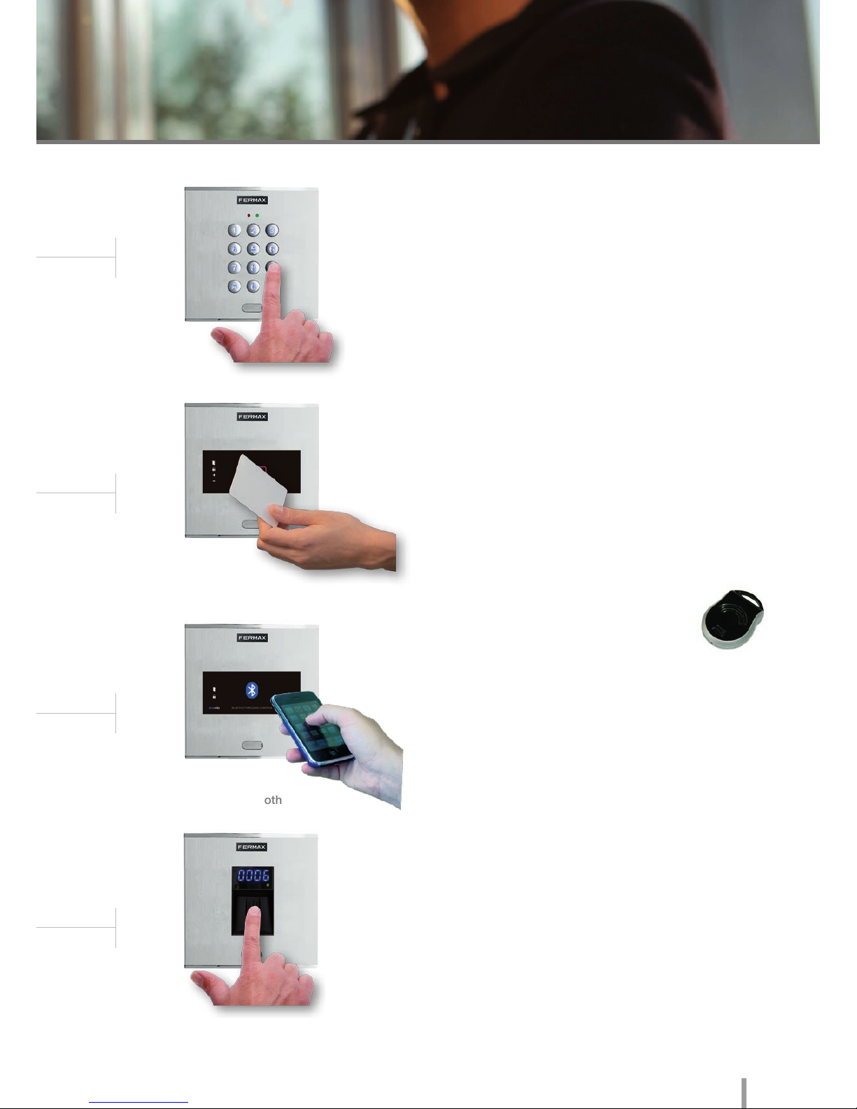
KEYPAD. The user should enter a code on the keypad. It is the
most economical model as it does not use identifiers. The same
code can be used by various users.
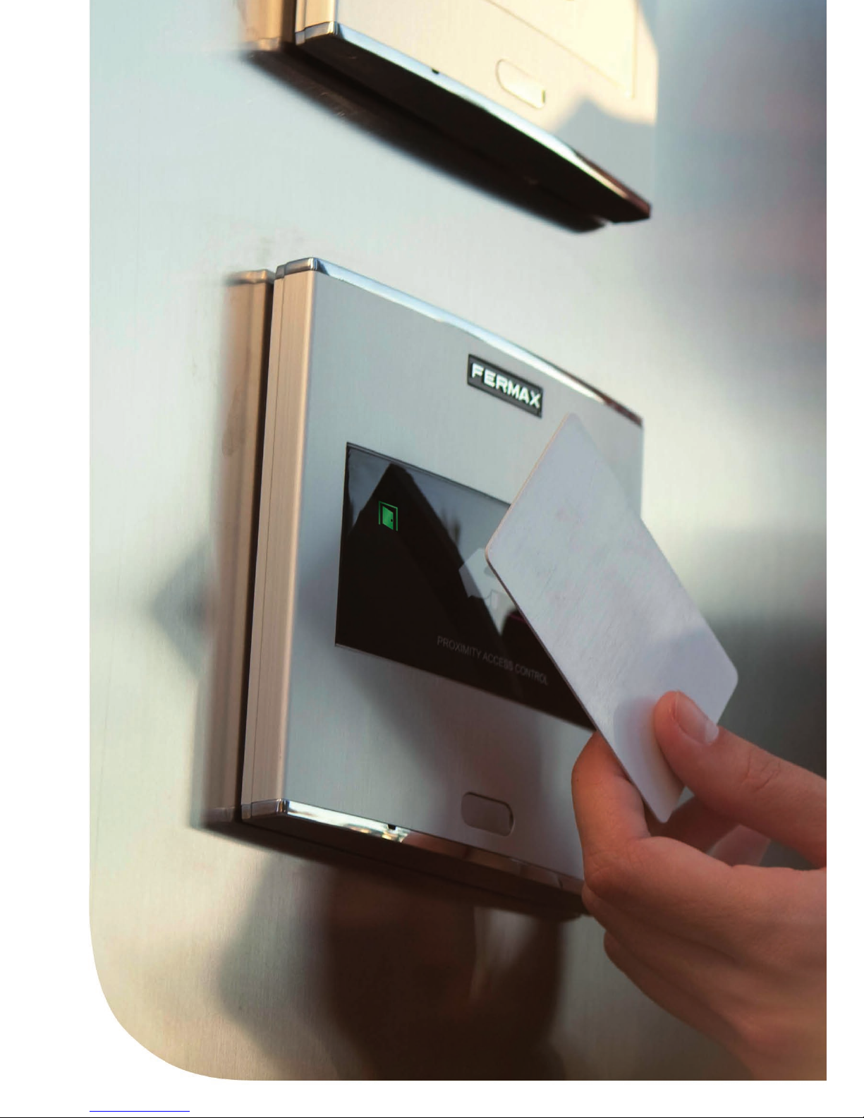
PROXIMITY. The identifier is a card (similar to a credit card)
or a proximity keyring. The identifier is swiped by the reader at
a distance of several centimetres. The reading is facilitated by
means of radio frequency data transmission.
BLUETOOTH. Access control functions by using mobile phones
with Bluetooth technology. The telephone system itself identifies
the user. The advantage of this system is the reader's operating
distance, which makes it very useful for vehicle and pedestrian
access.
BIOMETRIC FINGERPRINT. Biometric fingerprint access
reader with sensor. Identifies the user by their fingerprint (feature
which is unrepeatable and unique to each person), offering a
greater level of security than any other system using another
type of identifier.
RADIO FREQUENCY. This technology
is mainly used in garage accesses given
the flexibility allowed by the large distance
between the identifier (control) and the receiver.
There are several types of technology, depending on the
interaction between the identifier and the reader.
Keypad
Proximity Reader
Bluetooth
Fingerprint
8 2011 ACCESS CONTROL
2011 ACCESS CONTROL 9
• Dimensions:
* Reader
* Flush Mounted Box
* Surface Box
• Environmental Protection (IP)
• Anti-Shock Protection (IK)
• Power Supply (V)
• Consumption (mA) s/lock-release
• Operating Temperature
130x128
115x114x45
130x128x33
54
07
12V (ac/dc)
40/110
-15º to 55º C
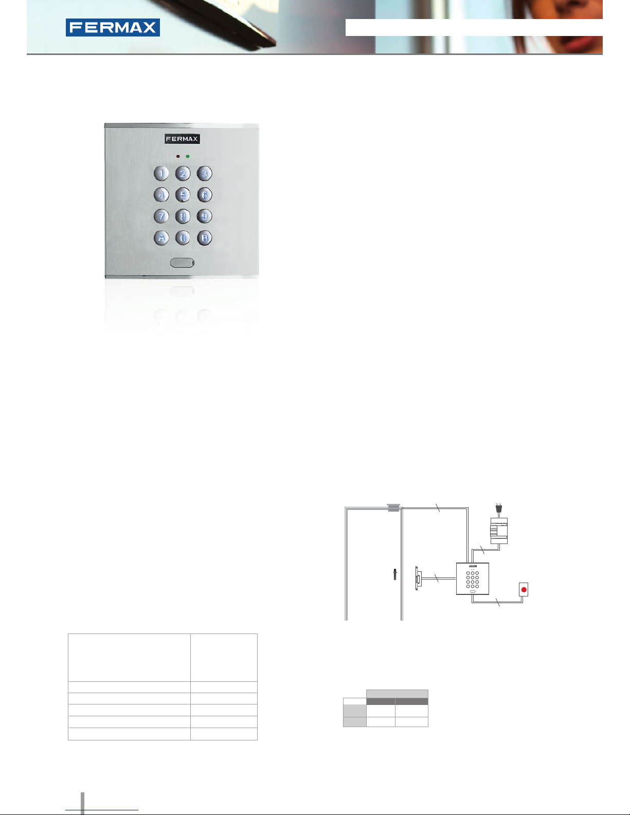
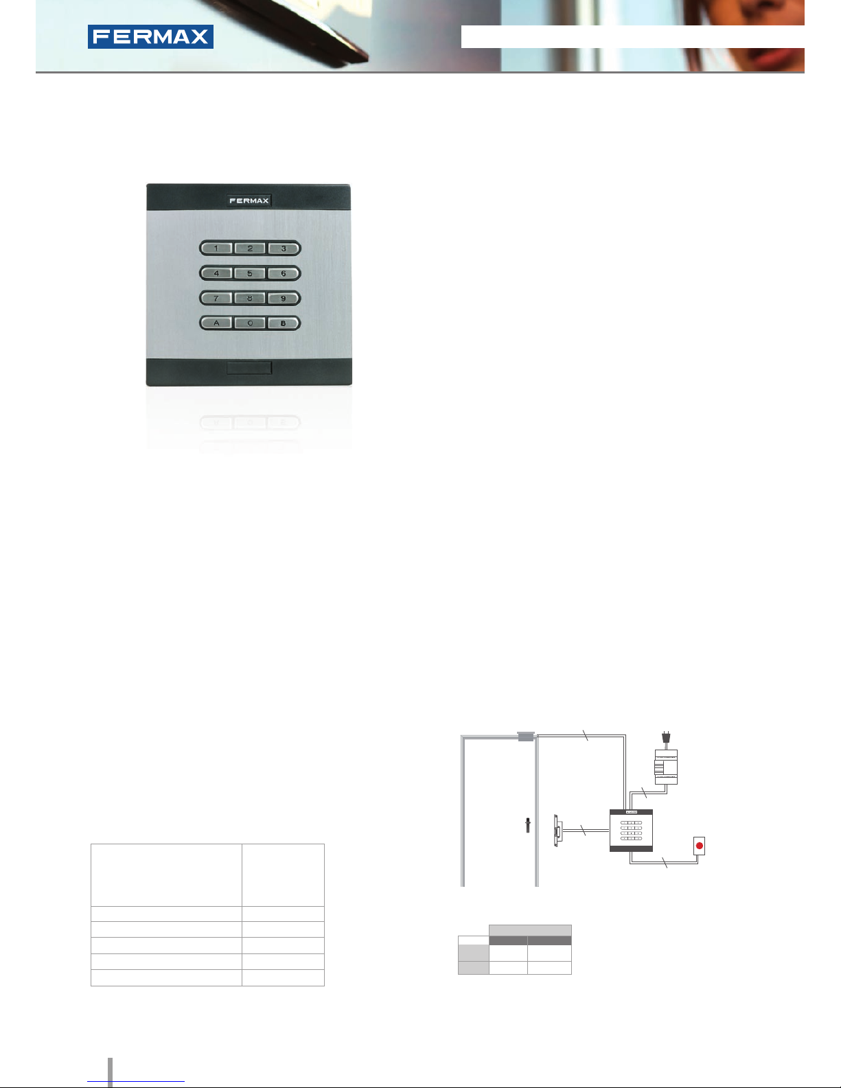
Ref.6991
Cityline Memokey
Keypad
• Access control keypad which allows the door to be
opened when a pre-programmed code of up to 6 digits
is entered.
• Capacity: up to 100 user codes.
• Length 4 to 6 digits.
• Integrated within the Cityline aluminum panel.
• Flush mounted (ref.8948, including box) or surface
installation (ref.7061, optional).
• Recommended for interiors and exteriors.
• Reader and controller integrated within the same module.
• Acoustic confirmation tone which sounds when a
button is pressed. Acoustic and visual confirmation
with LEDs showing if a code has been accepted/rejected.
• Blue backlit zamak keypad with status LED.
TECHNICAL FEATURES
INSTALLATION
PROGRAMMING
• 2A relay lock-release activation (NA, NC).
Programmable between 1 and 99 secs or bistable.
• Exit button input.
• Free access button input (trades).
• Auxiliary Open Collector Output (150mA max) to
indicate a vandalism attempt or open/forced door.
• Each code can activate 2 relays at the same time.
The keypad is located in the exterior area. The rest of the
devices are connected to this module and installed in the
building's interior: power supply and lock-release. An exit
button can be used optionally.
Programming from the same keypad using
a master code.
SPECIFICATIONS
Dimensions: (horizontal)x(vertical)x(depth) mm
Lock-Releases
Exit Button
Power Supply
Ref.6991
230Vac
2
2
2
2
STAND-ALONE
12Vdc
12Vac
30708
3071
2888
2880
* Door lock recommended.
Normal
References
Reinforced

2011 ACCESS CONTROL 9
2011 ACCESS CONTROL 9
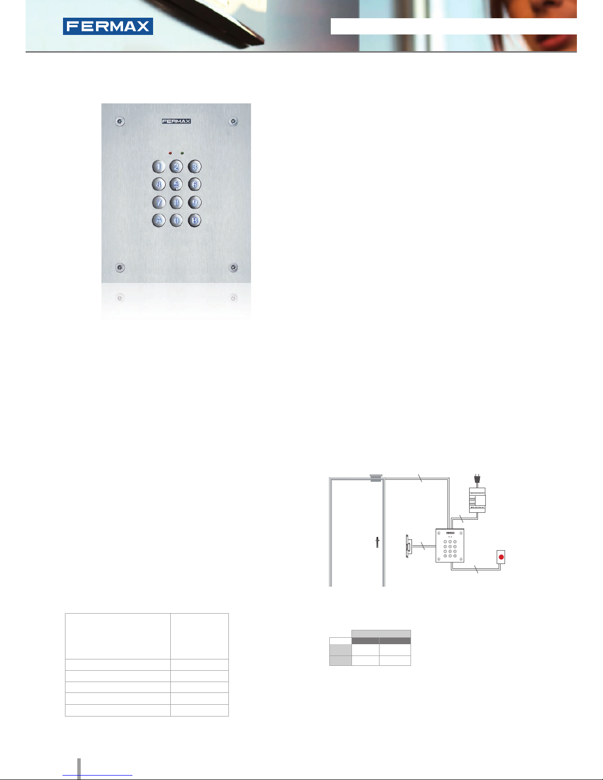
W Skyline Memokey
Ref.7438
Keypad
• Access control keypad module to be installed on
Skyline audio/video door entry system panels.
• Lock release on entering a code with up to 6 pre-
programmed digits.
• Capacity: up to 100 user codes.
• Length 4 to 6 digits.
• Blue backlit zamak keypad with status LEDs.
• Recommended for interior and exterior use.
• Reader and controller integrated within the same module.
• Acoustic confirmation tone which sounds when a
button is pressed. Acoustic and visual confirmation
with LEDs showing if a code has been accepted/
rejected.
TECHNICAL FEATURES
INSTALLATION
PROGRAMMING
• 2A relay lock-release activation (NA, NC).
Programmable from 1 and 99 seconds or bistable.
• Exit button input.
• Free access button input (trades).
• Auxiliary Open Collector Output (150mA max) to
indicate a vandalism attempt or open/forced door.
• Each code can activate 2 relays at the same time.
The electronic or video door entry system panels are located
in the building's exterior. The panel can be configured in
an intuitive manner using the memokey module for greater
ease of use and access security. The rest of the devices
are connected to this module and installed in the building's
interior: power supply and lock-release. An exit button can
be used optionally.
Programming from the same keypad using
a master code.
SPECIFICATIONS
Dimensions: (horizontal)x(vertical)x(depth) mm
• Reader Dimensions
• Environmental Protection (IP)
* Anti-Shock Protection (IK)
• Power Supply (V)
• Consumption (mA) s/lock-release
• Operating Temperature
105,2x95
54
07
12V (ac/dc)
40/110
-15º to 55º C
2
Lock-Releases
Exit Button
Power Supply
Ref. 7438
230Vac
2
2
2
STAND-ALONE
12Vdc
12Vac
30708
3071
2888
2880
* Door lock recommended.
Normal
References
Reinforced
10 2011 ACCESS CONTROL
2011 ACCESS CONTROL 11
City Classic
Memokey
Ref.3610
Keypad
• Access control keypad which allows the door to be
opened when a pre-programmed code of up to 6 digits
is entered.
• Capacity: up to 100 user codes.
• Length 4 to 6 digits.
• Integrated within an aluminum City Classic panel.
• Flush mounted (ref.8948, including box) or surface
installation (ref.8951, optional).
• Recommended for interior and exterior use.
• Reader and controller integrated within the same module.
• Confirmation tone when a button is pressed or to
indicate that the code entered has been accepted/
rejected.
TECHNICAL FEATURES
INSTALLATION
PROGRAMMING
• 2A relay lock-release activation (NA, NC).
Programmable at from 1 and 99 seconds or bistable.
• Exit button input.
• Free access button input (trades).
• Auxiliary Open Collector Output (150mA max) to
indicate a vandalism attempt or open/forced door.
• Each code can activate 2 relays at the same time.
The keypad is located in the exterior area. The rest of the
devices are connected to this module and installed in the
building's interior: power supply and lock-release. An exit
button can be used optionally.
Programming from the same keypad using
a master code.
SPECIFICATIONS
Dimensions: (horizontal)x(vertical)x(depth) mm
• Dimensions:
* Reader
* Flush Mounted Box
* Surface Box
• Environmental Protection (IP)
* Anti-Shock Protection (IK)
• Power Supply (V)
• Consumption (mA) s/lock-release
• Operating Temperature
130x128
115x114x45
130x128x33
43
07
12V (ac/dc)
6/60
0º to 70º C
Lock-Releases
Exit Button
Power Supply
Ref.3610
230Vac
2
2
2
2
STAND-ALONE
12Vdc
12Vac
30708
3071
2888
2880
* Door lock recommended.
Normal
References
Reinforced

2011 ACCESS CONTROL 11
2011 ACCESS CONTROL 11
City Classic CR
Memokey
Ref.3620 + Ref.3621
Keypad
• Access control keypad which allows the door to be opened
when a pre-programmed code of up to 6 digits is entered.
• Capacity for up to 100 user codes.
• Length 4 to 6 digits.
• Confirmation tone sounds when a button is pressed and to
indicate if the code entered has been accepted/rejected.
• Reader (ref.3620) and controller (ref.3621) in two
independent modules.
• The controller is installed in the building's interior near the
power supply and lock-release.
• The metallic box is included with the controller.
• Flush mounted (ref.8948, including box) or surface
installation (ref.8951, optional).
• A second keypad CR can be added in the building's
interior.
• Maximum distance between reader and controller of 100m.
• Reader and controller not integrated within the same
module.
TECHNICAL FEATURES
INSTALLATION
PROGRAMMING
• 2A relay lock-release activation (NA, NC).
Programmable at from 1 and 99 seconds or bistable.
• Exit button input.
• Free access button input (trades).
• Auxiliary Open Collector Output (150mA max) to
indicate a vandalism attempt or open/forced door.
• Each code can activate 2 relays at the same time.
The CR keypad is located in the exterior of the building and
is connected to the controller in the interior in the same way
as the rest of the device (power supply and lock-release).
An exit button can be used optionally.
Programming from the same keypad using
a master code.
SPECIFICATIONS
Dimensions: (horizontal)x(vertical)x(depth) mm
• Dimensions:
* Reader
* Flush Mounted Box
* Surface Box
* Metallic Box
• Environmental Protection (IP)
* Anti-Shock Protection (IK)
• Power Supply (V)
• Consumption (mA) s/lock-release
• Operating Temperature
130x128
115x114x45
130x128x33
154x203x50
43
07
12V (ac/dc)
6/60
0º to 70º C
Lock-Releases
Exit Button
Power Supply
Ref.3621
Ref.3620
230Vac
2
2
6
STAND-ALONE
12Vdc
12Vac
30708
3071
2888
2880
* Door lock recommended.
Normal
References
Reinforced
12 2011 ACCESS CONTROL
2011 ACCESS CONTROL 13
Marine Memokey
Ref.4699
Keypad
• Access control keypad which allows the door to be
opened when a pre-programmed code of up to 6
digits is entered.
• Capacity: up to 100 user codes.
• Length 4 to 6 digits.
• Integrated within a 2.5mm stainless steel Marine panel.
• Flush mounted (ref.4641, including
box) or surface installation (ref.4701, optional).
• Recommended for interior and exterior use.
• Reader and controller integrated within the same module.
• Acoustic confirmation tone which sounds when a
button is pressed. Acoustic and visual confirmation
with LED’s showing if a code has been accepted/
rejected.
• Blue backlit zamak keypad with status LEDs.
TECHNICAL FEATURES INSTALLATION
PROGRAMMING
• 2A relay lock-release activation (NA, NC).
Programmable at from 1 and 99 seconds or bistable.
• Exit button input.
• Free access button input (trades).
• Auxiliary Open Collector Output (max. 150mA) to
indicate a vandalism attempt or open/forced door.
• Each code can activate 2 relays at the same time.
The keypad is located in the exterior area. The rest of the
devices are connected to this module and installed in the
building's interior: power supply and lock-release. An exit
button can be used optionally.
Programming from the same keypad using
a master code.
SPECIFICATIONS
Dimensions: (horizontal)x(vertical)x(depth) mm
• Dimensions:
* Reader
* Flush Mounted Box
* Surface Box
• Environmental Protection (IP)
• Anti-Shock Protection (IK)
• Power Supply (V)
• Consumption (mA) S/lock-release.
• Operating Temperature
150x180
130x160x55
154x184x55
54
09
12V (ac/dc)
40/110
-15º to 55º C
Lock-Releases
Exit Button
Power Supply
Ref.4699
230Vac
2
2
2
2
STAND-ALONE
12Vdc
12Vac
30708
3071
2888
2880
* Door lock recommended.
Normal
References
Reinforced
2011 ACCESS CONTROL 13
2011 ACCESS CONTROL 13
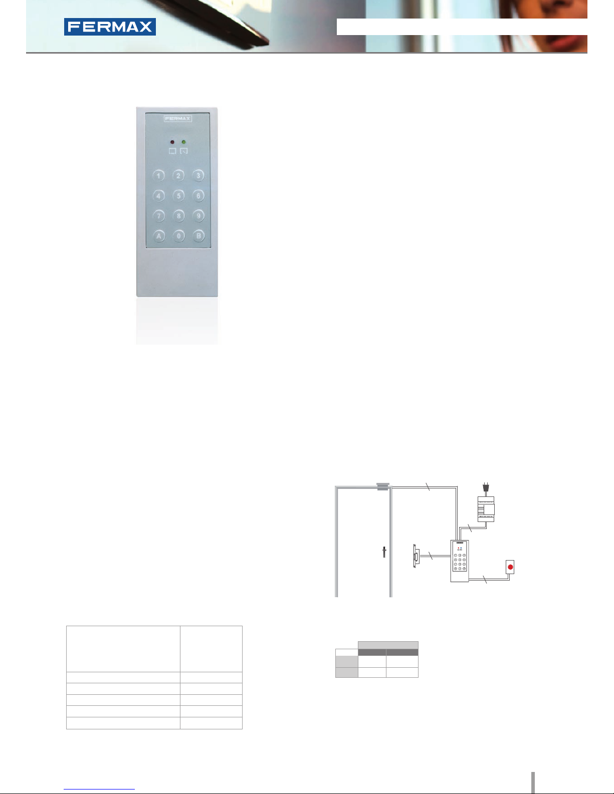
Loft Memokey
Ref.4540
Keypad
• Access control keypad which allows the door to be
opened when a pre-programmed code of up to 6
digits is entered.
• Membrane keypad finished in texturised ABS plastic
with status LEDs.
• Surface installation.
• Capacity: up to 100 user codes.
• Length 4 to 6 digits.
• Recommended for interior use.
• Includes 50cm of wiring.
• Reader and controller integrated within the same module.
• Acoustic confirmation tone which sounds when a
button is pressed. Acoustic and visual confirmation
with LED’s showing if a code has been accepted/
rejected.
TECHNICAL FEATURES INSTALLATION
PROGRAMMING
• 2A relay lock-release activation (NA, NC).
Programmable at from 1 and 99 seconds or
bistable.
• Exit button input.
• Free access button input (trades).
• Auxiliary Open Collector Output (max. 150 mA) to
indicate a vandalism attempt or open/forced door.
• Tamper proof to indicate vandalism attempts.
The keypad is located in the exterior area. The rest of
the devices are connected to this module and they are
installed in the building's interior: power supply and lock-
release. An exit button can be used optionally.
Programming from the same keypad using
a master code.
SPECIFICATIONS
Dimensions: (horizontal)x(vertical)x(depth) mm
• Dimensions:
* Reader
* Flush Mounted Box
* Surface Box
• Environmental Protection (IP)
• Anti-Shock Protection (IK)
• Power Supply (V)
• Consumption (mA) s/lock-release.
• Operating Temperature
60x130x23
Not required
Not required
66
06
12V (ac/dc)
20/70
0º to 70º C
Lock-Releases
Exit Button
Power Supply
Ref.4540
230Vac
2
2
2
2
STAND-ALONE
12Vdc
12Vac
30708
3071
2888
2880
* Door lock recommended.
Normal
References
Reinforced
14 2011 ACCESS CONTROL
2011 ACCESS CONTROL 15
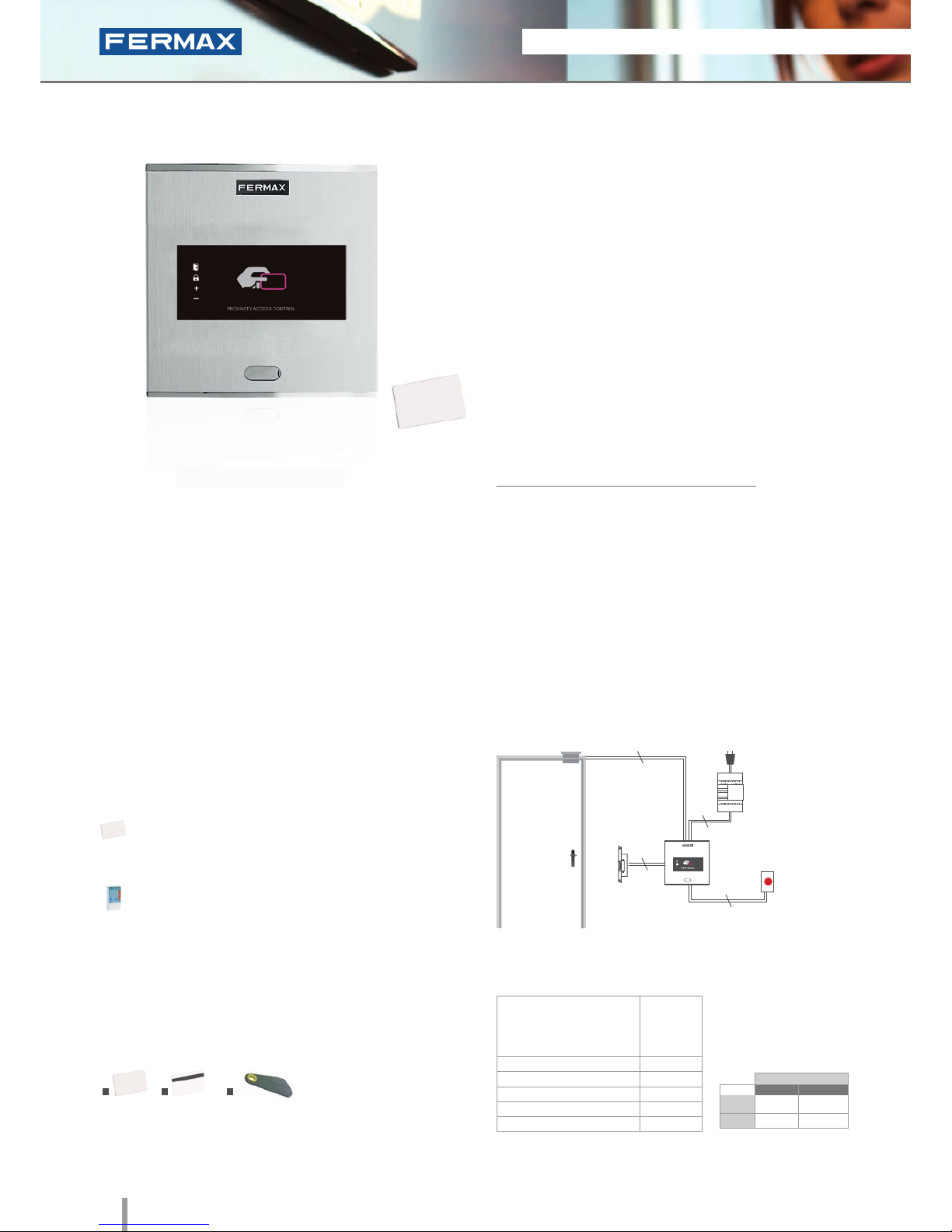
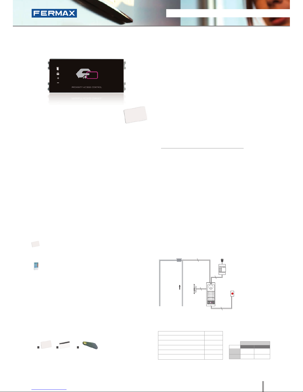
Cityline Private
Ref.6992
Proximity
• Access control reader which allows the door to be opened
by swiping the proximity card or keyring. Only authorised
cards or keyrings activate the device. Physical contact is not
necessary.
• Integrated within the Cityline aluminum panel.
• Flush mounted (ref.8948, including box) or surface
installation (ref.7061, optional).
• Recommended for interior and exterior use.
• Reader and controller integrated within the same module.
• Can operate as a stand-alone or centralised system.
Congurable between dipswitches (SW2).
Configuration as a STAND-ALONE system:
• Capacity: up to 400 user cards or keyrings.
• Acoustic and visual confirmation using LEDs which
advise if the card swiped has been accepted/rejected.
Dimensions: (horizontal)x(vertical)x(depth) mm
INSTALLATION
SPECIFICATIONS
• Dimensions:
* Reader
* Flush Mounted Box
* Surface Box
• Environmental Protection (IP)
• Anti-Shock Protection (IK)
• Power Supply (V)
• Consumption (mA) S/lock-release
• Operating Temperature
130x128
115x114x45
130x128x33
54
07
12V (ac/dc)
90
-15º to 55ºC
TECHNICAL FEATURES
• Does not require physical contact.
5cm (card) or 1.5cm (keyring) reading distance.
• Acoustic and visual status data.
• Status LEDs (help in programming and determining
status).
• Manual programming (using master card or keyring)
or via PC software (card activation/deactivation).
• Door sensor and exit button control.
• Relay output.
• Relay lock-release activation with programmable
time. Programmable from 1 to 99 seconds.
IDENTIFIERS
1. Card without magnetic strip (ref.23361); 2. Card with magnetic strip
(ref.2336); 3. Proximity keyring (ref.44501).
The reader is located in the exterior area. The rest of the
devices are connected to this module and they are installed in
the building's interior: power supply and lock-release. An exit
button can be used optionally.
Lock-Releases
Exit Button
Power Supply
Ref.6992
230Vac
2
2
2
2
PROGRAMMING
This can be done in 3 ways:
Master card: The first time the power supply is
connected, the system waits for a proximity card to be
swiped. This is then considered the "master card".
Keypad: Recommended if we want to deactivate
faulty cards.
PC Software: For managing user activation/
deactivations.
The WINPROX software can be downloaded from
www.fermax.com
1 2
3
STAND-ALONE
12Vdc
12Vac
30708
3071
2888
2880
* Door lock recommended.
Normal
References
Reinforced
2011 ACCESS CONTROL 15
2011 ACCESS CONTROL 15
• Access control reader which allows the door to be opened
by swiping the proximity card or keyring. Only authorised
cards or keyrings activate the device. Physical contact is
not necessary.
• Access control module to be integrated within Skyline
audio/video door entry system panels.
• Recommended for interior and exterior use.
• Reader and controller integrated within the same module.
• Can operate as a stand-alone or centralised system.
Congurable between dipswitches (SW2).
Configuration as a STAND-ALONE system:
• Capacity: up to 400 user cards or keyrings.
• Acoustic and visual confirmation using LEDs which
advise if the card swiped has been accepted/ rejected.
INSTALLATION
The electronic or video door entry system panels are located
in the building's exterior. The panel can be configured in an
intuitive manner using the private module for greater ease of
use and access security. The rest of the devices are connected
to this module and they are installed in the building's interior:
power supply and lock-release. An exit button can be used
optionally.
V Skyline Private
Ref.7440
Proximity
TECHNICAL FEATURES
• Does not require physical contact.
5cm (card) or 1.5cm (keyring) reading distance.
• Acoustic and visual status data.
• Status LEDs (help in programming and determining
status).
• Manual programming (using master card or keyring)
or via PC software (card activation/deactivation).
• Door sensor and exit button control.
• Relay output.
• Relay lock-release activation with programmable
time. Programmable at 1 to 99 secs.
Lock-Releases
Exit Button
Power Supply
Ref.7440
230Vac
2
2
2
2
SPECIFICATIONS
• Reader Dimensions:
• Environmental Protection (IP)
• Anti-Shock Protection (IK)
• Power Supply (V)
• Consumption (mA) S/lock-release
• Operating Temperature
105.2X47.5
54
07
12V (ac/dc)
90
-15º to 55ºC
PROGRAMMING
This can be done in 3 ways:
Master card: The first time the power supply is
connected, the system waits for a proximity card to be
swiped. This is then considered the "master card".
Keypad: Recommended if we want to deactivate
faulty cards.
PC Software: For managing user activation/
deactivations.
The WINPROX software can be downloaded from
www.fermax.com
IDENTIFIERS
1. Card without magnetic strip (ref.23361); 2. Card with magnetic strip
(ref.2336); 3. Proximity keyring (ref.44501).
Dimensions: (horizontal)x(vertical)x(depth) mm
1 2
3
STAND-ALONE
12Vdc
12Vac
30708
3071
2888
2880
* Door lock recommended.
Normal
References
Reinforced

16 2011 ACCESS CONTROL
2011 ACCESS CONTROL 17
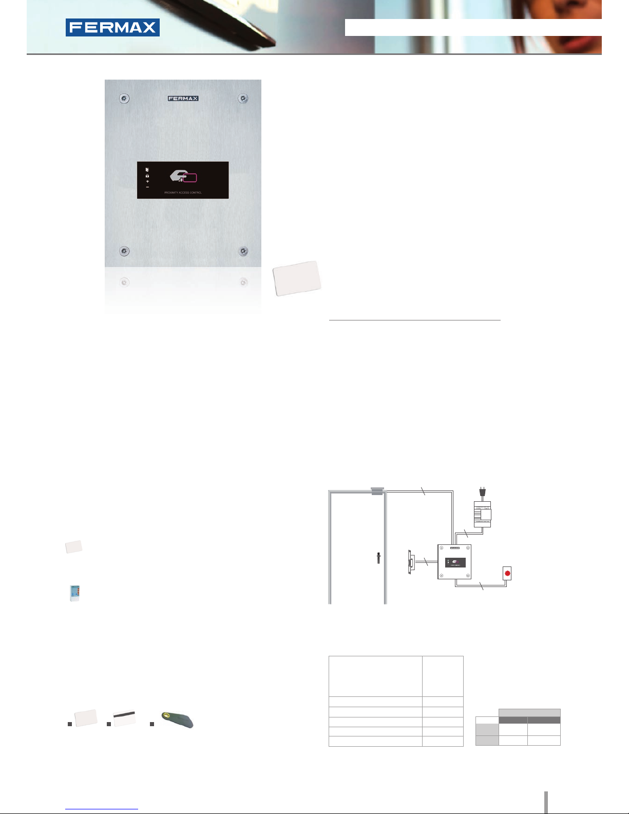
City Classic Private
Ref.2347
Proximity
• Access control reader which allows the door to be opened
by swiping the proximity card or keyring . Only authorised
cards or keyrings activate the device. Physical contact is
not necessary.
• Capacity: up to 400 user cards or keyrings.
• Integrated within the City Classic aluminum panel.
• Flush mounted (ref.8948, including box) or surface
installation (ref.8951, optional).
• Recommended for interior and exterior use.
• Reader and controller integrated within the same module.
• Acoustic and visual confirmation using LEDs which
advise if the card presented has been accepted/rejected.
Dimensions: (horizontal)x(vertical)x(depth) mm
INSTALLATION
TECHNICAL FEATURES
• Does not require physical contact.
3cm (card) or 1cm (keyring) reading distance.
• Acoustic and visual status data.
• Manual programming (using master card or keyring)
or via PC software (card activation/deactivation).
• Door sensor and exit button control.
• Relay output.
• Relay lock-release activation with programmable time.
Programmable from 1 to 99 seconds.
• Status LEDs (help in programming and determining
status).
SPECIFICATIONS
• Dimensions:
* Reader
* Flush Mounted Box
* Surface Box
• Environmental Protection (IP)
• Anti-Shock Protection (IK)
• Power Supply (V)
• Consumption (mA) S/lock-release
• Operating Temperature
130x128
115x114x45
130x128x33
43
07
12V (ac/dc)
80/120
0º to 60ºC
The reader is located in the exterior area. The rest of the
devices are connected to this module and they are installed in
the building's interior: power supply and lock-release. An exit
button can be used optionally.
Lock-Releases
Exit Button
Power Supply
Ref.2347
230Vac
2
2
2
2
PROGRAMMING
This can be done in 3 ways:
Master card: The first time the power supply is
connected, the system waits for a proximity card to be
swiped. This is then considered the "master card".
Keypad: Recommended if we want to deactivate
faulty cards.
PC Software: For managing user activation/
deactivations.
The WINPROX software can be downloaded from
www.fermax.com
IDENTIFIERS
1. Card without magnetic strip (ref.23361); 2. Card with magnetic strip
(ref.2336); 3. Proximity keyring (ref.44501).
1 2
3
STAND-ALONE
12Vdc
12Vac
30708
3071
2888
2880
* Door lock recommended.
Normal
References
Reinforced
2011 ACCESS CONTROL 17
2011 ACCESS CONTROL 17
• Access control reader which allows the door to be opened
by swiping the proximity card or keyring. Only authorised
cards or keyrings activate the device. Physical contact is
not necessary.
• Integrated within a 2.5mm Marine stainless steel panel.
• Flush mounted (ref.4641, including box) or surface
installation (ref.4701, optional).
• Recommended for interior and exterior use.
• Reader and controller integrated within the same module.
• Can operate as a stand-alone or centralised system.
Congurable between dipswitches (SW2).
Configuration as a STAND-ALONE system:
• Capacity: up to 400 user cards or keyrings.
• Acoustic and visual confirmation using status LEDs
which advise if the card swiped has been accepted/
rejected.
INSTALLATION
The reader is located in the exterior area. The rest of the devices
are connected to this module and installed in the building's
interior: power supply and lock-release. An exit button can be
used optionally.
SPECIFICATIONS
Marine Private
Ref.5472
Proximity
TECHNICAL FEATURES
• Does not require physical contact.
4cm (card) or 1cm (keyring) reading distance.
• Acoustic and visual status data.
• Manual programming (using master card or keyring)
or via PC software (card activation/deactivation).
• Door sensor and exit button control.
• Relay output.
• Relay lock-release activation with programmable
time. Programmable from 1 to 99 seconds.
• Status LEDs (help in programming and determining
status).
• Dimensions:
* Reader
* Flush Mounted Box
* Surface Box
• Environmental Protection (IP)
• Anti-Shock Protection (IK)
• Power Supply (V)
• Consumption (mA) S/lock-release
• Operating Temperature
150x180
130x160x55
154x184x55
54
09
12V (ac/dc)
90
-15º to 55ºC
Lock-Releases
Exit Button
Power Supply
Ref.5472
230Vac
2
2
2
2
PROGRAMMING
This can be done in 3 ways:
Master card: The first time the power supply is
connected, the system waits for a proximity card to be
swiped. This is then considered the "master card".
Keypad: Recommended if we want to deactivate
faulty cards.
PC Software: For managing user activations/
deactivations.
The WINPROX software can be downloaded from
www.fermax.com.
IDENTIFIERS
1. Card without magnetic strip (ref.23361); 2. Card with magnetic strip
(ref.2336); 3. Proximity keyring (ref.44501).
Dimensions: (horizontal)x(vertical)x(depth) mm
1 2
3
STAND-ALONE
12Vdc
12Vac
30708
3071
2888
2880
* Door lock recommended.
Normal
References
Reinforced
18 2011 ACCESS CONTROL
2011 ACCESS CONTROL 19
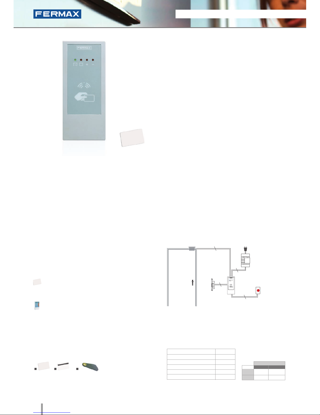
Loft Private
Ref.4530
Proximity
• Access control reader which allows the door to be opened
by swiping the proximity card or keyring. Only authorised
cards or keyrings activate the device. Physical contact is
not necessary.
• Capacity: up to 400 user cards or keyrings.
• Module finished in textured ABS plastic.
• Surface installation.
• Recommended for interior use.
• Includes 50 cm of wiring.
• Reader and controller integrated within the same module.
• Acoustic and visual confirmation using LEDs which
advise if the card swiped has been accepted/rejected.
Dimensions: (horizontal)x(vertical)x(depth) mm
INSTALLATION
The reader is located in the exterior area. The rest of the
devices are connected to this module and they are installed in
the building's interior: power supply and lock-release. An exit
button can be used optionally.
TECHNICAL FEATURES
• Does not require physical contact.
4 cm (card) or 1 cm (keyring) reading distance.
• Acoustic and visual status data.
• Manual programming (using master card or keyring)
or via PC software (card activation/deactivation).
• Door sensor and exit button control.
• Relay output.
• Relay lock-release activation with programmable
time. Programmable from 1 to 99 seconds.
• Status LED (help in programming and determining
status).
SPECIFICATIONS
• Reader Dimensions
• Environmental Protection (IP)
• Anti-Shock Protection (IK)
• Power Supply (V)
• Consumption (mA) S/lock-release
• Operating Temperature
60x130x23
66
06
12V (ac/dc)
45/75
0º to 60ºC
Lock-Releases
Exit Button
Power Supply
Ref.2347
230Vac
2
2
2
2
PROGRAMMING
This can be done in 3 ways:
Master card: The first time the power supply is
connected, the system waits for a proximity card to be
swiped. This is then considered the "master card".
Keypad: Recommended if we want to deactivate
faulty cards.
PC Software: For managing user activation/
deactivations. The WINPROX software can be
downloaded from www.fermax.com
STAND-ALONE
IDENTIFIERS
1. Card without magnetic strip (ref.23361); 2. Card with magnetic strip
(ref.2336); 3. Proximity keyring (ref.44501).
1 2
3
12Vdc
12Vac
30708
3071
2888
2880
* Door lock recommended.
Normal
References
Reinforced

2011 ACCESS CONTROL 19
2011 ACCESS CONTROL 19
Identifiers
Maintenance
Credit Card Format white PVC material.
Each device comes with an identier to allow
it to setup in the system. It does not require
maintenance or batteries.
ASK 125KHz Modulation. Code Protocol.
Allows it to be personalized with the users
logo and photograph using various printing
options. See prices and commercial
references.
Dimensions: 85x54mm.
Proximity Card without
magnetic strip
Proximity Card with
magnetic strip
Proximity Keyring
Ref.23361
Ref.2336
Ref.44501
Similar to the above, but also incorporates
a high coercivity magnetic strip for other
functions.
To carry the identifier along with traditional
keys. Each device comes with an identier
to allow it to be set up in the system (with
exclusive identifiers).
The proximity reader is used in residential
settings given its ease of use.
Reduced dimensions: 25x52mm.
For maintenance service and information
management in PRIVATE systems. Allows you to
receive and compile comprehensive information
on the READER's users.
It can be downloaded from www.fermax.com
WINPROX allows you to manage the access
control system's autonomous proximity readers,
their users and cards, manage incidents online,
control IP cameras, generate reports, etc in an
easy intuitive manner.
With WINPROX you can dene various access
readers, activate or deactivate users, assign
various cards to a single user, configure access
permission for various users on a single system,
manage card expiry, import and export user lists
to excel, etc.
PC Programming Software:
WINPROX
Recommended for maintenance work
and to manually deactivate the faulty card
from the reader itself.
Also allows you to carry out all
programming operations using simple
commands.
PC Programming Kit for Private Loft
readers.
Includes a PC and CD interface with
WINPROX software.
Programming Keypad
Private
Programming Kit
PC Loft
Ref.2306
Ref.3625
STAND-ALONE
20 2011 ACCESS CONTROL
2011 ACCESS CONTROL 21
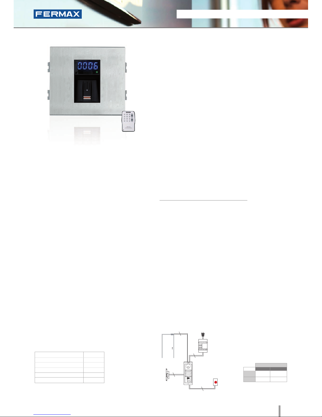
Cityline Fingerprint
Ref.6959
Fingerprint
• Biometric access fingerprint reader with capacitive sensor.
Identifies the user by way of their fingerprint (a unique,
unrepeatable characteristic). With built-in proximity reader
which functions as follows:
- Some people have fingerprints without the necessary
information for authorization in a biometric system. This applies
to 1% of the population. In these cases, use integrated
Proximity.
- Security mode: activates dual security, (Fingerprint+Card) for
the same User.
• Integrated within the Cityline aluminum panel.
• Flush mounted (ref.8948, including box) or surface
installation (ref.7061, optional).
• Recommended for interior and exterior use.
• Reader and controller integrated within the same module.
• Can run as an stand-alone or centralised system
(dipswitch configurable).
Configuration as a STAND-ALONE system:
• Capacity (no. users):
- 4.500 users in 1 fingerprint per person mode.
- 2.970 users in 2 fingerprints per person mode.
• Acoustic and visual confirmation using status and display
LEDs which indicate if a fingerprint has been accepted or
rejected.
• To ensure the ngerprint is read correctly, slide your nger along
the reader with a downwards movement (from top to bottom),
at a uniform speed and exerting slight pressure.
• Includes a software CD and infrared remote keypad.
PROGRAMMING
TECHNICAL FEATURES
• Relay lock-release activation. Programmable from
01 to 99 seconds.
• Acoustic and visual status data.
• Reader with 2 status LEDs and a 7 segment 4 digit
display (helps with programming and status data).
• Manual programming using the infrared remote
control included or via PC software (card activation/
deactivation of fingerprints).
• Special Functions: free ngerprint button (trades) and
unblock fingerprint (lock-release always activated).
• Door sensor and exit button control.
• Auxiliary Relay for other Functions. Door alarm and
forced door, panic alarm or intruder alarm (incorrect
fingerprint).
• Allows keypad connection for Security Mode
operation: in this case, the dual security would be
Fingerprint+Code, for the same User.
Programming can be done manually or by PC. The system
is programmed with a master print (Administrator) and a
remote infrared keypad. The PC programming software can be
downloaded from www.fermax.com. The «Clone» option is available:
it is used to copy all data entered in one reader into another.
NOTE: See
“Installation
diagrams for
stand-alone
in network
fingerprint
readers”.
Built-in Proximity reader
The fingerprint reader is located in the exterior area. The
rest of the devices are connected to this module and they
are installed in the building's interior: power supply and
lock-release. An exit button can be used optionally.
INSTALLATION
Dimensions: (horizontal)x(vertical)x(depth) mm
SPECIFICATIONS
• Dimensions:
* Reader
* Flush Mounted Box
* Surface Box
• Environmental Protection (IP)
• Anti-Shock Protection (IK)
• Power Supply (V)
• Consumption (mA) S/lock-release
• Operating Temperature
130x128
115x114x45
130x128x33
43
07
12V (ac/dc)
118/173
-10º to 55ºC
Lock-Releases
Exit Button
Power Supply
Ref.6959
230Vac
2
2
2
2
024
STAND-ALONE
* Door lock recommended.
12Vdc
12Vac
30708
3071
2888
2880
Normal
References
Reinforced
2011 ACCESS CONTROL 21
2011 ACCESS CONTROL 21
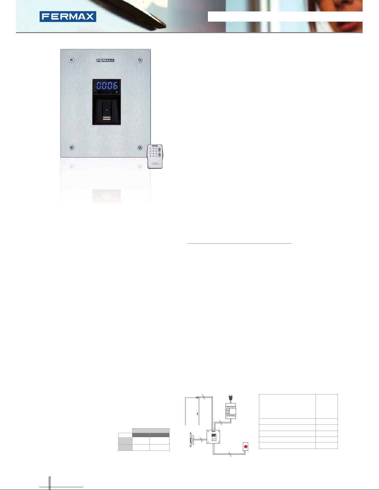
W Skyline Fingerprint
Ref.6989
Fingerprint
• Biometric access fingerprint reader with capacitive sensor.
Identifies the user by way of their fingerprint (a unique,
unrepeatable characteristic). With built-in proximity reader
which functions as follows:
- Some people have fingerprints without the necessary
information for authorization in a biometric system. This applies
to 1% of the population. In these cases, use integrated
Proximity.
- Security mode: activates dual security, (Fingerprint+Card) for
the same User.
• Access control module, to be integrated within Skyline
audio/video door-entry system panels.
• Recommended for interior and exterior use.
• Reader and controller integrated within the same module.
• Can operate as an stand-alone or centralised system
(dipswitch configurable).
Configuration as a STAND-ALONE system:
• Capacity (no. users):
- 4.500 users in 1 fingerprint per person mode.
- 2.970 users in 2 fingerprints per person mode.
• Acoustic and visual confirmation using status and
display LEDs which indicate if a fingerprint has been
accepted or rejected.
• To ensure the ngerprint is read correctly, slide your nger along
the reader with a downwards movement (from top to bottom),
at a uniform speed and exerting slight pressure.
• Includes a software CD and infrared remote keypad.
PROGRAMMING
TECHNICAL FEATURES
INSTALLATION
The electronic or video door-entry system panels are located in
the building's exterior. The panel can be configured in an intuitive
manner, including a fingerprint reader module for greater ease of
use and access security. The rest of the devices are connected to
this module and they are installed in the building's interior: power
supply and lock-release. An exit button can be used optionally.
Programming can be done manually or by PC. The system
is programmed with a master print (Administrator) and a
remote infrared keypad. The PC programming software
can be downloaded from www.fermax.com. The «Clone»
option is available: it is used to copy all data entered in
one reader into another.
• Relay lock-release activation Programmable from
01 to 99 seconds.
• Acoustic and visual status data.
• Reader with 2 status LEDs and a 7 segment 4 digit
display (helps with programming and status data).
• Manual programming using the infrared remote
control included or via PC software (card activation/
deactivation of fingerprints).
• Special Functions: free ngerprint button (trades) and
unblock fingerprint (lock-release always activated).
• Door sensor and exit button control.
• Auxiliary Relay for other Functions. Door alarm and
forced door, panic alarm or intruder alarm (incorrect
fingerprint).
• Allows keypad connection for Security Mode
operation: in this case, the dual security would be
Fingerprint+Code, for the same User.
Lock-Releases
Exit Button
Power Supply
Ref.6989
230Vac
2
2
2
2
024
Dimensions: (horizontal)x(vertical)x(depth) mm
SPECIFICATIONS
• Dimensions:
• Environmental Protection (IP)
• Anti-Shock Protection (IK)
• Power Supply (V)
• Consumption (mA) s/lock-release
• Operating Temperature
105.2x95
43
07
12V (ac/dc)
118/173
-10º to 55ºC
Built-in Proximity reader
STAND-ALONE
12Vdc
12Vac
30708
3071
2888
2880
* Door lock recommended.
Normal
References
Reinforced
22 2011 ACCESS CONTROL
2011 ACCESS CONTROL 23
Marine Fingerprint
Ref.5474
Fingerprint
• Biometric access fingerprint reader with capacitive sensor.
Identifies the user by way of their fingerprint (a unique,
unrepeatable characteristic). With built-in proximity reader
which functions as follows:
- Some people have fingerprints without the necessary
information for authorization in a biometric system. This applies
to 1% of the population. In these cases, use integrated
Proximity.
- Security mode: activates dual security, (Fingerprint+Card) for
the same User.
• Integrated within a 2.5mm stainless steel Marine panel.
• Flush mounted (ref.4641, including box) or surface
installation (ref.4701, optional).
• Recommended for interior and exterior use.
• Reader and controller integrated within the same module.
• Can operate as a stand-alone or centralised system
(dipswitch configurable).
Configuration as a STAND-ALONE system:
• Capacity (no. users):
- 4.500 users in 1 fingerprint per person mode.
- 2.970 users in 2 fingerprints per person mode.
• Acoustic and visual confirmation using status and display
LEDs which indicate if a fingerprint has been accepted or
rejected.
• To ensure the ngerprint is read correctly, slide your nger along
the reader with a downwards movement (from top to bottom),
at a uniform speed and exerting slight pressure.
• Includes a software CD and infrared remote keypad.
PROGRAMMING
Programming can be done manually or by PC.
The system is programmed with a master print
(Administrator) and a remote infrared keypad. The PC
programming software can be downloaded from www.
fermax.com. The «Clone» option is available: it is used to
copy all data entered in one reader into another.
The fingerprint reader is located in the exterior area. The rest of the
devices are connected to this module and they are installed in the
building's interior: power supply and lock-release. An exit button
can be used optionally.
INSTALLATION
Dimensions: (horizontal)x(vertical)x(depth) mm
SPECIFICATIONS
• Dimensions:
* Reader
* Flush Mounted Box
* Surface Box
• Environmental Protection (IP)
• Anti-Shock Protection (IK)
• Power Supply (V)
• Consumption (mA) S/lock-release
• Operating Temperature
150x180
130x160x55
154x184x55
43
08
12V (ac/dc)
118/173
-10º to 55ºC
Lock-Releases
Exit Button
Power
Supply
Ref.5474
230Vac
2
2
2
2
024
STAND-ALONE
12Vdc
12Vac
30708
3071
2888
2880
* Door lock recommended.
Normal
References
Reinforced
TECHNICAL FEATURES
• Relay lock-release activation.
Programmable from 01 to 99 seconds.
• Acoustic and visual status data.
• Reader with 2 status LEDs and a 7 segment 4 digit
display (helps with programming and status data).
• Manual programming using the infrared
remote control included or via PC software (card
activation/deactivation of fingerprints).
• Special Functions: free ngerprint button (trades)
and unblock fingerprint (lock-release always
activated).
• Door sensor and exit button control.
• Auxiliary Relay for other Functions. Door alarm and
forced door, panic alarm or intruder alarm (incorrect
fingerprint).
• Allows keypad connection for Security Mode
operation: in this case, the dual security would be
Fingerprint+Code, for the same User.
Built-in Proximity reader
2011 ACCESS CONTROL 23
2011 ACCESS CONTROL 23
STAND-ALONE
12Vdc
12Vac
30708
3071
2888
2880
* Door lock recommended.
Normal
References
Reinforced
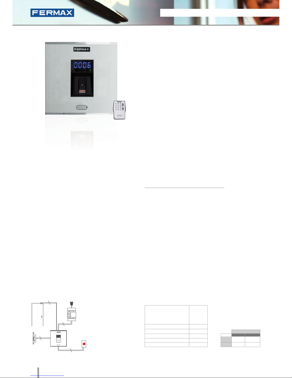
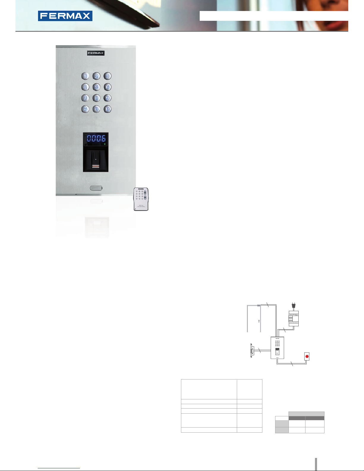
• There are a number of people whose ngerprints do not not have
the necessary information to be set up on a biometric system.
This applies to 1% of the population. In these cases, the use of an
alternative technology combined is recommended.
• Biometric access fingerprint reader with capacitive sensor.
Identifies the user by way of their fingerprint (unique and
unrepeatable characteristic). Built-in proximity reader. Reader also
includes a keypad. Functions as follows:
- For cases where ngerprints cannot be authorized, use integrated
Proximity or Keypad.
- Segurity mode: The reader includes a keypad for dual security
function: Fingerprint+Code, for the same User.
• Integrated in Cityline aluminium panel.
• Flush mounted (ref.8855, including box) or surface mounted
(ref.7065, optional).
• Recommended for interior and exterior use.
• Reader and controller integrated within the same module.
• Includes a software CD and infrared remote keypad.
PROGRAMMING
Programming can be done manually or via PC. In manual mode the
system is programmed using a master fingerprint (administrator)
and an infrared remote keypad. The PC programming software
can be downloaded from www.fermax.com. It allows the «Clone»
option which allows the user to copy all data from one reader to
another.
INSTALLATION
Cityline Keypad+Fingerprint
Ref.6996
Keypad and Fingerprint
Dimensions: (horizontal)x(vertical)x(depth) mm
SPECIFICATIONS
• Dimensions:
* Reader
* Flush Mounted Box (included)
* Surface Box (optional)
• Environmental Protection (IP)
• Anti-Shock Protection (IK)
• Power Supply (V)
• Consumption (mA) S/lock-release
* Fingerprint
* Keypad
• Operating Temperature
130x246
115x233x45
130x246x33
43
07
12V (ac/dc)
118/173
40/110
-10º to 55ºC
Lock-Release
Exit Button
Power Supply
Ref.6996
230Vac
2
2
2
2
024
TECHNICAL FEATURES
FINGERPRINT
• Operating Options (no.of users):
- 4.500 users in 1 fingerprint per person mode.
- 2.970 users in 2 fingerprints per person mode.
• Relay lock-release activation.
• Acoustic and visual status data.
• Manual programming using the infrared remote control
included or via PC software (card activation/
deactivation of fingerprints).
• Reader with 2 status LEDs and a 7 segment 4 digit
display (helps with programming status).
• Special Functions: free access ngerprint button
(trades) and unblock fingerprint (lock-release always
activated).
• Door sensor and exit button control.
• Auxiliary Relay for other Functions. Door alarm and
forced door, panic alarm or intruder alarm (incorrect
fingerprint).
MEMOKEY (KEYPAD)
The identifier is not material since it is memorized by
the user. The user code is entered via the keypad.
Access control keypad allows to open the door by
entering a previously programmed 4 or 6 digit code.
Built-in Proximity reader
24 2011 ACCESS CONTROL
2011 ACCESS CONTROL 25
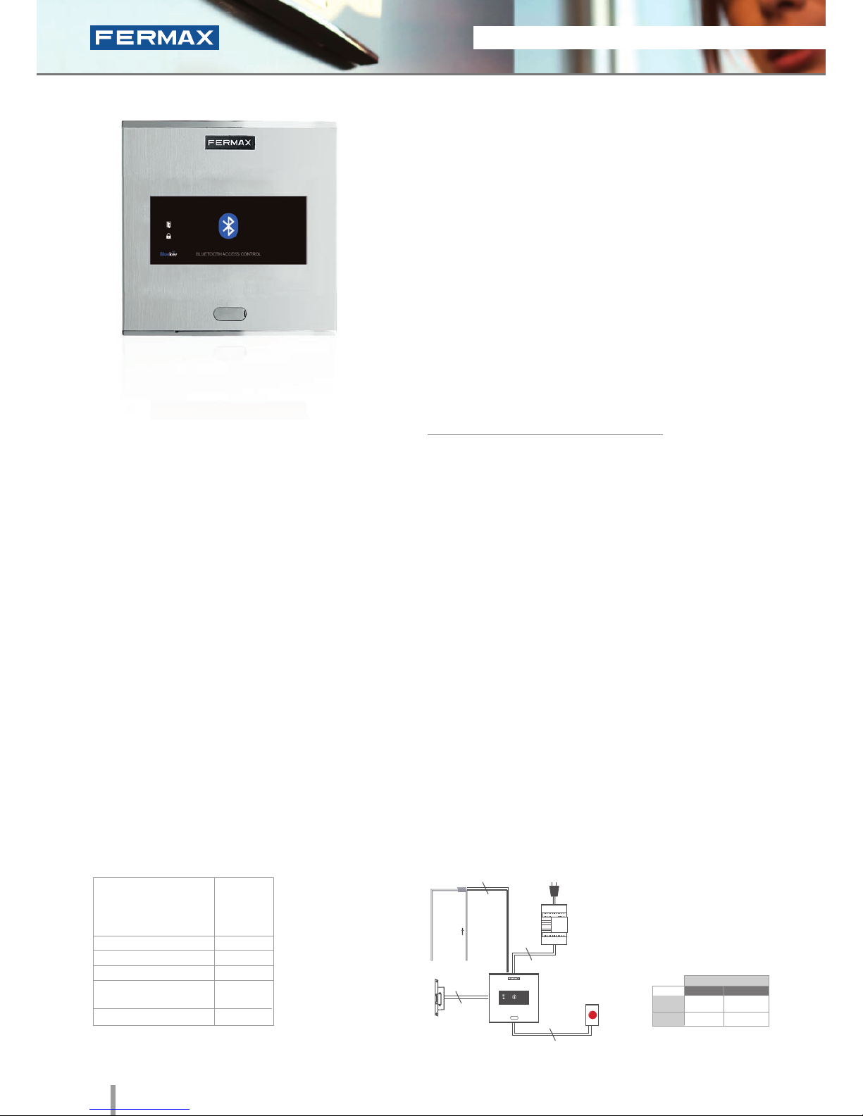
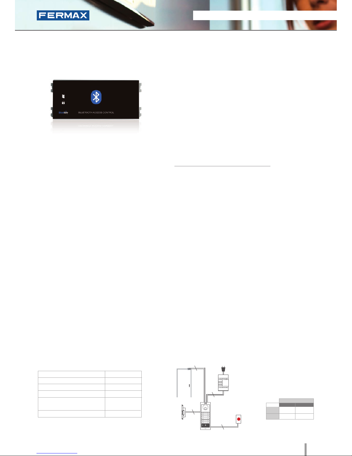
Cityline Bluetooth
Ref.6993
Bluetooth
• Access control reader which operates by means of telephones
equipped with Bluetooth technology where the mobile
telephone acts as a user identifier.
• Integrated within the Cityline aluminum panel.
• Flush mounted (ref.8948, including box) or surface installation
(ref.7061, optional).
• Recommended for interior and exterior use.
• Reader and controller integrated within the same module.
• Can operate as a stand-alone or centralised system
(congurable using dipswitch SW1).
Configuration as a STAND-ALONE system:
• Capacity based on chosen operating mode.
Operation options:
- Authorised telephones: automatic door opening or using a PIN
request and conrmation (3 modes).
Capacity: 40 mobile telephones.
- Any phone: PIN request. Capacity: Unlimited.
• Acoustic and visual confirmation using status LEDs which
confirm if a mobile phone has been accepted or rejected.
• Congurable reading range: 2m, 9m or up to 20m.
• Congurable repetition time.
PROGRAMMING
TECHNICAL FEATURES
This can be done in 2 ways: via mobile phone with bluetooth
connectivity (master mobile) using a list of commands or alternatively
via PC/PDA (with a bluetooth connection).
The «FermaxPC» programming software can be downloaded from
www.fermax.com
• Relay lock-release activation. Programmable from
01 to 99 seconds.
• Exit button input.
• Operation options:
1. Working with a list of authorised phones.
This is a list recorded on the receiver and determines
which telephones can open the door. List Capacity:
up to 40 different mobile telephones.
This working mode has three possible options:
- Automatic Mode (Without PIN): The door opens
when it detects the presence of an authorised phone.
- Request Confirmation: When the receiver detects
a phone on the list, it requests confirmation to open
the door. The user must press the 1 key and Accept
to open the door.
- Request PIN : When the receiver detects a
phone on the list it requests the PIN (4-digit code
configurable by the administrator).
2. Working without an authorised telephones list
(default conguration). The PIN will be requested for
any mobile phone with activated bluetooth within
range, and only if entered correctly the lock release
will be activated. Unlimited number of mobile phones.
Dimensions: (horizontal)x(vertical)x(depth) mm
SPECIFICATIONS
• Dimensions:
* Reader
* Flush Mounted Box
* Surface Box
• Environmental Protection (IP)
• Anti-Shock Protection (IK)
• Power Supply (V)
• Consumption (mA) S/lock rel.
• Operating Temperature
130x128
115x114x45
130x128x33
54
07
12V (ac/dc)
12Vac: 100
12Vdc 50
-15º to 55ºC
INSTALLATION
Lock-Release
Exit Button
Power
Supply
Ref.6993
230Vac
2
2
2
2
STAND-ALONE
12Vdc
12Vac
30708
3071
2888
2880
* Door lock recommended.
Normal
References
Reinforced
2011 ACCESS CONTROL 25
2011 ACCESS CONTROL 25
STAND-ALONE
12Vdc
12Vac
30708
3071
2888
2880
* Door lock recommended.
Normal
References
Reinforced
PROGRAMMING
TECHNICAL FEATURES
• Relay lock-release activation. Programmable from
01 to 99 seconds.
• Exit button input.
• Operation options:
1. Working with a list of authorised phones.
This is a list recorded on the receiver and determines
which telephones can open the door. List Capacity:
up to 40 different mobile telephones.
This working mode has three possible options:
- Automatic Mode (Without PIN): The door opens
when it detects the presence of an authorised phone.
- Request Confirmation: When the receiver detects
a phone on the list, it requests confirmation to open
the door. The user must press the 1 key and Accept to
open the door.
- Request PIN : When the receiver detects a
phone on the list it requests the PIN (4-digit code
configurable by the administrator).
2. Working without an authorised telephone list
(default conguration). The PIN will be requested for
any mobile phone with activated bluetooth within
range, and only if entered correctly the lock release will
be activated. Unlimited number of mobile phones.
This can be done in 2 ways: via mobile phone with bluetooth
connectivity (master mobile) using a list of commands or alternatively
via PC/PDA (with a bluetooth connection).
The «FermaxPC» programming software can be downloaded from
www.fermax.com
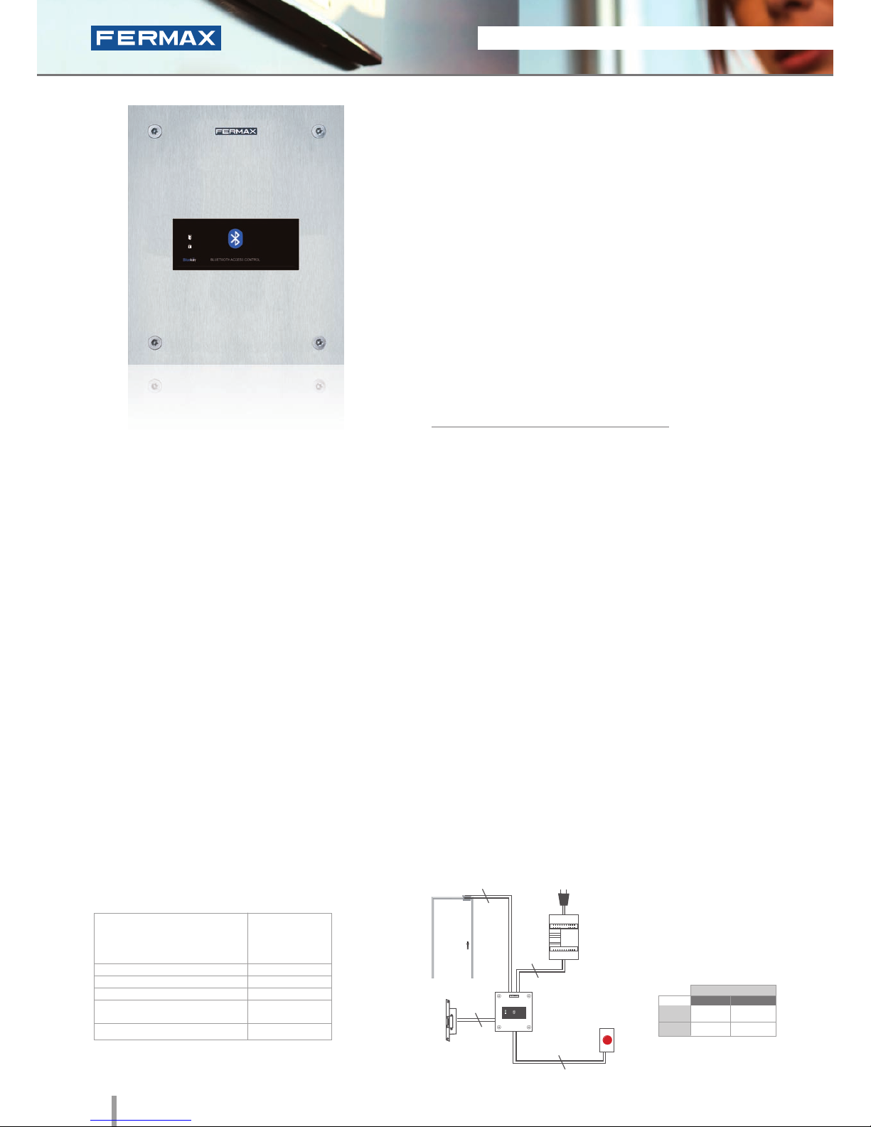
V Skyline Bluetooth
Ref.7441
Bluetooth
• Access control reader which operates by means of telephones
equipped with Bluetooth technology where the mobile
telephone acts as a user identifier.
• Access control module to be integrated within Skyline and
Cityline audio/video door entry system panels.
• Recommended for interior and exterior use.
• Reader and controller integrated within the same module.
• Can operate as a stand-alone or centralised system
(congurable using dipswitch SW1).
Configuration as a STAND-ALONE system:
• Capacity based on chosen operating mode.
Operation options:
- Authorised telephones: automatic door opening or using a PIN
request and conrmation (3 modes).
Capacity: 40 mobile phones.
- Any phone: PIN request. Capacity: Unlimited.
• Acoustic and visual confirmation using status LEDs which
confirm if a mobile phone has been accepted or rejected.
• Congurable reading range: 2m, 9m or up to 20m.
• Congurable repetition time.
The electronic or video door entry system panels are located in
the building's exterior. The panel can be configured in an intuitive
manner, including a bluetooth reader module for greater ease of
use and access security. The rest of the devices are connected to
this module and they are installed in the building's interior: power
supply and lock-release. An exit button can be used optionally.
INSTALLATION
Dimensions: (horizontal)x(vertical)x(depth) mm
SPECIFICATIONS
• Dimensions W:
• Environmental Protection (IP)
• Anti-Shock Protection (IK)
• Power Supply (V)
• Consumption (mA) S/lock-release
• Operating Temperature
105.2x47.5
54
07
12V (ac/dc)
12Vac: 100
12Vdc 50
-15º to 55º C
Lock-Release
Exit Button
Power Supply
Ref.7441
230Vac
2
2
2
2
26 2011 ACCESS CONTROL
2011 ACCESS CONTROL 27
Marine Bluetooth
Ref.5473
Bluetooth
• Access control reader which operates by means of telephones
equipped with Bluetooth technology where the mobile
telephone acts as a user identifier.
• Integrated within a 2.5mm stainless steel Marine panel.
• Flush mounted (ref.4641, including box) or surface installation
(ref.4701, optional).
• Recommended for interior and exterior use.
• Reader and controller integrated within the same module.
• Can operate as a stand-alone or centralised system
(congurable using dipswitch SW1).
Configuration as a STAND-ALONE system:
• Capacity based on chosen operating mode.
Operation options:
- Authorised telephones: automatic door opening or using a PIN
request and conrmation (3 modes).
Capacity: 40 mobile phones.
- Any phone: PIN request. Capacity: Unlimited.
• Acoustic and visual confirmation using status LEDs which
confirm if a mobile phone has been accepted or rejected.
• Congurable reading range: 2m, 9m or up to 20m.
• Congurable repetition time.
The bluetooth reader is located in the exterior area. The rest of the
devices are connected to this module and they are installed in the
building's interior: power supply and lock-release. An exit button
can be used optionally.
INSTALLATION
SPECIFICATIONS
Dimensions: (horizontal)x(vertical)x(depth) mm
• Dimensions:
* Reader
* Flush Mounted Box
* Surface box
• Environmental Protection (IP)
• Anti-Shock Protection (IK)
• Power Supply (V)
• Consumption (mA) S/lock-release
• Operating Temperature
150x180
130x160x55
154x184x55
54
09
12V (ac/dc)
12VAc: 100
12Vdc 50
-15º to 55ºC
Lock-Release
Exit
Button
Power Supply
Ref.5473
230Vac
2
2
2
2
TECHNICAL FEATURES
PROGRAMMING
This can be done in 2 ways: via a mobile phone with bluetooth
connectivity (master mobile) using a list of commands or alternatively
via a PC/PDA (with a bluetooth connection).
The «FermaxPC» programming software can be downloaded from
www.fermax.com
• Relay lock-release activation. Programmable from
01 to 99 seconds.
• Exit button input.
• Operation options:
1. Working with a list of authorised phones.
This is a list recorded on the receiver and determines
which telephones can open the door. List Capacity:
up to 40 different mobile telephones.
This working mode has three possible options:
- Automatic Mode (Without PIN): The door opens
when it detects the presence of an authorised phone.
- Request Confirmation: When the receiver detects
a phone on the list, it requests confirmation to open
the door. The user must press the 1 key and Accept to
open the door.
- Request PIN : When the receiver detects a phone
in the list it requests the PIN (4-digit code congurable
by the administrator).
2. Working without an authorised telephone list
(default conguration). The PIN will be requested for
any mobile phone with activated bluetooth within
range, and only if entered correctly the lock release will
be activated. Unlimited number of mobile phones.
STAND-ALONE
12Vdc
12Vac
30708
3071
2888
2880
* Door lock recommended.
Normal
References
Reinforced
2011 ACCESS CONTROL 27
2011 ACCESS CONTROL 27
STAND-ALONE
12Vdc
12Vac
30708
3071
2888
2880
* Door lock recommended.
Normal
References
Reinforced
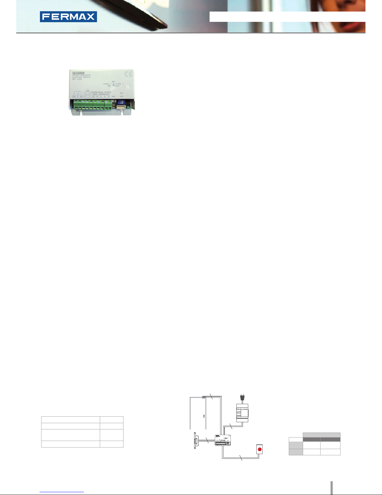
Mini Bluetooth
Ref.4479
Bluetooth
• Access control reader which operates by means of telephones
equipped with Bluetooth technology where the mobile
telephone acts as a user identifier.
• Reduced size module to be setup in the circuit box or in the
FERMAX audio/video door entry panel's flush mounted box.
• Reader and controller integrated within the same module.
• Can operate as a stand-alone or centralised system
(congurable using dipswitch SW1).
Configuration as a STAND-ALONE system:
• Capacity based on chosen operating mode.
Operation options:
- Authorised telephones: automatic door opening or
using a PIN request and conrmation (3 modes).
Capacity: 40 mobile phones.
- Any phone: PIN request. Capacity: Unlimited.
• Congurable reading range: 2m, 9m or up to 20m.
• Congurable repetition time.
PROGRAMMING
TECHNICAL FEATURES
The electronic or video door entry system panels are located
in the building's exterior. The mini-bluetooth module can be
installed internally within the flush mounted box on the panel
for greater ease of use and access security. Another option
would be to set it up internally in the circuit box. The rest of the
devices are connected to this module and they are installed in
the building's interior: power supply and lock-release. An exit
button can be used optionally.
INSTALLATION
Dimensions: (horizontal)x(vertical)x(depth) mm
SPECIFICATIONS
• Dimensions:
• Power Supply (V)
• Consumption (mA) S/lock-release
• Operating Temperature
86x60
12V (ac/dc)
12VAc: 100
12Vdc 50
-10º a 55ºC
This can be done in 2 ways: via a mobile phone with bluetooth
connectivity (master mobile) using a list of commands or
alternatively via a PC/PDA (with a bluetooth connection).
The «FermaxPC» programming software can be downloaded
from www.fermax.com
• Relay lock-release activation.
Programmable from 01 to 99 seconds.
• Exit button input.
• Operation options:
1. Working with a list of authorised phones.
This is a list recorded on the receiver and
determines which telephones can open the door.
List Capacity: up to 40 different mobile telephones.
This working mode has three possible options:
- Automatic Mode (Without PIN): The door opens
when it detects the presence of an authorised
phone.
- Request Confirmation: When the receiver detects
a phone on the list, it requests confirmation to
open the door. The user must press the 1 key and
Accept to open the door.
- Request PIN : When the receiver detects a
phone on the list it requests the PIN (4-digit code
configurable by the administrator).
2. Working without an authorised telephones list
(default conguration). The PIN will be requested for
any mobile phone with activated bluetooth within
range, and only if entered correctly the lock release
will be activated. Unlimited number of mobile phones.
Lock-Release
Power Supply
Ref.4479
230Vac
2
Exit
Button
2
2
2
28 2011 ACCESS CONTROL
2011 ACCESS CONTROL 29
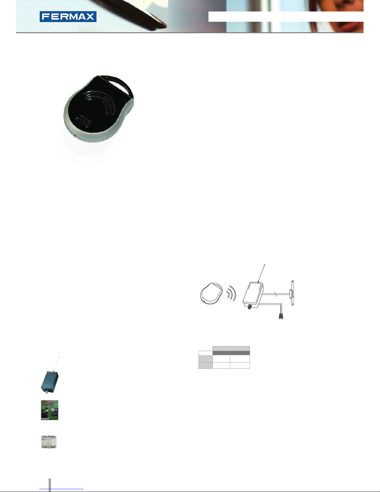
Trinary RF Dual
Channel Emitter
Ref.79561
Radio Frequency
• 433.92 MHz radio frequency emitter.
• Trinary technology
• Innovative and very robust design.
• Dual channel emitter that can activate two relays.
• Conguration of the required sequence using microswitches.
• Simplicity and ease of use.
COMPATIBLE WITH:
INSTALLATION
The reader is located in the exterior area. The rest of the
devices are connected to this module and they are installed in
the building's interior: power supply and lock-release. An exit
button can be used optionally.
TECHNICAL FEATURES
• Dip-switch conguration
(8 microswitches at 3 positions).
• Unlimited number of users permitted
by the receiver.
• Includes a 12Vdc battery
• Range: 30m.
• Frequency: 433.92 MHz.
• Consumption when transmitting: 10mA
• Standby Consumption: 0,1mA
• Dimensions: 53x63x13.
• Power supply: 12 Vc battery.
Ref.7952 mono-channel garage receiver.
Ref.7900 PCB mono-channel receiver (OEM).
Ref.7903 DIN rail mono-channel receiver.
RF Emitter
Ref.79561
Lock-Release
Receiver
2
STAND-ALONE
12Vdc
12Vac
30708
3071
2888
2880
* Door lock recommended.
Normal
References
Reinforced
 Loading...