

Fermax KITS VIDEO VDS NCITY 1-2-3L Installer Manual
ESPAÑOL
ENGLISH
FRANÇAIS
DEUTSCH
PORTUGUÊS
KITS VIDEO VDS NCITY 1-2-3L
1-2-3L VDS NCITY VIDEO KITS
KITS VIDÉO VDS NCITY 1-2-3L
VIDEO-SETS VDS NCITY 1-2-3L
KITS VÍDEO VDS NCITY 1-2-3L
MANUAL DE INSTALADOR Y USUARIO
USER& INSTALLER’S MANUAL
MANUEL D´INSTALLATION ET UTILISATION
INSTALLATIONS-und BENUTZERHANDBUCH
MANUAL DO INSTALADOR E USUÁRIO

Pag 2
Kit Video VDSKit Video VDS
Kit Video VDSKit Video VDS
Kit Video VDS
Kit Video VDSKit Video VDS
Kit Video VDSKit Video VDS
Kit Video VDS
Cod. 97483b V01_10
«KIT VIDEO LOFT VDS»
«LOFT VDS VIDEO KIT MANUAL»
«MANUEL DU KIT LOFT VDS»
«HANDBUCH DIGITAL VIDEO-SET»
«MANUAL KIT VIDEO LOFT VDS»
- Kit 1 Línea - Kit 1 Way - Kit 1 Ligne - Einfamilienhaus-Set - Kit 1 Linha
- Kit 2 Líneas - Kit 2 Ways - Kit 2 Lignes - Zweifamilienhaus-Set - Kit 2 Linhas
- Kit 3 Líneas - Kit 3 Ways - Kit 3 Lignes - Dreifamilienhaus-Set - Kit 3 Linhas
(B/N y Color - W/B & Colour - N/B et Couleur - S/W und Farbe - P/B e Cor)
E
EN
F
D
P

Pag 3
Kit Video VDSKit Video VDS
Kit Video VDSKit Video VDS
Kit Video VDS
Kit Video VDSKit Video VDS
Kit Video VDSKit Video VDS
Kit Video VDS
ENHORABUENA POR DISPONER DE UN PRODUCTO DE CALIDAD!
Fermax electrónica desarrolla y fabrica equipos de prestigio que cumplen los más
altos estándares de diseño y tecnología.
Su monitor de videoportero FERMAX le permitirá comunicarse con la placa de calle,
ver la persona que le está llamando y abrirle la puerta de entrada si así lo desea.
Esperamos disfrute de sus funcionalidades.
www.fermax.com
E
EN
F
D
CONGRATULATIONS ON PURCHASING THIS QUALITY PRODUCT!
Fermax Electronics develops and manufactures reputable equipment which fulfils
the highest design and technology standards.
Your FERMAX video door entry system allows you to communicate with the entry
panel, to see who is calling and to open the door if you wish.
We hope you enjoy its range of functions.
www.fermax.com
FÉLICITATIONS ! VOUS VENEZ D’ACQUÉRIR UN VÉRITABLE PRODUIT DE QUALITÉ!
Fermax Electrónica développe et fabrique des équipements de prestige qui répondent
aux normes de design et technologie les plus développées.
Votre moniteur pour portier vidéo FERMAX vous permettra de communiquer avec la
platine de rue, de voir la personne qui vous appelle et d’ouvrir la porte d’entrée si
vous le souhaitez.
Nous espérons que vous profiterez pleinement de toutes ses fonctions.
www.fermax.com
WIR GRATULIEREN IHNEN ZUM KAUF DIESES QUALITÄTSPRODUKTS!
Fermax Electrónica entwickelt und fabriziert hochwertige Anlagen, die den höchsten
Technologie- und Designstandards entsprechen.
Der Monitor der Videotürsprechanlage von FERMAX ermöglicht Ihnen eine
Sprechverbindung mit der Türstation herzustellen, die Person, mit der Sie sprechen
auf dem Bildschirm zu betrachten und bei Bedarf die Tür zu öffnen.
Überzeugende Funktionalität für Ihr Eigenheim!
www.fermax.com
P
PARABÉNS POR DISPOR DE UM PRODUTO DE QUALIDADE!
Fermax electrónica desenvolve e fabrica equipas de prestígio que cumprem com
os mais altos estándars de desenho e tecnologia.
O seu monitor de vídeo-porteiro FERMAX lhe permitirá comunicar-se com a placa
da rua, ver a pessoa que lhe está a chamar e abrir-lhe a porta de entrada se assim
o deseja.
Esperamos que aproveites as suas funcionalidades.
www.fermax.com

Pag 4
Kit Video VDSKit Video VDS
Kit Video VDSKit Video VDS
Kit Video VDS
Kit Video VDSKit Video VDS
Kit Video VDSKit Video VDS
Kit Video VDS

Pag 5
Kit Video VDSKit Video VDS
Kit Video VDSKit Video VDS
Kit Video VDS
Kit Video VDSKit Video VDS
Kit Video VDSKit Video VDS
Kit Video VDS
E
EN
F
INDICE - INDEX - SOMMAIRE
SECTION I - INSTALLER MANUAL ............................................................................. 7
Power Supply installation ............................................................................... 8
Outdoor Panel installation .............................................................................. 8
Panel adjustment ............................................................................................ 9
Monitor Installation .......................................................................................... 14
Monitor programming ...................................................................................... 14
Call tone selection........................................................................................... 15
Wiring diagrams .............................................................................................. 16
Technical Features .......................................................................................... 28
Events and solutions table ............................................................................. 31
SECTION II - USER MANUAL ...................................................................................... 35
Controls ............................................................................................................ 36
Operation .......................................................................................................... 37
SECTION I - MANUEL D’INSTALLATION .................................................................... 7
Installation de l’alimentation .......................................................................... 8
Installation de la platine de rue ..................................................................... 8
Reglages de la platine.................................................................................... 9
Installation du moniteur .................................................................................. 14
Programmation du moniteur .......................................................................... 14
Sélection de la tonalité d’appel...................................................................... 15
Schéma de câblage ........................................................................................ 16
Caracteristiques Techniques ......................................................................... 28
Tableau de depannage ................................................................................... 32
SECTION II - MANUEL D’UTILISATION ...................................................................... 35
Controles .......................................................................................................... 36
Fonctionnement ............................................................................................... 37
SECCION I - MANUAL DEL INSTALADOR .................................................................. 7
Instalación del Alimentador ............................................................................ 8
Instalación de la placa de calle ..................................................................... 8
Ajustes finales de placa ................................................................................. 9
Instalación del monitor ................................................................................... 14
Programación del monitor.............................................................................. 14
Selección del tono de llamada ...................................................................... 15
Esquemas de cableado.................................................................................. 16
Características Técnicas ................................................................................ 28
Tabla de incidencias y soluciones ................................................................ 30
SECCION II - MANUAL DE USUARIO ......................................................................... 35
Controles .......................................................................................................... 36
Funcionamiento ............................................................................................... 37

Pag 6
Kit Video VDSKit Video VDS
Kit Video VDSKit Video VDS
Kit Video VDS
Kit Video VDSKit Video VDS
Kit Video VDSKit Video VDS
Kit Video VDS
INHALT - INDICE
SECÇÃO I - MANUAL DO INSTALADOR .................................................................... 7
Instalação do transformador .......................................................................... 8
Instalação da Placa de Rua ........................................................................... 8
Ajustes da placa .............................................................................................. 9
Instalação do Monitor ...................................................................................... 14
Programação Monitor. ..................................................................................... 14
Selecção do som de chamada ...................................................................... 15
Esquemas cablagem...................................................................................... 16
Características Técnicas ................................................................................ 28
Tabela de incidências e soluções ................................................................. 34
SECÇÃO II - MANUAL DO UTILIZADOR ..................................................................... 35
Comandos........................................................................................................ 36
Funcionamento ................................................................................................ 37
TEIL I – INSTALLATIONSANLEITUNG ........................................................................ 7
Installation des Netzgeräts ............................................................................ 8
Installation der Türstation .............................................................................. 8
Konfiguration und Einstellungen der Türstation .......................................... 9
Befestigung des Monitors............................................................................... 14
Programmierung des Monitors ...................................................................... 14
Auswahl des Ruftons ...................................................................................... 15
Verkabelungsschema ..................................................................................... 16
Technische Eigenschaften ............................................................................. 28
Ereignistabelle und Lösungen ...................................................................... 33
TEIL II - BEDIENUNGSANLEITUNG ............................................................................. 35
Bedienung ........................................................................................................ 36
Funktionselemente.......................................................................................... 37
D
P

Pag 7
Kit Video VDSKit Video VDS
Kit Video VDSKit Video VDS
Kit Video VDS
Kit Video VDSKit Video VDS
Kit Video VDSKit Video VDS
Kit Video VDS
Sección I - Manual del Instalador
Section I - Installer Manual
Section I - Manuel d’installation
Teil I - Installationsanleitung
Secção I - Manual do instalador
E
EN
F
D
P
Pag 8
Kit Video VDSKit Video VDS
Kit Video VDSKit Video VDS
Kit Video VDS
Kit Video VDSKit Video VDS
Kit Video VDSKit Video VDS
Kit Video VDS
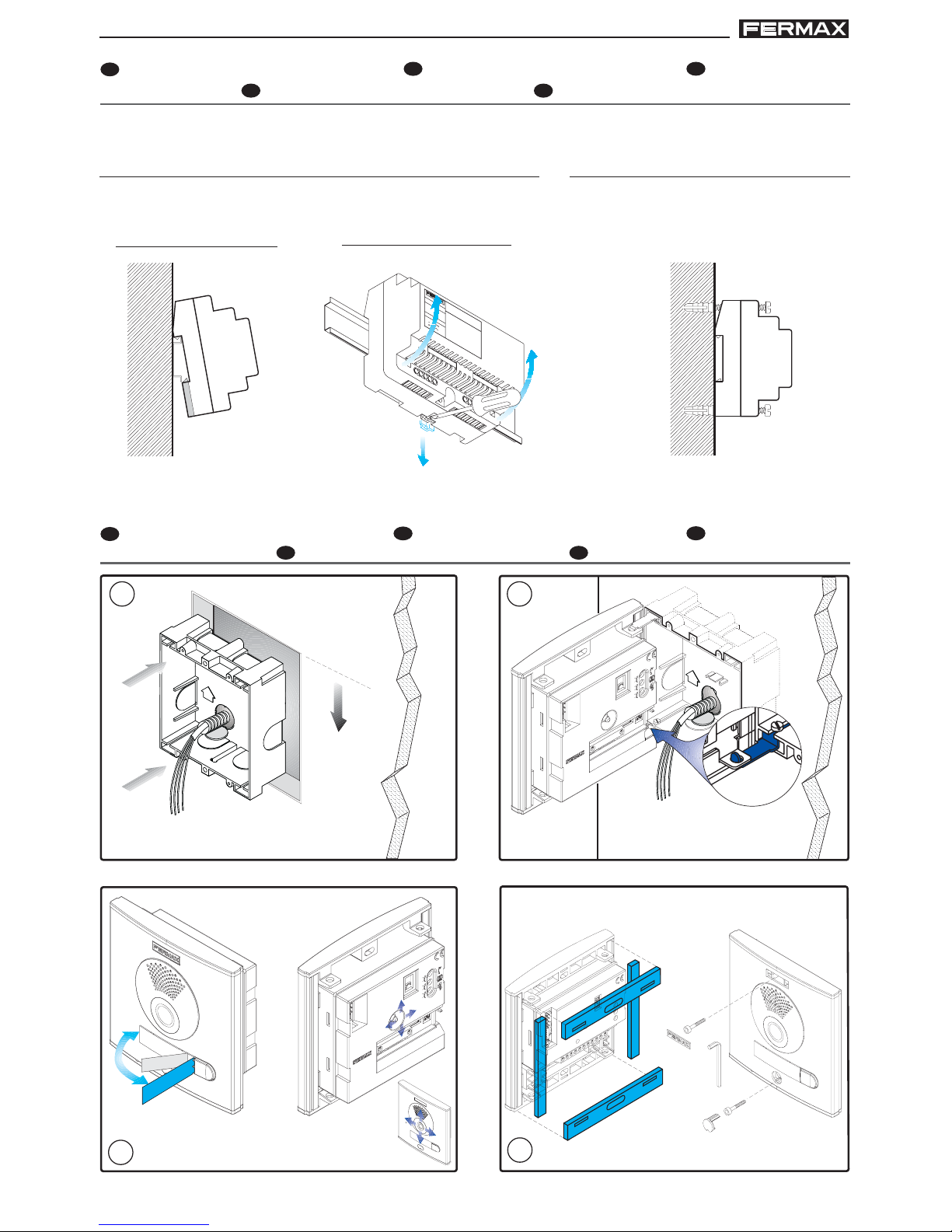
Desmontaje - Disassembly
Démontage - Ansbau
Desmontagem
Instalación en carril DIN - DIN rail Installation
Installation sur rail DIN - DIN-Schiene Installation
Instalação em carril DIN
Montaje - Assembly
Montage - Einbau
Montagem
Fijación con tornillos - Fixing with screws
Fixation au moyen de vis - Befestigung
mit Schrauben - Fixação com parafusos
+
1
8
V
1
.
5
A
5
0
6
0
H
z
.
5
0
V
A
M
A
X
.
1
2
V
1
A
F
U
E
N
T
E
A
L
IM
E
N
T
A
C
IO
N
K
IT
D
IG
IT
A
L
M
A
D
E
I
N
S
P
A
I
N
E
INSTALACIÓN DEL ALIMENTADOR EN POWER SUPPLY INSTALLATION
F
INSTALLATION DE
L’ALIMENTATION D INSTALLATION DES NETZGERÄTS P INSTALAÇÃO DO TRANSFORMADOR
E
INSTALACIÓN PLACA DE CALLE
EN
OUTDOOR PANEL INSTALLATION
F
INSTALLATION DE
LA PLATINE DE RUE
D
INSTALLATION DER TÜRSTATION
P
INSTALAÇÃO DA PLACA DE RUA
1.70m
5.57 feet
M
A
R
IA
LORCA
4
3
1 2
Pag 9
Kit Video VDSKit Video VDS
Kit Video VDSKit Video VDS
Kit Video VDS
Kit Video VDSKit Video VDS
Kit Video VDSKit Video VDS
Kit Video VDS
(*) Configuración por defecto: Placa Principal - Default Configuration: Main Panel - Configuration par défaut :
platine principale - Standardkonfiguration: Haupttürstation - Configuração por defeito: Placa Principal
E
EN
F
D
P
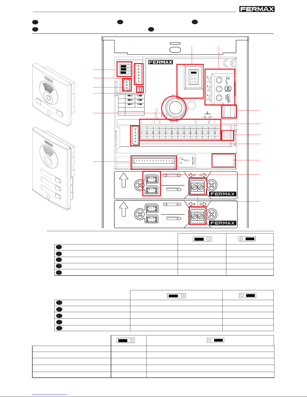
Leds cámara
Camera LEDs
DEL de la caméra
Leuchtdioden der Kamera
Leds de câmara
JP3
apagados siempre
always off
toujours éteintes
immer ausgeschaltet
sempre apagados
encendidos cuando la camara está activada
ON when the camera is active
ON quand la caméra est activée
ON wenn die Kamera aktiv ist
ON quando a câmara está activada.
Placa Principal
Main Panel
Platine principale
Haupttürstation
Placa Principal
Placa Secundaria
Secondary Panel
Platine secondaire
Nebentürstation
Placa Secundária
(*)
E
EN
F
D
P
JP2
Selección Placa Principal / Placa Secundaria
Main Panel/Secondary Panel Selection
Sélection de la platine principale / platine secondaire
Auswahl Haupttürstation / Nebentürstation
Selecção de Placa Principal / Placa Secundária
E
AJUSTES DE LA PLACA EN PANEL ADJUSTMENT F RÉGLAGES DE LA PLATINE
D
EINSTELLUNGEN DER TÜRSTATION P AJUSTES DA PLACA
ARRIBA
UP
CP
+
-
ARRIBA
UP
CP
+
-
AMPLIFICADOR ADS/VDS
ADS/VDS AMPLIFIER
AMPLIFICATEUR ADS/VDS
ADS/VDS VERSTÄRKER
MIC
EXITEXIT
JP3
JP2
PACK EXTENSION
CN1
CN2
LEDS ON
SLAVE
MASTER
LEDS OFF
TARJETERO
CARD HOLDER
AUDIO
PROG
C
NO
NC
VERSION :
LANGUAGE
IDIOMA
10
PAN & TILT
D
C
B
A
JP3 JP2
CN3
SW1
CN1
CN2
MIC
JP4
JP4
CT OUT CT IN
L
+
-
M
V
+12
C
NcNo
-
BS
S
CT
18V
DC
ALIMENTACION
POWER SUPPLY
18 Vdc
-+
CN7 VIDEO TEST MONITOR
A)
B)
C)
E) F)
G)
H)
I )
D)
J )
K )
L )
M)
A)
N)
O)
CT: Activación cámara/salida auxiliar
CT: Camera activation/auxiliary output
CT : Activation caméra / sortie auxiliaire
CT: Kameraaktivierung/Nebenausgang
CT: Activação da câmara/saída auxiliar
CT: salida 11 Vdc
CT: 11 Vdc output
CT : sortie11 Vcc
CT: 11 VDC Ausgang
CT: saída de 11 VDC
JP4
CT: entrada. Conectar 12 Vdc para activar permanentemente cámara+ leds
CT: input:. Connect 12 Vdc to permanently activate camera + LEDs
CT : entrée. Connecter 12 Vcc pour activer en permanence caméra + leds
CT: Eingang. 12 VDC NG anschließen um Kamera und LEDs permanent zu aktivieren
CT: entrada. Ligar 12 VDC para activar permanentemente a câmara+ LEDS
Pag 10
Kit Video VDSKit Video VDS
Kit Video VDSKit Video VDS
Kit Video VDS
Kit Video VDSKit Video VDS
Kit Video VDSKit Video VDS
Kit Video VDS
B)
E
EN
F
D
P
CN1
Conexión Módulo de extensión de llamadas o hasta 3 pulsadores
Call extension or up to 3 pushbuttons
Conexion module d’extension d’appels ou jusqu'à 3 boutons-poussoirs
Anschluss Anruferweiterungsmodul oder bis zu 3 Tasten
Ligação do Módulo de extensão de chamadas ou até 3 botões
D
P
Común de pulsadores
Common Button Wire
Connecteur commun de
boutons-poussoirs
Gemeinsamer Draht der Klingeltasten
Comum de botões
CN2
Luz tarjetero pulsador
Cardholder Backlight
Lumière porte-étiquettes
bouton-poussoir
Beleuchtung Taste Infomodul
Luz do porta-cartões do botão
Conexión Pulsadores
Button Connection
Connexion
boutons-poussoirs
Anschluss Tasten
Ligação dos Botões
C)
L+ / L- CP
E
EN
F
D)
E
EN
F
D
P
DL2
Si existe un cortocircuito entre + y L, al llamar desde placa emite una serie de destellos cortos
If there is a short circuit between + and l, when a call is made from the panel, it emits a series of short flashes
S'il existe un court-circuit entre + e L lors d’un appel de la platine, elle émet una série de brefs clignotements
Falls ein Kurzschluss zwischen + und L bei der Durchführung eines Anrufs, blinkt diese mehrmals kurz auf
Se existir um curto-circuito entre + e L, ao realizar uma chamada a partir da placa emite luz intermitente rápida
Led Diagnóstico
Diagnostic Led
Diagnostic Del
Diagnose-LED
Led diagnóstico
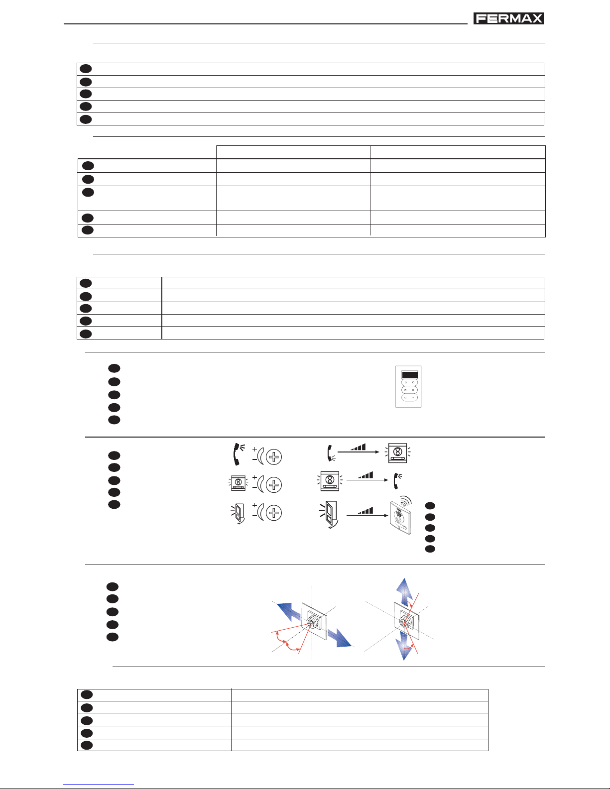
10º
10º
10º
10º
G)
E
Enfoque la telecámara
EN
Focus the camera
F
Réglez la caméra vidéo
D
Richten Sie die Kamera aus
P
Focar a telecâmara.
Pan&Tilt (±10º)
E
Ajuste audio
EN
Adjust the audio
F
Réglez le volume
D
Audioeinstellung
P
Ajuste o áudio
F)
E
“puerta abierta”
EN
“open door”
F
« porte ouverte »
D
“Tür offen”
P
“porta aberta”
A
B
C
D
IDIOMA
LANGUAG
E
E)
E
Selección del idioma del mensaje de «puerta abierta».
EN
Select language for «open door» message.
F
Sélection de la langue du message « porte ouverte ».
D
Sprachwahl der Meldung «Tür offen».
P
Selecção da língua da mensagem de «porta aberta».
A: Español
B: Français
C. English
D: Deutsch
CN7
H)
E
EN
F
D
P
Conector de test y progarmación de monitores
Test and monitor programming connector
Connecteur de test et programmation d’écrans
Testanschluss und Monitorprogrammierung
Conector de teste e programação de monitores
Video Test monitor
Video test monitor
Écran de Test Vidéo
Video Testmonitor
Video Test monitor

Pag 11
Kit Video VDSKit Video VDS
Kit Video VDSKit Video VDS
Kit Video VDS
Kit Video VDSKit Video VDS
Kit Video VDSKit Video VDS
Kit Video VDS
D
Anschlüsse Türstation:
• Video-Klemmen (Koaxial)
V: Kern
M: Schirm
Ct: Aktivierung der Kamera (10 VDC)
• Anschlussklemmen des Systems:
+, - : Stromversorgung (18 VDC)
L: Daten-Bus
+12: 12 V Gleichstrom (0,5A)
C, NA, NC: Relais-Kontakte (4A)
(Verbindung Türöffner)
BS, -: Drucktaste Flur
S: Aktivierung des Umschalters.
P
Conectores de Placa:
• Terminais de vídeo (coaxial).
V: vivo
M: malha
Ct: activação telecâmara (10 Vdc)
• Terminais de ligação do sistema:
+, - : alimentação (18 Vdc).
L: bus de dados.
+12: 12 Vdc (0,5A)
C, NA, NC: contactos de relé (4A)
(ligação do trinco)
SP, - : sensor de porta aberta.
S: activação do comutador
F
Connecteurs platine:
• Bornes vidéo (câble coaxial).
V : vif
M : maille
Ct : activation caméra (10 Vdc)
• Bornes de raccordement du système.
+, - : alimentation (18 Vcc).
L : bus de données.
+12: 12 Vcc (0,5A)
C, NA, Nc: contacts relais (4A)
(connexion gâche électrique)
BS, - : bouton-poussoir vestibule.
S : activation de l’échangeur.
J)
EN
Panel Connectors:
• Video terminals (coaxial):
V: live
M: shield
Ct: camera activation (10 Vdc)
• System connection terminals:
+, -: power supply (18 Vdc).
+12: 12 Vdc output.(0,5A)
L: data bus.
C, NA, NC: relay contacts (4A)
(door-opener connection)
BS, -: entrance hall button.
S: activation of the exchanger
E
Conectores Placa:
• Bornas de video, (coaxial).
V: vivo
M: malla
Ct: activación telecamara (10 Vdc)
• Bornas de Conexión del sistema:
+, -: alimentación (18 Vdc).
L: bus de datos.
+12: salida12 Vdc (0,5A)
C, NA, NC: contactos relé (4A)
(conexión abrepuertas)
BS, -: pulsador zaguán.
S: activación del cambiador
I)
MIC
Conexión micrófono (micrófono ubicado en el perfil inferior de la placa)
Microphone connection (microphone located in the lower panel profile)
Connexion microphone (microphone placé sur le profil inférieur de la platine)
Mikrofonanschluss (Mikrofon befindet sich am unteren Profil der Türstation)
Ligação do microfone (microfone localizado no perfil inferior da placa)
E
EN
F
D
P
K)
E
EN
F
D
P
SW1
Mapeado: botón para entrar en modo programación de pulsadores. Ver manual “Mapeado”
Mapping: button to enter button programming mode. See manual ‘Mapping’
Mappage: bouton pour entrer en mode programmation de boutons-poussoirs. Voir manuel « Mappage»
Mapping: Programmiertaste der Klingeltasten Siehe Handbuch“Mapping”
Mapeamento: botão para aceder ao modo de programação de botões. Ver o manual “Mapeamento”
Pag 12
Kit Video VDSKit Video VDS
Kit Video VDSKit Video VDS
Kit Video VDS
Kit Video VDSKit Video VDS
Kit Video VDSKit Video VDS
Kit Video VDS
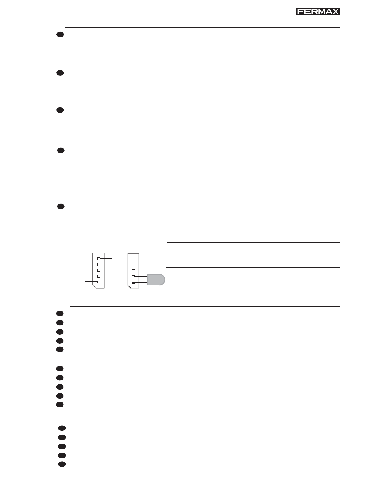
L)
E
CN3: Conexión leds de estado. De gran utilidad para personas discapacitadas,
permite conectar leds que informan del estado de la comunicación.
L2, L3, L4: entregan un negativo cuando se realiza la acción correspondiente,
activando el led conectado entre “Lx” y “+”:
EN
CN3: Connection Status Leds Very useful for disabled people, allowing leds to be
connected which provide information on communication status.
L2, L3, L4: generates a negative signal when the corresponding action is taken,
activating the led connected between “Lx” and “+”:
F
CN3 : connexion DEL d’état. Très utile pour les personnes handicapées, il permet
de raccorder des DEL indiquant l’état de la communication.
L2, L3, L4 : transmettent un négatif lorsque l’action correspondante est effectuée,
en activant la DEL raccordée entre « Lx » et « + ».
D
CN3: Anschluss LED-Statusanzeige Von großem Nutzen für behinderte Personen;
ermöglicht das Anschließen von LEDs, die über den Zustand der Verbindung
informieren.
L2, L3, L4: übermitteln einen Negativstrom, wenn der entsprechende Vorgang
ausgelöst wird, worauf die angeschlossene LED zwischen “Lx” und “+” aktiviert
wird:
P
CN3: Ligação dos LEDS de estado. De grande utilidade para pessoas deficientes,
permite deficientes que informam do estado da comunicação.
L2, L3, L4: entregam um negativo quando se realiza a acção correspondente,
activando o led ligado entre «Lx» y «+»:
Led de llamada
Call Led
DEL d’appel
LED Anruf
LED de chamada
Led di chiamata
L2
Led de comunicación
Communication Led
DEL de communication
LED Sprechverbindung
LED de comunicacão
Led di comunicazione
Led apertura de puerta
Lock Release Led
DEL ouverture des portes
LED Türöffnung
LED abertura de porta
Led di apertura porta
L3 L4
L4
+
L1
L2
L3
L4
E
Versión del amplificador
EN
Amplifier version
F
Version de l’amplificateur
D
Lautsprecherversion
P
Versão do amplificador
M)
E
Conexión al amplificador (C) o módulo de pulsador anterior/posterior
EN
Connection to amplifier (C) or previous/subsequent button module
F
Connexion à l’amplificateur (C) ou au module du bouton-poussoir précédent/suivant
D
Anschluss an Verstärker (C) oder voriges/nachfolgendes Tastenmodul
P
Ligação ao amplificador (C) ou ao módulo de botão anterior/posterior
N)
E
Conexión entre pulsador y Módulo de extensión de llamadas
EN
Connection between the button and call extension module
F
Connexion entre le bouton-poussoir et le module d’extension des appels
D
Anschluss zwischen Taste und Anruferweiterungsmodul
P
Ligação entre o botão e o Módulo de extensão de chamadas
O)
 Loading...