

Fermax IP-Fermax IPF-00, IP-Fermax IPF-01, IP-Fermax IPF-00C, IP-Fermax IPF-02, IP-Fermax IPF-01C Installation And Operating Instructions Manual
...Page 1
IP-Fermax
IPF-00, IPF-01, IPF-02
IPF-00C, IPF-01C, IPF-02C
Installation and operating instructions
IP-Fermax - DoorPhone
Page 2

Welcome
Congratulation to purchase modern VOIP door entry system “VoIP Door
Phone Fermax” IP Fermax. This door entry widely satisfy your needs for
communication to visitors of your company, homes, schools etc…
Simply VoIP means “Voice over Internet Protocol” – this door entry is
connectable to IP network and allows 2 ways of calling. Either P2P (peer to peer)
– it means call directly to IP adress of other VOIP device or registrates to SIP
server ( as SIP client) and then call phone number.
To each button you can assign 5 phone numbers with possibility of progressive
or simoultaneous dial.
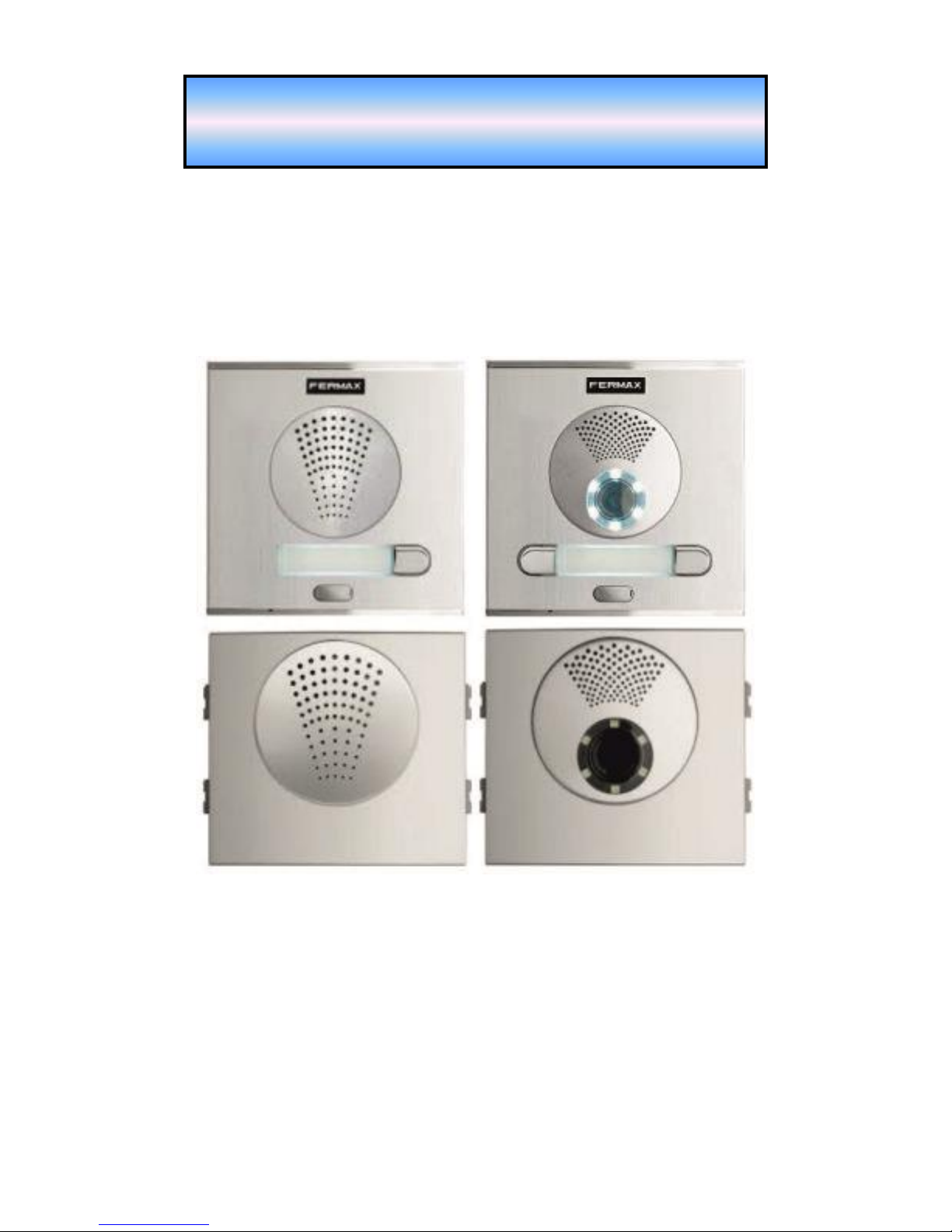
The IP-Fermax doorphone comes with one or two buttons or no push-button,
either with color camera or without camera. The system is modular and can be
expanded to up to 200 buttons and equipped with a keypad.
The IP-Fermax doorphone is powered by a 12V power supply that can be used
to power the door lock or the IP-Fermax can be PoE powered (Power over
Ethernet). The features are similar to a hand-free phone. Basic features include
the ability to open up to 2 doors with connected electrical locks and easy
programming via the WEB interface.
Manual version V3.5 5-9-2016
Valid for firmware – V3.4.xx
Alphatech Technologies s.r.o.
Jeremenkova 88
140 00 Praha 4, CZ
www.alphatechtechnologies.cz
support@alphatechtechnologies.cz
Producer progressively improves features of the unit (firmware). The door
entry IP Fermax allows whenever upgrade the firmware by newest version via
PC. Latest firmware version you can download from
www.alphatechtechnologies.cz .
Neccessary guides you find at page 69. We recommend always use latest
firmware version which brings new features as same as eventual correction of
errors of previous versions. At www.alphatechtechnologies.cz you can also
find latest versions of user documentation.
Page 3
IP VarioBell - installation and operating instructions
3
Contents
BASIC DESCRIPTION ....................................................................................... 5
FEATURES ...................................................................................................... 5
USED TERMINOLOGY ...................................................................................... 6
ASSEMBLY OF MODULES ................................................................................ 8
Voice modules without a camera .............................................................. 8
Voice modules with a camera ................................................................... 9
Push button modules and keypad ............................................................ 10
Numeric keypad ...................................................................................... 10
Mechanical parts .................................................................................... 11
MOUNTING OF IP FERMAX ........................................................................... 12
Mounting on the wall .............................................................................. 12
Mounting into the wall ............................................................................ 12
CONNECTION OF IP-FERMAX ....................................................................... 13
IP-Fermax main board .......................................................................... 13
Front panel ............................................................................................. 16
Camera (22) ............................................................................................ 17
Replacement of name cards .................................................................... 17
Power supply - clamp (10) ...................................................................... 18
Micro SD card (4) ................................................................................... 18
CONNECTION OF SWITCHES .......................................................................... 19
PoE power supply source ........................................................................ 21
Code relay (COSW) ................................................................................ 22
Use of door sensors – exit button ............................................................ 22
NUMBERING OF PUSH BUTTONS ................................................................ .... 23
SERVICE OF IP-FERMAX ............................................................................. 24
SIGNALLING OVERVIEW ............................................................................... 24
OVERVIEW OF SIGNALLING .......................................................................... 24
VISITOR AT DOOR ......................................................................................... 24
Push Button press – outgoing call .......................................................... 24
Button press – code lock ......................................................................... 25
Call ......................................................................................................... 25
VISITOR INSIDE BUILDING ............................................................................ 26
Outgoing call .......................................................................................... 26
Incoming call .......................................................................................... 26
VIDEO .......................................................................................................... 27
PARAMETRES PROGRAMMING ................................................................ 28
WEB INTERFACE ACCESS ............................................................................. 28
What you should know ............................................................................ 28
Login ................................ ................................ ................................ ....... 29
CURRENT STATUS ........................................................................................ 30
Page 4

IP VarioBell - installation and operating instructions
4
Language settings ................................................................................... 31
IP NETWORK SETTING .................................................................................. 31
IP Network setting .................................................................................. 31
SIP setting ................................................................ ............................... 34
WEB server ............................................................................................. 38
BASIC SETTING ............................................................................................. 40
Phone book ............................................................................................. 40
Relays ...................................................................................................... 43
Door sensors ........................................................................................... 47
Setting SNMP .......................................................................................... 48
Time profiles ........................................................................................... 49
Date and time setting .............................................................................. 50
E-mail ..................................................................................................... 52
EXTENDED SETTING ................................................................ ..................... 54
DoorPhone .............................................................................................. 54
Audio setting ........................................................................................... 57
Audio codecs ........................................................................................... 58
Video setting ........................................................................................... 59
Video watching (PopUp programm) ....................................................... 60
Video codecs ........................................................................................... 61
Streaming ................................................................................................ 62
SERVICE ....................................................................................................... 64
Restart ..................................................................................................... 64
Configuration .......................................................................................... 65
Language and style ................................................................................. 66
Style and language preparation .............................................................. 67
Firmware upgrade .................................................................................. 69
Logfile ..................................................................................................... 70
License .................................................................................................... 72
Sound files ............................................................................................... 73
TECHNICAL PARAMETRES......................................................................... 74
ELECTRICAL PARAMETRES ........................................................................... 74
MECHANICAL DIMENSIONS .......................................................................... 74
VIDEO PARAMETRES .................................................................................... 75
Requests .................................................................................................. 76
Page 5

IP VarioBell - installation and operating instructions
5
Basic description
Features
▪ audio is full duplex with ECHO cancellation
▪ phone book for 999 subscribers with 5 tel. numbers for each (max. 200
physicaly buttons + keyboard)
▪ every subscriber has more phone numbers with progressive or simultaneous
calling
▪ Email sending when is unreachable including attachment with pictures
▪ 10 time plans with week programm
▪ 4 relays. 2 included on board with possibility connect 2 independent locks for
door opening and 2 virtual (webrelays) (for remote control of IP relay or relays
synchronization)
▪ Relays system via synchronization allows combination of any mode
(progressive opening, 2 pulses etc..)
▪ 10 shared adjustable codes for every relay + every subscriber has own code
for every relay
▪ all versions can use door sensors or exit buttons
▪ SNMP usage possibility
▪ real time clocks from NTP or SIP server
▪ extendable possibilities of buttons functionality, light intensity settings, call
duration restriction, etc...
▪ audio signalling settings, saving own tones or messages
▪ multilanguage support
▪ multilevel loading and configuration refresh
▪ relaible firmware upgrade
▪ loging system with possibility of data saving to MicroSD card (we prepare)
▪ picturesas same as video saving possibility to MicroSD card (we prepare)
▪ WEB inerface management
▪ power supply 12V or PoE (Class 0 - 12,95W)
▪ Ethernet – 10/100Mb with standard 10BaseT and 100BaseTx
▪ unit start within 10 seconds
▪ Linux operating system
▪ USB connection of integrated webcamera. Video transmission to webbrowser
- JPEG, video transmission to VoIP phones - stream H.263, H.264
▪ SIP connection P2P or PBX (SIP server) system,switchable in web interface
▪ SIP 2.0 protocol , define RFC3261
Page 6

IP VarioBell - installation and operating instructions
6
Used terminology
• Incoming call - Connection between a Brave and a phone made by selecting
an option on the phone. The Brave connects the call after set number of rings.
The Brave can be programmed from the phone following a connection by
inputting a password.
• Outgoing call - Connection between the Brave and a phone made by choosing
an option on the Brave (i.e. Pressing a button).
• External code - Combination of 10 buttons or keyboard keys (after pressing the
B symbol or bell symbol) for a relay activation. [External = enter code outside
the building]
• Internal code - Combination of 10 buttons on phone for a relay activation (by
DTMF). [Internal = enter code inside the building].
• Code lock - Function for relay connections by inputting a combination of up to
10 buttons or keyboard keys (after pressing the key symbol)
• Ethernet is technology which is used to build up local networks (LAN)
• LAN - Local Area Network (local network) mark PC network which cover small
geographical area (for example homes, office, etc…).
• 10Base-T As transmission medium use twisted twoline cable with rate
10 Mbit/s. It used 2pairs of structured cabling from four.
• 100Base-TX Version with transmission rate 100 Mbit/s, which is named Fast
Ethernet. It used 2 pairs UTP or STP cable category 5.
• Twisted 2line or also twisted pair is cable type which is used in PC
networks. Twisted 2line is created by cables pair which are regularly twisted in
the length and after pairs are twisted together.
• UTP, Unshielded Twisted Pair
• STP, Shielded Twisted Pair
• WEB - World Wide Web (WWW, shortly web), is mark for application of http
internet protocol
• HTTP (Hypertext Transfer Protocol) is internet protocol design for exchange of
hypertex documents in format HTML
• USB (Universal Serial Bus) . Modern way of accessories connection to PC
• Video codec (compound of word begins „coder and decoder“) . Compression
H.263 is derived from MPEG-4, H.264 is coder for format MPEG-4 AVC.
MPEG-4 is kind of video compression – decreasement of pictures sequence
data flow
• JPEG is standard method of loss making compression used for savings PC
pictures
• Voice over Internet Protocol (shortly VoIP) is technology allows transmission
of digitized voice in body of family protocols UDP/TCP/IP pockets via PC
network . It is used for calling via internet, intranet or any other data
connection.
• TCP/IP contents set of protocols for communication in PC network and it is
main protocol of worldwide network Internet.
• IP adresa is number which definitely identify network interface in PC network
which used IP protocol.
• DHCP (Dynamic Host Configuration Protocol) is application protocol from
family TCP/IP. It is used for automatic assign of IP adresses to individual
computers in PC network. Due this simplify its management
Page 7

IP VarioBell - installation and operating instructions
7
• Internet is worldwide system of mutually connected PC networks
• Intranet is PC network similiar to internet but it is „private“. It is designed jsut
for small group of subscribers (for example workers in some company)
• PoE (Power over Ethernet) is powering via data network cable.
• NTP (Network Time Protocol) is protocol for synchronization of internal PC
clocks
• NAT (Network address translation) is a method of remapping one IP address
space into another by modifying network address information in Internet
Protocol (IP) datagram packet headers while they are in transit across a
traffic routing device
• STUN (Session Traversal Utilities for NAT) is a standardized set of methods
and a network protocol to allow an end host to discover its public IP address if
it is located behind a NAT.
• SIP User Agent - every SIP user agent (phone, software, device) identifies
itself with a string. The syntax of this string is not defined, but a common
practise is „device name + version“
Page 8
IP VarioBell - installation and operating instructions
8
Assembly of modules
The IP-Fermax doorphone is a modular system, it includes an advanced
technology, timeless design. It is easy for installation and operation.
The IP-Fermax doorphone is equipped with two switches or it can control two
remote IP switches via http commands. It can be PoE powered. You can
choose a version with or without a colour camera. The entire system can be
expanded to a maximum of 200 push buttons. It can also be expanded by a
keypad.
The IP-Fermax 1CP201IP doorphone has two push buttons and a colour
camera. The IP-Fermax 1AP201IP doorphone has two push buttons, it is an
audio version without a camera The IP-Fermax Skyline version is a modular
system. The basic IP-Fermax Skyline video module 7421IP contains the main
VoIP board, switches, PoE, ETH port and a colour camera. The basic IPFermax Skyline audio module 7415IP contains the main VoIP board, switches,
PoE, ETH port, it is without a camera.
The Fermax Skyline expanding push button modules and a numeric keypad
are the Fermax VDS / BUS2 modules. The Fermax Skyline expansion modules
are connected with the 6-core Fermax cable, which is always a part of each
Fermax Skyline expansion module.
The Fermax keypad is automatically detected in the system, it does not need to
be programmed. Also it does not matter where the Fermax keypad is
connected.
The Fermax Skyline VDS / BUS2 push button modules are connected in an
independent order of the numbering of the push buttons. The Fermax Skyline
push buttons numbering is programmed in the usual Fermax way – by pressing
the push buttons in the order from the first to the last (see more details further
in the text).
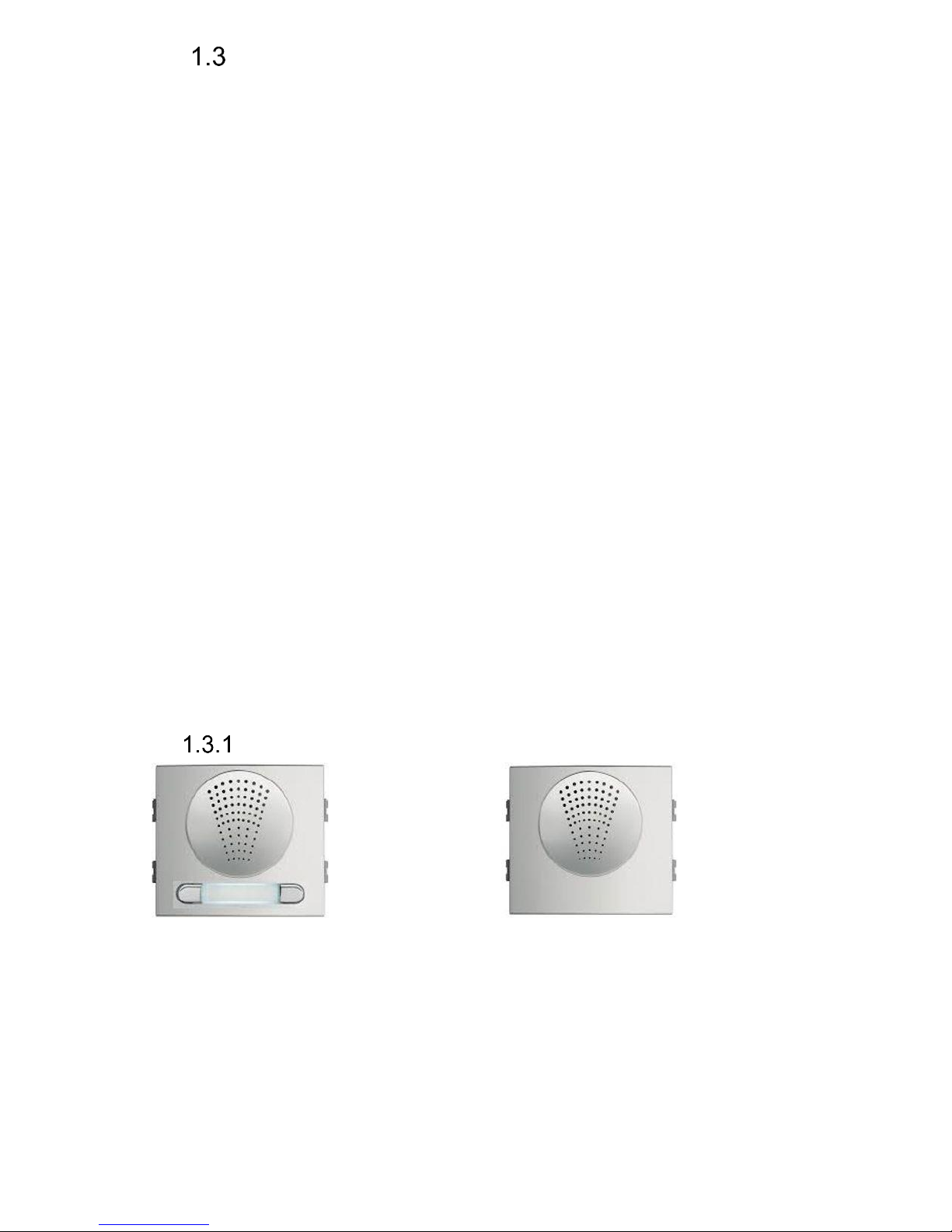
Voice modules without a camera
Basic module Basic modular Skyline module
1AP201 7415IP
Page 9
IP VarioBell - installation and operating instructions
9
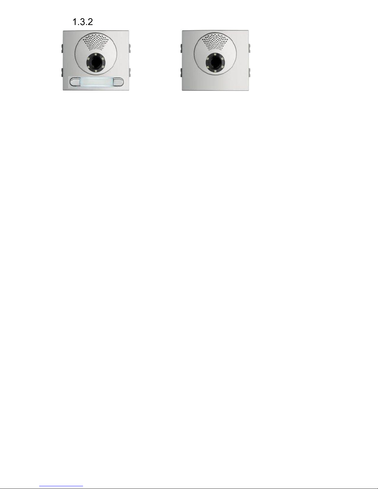
Voice modules with a camera
Basic module Basic modular Skyline module
1CP201 7421IP
Page 10
IP VarioBell - installation and operating instructions
10
Push button modules and keypad
The Fermax Skyline expanding push button
modules and a numeric keypad are the Fermax
Skyline VDS / BUS2 modules. The Fermax
Skyline expansion modules are connected with
the 6-core Fermax cable, which is always a part
of each Fermax Skyline expansion module.
The Fermax keypad is automatically detected in
the system, it does not need to be programmed.
Also it does not matter where the Fermax keypad
is connected.
The Fermax Skyline VDS / BUS2 push button
modules are connected in an independent order
of the numbering of the push buttons. The
Fermax Skyline push buttons numbering is
programmed in the usual Fermax way – by
pressing the push buttons in the order from the
first to the last (see more below).
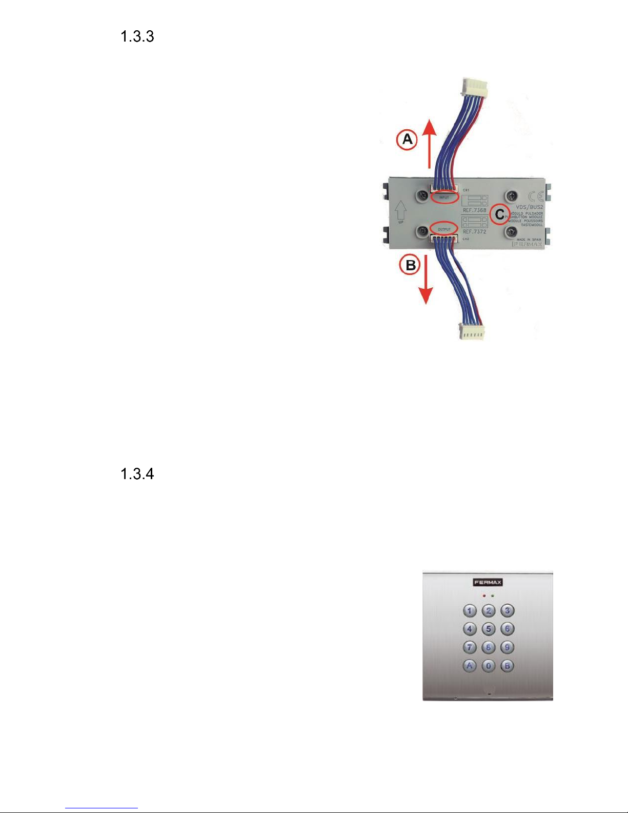
The principle of the connecting the expanding
modules (C) is shown in the figure.
Direction A - (input) is the cable leading to the basic (voice) module.
Direction B - (output) is the direction to the last module on the bus.
The position and the order of the expanding modules does not affect the
numbering of the push buttons. This is done in the programming sequence (so
called „push buttons mapping“) when everything is connected.
Numeric keypad
The numeric keypad is the original Fermax Skyline VDS/BUS2 module. It
is connected with the 6-core Fermax cable, which is always a part of each
Fermax Skyline expansion module.
The Fermax keypad is automatically detected in the system, it does not need to
be programmed. Also it does not matter where the Fermax keypad is connected.
Its presence in the system can be verified on the main
Status page in the programming web interface of the
doorphone. The keypad is detected with the first restart
after the keypad´s connection.
The selection is entered by consecutive pressing of the
number buttons, the key B (or the Bell sign according
to the type of keypad) must be pressed first to enter
the password. To hang up the call (to teminate the call),
press the key A and the doorphone will hang up at any
time. When entering an IP address for P2P direct dialling, use the key B as the
dot (.) in the IP address.
Page 11

IP VarioBell - installation and operating instructions
11
Mechanical parts
All mechanical parts are the original Fermax Cityline (valid for versions
1AP201IP or 1CP201IP only) or the original modular Fermax Skyline series.
Page 12
IP VarioBell - installation and operating instructions
12
Mounting of IP Fermax
Mounting on the wall
For surface mounting on the wall use the original
Fermax Cityline or Fermax Skyline series of mounting boxes.
Mounting is done by screwing on the wall, for example with
anchors. As an example, the figure shows a surface
mounting box for 1 module. Mount the surface box at the
correct height of 1,7m above the floor/ground.
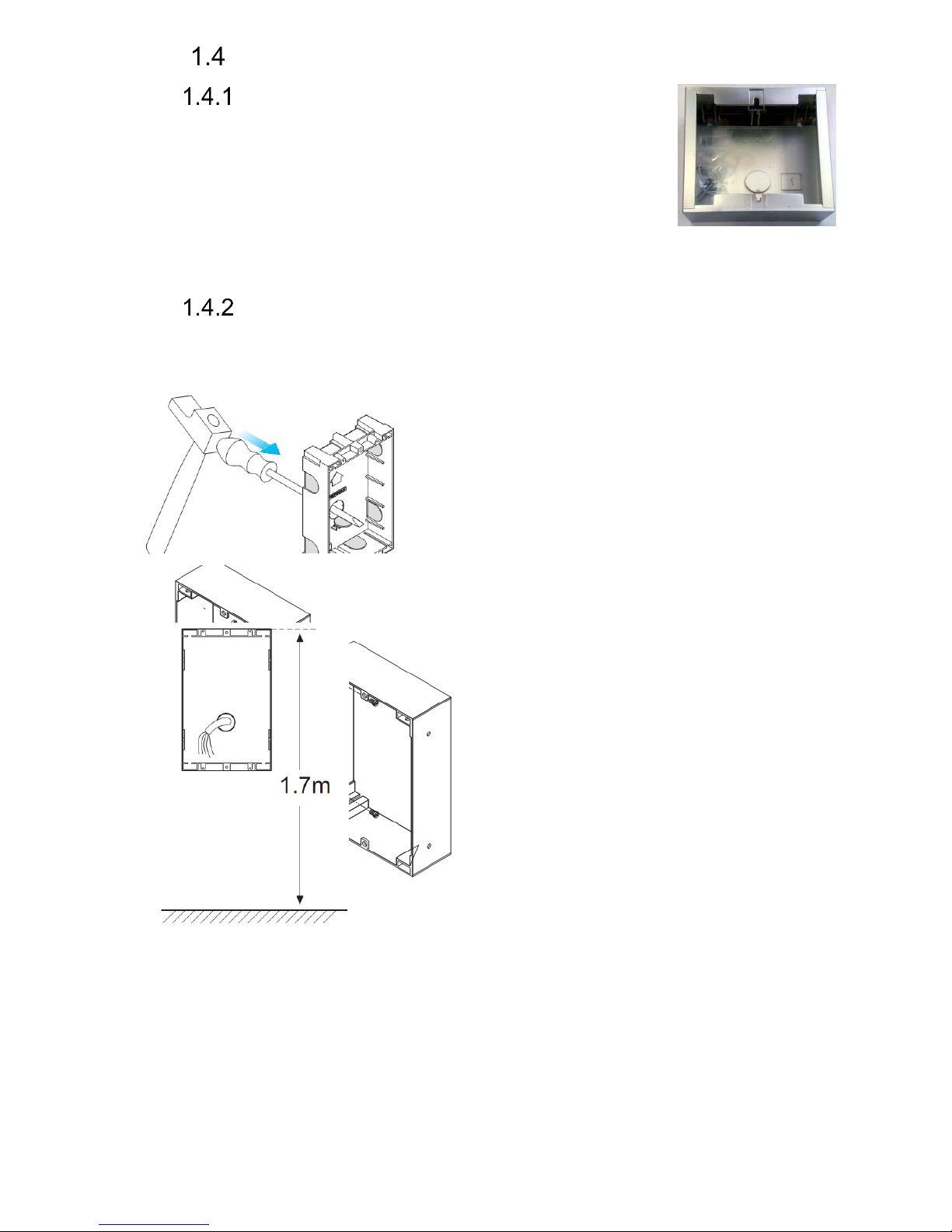
Mounting into the wall
For flush mounting into the wall use the original Fermax Cityline or Fermax
Skyline series of mounting boxes.
1. Prepare the flush mounting box
2. Principe of connecting flush mounting
boxes next to each other. Use the original
Fermax joining bolts (ref. 8829) to connect
the flush mounting boxes.
3. Mount the flush box at the
correct height of 1,7m above the
floor/ground.
Page 13

IP VarioBell - installation and operating instructions
13
Connection of IP-Fermax
The IP-Fermax contains the main board, optionally a camera board in
video version. The main board always comes with two push buttons on the
board. In the versions 1CP201IP and 1AP201IP both push buttons are used. The
modular Fermax Skyline series does not use any of these push buttons on the
main board. Only the Fermax Skyline expansion push button modules are used
in this case. Number of push buttons depends on the programming (consecutive
pressing of all push buttons in the selected order, more details are explained
later on). Up to 200 Fermax Skyline VDS/BUS2 push buttons and a Fermax
VDS/BUS2 numerical keypad can be connected to the main board. The main
board is equipped with two inputs (two door sensors or two exit buttons) and two
switches (relays). By using two programmable virtual relays you can control two
remote relays via http commands.
IP-Fermax main board
The main board is the same for all models of the IP-Fermax doorphone
and it differs only if the camera module is connected or not. There is always a
PoE module (according to the norm IEEE802.3af), connector for connecting
expansion modules, LED name card illumination, MicroSD card reader slot and
two switches (relays).
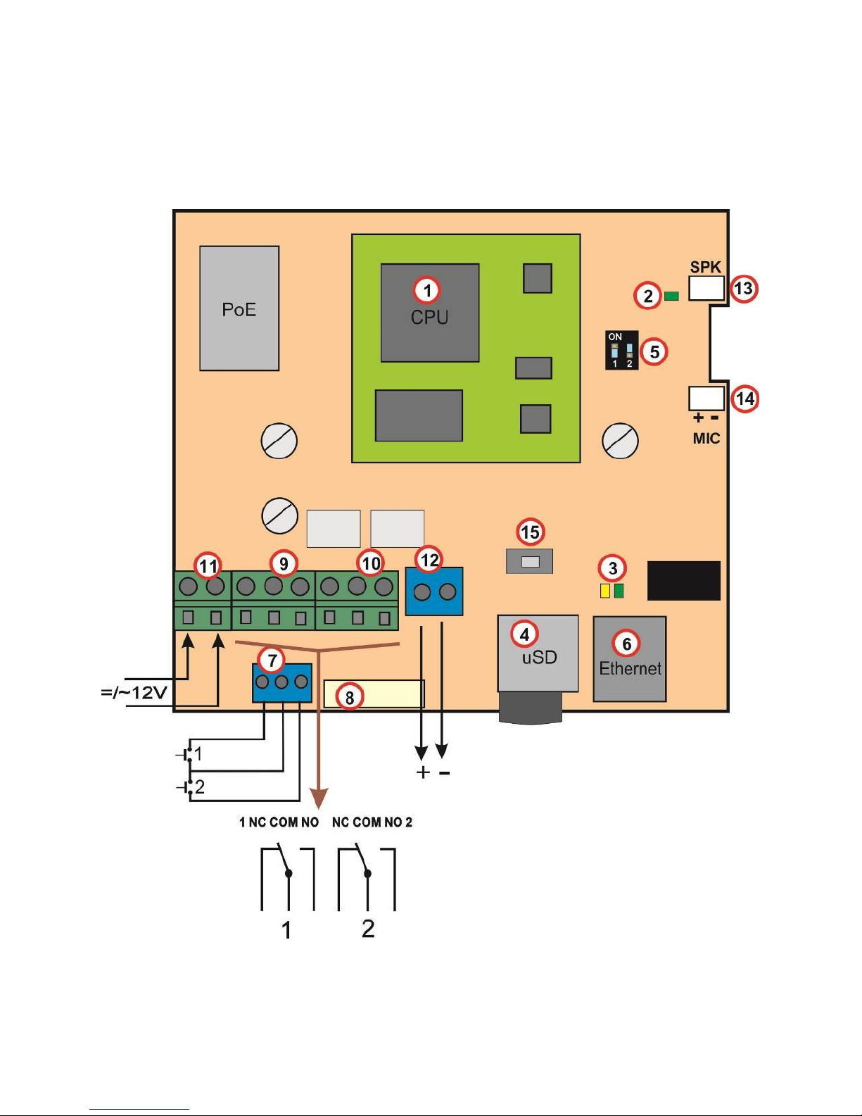
All functional and connected elements are marked with a number in a
red circle.
1. CPU board (processor module)
2. LED green – powering of the doorphone is alright
3. LED for checking network activity, green = connection of 100M LAN, yellow
= data transfer on LAN
4. Slot for MicroSD card – insert the card before switching on the doorphone
and do not pull it out during the entire operation of the doorphone!
5. DIP switch
1 – always on (used for factory service only)
2 – off, when it is „on“ during the start, then a default
IP address 192.168.1.250 and a default style are
set. Name is admin and password is 1234. To show a video
stream, name is video and password 1234 (if required). The
operational position is off.
6. Connection of the UTP cable (Ethernet, LAN, network)
7. Two switches (the middle clamp is common for both switches) for door
sensors or exit buttons (programmable)
8. Connection of cable from expansion modules – 6-wire Fermax cable
9. Terminal block of the switching contact of the first relay (NC= normally
closed, NO= normally open and COM= common, middle clamp/pin)
10. Terminal block of the switching contact of the second relay (NO= normally
open and COM=comman, middle clamp/pin)
Page 14
IP VarioBell - installation and operating instructions
14
11. Input for powering of the IP-Fermax 12V AC / DC (consumption approx.
300mA max.). We recommend using direct current (DC) type of power
supply.
12. Output 12V DC, max. 300mA, e.g. for powering of a low consumption
elektrical lock when there is a PoE type of power for the IP-Fermax
doorphone.
13. Connector for the speaker
14. Connector for the microphone (pay attention to the correct polarity)
Page 15

IP VarioBell - installation and operating instructions
15
15. Programming button (after pressing it for 5 sec., the IP-Fermax doorphone
will switch to the mapping mode to allocate connected push button modules.
When you press the programming button once again, it will save the mapping
result to its memory)
Page 16
IP VarioBell - installation and operating instructions
16
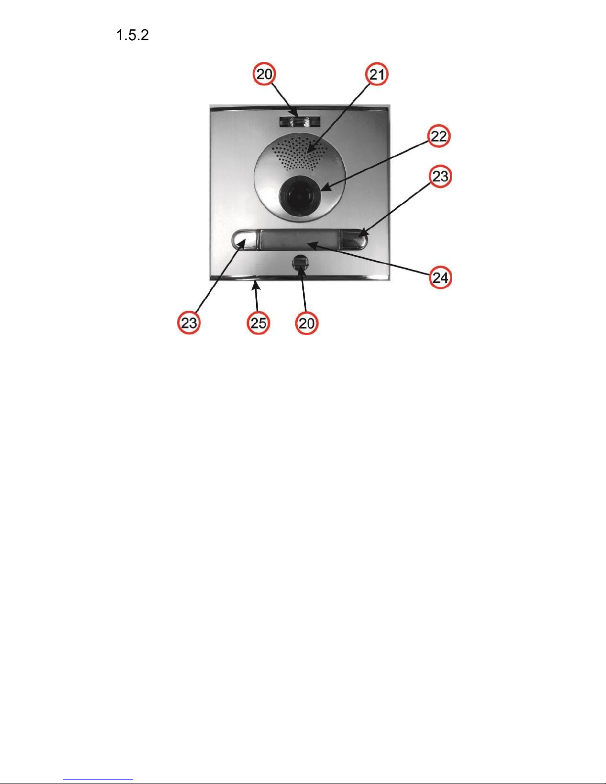
Front panel
20. Mounting holes for holding the front panel. After installation close the top
hole with a supplied plastic cover with Fermax logo. The bottom hole is
covered with a supplied silver colour cover. Both covers and screws are
always delivered as accessories with the doorphone.
21. Speaker.
22. Camera wide angle 120° with illumination white LEDs and an ambient light
sensor for swtching on the illumination LEDs.
23. Push buttons which always come soldered on the main board. Depending
on the type of front housing you use them or do not use them (defined during
the programming-mapping sequence of push buttons)
24. Name card, exchanging a name card is described later on. The name car dis
illuminated with white LEDs (the illumination can be deactivated)
25. Microphone
Page 17
IP VarioBell - installation and operating instructions
17
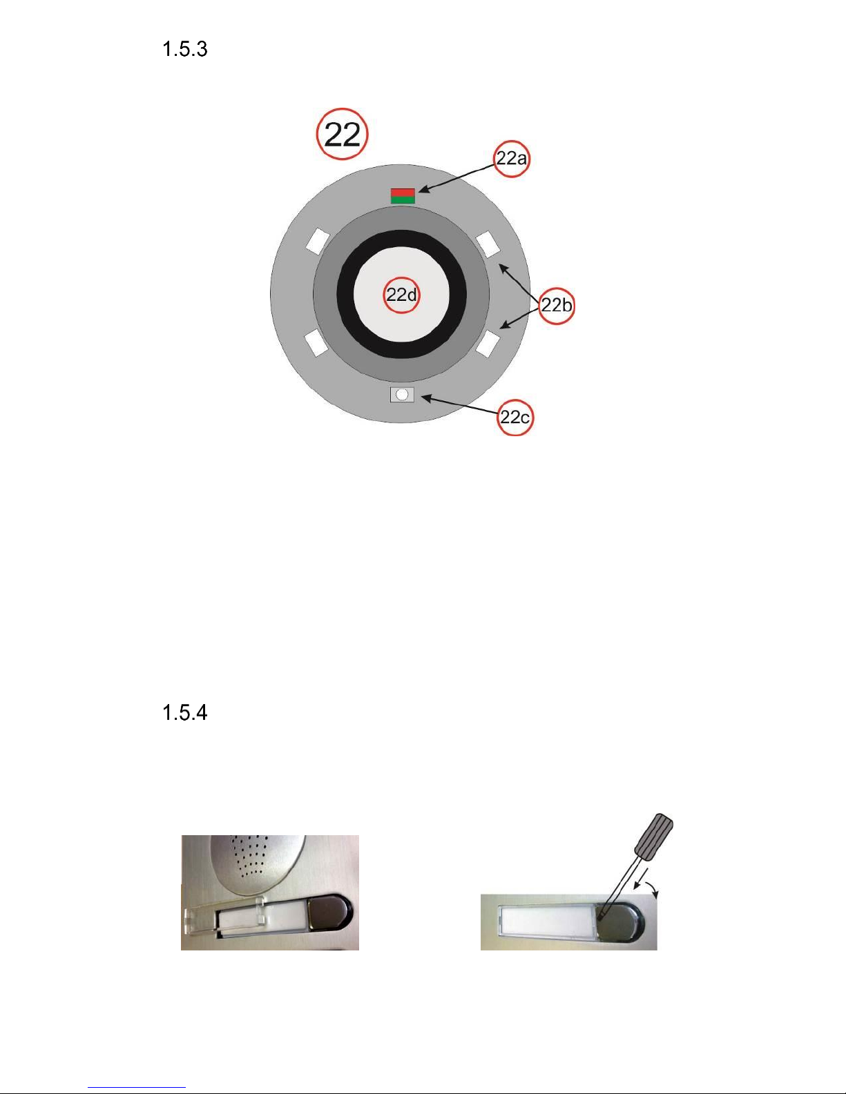
Camera (22)
On the figure below and the previous figure above (22) – detailed description
(valid for camera models only):
22a Two-colour LED for status indication. Red=establishing a call, Green=active
call, Orange=a switch is switched on (you need to set acoustic signalling of
the switch)
22b White LEDs for illumination of the space in front of the camera
22c Sensor of ambient surrounding illumination for controlling of name cards
illumination and camera illumination
22d Objective of the camera. View angle is 120°, max. resolution 640x480.
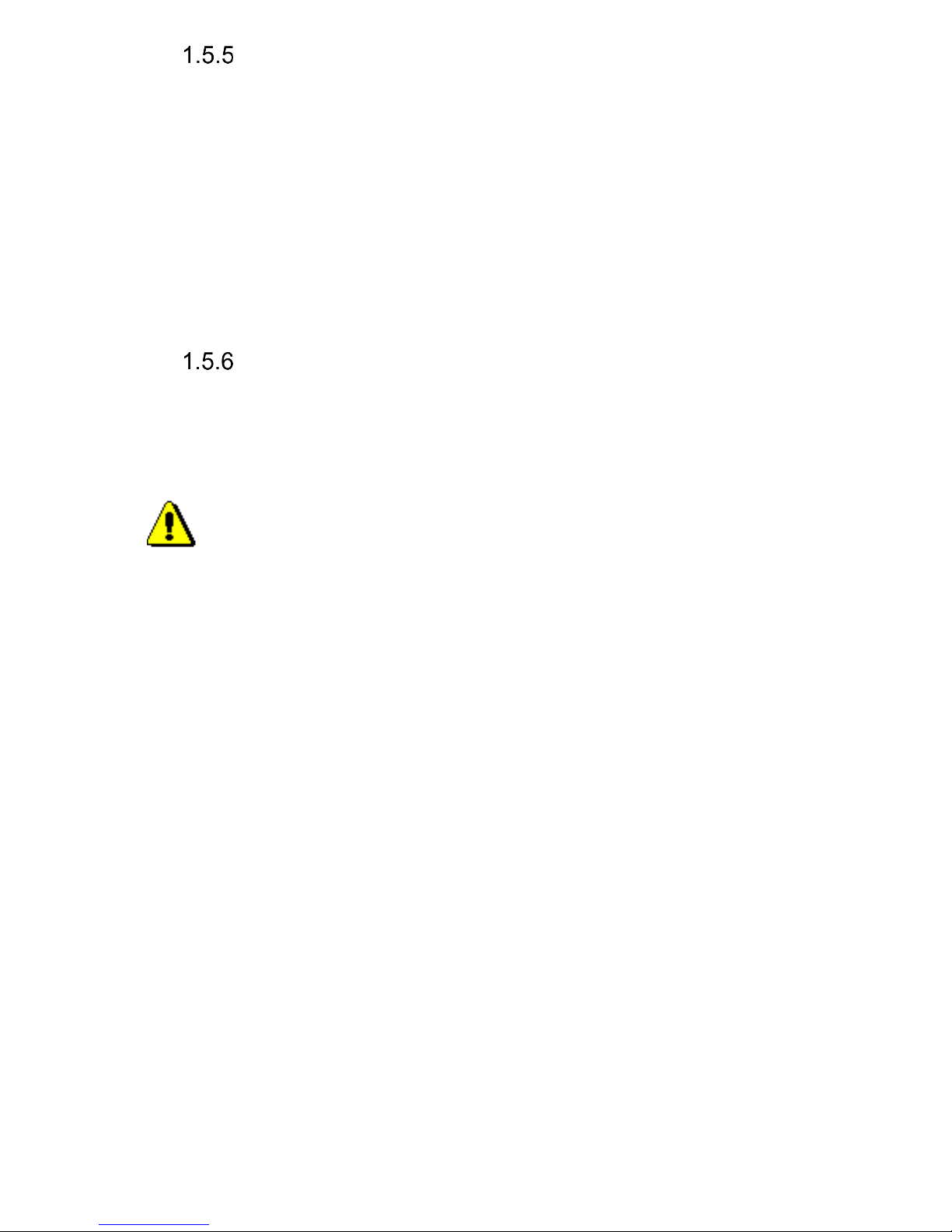
Replacement of name cards
The name cards are removed from the front of the doorphone as shown
on the figure below. Be careful when opening the front plastic cover to avoid
damaging or scratching the front panel or the plastic cover of name cards. The
name card cover is actually a tray where the label paper must be loaded.
Page 18
IP VarioBell - installation and operating instructions
18
Power supply - clamp (10)
12V power supply can be direct (DC) or alternating (AC), it is
inpependent on polarity, from 12V the max. consumption is 300mA.
The power supply can be used also for powering the elecrical lock, then
we recommend to use 12V/1A.
You can also use a 24V direct current (DC) power supply. Usually it
is used at instllations where there is a power supply already, for example at
attendance systems or at sliding gates. You must not use an alternating current
(AC) power supply, you can use a direct current (DC) power supply only. It is
inpependent on polarity.
Micro SD card (4)
The microSD card is used for savig user audio files. In the future it will be
used for storing images, videos and audio files. Then the MicroSD card will be
used as a recorder.
If use choose a user audio tone and the card is not inserted in the
doorphone, then only the audio tones of the basic signalling will be used.
Do not eject the SD card during operation of the doorphone!
Page 19

IP VarioBell - installation and operating instructions
19
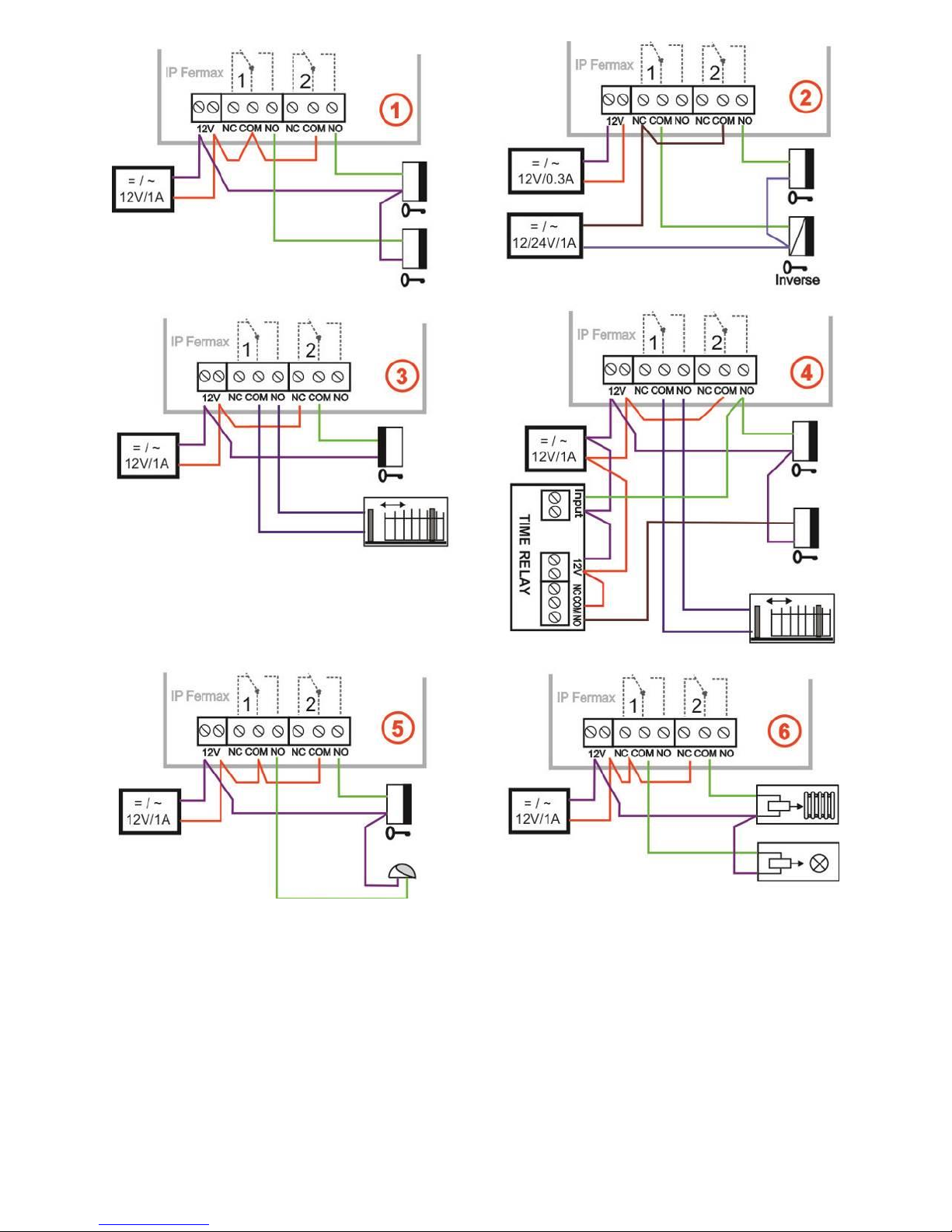
Connection of switches
Examples of switches connection is shown on the next page. There are just
a few basic examples, but it gives you a good guidance how to connect individual
circuits (red circle = example number).
1. Basic wiring - 2 electric locks and the possibility of controlling two doors
independently (switches 1 and 2 are monostable) this scheme also applies
to the gradual opening of the door. This connection is the most common, one
common source powers the IP-Fermax doorphone and two electric locks.
The current load of the power supply depends especially on the electric locks
used. The standard lock has a current consumption of 0.6A - 1.0A, and it is
also necessary to consider whether it is possible to switch on both switches
of the electric locks simultaneously. If not, choose a 2A power supply source
instead. If you use low consumption electrical locks, then 1A power supply
source is fully compliant.
2. Two sources - the possibility to use independently two power supplies, one
for the IP-Fermax doorphone and the other for electric locks. The electric
lock 2 is inversely connected (fire escape door).
3. Combination of doors with electric lock and gates in fencing.
4. Extending the previous example to two doors with a gradual opening (this
function is set in TimeRelay - external module)
5. Combination of electric lock and auxiliary bell. The auxiliary bell switch can
be in the switching mode of the call (responds to all push buttons) or
switching the switch from the selected push button, then the switch responds
to only one selected push button.
6. Switching lighting (eg road to the building) by switch 1 (setting the switch
from call to switch). Switch 2 - heating control according to the weekly
schedule - the time profile table synchronizes the selected switch. Attention!
A contactor must be used (the IP-Fermax doorphone must not switch
230V!).
The examples in the figures below are principal examples only.
Page 20
IP VarioBell - installation and operating instructions
20
Page 21
IP VarioBell - installation and operating instructions
21
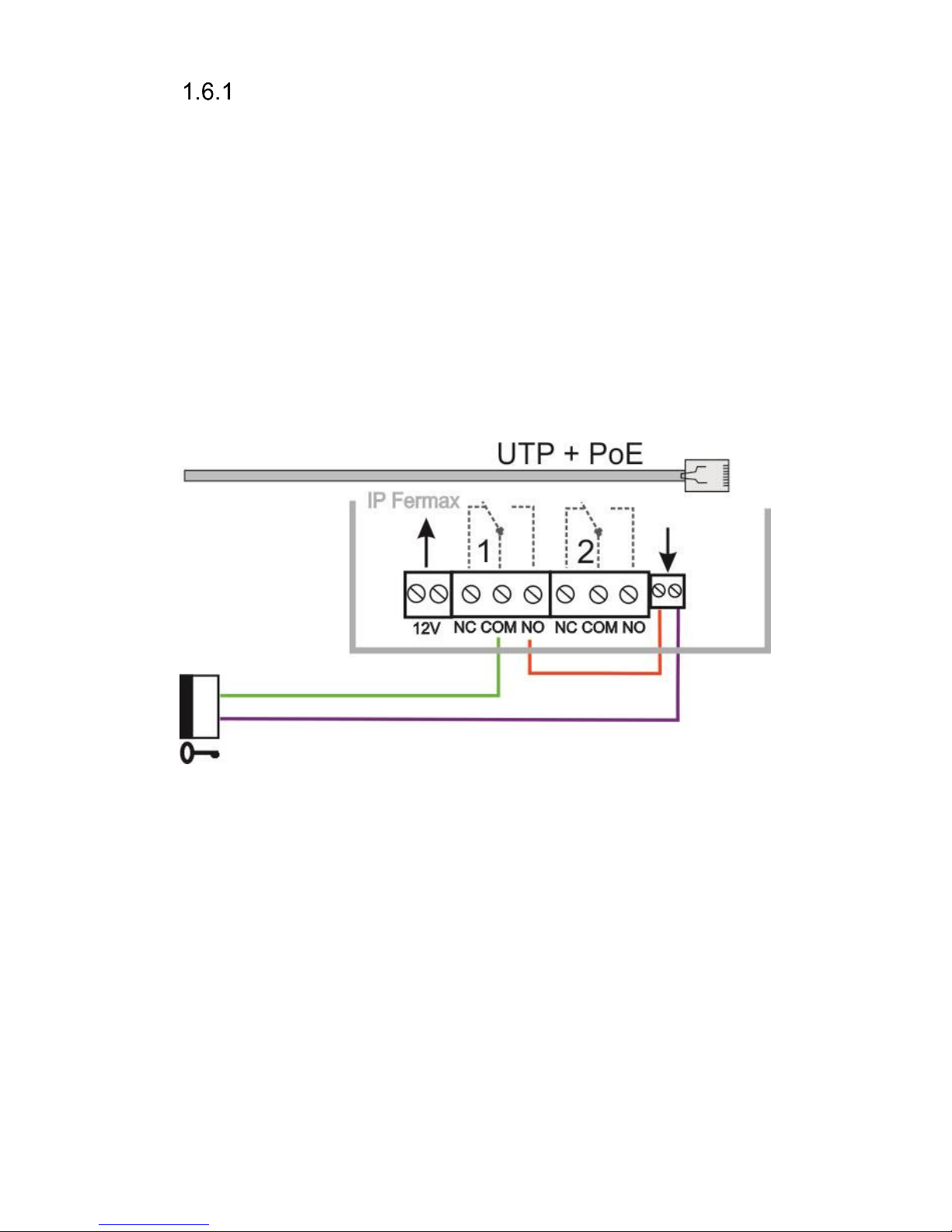
PoE power supply source
The IP-Fermax doorphone is equipped with a circuit for PoE powering over
UTP cable. If you have a PoE power switch, or you own a PoE (a box of the size
of the AC adapter plugged into the UTP cable - according to the IEEE802.3af
standard), you no longer need a 12V power for the doorphone´s function.
If you use an electric lock to open the door, you must use the power supply (only
in the relay contact circuit) or use a low consumption electrical lock and then use
the output terminal "12V output" (the terminal marked "12"). For PoE power
supply source, there is 12V/300mA available.
Attention, ensure that both electric locks are not be active at the same time.
This can be achieved, for example, by synchronizing the switches and setting
the door's successive opening (the setting is described in the chapter on the
setting of the switches – relays setting)
Page 22
IP VarioBell - installation and operating instructions
22
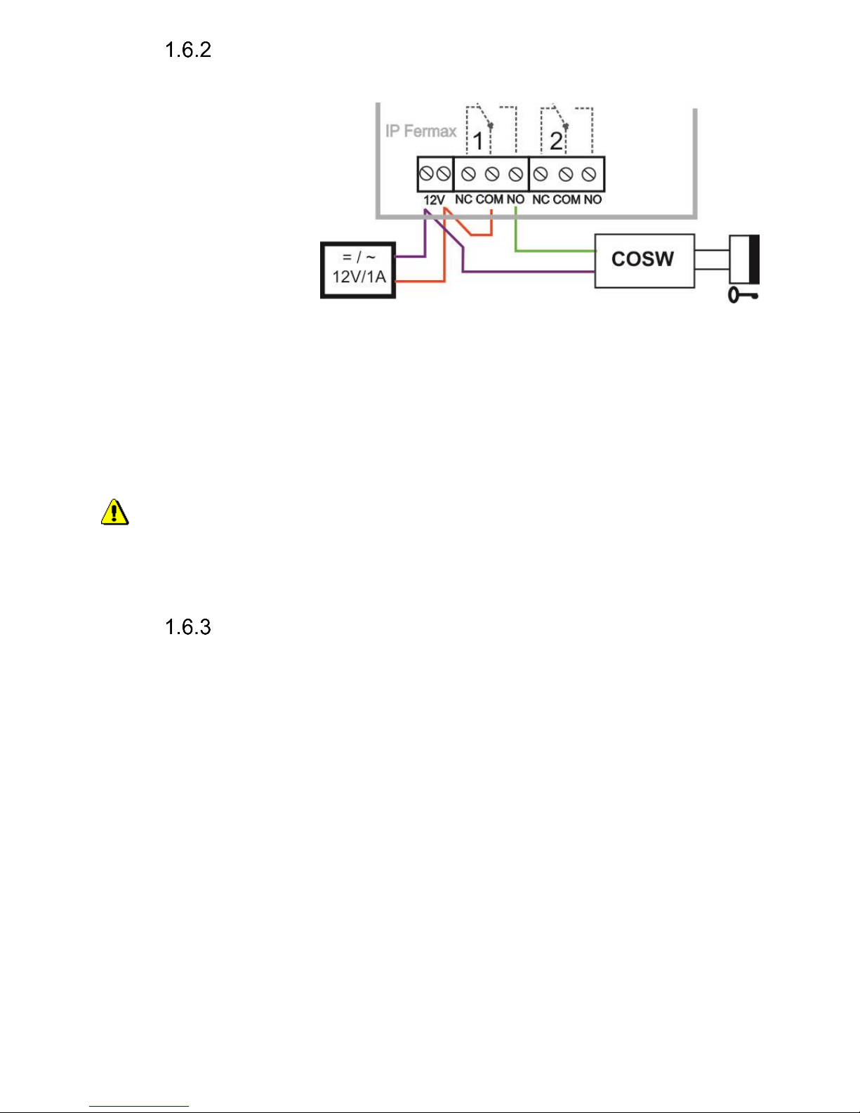
Code relay (COSW)
For the switch, the code relay function (COSW-CodeSwitch) is available.
In particular, it serves to
secure transmission of
information on switching
the electric lock. When
using this function, it is
not possible to activate
this lock by attaching or
disconnecting the
voltage to the lock leads.
Activation is only
performed when the
serial information transmitted between the IP-Fermax doorphone and the code
relay board (COSW) is identical.
In the IP-Fermax doorphone you can set the Security code for the output
to activate the COSW code relay.
The code information is 8 bits, but the code entry is 4 bits with 4-bit security,
which is a total of 8 bits. Practically, this happens by activating the switch first by
transmitting the serial code and if it agrees, the code relay will connect the
electrical lock.
The code relay can be connected in parallel and thus extend the number
of switches, but you can never combine the electrical lock and the code
relay in parallel !!!
Use of door sensors – exit button
Door sensors can be connected to the IP-Fermax doorphone to a
maximum of two. It is used to retransmit information about the closed door. This
information is displayed on the Home screen (under the camera image) and also
transferred to UDVguard sw applications. Another option is to use SNMP.
The door sensor is either a part of the electric lock, or it is a common
magnetic contact used in the security technology. It is connected as an NC
switch on the terminal block (7) - as well as the magnetic contact from the Alarm
(Door Closed = Closed).
Inputs for door sensors can also be used as exit buttons. The IP-Fermax
doorphone´s setting allows you to select which switch controls this input. The
NO button is connected to the input and when you press the exit button, the
switch is switched on in monostable mode for the switching time.
.
Page 23

IP VarioBell - installation and operating instructions
23
Numbering of push buttons
After connecting the expansion push button modules, you must program
the push buttons numbering (to determine which push button has what number
– you need to create a relation to the party number in the phone book).
This is done similarly to the VDS Fermax system.
On the basic side of the IP-Fermax doorphone (above the MicroSD card slot)
there is a button (15).
How to assign numbers to the push buttons:
1. All expansion push button modules are connected, the IP-Fermax
doorphone is switched onPress the button (15) and hold it for 5 sec. (the
IP-Fermax doorphones starts beeping quietly)
2. Now press the buttons of the whole assembly so that the first press =
push button # 1, the second press = push button # 2 and so on until the
last push button.
3. Also include the push buttons on the basic (voice) module in this proces
4. Press the button (15) briefly to save the programming/mapping of push
buttons.
5. The check is on the Current status page - the number of push buttons
(buttons count) is the number of times you pressed the push button on
the whole assembly.
The keypad is not included in the programming/mapping and nothing is
pressed on the keypad. It is detected automatically.
If you want to omit some push button while programming, just press the
same push button again. E.g. the push buttons sequence should be 1-2-4-6,
then press the push button 1, the push button 2, the push button 3 and the
push button 3 again = this is number 4), the push button 4 and the push button
4 again (that is number 6).
Page 24
IP VarioBell - installation and operating instructions
24
Service of IP-Fermax
Signalling overview
Overview of signalling
The IP-Fermax doorphone is signaling acoustic states that can occur
during operation, additional signaling is via two-color LED (located above the
camera). The acoustic signaling for each state listed in the table below can be
turned off or the default beep tone is used or replaced by user sounds.
Status
Tone
LED
Start calling
Optional / user-programmable
red
End of call
Optional / user-programmable
goes out
Call is not possible (busy)
Optional / user-programmable
red
Confirmation of the code entry
Optional / user-programmable
green
End call alert
Optional / user-programmable
green
Switching on the relay switch
Optional / user-programmable
* red +
green
Error
Optional / user-programmable
-
Pressing the push button
Optional / user-programmable
-
Establishing a connection
-
red
Connection is established - call
-
green
Service mode (start boot)
green
Start Linux
red
Start of rescue WEB
red blinks
* - the indication is conditional upon switching on the acoustic signaling of the
respective switch
Visitor at door
Visitor at door is person who wants enter inside the building.
Push Button press – outgoing call
Outgoing call is call from the doorphone (started by the visitor). Then the
doorphone dials and a phone is ringing inside the building.
The push buttons of the doorphone have name cards with names and
functions of people inside the building. The visitor press appropriate push button
and the doorphone starts calling immediatelly (in case the push button is not
defined as the first digit of codelock) or there is some delay (a time period
Page 25

IP VarioBell - installation and operating instructions
25
between push buttons pressing) .The doorphone dials a preprogrammed
number. Dialling the number is different according to settings in the phone book:
1. Phone book position for selected push button must be permitted
2. Must be fill min. 1 from 5 phone numbers (or IP adresses in P2P mode)
3. At filled phone number is active time plan in appropriate time or no plan
is selected.
When is filled up more numbers then selection of phone number is up time
plan and next are numbers dial in order (1 – 2 … 5) or numbers might be dial
simultaneously and which is picked up first it has the talk.
Both versions of dialling might be combinated. For example is possible call
to 1. and 2. Phone number simultaneously. When call is not picked up until
certain time then number 3 is dialled.
Repeated button press might have following functions:
- Nothing happen
- Dial again
- Call is ended
Since version 3.0.38 is in guard IP Fermax new property that upon arrival
"SIP Ringing" or the "Session progress" will not pass audio, but lets local bell
ringing. But the video link (if offered by the counterparty in the SDP). Thus, it is
possible with a suitable videophone (eg. Grandstream GXV3275 - "Preview"
button) to see who is standing at the door, and accordingly it let in the building
or not, without having heard anything from IP Fermax.
Button press – code lock
Door entry IP Fermax buttons have feature of code lock. By progressive
buttons press you can activate appropriate relay. The codes for this feature are
either shared by all subscribers (relays setting) as same as individiual (each
subscriber has in phone book own priváte access code).
Caution: code might be done from available buttons only (for example
model IP IP Fermax has available 1 or 1 and 2)
When button number is first digit o any code then dialling from this button is
delayed about “time between button press” for code evaluation.
It is also necessary mention feature relay closing by press of selected button
(for example for function bell activation). This feature programmable in relays
petting.
Call
Door entry IP Fermax has adaptive ECHO canceller. The Echo dissapear
usually within first 5 seconds of call. The call is then full duplex. The end of call
happen:
- Called party hang up
- Call duration time is over (when is setup)
- By button press(when is setup)
Page 26

IP VarioBell - installation and operating instructions
26
Visitor inside building
By person inside building is person who is in communication with door
entry IP Fermax.
Outgoing call
Outgoing call is call from door entry (start by visitor). After door entry dial
is ringit phone inside the building. When call is picked up you can talk to visitor
at door and by code dialling you can activate relay. Door entry sends 10sec
before call end notification about time limit of call and by dial character (* / #) you
can prolong the call. By phone hang up the call is ended.
All transmission ways of info about button press are available (for example
code to activate relay) – either in “RTP channel – RFC2833” or in “SIP info”
and “inband DTMF”.
Incoming call
Incoming call is call to door entry (start by person inside building). After
dial of extension number or IP adress where is connected door entry IP Fermax
the door entry is ringing and after preprogrammed number of rings picks up the
call. You can talk. Possibilities are the same as outgoing call (activate relay,
prolong the call etc.).
Page 27

IP VarioBell - installation and operating instructions
27
Video
At models with camera is possible received video as follow:
- IP phone with LCD display
- PC – WEB browser
- PC with program iBell (www.alphatechtechnologies.cz)
- PC with general programm for video watching (for example VLC)
- Android device (smart phone, tablet) UDVguard (Google Play)
- Apple device (smart phone, tablet) UDVguard (iTunes)
Video formats: JPG, MJPG, H.263, H.264
Video for WEB:
Internet Explorer, Mozilla, Opera, Firefox… - (set of JPG pictures - Port 80)
it is used repeated http request „IPaddress/video.jpg“
programm PopUp (UDVguard) - (MJPEG stream - Port 80) is used http
request „IPaddress/video.mjpg“ (sometimes is reload necessary to run).This
video is more fluent and has less network strain.
Stream video for IP phones:
H.263 and H264 is established by IP Fermax door entry and IPvideo phone
over SIP/SDP protocol on standard SIP port. The video (as same as sound)
then runs by RTP protokol on ports agreed over SIP (usually 9078).
rtsp request „rtsp://IPaddress/video.264“
or rtsp request „rtsp://IPaddress/video.263
Video parametres:
JPG Pictures are created in IP modul and for all transmit protocols are the
same .The Size (resolution) of video is selected in "Video setting" on WEB.
Maximal resolution is defined by USB camera type and mostly is 640x480
Stream H.263 knows CIF resolution (352x288). It means bigger JPEG is cut
and smaller framed.
Frequency (1-15 picture./sec) JPG Picture is selected in "Video setting" on
WEB.
Frequency MJPG and Stream H.263 coming from camera. It is used every
second and reset is between 7-15 pictures/sec. Higher resolution brings
decreasement of Pictures/ sec. (limited by processor efficiency)
Ports:
Port 80 for http (WEB pages even JPG / MJPG video on them)
Port 5060 for SIP
Ports RTP with oposite party communicates over SIP. Usually Port 7078
suggested for audio and Port 9078 for video
Port 554 video( H264 and H263) provided by door entry (server) protocol RTSP
Page 28

IP VarioBell - installation and operating instructions
28
Parametres programming
Parametres programming is performed by ordinary WEB browser.
(Caution! version of IE V7 and lower are not supported).
WEB interface access
For successful display of WEB interface of IP Fermax door entry we go
through some details.
Field length - names, titles, codes, passwords have fix length 40 characters.
- URL and etc. have max length 255 characters
What you should know
In doorphone IP Fermax is a double DIP switch. Individual switches should
be in the positions shown.
1 – on
2 – off
Meaning of each switches:
1. Always position on, this switch is only used in the manufacture or repair
service.
2. If the position on at power (or reset) so in doorphone is set the default
IP address 192.168.1.250 and uses the default style. The name is admin
and the password is 1234. To see the video is the name video and
password 1234 (if required). The operating position is off.
Warning: If you get into a situation that you do not know the IP address set
in IP Fermax or have forgotten your password, so there is reason to use the DIP2
switch, switch it to the ON position and restart IP Fermax. Then you change the
settings eg. Passwords or network settings. Remember to switch DIP2 into
operating position DIP2 = off and click save and restart. After rebooting, IP
Fermax is now all set according to the changes.
You should also dedicate attention into which PC network you are
connected. Default door entry IP address is 192.168.1.250.
When is your PC in network setup also on segment 192.168.1.xxx then might
caused a problem in network just by same IP address etc. 192.168.1.250.
In this case we recommend temporarily disconnect device from network.
When your PC is setup to different network segment than 192.168.1.xxx two
possibilities are available:
1. In PC you have system Windows 7 or 8, then you can setup „network
setting“ – „Protocol IP version 4“ – „Property“ – specify“ and here add IP
address in PC segment of door entry for example. 192.168.1.10
Page 29
IP VarioBell - installation and operating instructions
29
2. Generally in PC setup you program temporarily own IP address.In PC
door entry segment for example 192.168.1.10. After change of door entry
IP address you have return setting in PC back.
Then you can setup parameters of door entry including IP address and after
restart of IP Fermax door entry you can login to door entry WEB page on new IP
adress.
Login
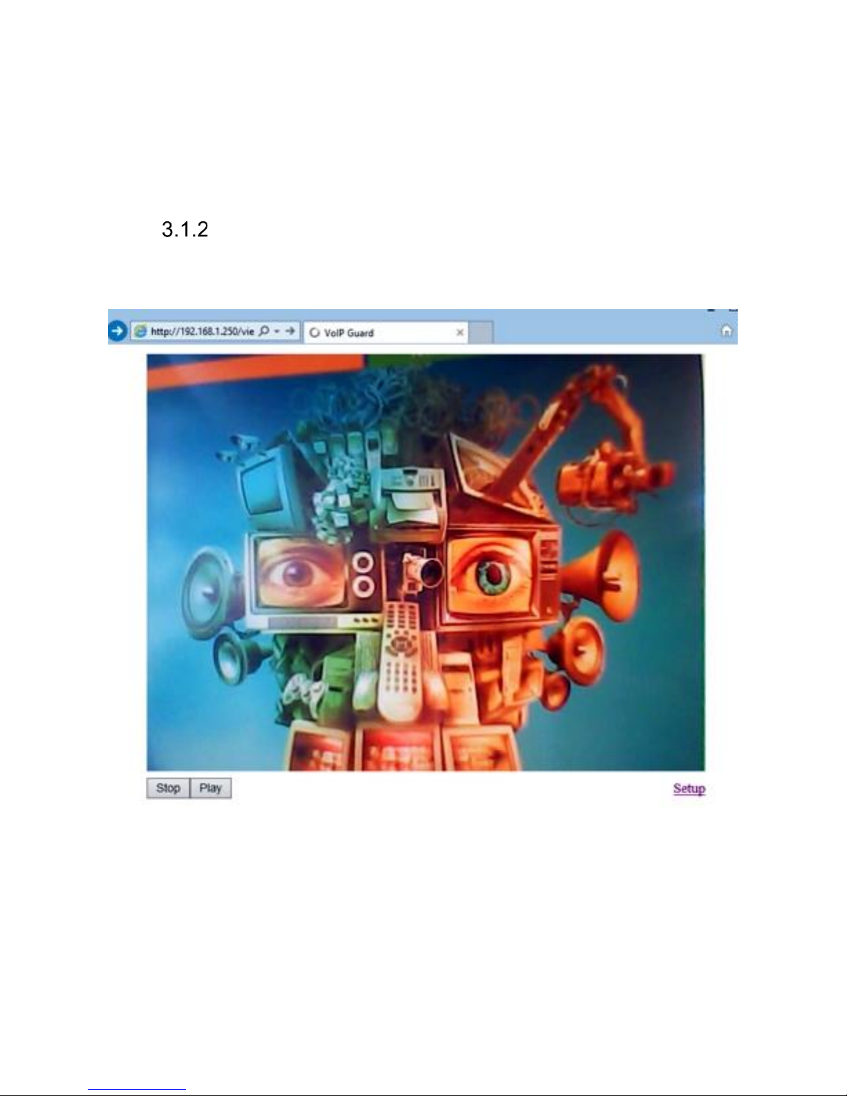
In your WEB browser write IP adress of IP Fermax door entry in default it is
192.168.1.250. you can see picture from camera as bellow – „home screen with
video"
Under picture from camera (at models without camera is empty frame only)
are on the left buttons Stop – to stop video and Start for run video again. On the
right is description Setup – after clil on it will be display request for login data.
Write username and password. Username is allways „admin“ and
password is „1234“ (adjustable in settings). (To see the video is the name „video“
and password „1234“ - if required).
You enter now to first petting page of door entry IP Fermax. On this page
is display „Current status“. All necessary data about door entry status are here.
Page 30

IP VarioBell - installation and operating instructions
30
Current status
Current status display basic data about IP Fermax door entry status. It
displays Firmware version,door entry model, options connection (camera), SD
card, MAC adresses, current time, network setting, door entry mode (P2P or
SIP server), registration status and small calls statistic.
Page 31

IP VarioBell - installation and operating instructions
31
Language settings
After language selection please don’t forget click on „Save changes“.
On the right top corner is display flag of current used language in whole WEB
interface. After click on flag accessible language will be displayed. After
language selection please don’t forget click on „Save changes“ otherwise
language selection wont be performed.
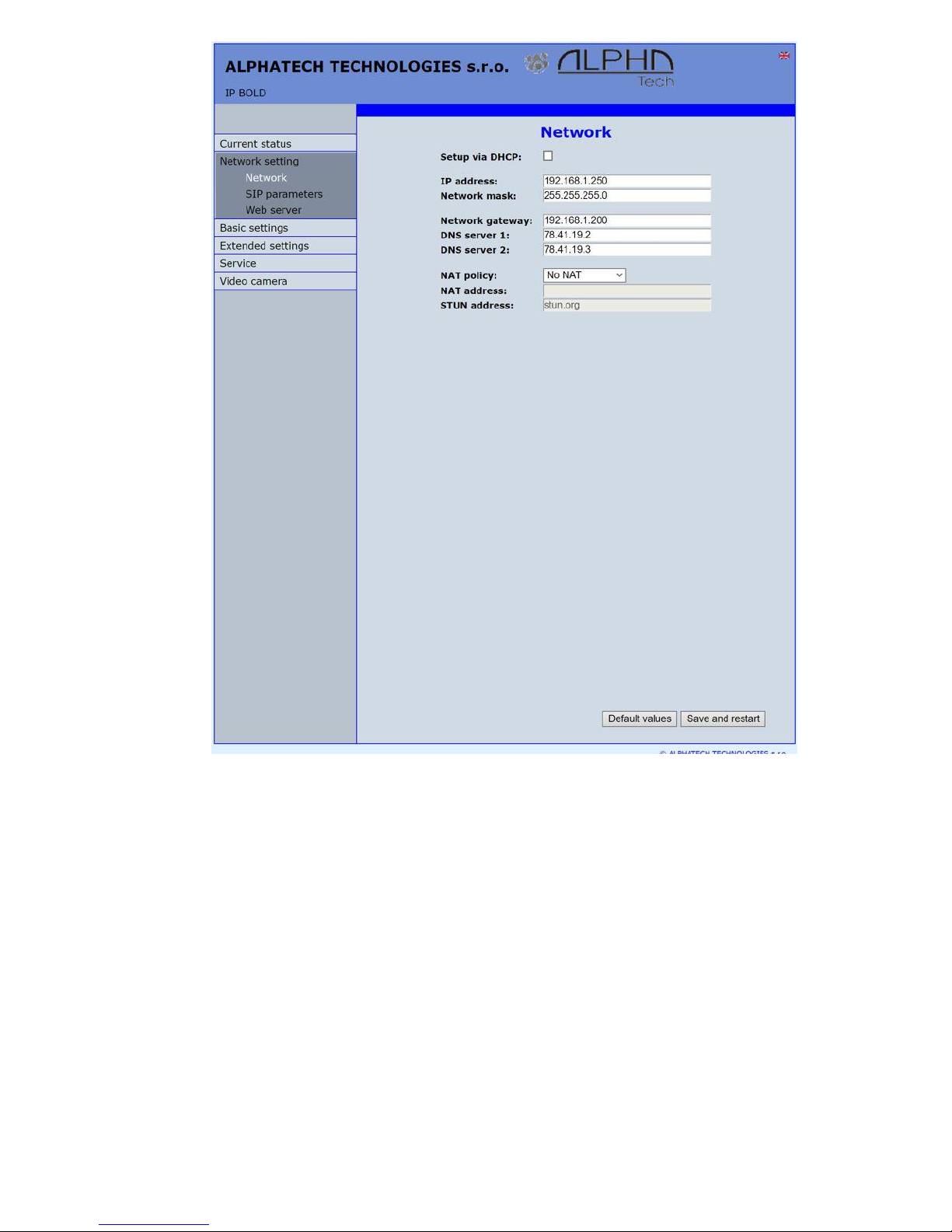
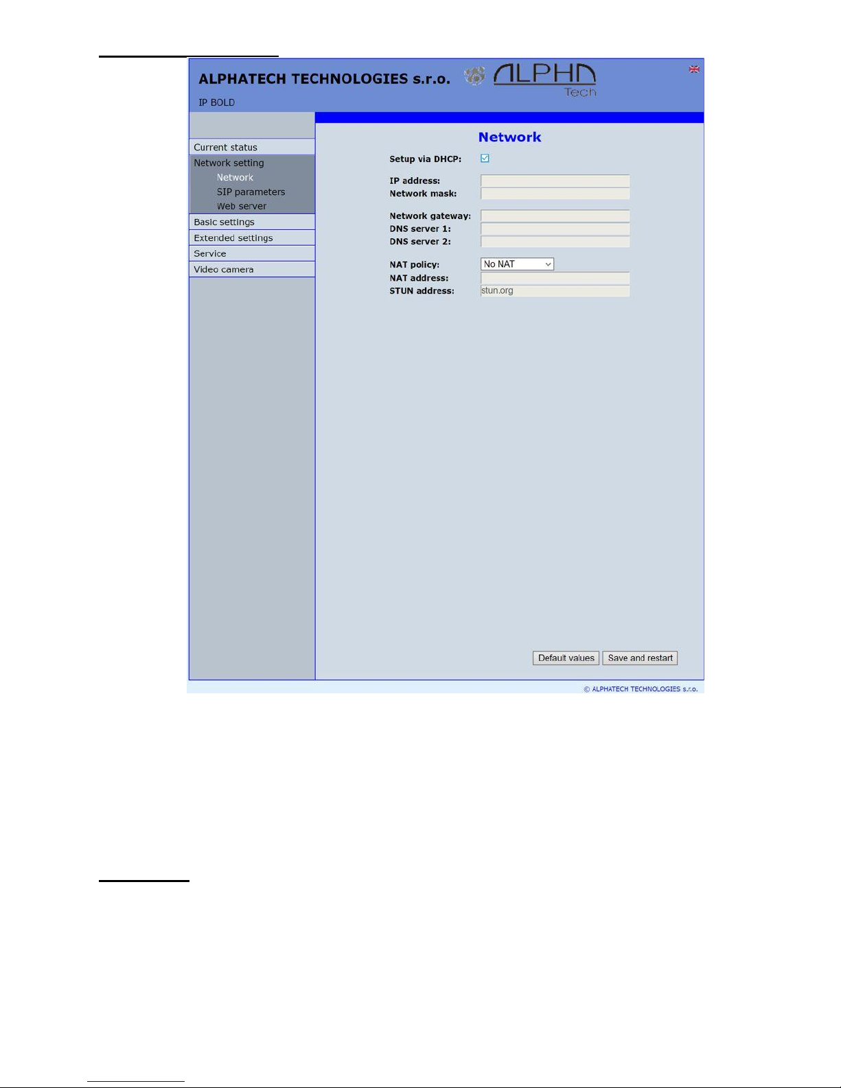
IP network setting
IP Network setting
Network settings you find in menu „Network setting“. You can select using
of fix IP adress or dynamically assigned by using DHCP.
Configuration of fix IP adress:
Page 32
IP VarioBell - installation and operating instructions
32
After performing of required changes please don’t forget click on „Save and
restart“.
Setup via DHCP - ON / OFF using DHCP assignment of IP adresses
IP adress, Network mask – IP adress setting, mask. In case of emergency
please contact your network administrator
Network gateway – Router IP adress (Internet connection)
DNS server 1 and 2 – IP adresses of primary and secondary domain server
NAT policy - there is the choice of what kind of translate IP addresses used
NAT address - used for network traffic through the router (modifies transcription
of the original or destination IP address)
STUN address - the IP address of the STUN server (see. page. 6)
Page 33
IP VarioBell - installation and operating instructions
33
DHCP configuration:
After performing of required changes please don’t forget click on „Save and
restart“.
DHCP – by mark of this checkbox as same as saving and restart will be assigned
to door entry IP Fermax - IP adress by DHCP.
NAT policy - there is the choice of what kind of translate IP addresses used
NAT address - used for network traffic through the router (modifies transcription
of the original or destination IP address)
STUN address - the IP address of the STUN server (see. page. 6)
Important: if you use DHCP setting then DHCP assign IP address to door entry
automatically and network administrator will assure your current IP address to
be able watch video in WEB browser. Therefore this dynamically assigned IP
address might be changed due for example power failure we recommend use
dooe entry IP Fermax with fix IP adress.
Page 34

IP VarioBell - installation and operating instructions
34
SIP setting
The door entry IP Fermax might operates in 2 basic SIP modes. It is
either SIP server – door entry registration is performed to SIP server and then
you call to phone numbers assigned by SIP server or Peer to Peer (P2P) –
door entry call exact IP adress and SIP server services can´t be used.
Mode SIP server
After performing of required changes please don’t forget click on „Save“.
Display name - name by which is device presented in network (for example will
display as door entry name in programms iBell, UDVguard)
SIP User Agent – for easy inastallation is possible use the SIP user agent. The
syntax of this string is not defined, but a common practise is „device name +
version“.
Page 35

IP VarioBell - installation and operating instructions
35
Account - unit name in SIP protocol (usually line number or name without
diacritics)
Auth.ID - name for SIP server registration
Password - password for SIP server registration
Send register – when registration is necessary (mostly yes) then this parametr
must be used
Registration server - IP adress or server name of registration server (in most
systems and installations is enough to insert IP adress).
Registration is performed on this server. When you dont mark send
registration then dont fill Registration server and IP adres sof SIP
server write to Proxy server.
Port - SIP port is usually 5060 or 5061
Expiration[sec] – expiration of SIP server registration (period of registration
request repeated sending)
Registrate after restart – when you mark then allways during restart will be
unregistrated
SIP server - IP adress or server name. Over this server connection is made.
When is not filled then connection makes on Registration server
(but you must mark Send registration)
Port - SIP port is usually 5060 or 5061
Outbound proxy - IP adress or proxy name where is determine where will be
sends door entry requests. If outbound proxy is setup will be
INVITE regest sends to outbound proxy adress. Outbound proxy is
used due NAT. When is not used dont fill up.
Port - SIP port is usually 5060 or 5061
SIP Transport - TCP or UDP, or automatic selection
Provisional code – determine if during ringing will be sends SIP code „180
Ringing“ or „183 Session progress“
Enable symetric RTP - by mark is ON. It means that door entry will not sends
by itself audio to RTP called party, but wait for called party to send
RTP. After sends data to same adress:port from which message
arrived. It is trick used for bridging NAT
Registration status display on page as visible on picture.
Page 36

IP VarioBell - installation and operating instructions
36
Peer to Peer mode (P2P)
After performing of changes please don’t forget click on „Save changes“.
Display name – name by which is device presented in network (for example
will display as door entry name in programms iBell, UDVguard)
SIP User Agent – for easy inastallation is possible use the SIP user agent. The
syntax of this string is not defined, but a common practise is „device
name + version“.
Account - unit name in SIP protocol (usually line number), it is recommended
to keep filled.
Outbound proxy - IP adress or proxy name where is determine where will be
sends door entry requests. If outbound proxy is setup will be
INVITE regest sends to outbound proxy adress. Outbound proxy is
used due NAT. When is not used dont fill up.
Page 37

IP VarioBell - installation and operating instructions
37
Port - SIP port is usually 5060 or 5061
SIP Transport - TCP or UDP, or automatic selection
Provisional code - determine if during ringing will be sends SIP code „180
Ringing“ or „183 Session progress“
Enable symetric RTP - by mark is ON. It means that door entry will not sends
by itself audio to RTP called party, but wait for called party to send
RTP. After sends data to same adress:port from which message
arrived. It is trick used for bridging NAT.
In active mode - P2P is possible to operate device, which require for their
function registration at the SIP server. This option will use new SIP phones,
which generally do not support P2P mode, as well as applications for iOS - Apple.
The principle of setting SIP phones and UDV guard, iBell with IP Fermax:
1. Mode of phone is SIP server registration is IP address IP Fermax
(registration or SIP server = IP address IP Fermax)
2. Name and password is the line number (we choose a numbering plan
so that each number occurred in the network only once, then for each
device, fill in name and password to register with this number).
Example:
• IP address of IP Fermax is 192.68.1.250 and the name (page SIP
parameters) is 250
• The IP address of SIP phone 1 is 192.168.1.200, fill in the registration
here - SIP server = 192.168.1.250 and name = password = 230
• The IP address of SIP phone 2 is 192.168.1.201, fill in the registration
here - SIP server = 192.168.1.250 and name = password = 231
Call to SIP Phone 1 is 230, calls to SIP phone 2 is 231 and calls to IP
Fermax is 250
Page 38

IP VarioBell - installation and operating instructions
38
WEB server
After performing of changes please don’t forget click on „Save and restart“.
WEB interface TCP port - posibility of chase usuall TCP port 80 to other
(security reasons)
Service password / Retype password – inserting of new access password
(instead default password 1234) – length max.40 characters (name
for access is admin)
Video on start page – Video ON/OFF on home page of WEB interface (mainly
from security reasons. When video is OFF it is accessable after
login with password only).
Protect video by password – further protection is secure access by password
to http://ipaddress/video.jpeg (camera picture). CAUTION! this
option caused non working video on SNOM phones !
Page 39

IP VarioBell - installation and operating instructions
39
Video password – inserting of new video access password (instead default
password 1234) – length max.40 characters (name for video access
is video)
Enable telnet – available only for special customization.
posibility ON / OFF access from telnet (name: root, pass: 8765). Use
telnet is not recommended, in practice, this possibility has
caused a lot of problems. Damage Doorphone IP Fermax
unprofessional intervention via Telnet warranty will be void
Doorphone IP Fermax.
Page 40
IP VarioBell - installation and operating instructions
40
Basic setting
In this part are setup user and most often changed parametres.
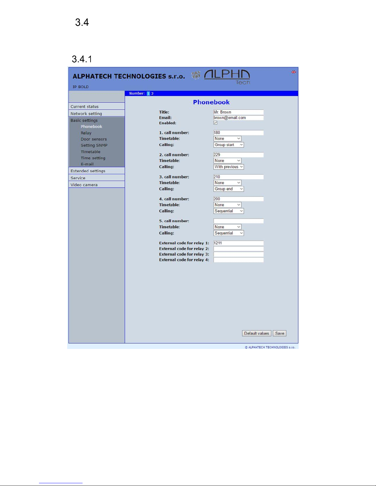
Phone book
After performing of changes please don’t forget click on „Save“.
The phone book contents 999 subscribers. For first 200 subscribers agree
subscriber number with button number. In this version of door entry – IP Fermax
is max = 200 button. Therefore first 2 subscribers are most important.
Position number in phone book is selected at top bar by click on
appropriate numeral. It is possible also listed by 10 (</>) or go to exact position
(all by selection in first – highlighted – row).
Page 41

IP VarioBell - installation and operating instructions
41
Every position of phone book allows insert up to 5 phone numbers with
possibility to join some of them (or all) into group and call group of phone
numbers simultaneously.
Title – This text has informative character only. In case of display using will be
name shown in list selection.
Email - to this email will be sent Info about missed calls with picture or video in
case of model (C) or with records (in case or recorder activation).
Necessary is setup Emailu – via follow.
Enabled – Item of phone book (also function of appropriate button) is working
hen is permitted only (marked). It has a sense for pensions, hotels
etc….)
1. call number – is phone number with highest priority. It is call as first (when is
used progressive dial mode). 1. Phone number will be dialled with compliance to
selected time plan only.
Time table – when is not selected then 1 number is allways active. Usage of 1
phone number might be limited by time plan.
Calling - allows create groups – via follow.
2. call number – is phone number which is dial as second (when is used
progressive dial mode). 2nd phone number will be dialled with
compliance to selected time plan and when is filled only.
Time table – when is not selected then 2 number is allways active. Usage of
2nd phone number might be limited by time plan
Calling - allows create groups – via follow.
3. call number – is phone number which is dial as thirth (when is used
progressive dial mode). 3th phone number will be dialled with
compliance to selected time plan and when is filled only.
Time table – when is not selected then 3th number is allways active. Usage of
3th phone number might be limited by time plan
Calling - allows create groups – via follow.
4. call number – is phone number which is dial as fourth (when is used
progressive dial mode). 4th phone number will be dialled with compliance to
selected time plan and when is filled only.
Time table – when is not selected then 4th number is allways active. Usage of
4th phone number might be limited by time plan
Calling - allows create groups – via follow.
5. call number- is phone number which is dial as fifth (when is used progressive
dial mode). 5th phone number will be dialled with compliance to
selected time plan and when is filled only.
Time table – when is not selected then 5th number is allways active. Usage of
5th phone number might be limited by time plan
Calling - allows create groups – via follow.
External code for relay 1,2,3,4 – here insert priváte codes for code lock. The
code lock might be completed from door entry buttons (mean
Page 42

IP VarioBell - installation and operating instructions
42
according buttons 1 – 2 in this model). Each subscriber has one cod
efor every relay.
Calling – description
The group means that 2 or more phone numbers creates group and those
Numbers are dialled simultaneously (all are ringing together). Who from dialled
Subscribers pick up first can talk and ringing to other subscribers in group
Will be ended.
Individualy – this phone number is dialled individualy. 42uet not in group with
any other number.
Group start – first phone number in group call
In group with previous – phone number in group. 42uet not first and also not
last.
Group end – phone number is last from the group
By this setting you can create for every subscriber up 2 groups or groups
with 5 numbers and make groups combination with individual phone numbers.
EXAMPLE: first phone number rings to operator – „Individualy“
Second phone number is „Group start“
Thirth and fourth phone number is „in group with previous“
Fifth phone number is „Group end“
– Those four phone numbers ringing in office together where are picked
up by other subscribers when operator is busy. In offices phones start ringing
after adjustable time.
Page 43
IP VarioBell - installation and operating instructions
43
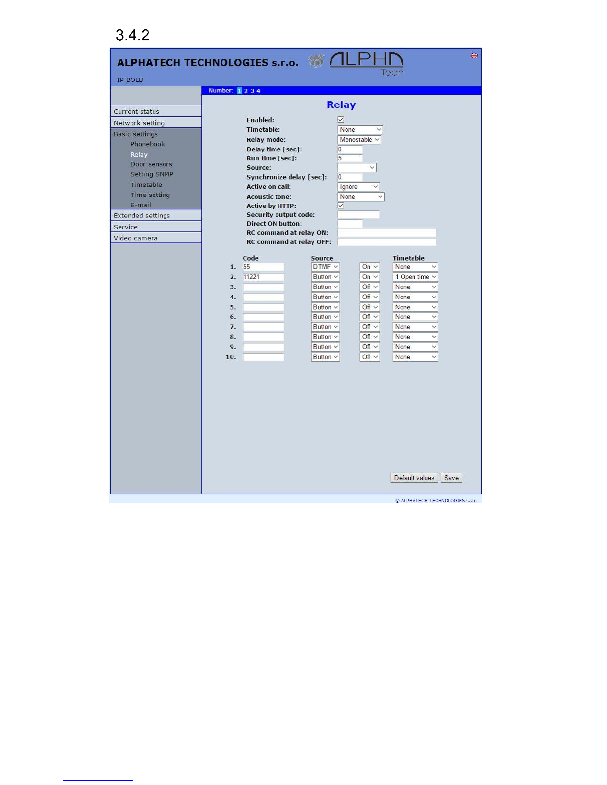
Relays
After performing of changes please don’t forget click on „Save“.
In relays setting are accessible 4 relays. The relays 1 and 2 is output of
relays contacts directly in IP Fermax door entry. Next 2 relays (3 and 4) is
possible use for remote relays (IP relays via follow) or as virtual relay usefull for
synchronization to allows creation of more difficult functions of relays. The relay
selection is perform by click to relay number in top highlighted row –
similiary as in phone book.
Enabled – relay function might be eliminated. 43uet his will be eliminated
synchronization signal for other relays. Meaning is for example when
you want temporarily prevent certain door opening. Then instead of all
codes cancellation and their repeated programming simply prohibit this
relay. After time out you can easily return relay with all codes to original
Page 44

IP VarioBell - installation and operating instructions
44
function. When such status repeats regularly (for example school) you
can use time plan.
Time table – defines time period when relay is working and hen not. For example
is shop operation time , school, etc..
Relay mode -
monostable – by code is closed and after preprogrammed timeout is
open. Using for electrical lock switching, sliding gates control, button
press signalling etc... (for control codes setting you must insert „ON” (via
follow)
bistable – by code is closed and stay closed till moment of open by other
code. For this purpose is beside control codes posibility select „ON” for
closing and „OFF” for open. (via follow)
Delay time – is time, between closing code evaluation and relay closing. It has
no influence for open code which is performed immediately. Closing
time is calculated from real relay closing. Using is for example:
progressive door opening, we setup same closing code for both relays,
by this delay is monitored walking time from first to second doors. This
feature is adjustable by synchronization as well. By synchronization
delay are available individual codes for each doors control.
Run time – relay closing time in monostable mode (time of electrical lock
opening)
Source -
Synchronize from time table - it is selected time plan for relay and 2 options
are available:
Monostable, then allways when setup time period in time plan is suitable
and time plan is active is perform closing for preprogrammed closing
time.
Bistable, then allways when setup time period in time plan is suitable and
time plan is active the relay is closed and out of those conditions is
open.
Synchronize with relay 1 – 4 – relay closing starts closing of the same or
other relay. Example for usage is sliding gate control, where by partly
opening you can create passage – door substitution. For this mode
relay must close for 1 sec in 2 times in sequence. Where period
between closing is created passage.( for example 6sec). The setting
make that for relay 1 select monostable mode with time closing 1 sec,
synchronization with relay 1 and synchronization delay 7 sec. In case
you need setup situation that for one code (55) relay 1 close 2 pulses
in sequence – passage creation and by second code (56) gate will be
closed then use not connected relay 4 for synchronization. Setting of
relay 1 is monostable, closing time 1 sec, synchronization with relay 4
and synchronization delay 7 sec. Codes for relay 1 closing are 55 and
56. The relay 4 we setup as monostable, closing time 1 sec, closing
code 55.
By synchronization you can create different closing combination.
Page 45

IP VarioBell - installation and operating instructions
45
Synchronize delay – time between synchronization start and its evaluation.
Usage for example in more relays closing combination for one code
Active on call – options are
none (calling has no influence for relay status)
incoming call – relay closed during incoming call. The monostable for
preprogrammed time. The bistable permanently for all call duration.
outgoing call – relay closed during outgoing call. The monostable for
preprogrammed time. The bistable permanently for all call duration.
Both call – relay closed during every call. The monostable for
preprogrammed time. The bistable permanently for all call duration.
Acoustic tone – In case of need you can simulate relay closing by sound signal.
This feature is usefull mainly in monostable mode in case of PoE
feeding of low consumption electrical lock by DC power supply. This
sound simulates typical buzzing of electrical lock. Further option is
record voice message to SD card for blind people with information
about electrical lock opening.
This option has yet another hidden meaning, the LED on the front panel
when you turn the acoustic signal indicates the switch is activated lights
red + green.
Activate by protocol HTTP – relay status is possible change by sending HTTP
request (GET request) to IP adress of door entry. To get working this
feature you must permit by parametr relay control by HTTP. Request
for door entry must be in following format (you can test by variol web
browser):
command relay switch:
IPaddress / relay_control? R = on where r = number of relays 1-4
E.g. http://192.168.1.250/relay_control?1=on - switches on relay 1
(doorphone to the default IP address)
command to releasing relay:
IPaddress / relay_control? R = off where r = number of relays 1-4
E.g. http://192.168.1.250/relay_control?1=off - switches off relay 1
(doorphone to the default IP address). Releasing the relay is important
in the bistable switch mode.
Security output code – relay output is close/open in default. This static status
is dangerous in case of unauthorised enter for example by door entry
demaged and short circuit wires of power supply and electrical lock.
Defence is using module COSW which you connect to electrical lock
wires – closest to electrical lock. For relay closing is sends in such
connection pulses set and when setup code at COSW match with code
of this parametr relay is closed.
Caution – do not fill code when electrical lock without COSW is
connected. It can demage relay in door entry IP Fermax!
Direct ON button – when you fill up button number then this number will work
as departure button only. Eventually might be used relay output for
Page 46

IP VarioBell - installation and operating instructions
46
control of mechanical bell. During button press is relay activated in
monostable mode for closing time. If in the phonebook filled for this
button telephone number then be combined with relay closing with
calling telephone number.
RC command at relay ON – Enable setup command sends to external device
(for example WEB relay) during relay closing. Command is sending by
protokol HTTP (GET request). The command must be in format
http://ip_address/command. Specific command, refer to the
manufacturer's documentation WEB relay.
RC command at relay OFF- Enable setup command sends to external device
(for example WEB relay) during relay opening. Command is sending
by protocol HTTP (GET request). The command must be in format
http://ip_address/command. Specific command, refer to the
manufacturer's documentation WEB relay.
Codes for relay control – here is 10 basic central codes for relay. Moreover
every subscriber in phone book has his own priváte cod efor relay
control ( code keylock from buttons). Those 10 codes might be
assigned as codes from buttons (code keylock) or by phone (DTMF).
Further is possible assign feature relay closing/opening (ON/OFF). The
Code validity is discriminated by time according selected time plan.
Examples:
1. Closing switch 1 from the phone (DTMF) – on the picture is filled with code 55
without any time limit, closing the switch is activated by dialing 55 from phone
2. Closing switch 1 from buttons – on the picture is filled with code 11221 with
time limitation (open time), closing the switch is activated by pressing a
sequence of buttons 11221 on IP Fermax
Page 47
IP VarioBell - installation and operating instructions
47
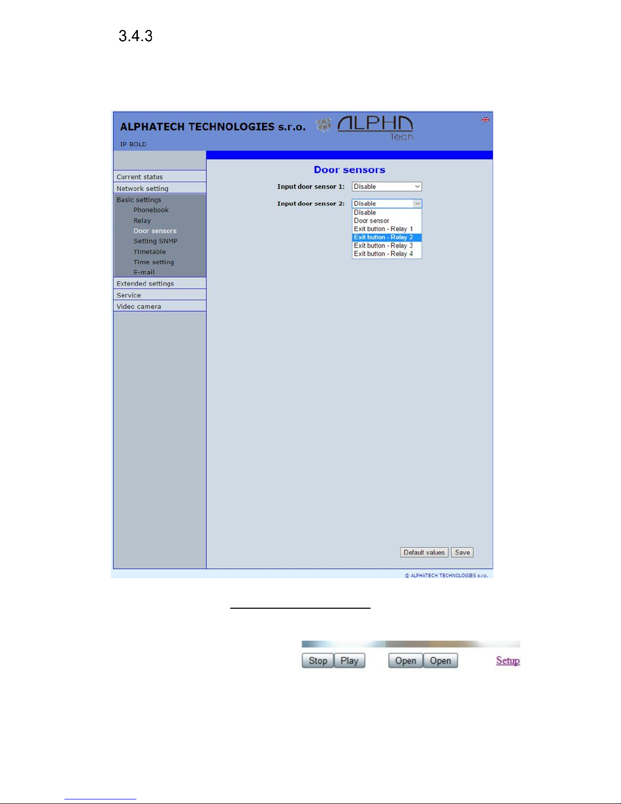
Door sensors
Door sensors are special functions of door entry IP Fermax which is
optional. It is HW option which is different according button number of each
model – inputs for door sensors. There is created information in the system about
close/open the door.
After performing of changes please don’t forget click on „Save“.
Input door sensor 1 / 2 Door sensor or disable – by permission is activated
transmission of Info about open / close the door. This Info is display
ether on this page – Now is – or on home page with video(under video
frame will be display
frames with this Info.
Further is transmitted to
programms UDVguard and iBell and as last is possible use it in SNMP.
Page 48
IP VarioBell - installation and operating instructions
48
Input door sensor 1 / 2 Exit button – relay 1-4 – because the use of door
sensors not found so wide usage, so these can be used as two inputs
to the function Exit button. When the input connections (short) so
activates the corresponding relay (switch monostabil) .
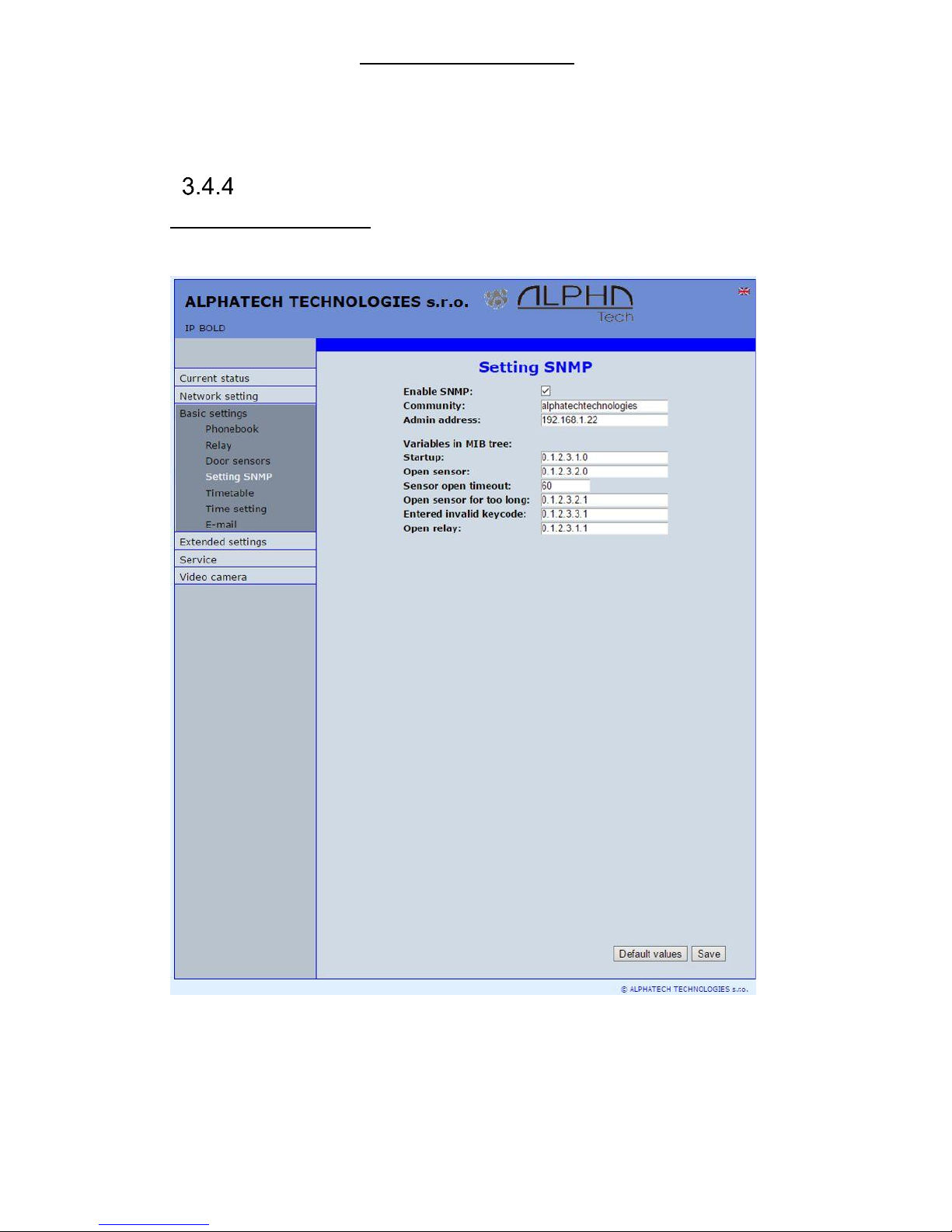
Setting SNMP
Remote management – SNMP is internet protokol designed for network
management. It allows progressive data collection for network management
purposes and its following evaluation.
After performing of changes please don’t forget click on „Save“.
Enable SNMP – by mark you activate remote management (SNMP)
Community – here is necessary select exact user of SNMP
Admin adress – setup IP adress or domain name of server where are sent
information according defined setting
Page 49

IP VarioBell - installation and operating instructions
49
Variables in MIB tree – is designed for identification of none sense numeral
chain OID OID is numeral identificator which definitely identify every
value in SNMP communication. OID is created by number sequence
separand by dot. Every dot represent exact level of tree structure into
which are OID maped. The numeral identification in range of each
undertree is not Unixe that is why OID is sent allways as whole unit.
Time profiles
After performing of changes please don’t forget click on „Save“.
In time profiles setting is available 10 profiles. Profile selection is perform
by click in top highlighted row – similiary as in phone book.
Timetable name – for easy orientation you can named every profile.
Period setting table – profile is active when current time match with setup
periods. Every day might have up to 3 active periods. Further is
Page 50
IP VarioBell - installation and operating instructions
50
possible deactivate whole day (first item on the row select „Active“ –
Yes /No) . In example on the picture it is Saturday or whole day setup
on active – in example i tis sunday. To use correctly this feature is
necessary to setup correct time in the unit (via Date and time setting)
Code for activation / deactivation– immediate switching status profile by using
DTMF. If you switch the time profile, then change it takes to meet the
closest in time profile changes (according to the times in the table) or
switch to another state using DTMF.
Active – display current profile status
Switch – by click you change profile status
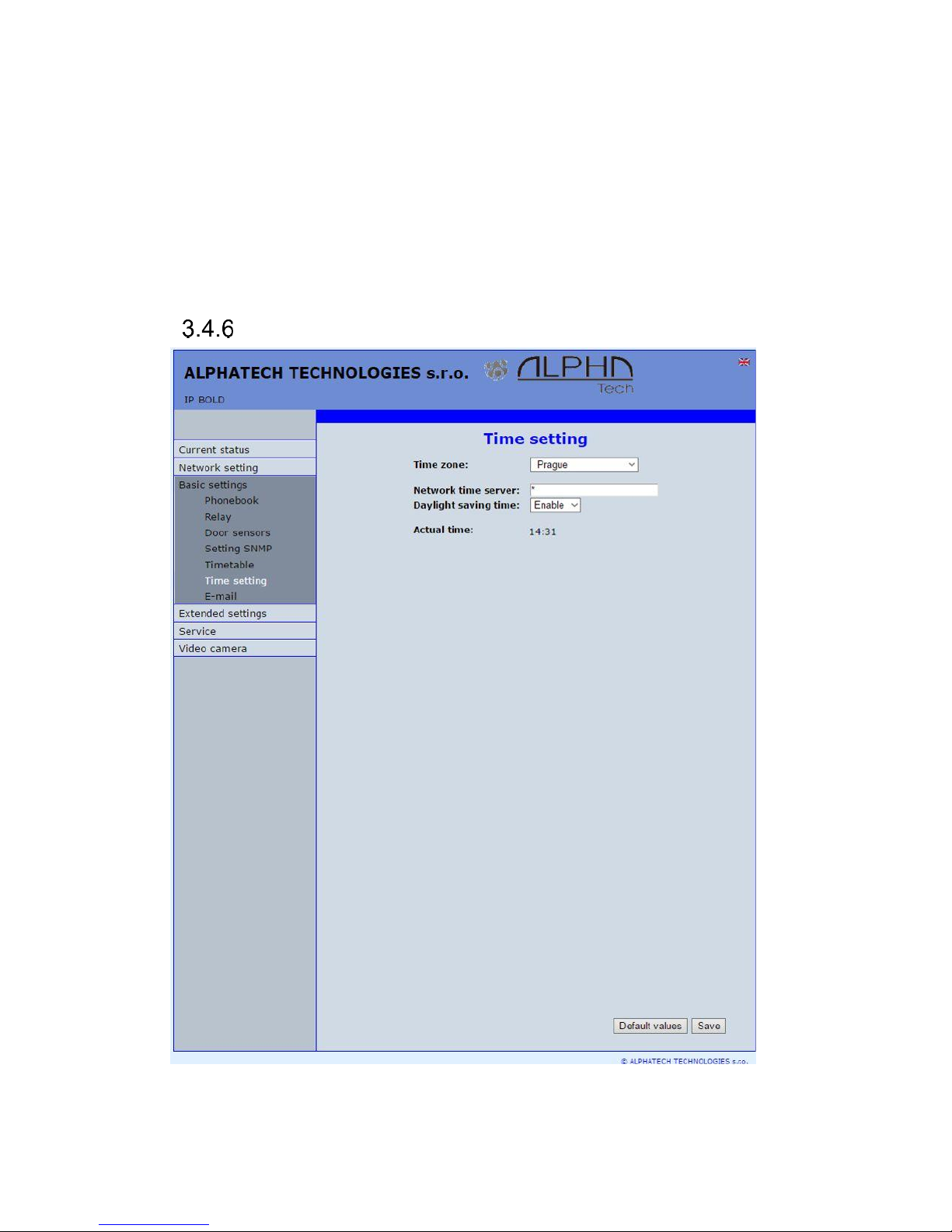
Date and time setting
After performing of changes please don’t forget click on „Save“.
Time zone – selection of installation time zone
Page 51

IP VarioBell - installation and operating instructions
51
Network time server – IP adress or domain name of NTP server. When you
dont know then by inserted * will IP Fermax find NTP server
automatically according own selection. Condition is setup in network
setting start gate and DNS.
Daylight saving time – permission to switch daylight time
Actual time– for control is display present time in IP Fermax
Page 52

IP VarioBell - installation and operating instructions
52
E-mail
When you want inform subscriber about missed calls from door entry you
can setup IP Fermax to sent out email after every missed call. You can setup
own subject and text of email. When you have door entry with camera you can
automatically add to email one or more pictures from camera. ( Pictures are
taken during ringing)
Door entry sends emails to all subscribers who have in phone book
preprogrammed valid email adress. When parametr E-mail in phone book is not
filled then emails are sent to preprogrammed default email adress.
After performing of changes please don’t forget click on „Save“.
Enable – it activates email sending
SMTP server (adress) - SMTP server adress where emails will be sent
Page 53

IP VarioBell - installation and operating instructions
53
SMTP port – adjust in case of none standard SMTP server setting only. SMTP
port is setup usually on value 25, but better is use port 587.
SMTP, there are three systems:
- Port 25 not allow encrypted - it is marked as obsolete, insufficient safety
- Port 465, not a domain hosting - is labeled as not recommended at
- Port 587, has no maladies previous two, is currently the only
recommended variant
SMTP account – when SMTP server requires authorization then must be in this
field mentioned name for registration to server. In opposite case leave
field empty.
SMTP password – password for registration to SMTP server.
Message from– sender e-mail mentioned in sent email.
Default message to – door entry send emails to adress mentioned in phone
book at appropriate subscriber. When you leave this field empty then
email is sent to default email which you setup in this field. When
receiver is not mentioned in phone book as same as default email field
the email is not sent. This e-mail is designed also for function control –
Send control message – when you want verify correct functionality of
emails sending then this control message is sent to this email.
Send timeout – Setup max time for which door entry try to deliver email to
inaccessible SMTP server
Attach pictures – enable send attachment with one or more Picture taken during
ringing.
Pictures count – setup Pictures number which will be attached to email.
Picture interval – setup time between each pictures
Message subject – setup subject of sending email message
Message body – enable correct contents of sending message. You can insert
to text special alternative symbols for user name, date and time for
door entry identification. Those alternative symbols will be substitute
by actual value before email sending. Via follow table of alternative
symbols:
$Device$ = door entry identification
$Date$ = current date
$Time$ = current time
$User$ = name of dialled subscriber
$DialNumber$ = dialled phone number
Send test message – when you want verify correct functionality of email sending
then control message will be sent to default email
Page 54

IP VarioBell - installation and operating instructions
54
Extended setting
This part is designed for system setting which are done once during installation
or when are problems with device kompatibility.
DoorPhone
After performing of changes please don’t forget click on „Save“.
Ringing timeout – time for which is ringing. When is setup more numbers as
same as progressive ringing then after this time ringing is ended on
first phone number (IP adress in P2P) and starts ringing on second. It
is time until which subscriber must pick up. When is not next number
to call then email is sent either to email adress mentioned in phone
book or to default email (E-mail setting).Setting range is 5 to 300sec
(6min.) caution: it might happen that ringing time will not be limited but
it is limited by time parametres of SIP protocol and it is usually 2-5min
Page 55

IP VarioBell - installation and operating instructions
55
(according SIP device setting). You can record message to SD card
during this time and simultaneously send email.
Maximum call duration – when call is picked up timer for call duration limit is
activated. When you insert empty, then there is no limit. The 10sec
before call end you hear tone after which you can dial character for
call prolongation and by this prolong the call about same time period.
Prolongation key – options are * or # and usage is descriped in „Maximal call
duration”
Ringing cycles count– this option enable repeating of call (or progressive call)
. In phone book is for example filled first and second phone number
and not create group. When come condition for first number: ringing time is out
- phone number is busy
- subscriber is not reachable / registrated in network
Then second number is dialled. When the same conditions come true
and ringing cycles are setup 2 the whole cycle is repeated one more
time.
Same key pressed again – when you press again the same button then you
setup door entry behaviour. Options are:
- call is hang up
- call is repeated
- nothing happen
Active button by HTTP – if checked, so is possible use http request for remote
activation button (like as press the button. This feature is for easy check
the installation IP Fermax.
Example:
http:// IPaddress /button_control?btn=1 - remote activate button 1
http:// IPaddress /button_control?btn=27 - remote activate button 27
Dialling timeout – this time concern buttons (keypad) and it is deciding for
correct code inserting. When space between button press is longer
than this time the cod eis not correctly evaluated . Situation:
- code keylock provides correct code evaluation
- number dial from keypad –dial end resolution
This time simultaneously prolong dial time at buttons which are initial
numbers of codes.
DTMF dialling timeout – this time concerns incoming calls from telephones and
it is deciding for correct code inserting . The principle is the same as
previous parametr but it concerns codes from telefone.
Keyboard mode – models TK only – memory number dial means that you
press 1-3 digit code on keypad which determined position in phone
book (1-999). The door entry process the call same way as you
pressed button on door entry (1-999). Direct phone numbers dial
means that you dial numbers by keypad as on ordinary phone.
Page 56

IP VarioBell - installation and operating instructions
56
When you have in numbers dial space longer than maximal number
inserting time then door entry calls. When you want in mode P2P call
to IP adress then „.” in IP adress is substitute by .
Camera light – wideangle camera has posibility of extra lighting when light
conditions are not acceptable. The lighting provils by white LEDs
(unfortunately infra LED cant be used but advantage is fully colour
picture). The door entry has dark sensor and you have following
options of lighting:
- OFF, LEDs will never light
- during conversation, LEDs are allways lighting during call
independently on surrounding light conditions
- in the night, LEDs are lighting according surrounding light
conditions independently on call
- during night call, Led svítí pouze při hovoru a podle okolního
osvětlení
Light intensity – here you setup LEDs light intensity
Labels light – name card might be backlighted by 3 ways:
- OFF, name cards will never be back lighted
- in the night , backlighting depends on surrounding light
- name card is permanently back lighted
Light intensity - here you setup backlight intensity
Daylight lower treshold – settings sensitivity ambient light sensor, the lower
limit of the window comparator (range 1-1021)
Daylight upper treshold - setting sensitivity ambient light sensor, the upper limit
of window comparator (range 1-1021)
ATTENTION The lower limit must always be less than the upper limit, as the
difference between the two values is the hysteresis (recommended to
maintain approximately 50)
IP Fermax
Počet rozšiřujících tlačítek – zde se zadává počet tlačítek rozšiřujících modulů.
Toto číslo je součet tlačítek připojených na základní modul. Základní modul má
vždy 2 tlačítka 1 a 2 (i když přední panel má např. pouze jedno tlačítko). První
rozšiřující modul začíná vždy tlačítkem 3. Pokud připojíte např. dva moduly
tlačítek po 10 tlačítkách, tak do tohoto pole zadáte 20. V telefonním seznamu se
vytvoří 22 položek, protože jsou 2 tlačítka na základním modulu + 20 = 22.
Klávesnice připojena – zde je nutno zaškrtnout v případě připojení klávesnice.
Nezáleží na pořadí modulu. Po zaškrtnutí se v telefonním seznamu vytvoří
maximum (999) položek pro využití adresování položek telefonního seznamu
z klávesnice.
Page 57

IP VarioBell - installation and operating instructions
57
Audio setting
After performing of changes please don’t forget click on „Save“.
Speaker volume + Microphone gain – amplification setting
ECHO limiter – it is designed for Echo cancellation which is created by distortion
of loud signal.During standard door entry call is working automatic
adaptive echo canceller which cancel the echo after cca 3 seconds of
talk and call is full duplex. The setting is : High intensity signals coming
from phone to speaker of door entry are distorted and automatic echo
canceller cant process them. This level of treshold you setup (in %).
How much should be reduced signal returning through microphone
input is adjusted by attenuation. Delay of returning signal is adjustable
by samples amount.
Tone – here you select acoustical signalling of different door entry status.
Options are: - None, this status will not be signalling
Page 58

IP VarioBell - installation and operating instructions
58
- default, simple signalling in default setting
- user, this is recorded signalling by user ( SD card) -via. Service
Volume – loudness signalling adjustment
Audio codecs
After performing of changes please don’t forget click on „Save“.
Priority – setting of codecs priority for usage. Some audio codecs requires
payable license (for example G729) – codec permission you perform
in Servis – license management.
Jitter compensation - jitter means fluctuation of packet delay during network
running
Page 59

IP VarioBell - installation and operating instructions
59
Video setting
After performing of changes please don’t forget click on „Save“.
Image size– image size selection. Stream H.263 knows just CIF resolution
(352x288) so bigger image is cut and smaller image is framed
Images per second – this setting concern mainly image transmission to WEB
browser. For H.263(4) is flow control flexibly according processor and
network workload and it is in range 5-15 pictures/sec. Maximal flow is
possible rejected by choice Low – Optimal – Full.
Further setting is standard image parametres petting and reset is immediatelly
visible in Windows screen.
Auto exposure - a choice between three balancing exposure image.
1. Manual mode – you set the exposure manually using the slider
Exposure at the bottom
Page 60

IP VarioBell - installation and operating instructions
60
2. Aperture priority mode – automatic exposure is adjusted by the
camera module
3. Software mode – exposure calculates and sets the software in IP
Fermax
Before adjusting image parameters, it is recommended to use the first
Default values..
Video watching (PopUp programm)
The door entry video records by USB WEB camera. The camera image
sends either like JPEG pictures set to WEB browser (first page on door entry IP
adress) or door entry sends stream video in coding H.263 and H.264. This
streaming video you can watch for example on IP phone with LCD display.
Further very popular video watching is using PopUp program iBell for
Windows. This program including user guide you can download for free on
www.alphatechtechnologies.cz . Except showing video has programm following
features:
- During call is automatically activated from Windows bar to front and show
image from door entry IP Fermax. When call is ended it is minimalized
again.
- Enable activate both door entry relays by click – door opening
- Enable acoustical connection with door entry IP Fermax – when door entry
calls to PC adress with installed and running programm then you can
receive call through sound card in PC. By click to DoorPhone button
in programm you can call to door entry IP Fermax – CAUTION PC sound
card ECHO canceller setting !!
- Programm might be installed to max.100 computers in network.
When is active door entry IP Fermax connection then all computers have
maximalized Windows with video from door entry. In programm you setup
door entry IP adress . Then you can operate more door entries in one
network. You assign setup „nameplate“ to appropriate door entry to
determine programms to door entries. The „nameplate“ is display in iBell
operates in P2P mode as same as SIP server registration ( SIP client) .
For Android operating system you can download programm UDVguard on
Google Play for free.
For iOS (Apple) operating system you can download programm UDVguard on
AppleStore for free.
Page 61

IP VarioBell - installation and operating instructions
61
Video codecs
After changes performing please don’t forget click on „Save“.
Priority – setting of codecs priority for usage .
Compatibility – Due some of VOIP phones producers specialities you have to
use in certain cases extra setting:
Yealink – phonesYealink
SNOM – it is script sending for showing JPEG video. It is unique
for SNOM phones
Page 62
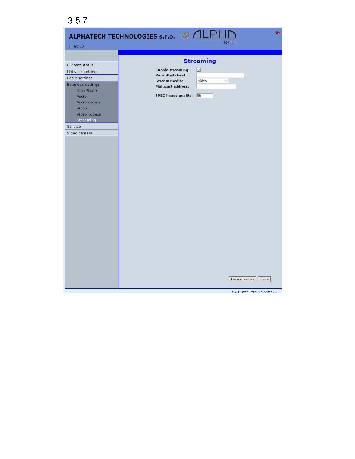
IP VarioBell - installation and operating instructions
62
Streaming
After changes performing please don’t forget click on „Save“.
Enable streaming – permitted / prohibited to provide video (H.263 and H264)
by door entry IP Fermax (server) protocol RTSP on port 554. To
receive such video you need some standard stream video players (IP
TV or for example Grandstream, MPlayer, VLC etc…). This video
running permanently. It is not depending on calls.
Permitted client – when is not filled up then video might be watch by anybody.
When is filled then video is limited just for this IP adress
Stream media – selection of what will be transmitted from RTSP server:
- video
- audio
- video and audio (now not implemented, we prepare)
Page 63

IP VarioBell - installation and operating instructions
63
Multicast adress – by inserting IP adress you permit sending RTP packets to
selected multicasting adress.
JPEG image quality – you insert percentage of video coding quality
Page 64

IP VarioBell - installation and operating instructions
64
Service
This part contents service functions.
Restart
By click on „Restart“ button you make door entry reset.
Page 65

IP VarioBell - installation and operating instructions
65
Configuration
The door entry IP Fermax allows saving of current setting to PC or other
repositury. From this saved file you can later restore this setting in a few levels
– for example phone book only. It helps for example during installation of door
entry in more entries to the building.
Save configuration – after click to „Make” button will be offered where you can
save the file
Load configuration – by click to empty button will be offered file selection.
Further is necessary select if phone book, network setting, SIP and
other parametres have to be loaded. By click to „Make” button is
loaded door entry petting from the file.
Default (factory) setting – is selectable in more levels:
Clear phone book – erase complete phone book into default (all 999
possible items)
Page 66
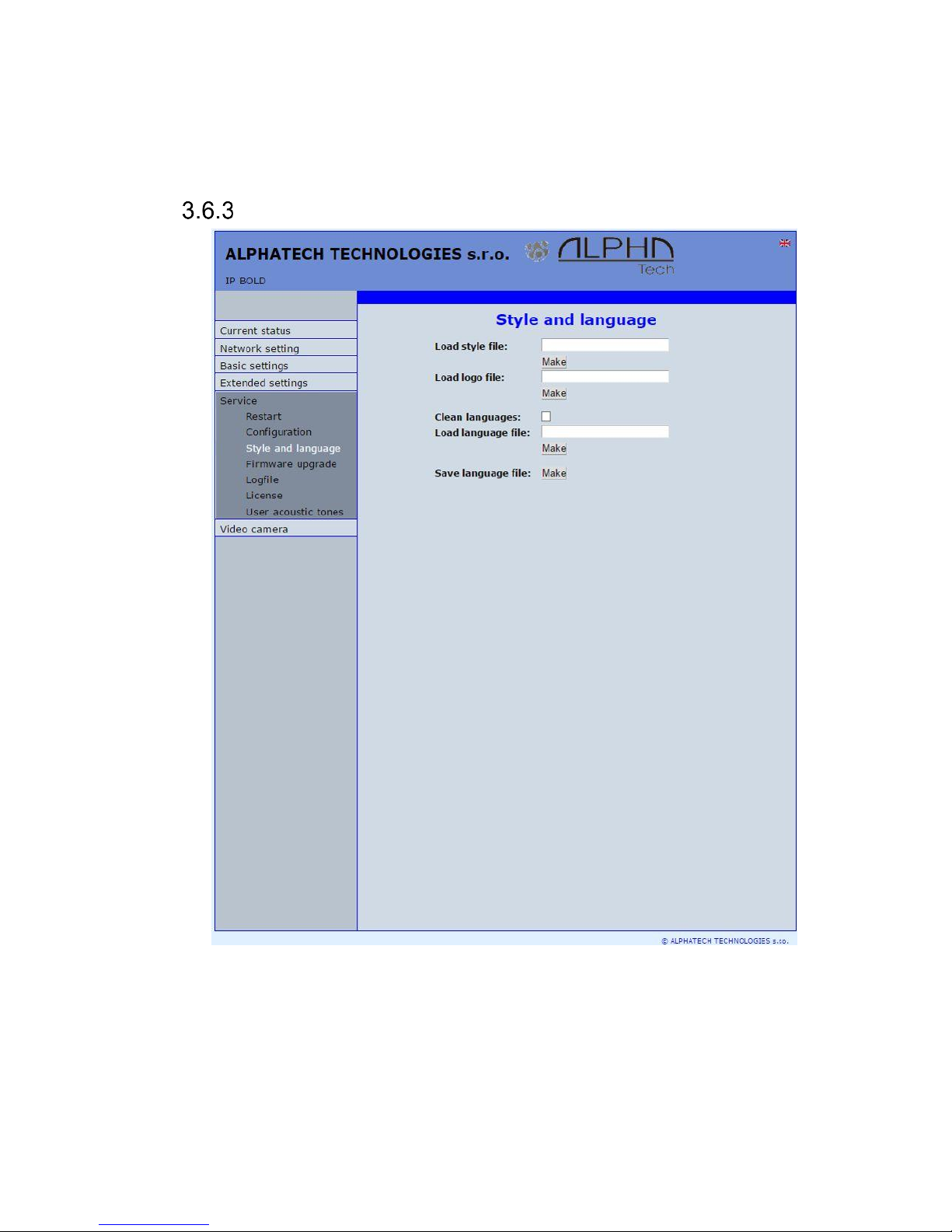
IP VarioBell - installation and operating instructions
66
Default network and SIP – make default setting of network (IP adress
192.168.1.250) and erase SIP setting
Default Others – all remains parametres put to factory setting
parametres.
Language and style
Load Style file – by click to empty button select the file and by click to „Make” is
style file (symbols and colours setting) loaded /*.html/.
File with customization use from firmware V3.4.2 on this place for change the
style (design) of WEB pages in doorphone IP Fermax /*.custom/.
Load logo file – by click to empty field select the file and by click to „Make” is
logo file. Logo file is standard picture /JPG or GIF or BMP or PNG/ with
dimension about 200 x 100 px and name logo.* .
Page 67

IP VarioBell - installation and operating instructions
67
Clean languages – it allows erase all added languages except factory
languages En+Cs (mark and click on perform)
Load language file – by click to empty button select the file and by click to
„Make” is new language file loaded.
Save language file – after click on „Make” button will be performed language
file export of just selected language
Style and language preparation
Style file is HTML file. WEBpage formating is included in this file.
Requirement is basic knowledge of HTML language. For transparent editing we
recommend use programm PSPad, symbols sada must be UTF8. Head of this
file must be : <!--VIPM Style 3--> . It is not possible use style files from other
door entry model.
LOGO – include to WEB page:
1. Prepare logo picture – dimension about 200px, name must be logo.*,
format is JPG,GIF,BMP,PNG, but GIF is recommended for usage
transparent logo (not frame) – for example logo.gif
2. Prepare HTML style file – for a reference style file please write to us a
request.
This is part of style file with logo include – red is required, green is
optional
…
</style>
<div class='container-div'>
<div class='header-div'>
<div class='header-sub'>
<h2>ALPHATECH TECHNOLOGIES s.r.o. <img src="/logo.gif"
align="center" width="190" height="55" alt="Alphatech Technologies
s.r.o."></h2>
IP-BOLD
<div class='header-right'>
INCLUDE_FLAG
</div>
Page 68

IP VarioBell - installation and operating instructions
68
To create new language we recommend following steps. Firstly make export of
language file (language version of exported file is simultaneously selected
language ( flag in right top corner). Rename this file to new language and open
in text editor (PSPad is recommended because file has rows ended by LF only
and no CR+LF as usual). Character set select UTF8 and make translation.
Translation: There is displayed a bit of the language file. Translates only the red
marked part (texts), the rest must be left unchanged, otherwise violates file
structure.
…
#sip parametry
SIP_TIT="SIP parameters"
SIP_MODE="SIP mode"
SIP_MODE_P2P="Peer-to-peer"
SIP_MODE_SRV="SIP server"
…
Save finished file (file name is language and no extension) and import to
door entry. The flag will be assigned to language file automatically according row
for example. SYS_FLAG="gb" for Great Britain.Country code examples (flag
codes) are mentioned in bellow table:
CZ
Czech republic
NL
Holand
GB
Great britain
IT
Italy
SK
Slovakia
DE
Germany
ES
Špain
PL
Poland
FR
France
HU
Hungary
GR
Greece
PT
Portugal
Further codes are according directive ISO-3166-1 alpha-2
Code examples of most often used languages:
Cs
czech
nl
Dutch
En
english
it
Italian
Sk
slovac
de
German
Es
spanish
pl
Polish
Fr
french
hu
hungarian
el
greek
pt
portuguese
Further language codes are according directive ISO 639-1
Page 69

IP VarioBell - installation and operating instructions
69
Firmware upgrade
Firmware version – display present firmware version in door entry IP Fermax
Choose firmware file – by click to empty field select file with firmware (for
example apt.firmware it is not file *.zip, but already unzip file – on website
are firmware files packed to archive *.zip)
In Windows is display proces so firmware upgrade. When from any reason
(power failure, network disconnection etc..) firmware upgrade is not finished then
you find backup WEB interface for repeating of firmware upgrade.
If you have any problem so is possible by switch of DIP 2 switch to position
on and restart on adress 192.168.1.250 you find backup WEB interface for
repeating of firmware upgrade. Name is admin and password is 1234. After, do
not forget move back DIP switch 2 to position OFF !.
.
Page 70
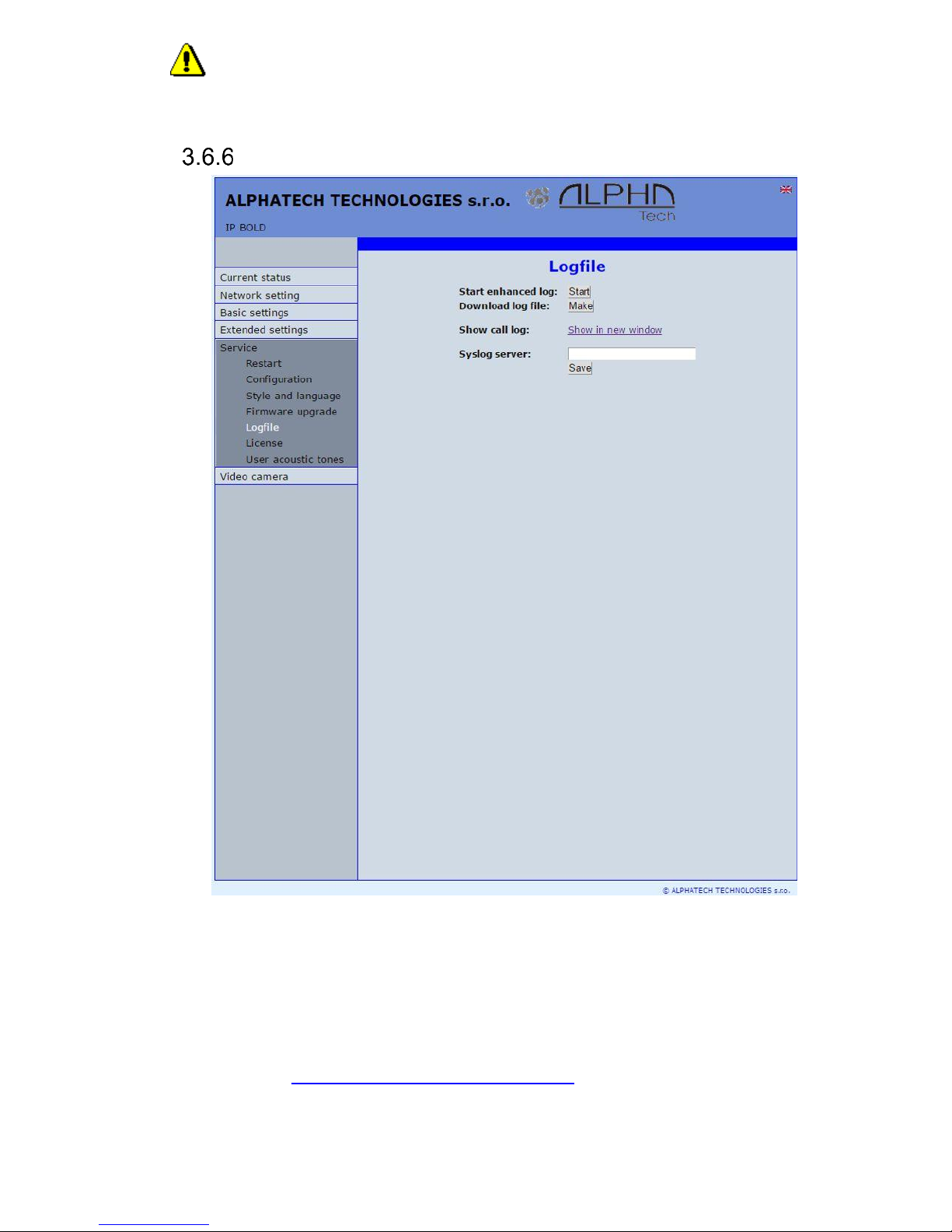
IP VarioBell - installation and operating instructions
70
After firmware upgrade you must make restart of doorphone IP
Fermax.
Logfile
Start enhanced log – it is OFF in default to save processor efficiency. When
you switch it ON then are save into internal memory detail information
about door entry operation. It is very helpfull to solve different problems
( compatibility etc..).
Download log file – after activation of enhanced log perform action which
doesnt work correctly and immediatelly after performing click on button
„Make”. You save like this record of extended log file into file which you
send to www.alphatechtechnologies.cz for further analyses (see
procedure. below).
Page 71

IP VarioBell - installation and operating instructions
71
Show call log - in new WEB interface window are online display information
about making calls.
Syslog server – IP adress or server name of syslog server where will be sent
records about IP Fermax door entry operation (do not forget setup NTP
server for setting of internal door entry clocks otherwise records will be
saved with incorrect date and time)
The procedure to download Enhanced LOG file. Really send by e-mail
LOG downloaded file, do not send copies of screens, videos, etc.
1. Turn on enhanced LOG (click Start). Before this step, it is recommended
to restart the IP Fermax
2. Perform the action that you are interested in, where you have the
problem
3. Immediately download the LOG file uploaded to your PC
4. This file be attached to e-mail a brief description of the problem and send
(email contacts on www.alphatechtechnologies.cz)
Page 72
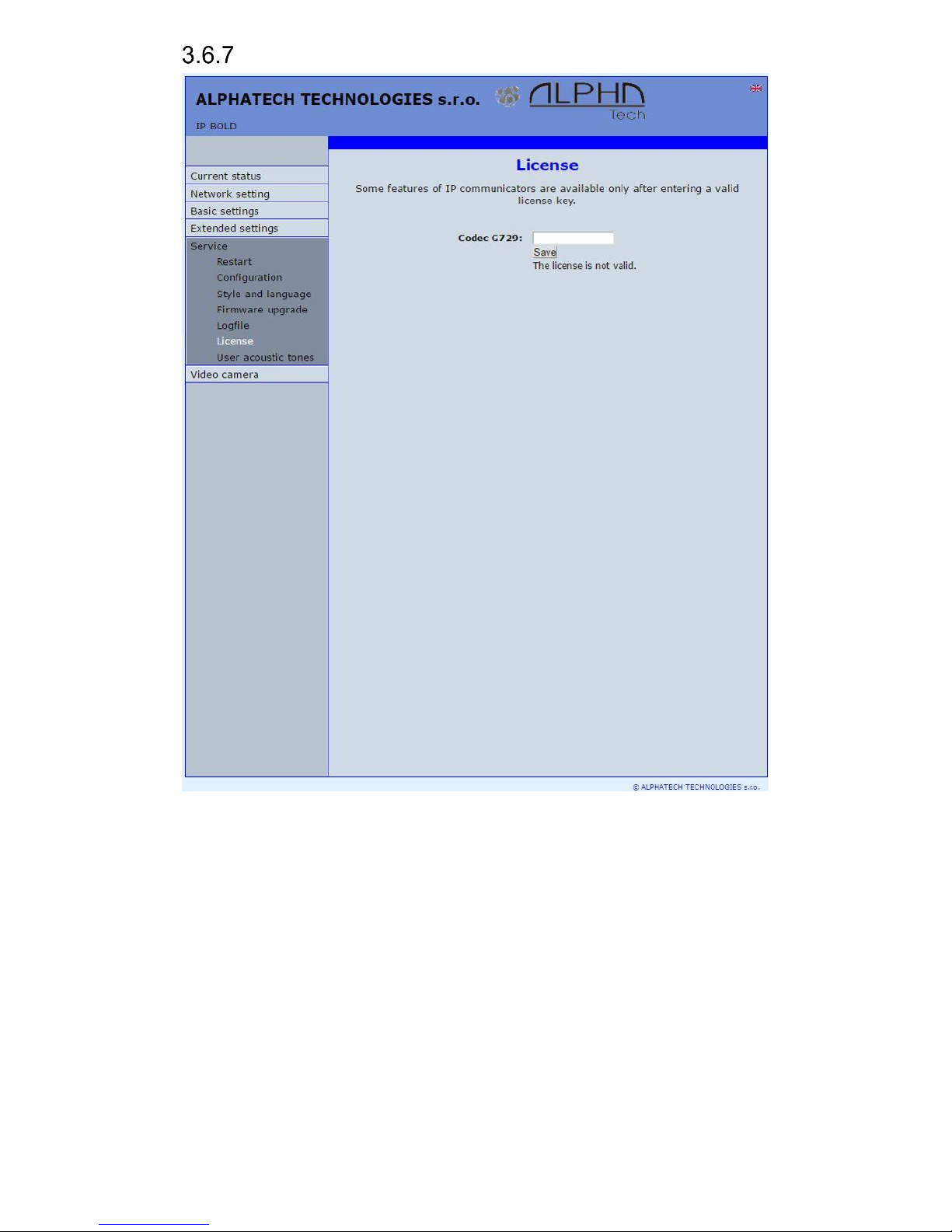
IP VarioBell - installation and operating instructions
72
License
This page allows extend door entry features about payable functions via
licenses.For example audio codec G729.
After payment you receive license number by email
License validity shows if license is working correctly. The license code is
connected to MAC number of door entry.
Page 73

IP VarioBell - installation and operating instructions
73
Sound files
This page is designed for recording own (user) sounds signalling. By click on
„Play“ will be played currently active sound file (selection is permormed on page
„Audio setting“ eventually sound of relay closing on page „Relays“).
Attention files are recorded on a microSD card!
Audio files: WAV – 8Kbit – mono – 16bit PCM
Page 74
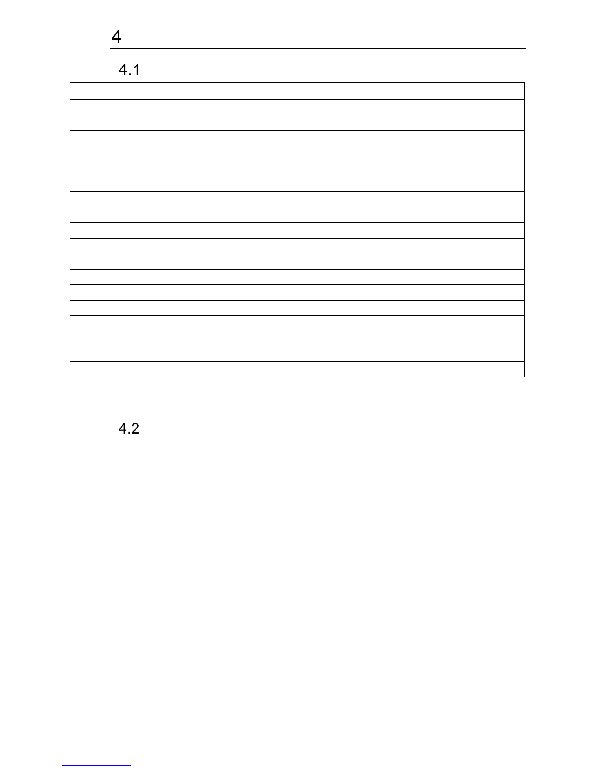
IP VarioBell - installation and operating instructions
74
Technical parametres
Electrical parametres
Parametr
Value
conditions
Interface
Ethernet 10BaseT, 100BaseTx
VoIP protocol
SIP 2.0 defined RFC3261
Default IP address
192.168.1.250
Audio
G.711u, G.711a, G.726-32b, GSM, G722,
G729 (optional)
Band range
300Hz – 3400 Hz
Echo supression
Automatical
Output power
Class D, 1W/8ohm, 94dB/1kHz/1m/1%
Video
série JPEG, MJPG, stream H.263, H.264
Resolution
Max. 640 x 480
Camera angle
120deg H x 110deg. V
Power supply - adapter
12VDC ± 2V , 12VAC ± 1V
- or PoE
IEEE802.3af Altern. A + B
Max. consumption
300mA
12Vss
Max. switching voltage by
relays
48V
when I < 1A
Max. switching current by relays
2A
when U < 30 V
Temperature range
- 20 to + 80°C
Mechanical dimensions
- Fermax -
Page 75

Video parametres
Video formats: JPG, MJPG, H.263, H.264
Video for WEB:
Internet Explorer, Mozilla, Opera, Firefox… - (set of JPG pictures - Port 80)
it is used repeated http request „IPaddress/video.jpg“
programm PopUp (UDVguard) - (MJPEG stream - Port 80) is used http
request „IPaddress/video.mjpg“ (sometimes is reload necessary to run).This
video is more fluent and has less network strain.
Stream video for IP phones:
H.263 and H264 is established by IP Fermax door entry and IPvideo phone
over SIP/SDP protocol on standard SIP port. The video (as same as sound)
then runs by RTP protokol on ports agreed over SIP (usually 9078).
rtsp request „rtsp://IPaddress/video.264“
or rtsp request „rtsp://IPaddress/video.263“
Video parametres:
JPG Pictures are created in IP modul and for all transmit protocols are the
same .The Size (resolution) of video is selected in "Video setting" on WEB.
Maximal resolution is defined by USB camera type and mostly is 640x480
Stream H.263 knows CIF resolution (352x288). It means bigger JPEG is cut
and smaller framed.
Frequency (1-15 picture./sec) JPG Picture is selected in "Video setting" on
WEB as Low – Optimal - Full.
Frequency MJPG and Stream H.263 coming from camera. It is used every
second and reset is between 7-15 pictures/sec. Higher resolution brings
decreasement of Pictures/ sec. (limited by processor efficiency)
Ports:
Port 80 for http (WEB pages even JPG / MJPG video on them)
Port 5060 for SIP
Ports RTP with oposite party communicates over SIP. Usually Port 7078
suggested for audio and Port 9078 for video
Port 554 video( H264 and H263) provided by door entry (server) protocol RTSP
Audio files: WAV – 8Kbit – mono – 16bit PCM
Setup: Default IP adress 192.168.1.250
name: admin / password: 1234
Video: name: video / password: 1234 (if required).
Page 76

Requests
VIDEO:
JPG - http:// IPaddress /video.jpg
MJPG - http:// IPaddress /video.mjpg
H.263 - rtsp:// IPaddress /video.263
H.264 - rtsp:// IPaddress /video.264
RELAYs:
http:// IPaddress /relay_control?1=on
http:// IPaddress /relay_control?1=off
http:// IPaddress /relay_control?2=on
http:// IPaddress /relay_control?2=off
http:// IPaddress /relay_control?3=on
http:// IPaddress /relay_control?3=off
http:// IPaddress /relay_control?4=on
http:// IPaddress /relay_control?4=off
BUTTONs:
http:// IPaddress /button_control?btn=1 - remote activate btn 1
http:// IPaddress /button_control?btn=27 - remote activate btn 27
Page 77

Page 78

Guarantee conditions:
The product was shop-checked. The producer guarantees that this product will
keep the features described in these operating instructions in the course of
guarantee provided that the user will be handled with it as described in the
operating manual. Particularly the warranty does not cover damage from
improper intervention via Telnet. The guarantee will be extended by period of
possible guarantee repair.
When claiming in guarantee period please contact your dealer. The producer
only will make the guarantee repairs. Attach the description of claim reason,
proof of purchase and your exact address to the product.
The guarantee does not include:
• mechanical, thermal, chemical and other damages caused by user’s
activities
• defects caused by natural disasters
• defects caused by repair or changes carried out by user or other
unauthorized person
• willful damage of product
• incorrect use of product caused by other use than specified in operating
manual (e.g. installation, programming, improper use of Telnet)
• damages caused during product transport to customer and from supplier
Producer:
Dealer:
Date of sale:
Page 79

© Alphatech Technologies s.r.o. 2014-2016 version V3.5
 Loading...