

Page 1

iLoft Duox Telephone
INSTALLATION AND PROGRAMMING MANUAL
INSTALLATION AND PROGRAMMING MANUAL
Page 2

CONGRATULATIONS ON PURCHASING THIS QUALITY PRODUCT!
Fermax Electronica manufactures and develops top class equipment which fulfi l the highest
design and technology standards.
Your FERMAX telephone will allow you to communicate with the entry panel and open the
front door if you wish.
We hope you enjoy its range of functions.
www.fermax.com.
Technical publication of an informative nature published by FERMAX ELECTRONICA.
As part of its constant improvement policy, FERMAX ELECTRONICA reserves the right to
modify the content of this document and the characteristics of the products referred to in it at
any time and without prior notice.
Any modifi cation will be refl ected in subsequent editions of this document.
This product is protected with the following patents and utility models:
PATENTS: US 9215410, US 9762852, BE1023440, AU2014203706.
UTILITY MODELS: ES1187384U, ES1141495U, FR3038192, DE202016000632U1,
CN205987229(U).
Cod. 970113I V10_18
Page 2
Page 3

INDEX
iLOFT DUOX TELEPHONE 4
Installation 4
Connections 5
Diagrams 5
Description 7
- Buttons 7
- Leds 8
Available Functions 9
Capacities 9
Technical Characteristics 10
Programming the telephone 10
- a) From the Panel 11
- b) From the doorbell 12
Telephone set tings 13
- Selecting ringtones 13
*From Panel 13
*From Guard Unit 13
- Simplex conversation mode (Push to Talk) 14
- Call Volume Controller 15
Resetting Parameters 16
Operating 17
* Answering a call 17
· Activating audio 17
· Hanging up 17
· Auto-start 17
*Opening the door 19
· In conversation 19
· Upon receiving a call 19
* Audio volume controller cancelling ringtone 19
* Call to Guard Unit 19
F1 (Additional Functions)
20
Page 3
Page 4
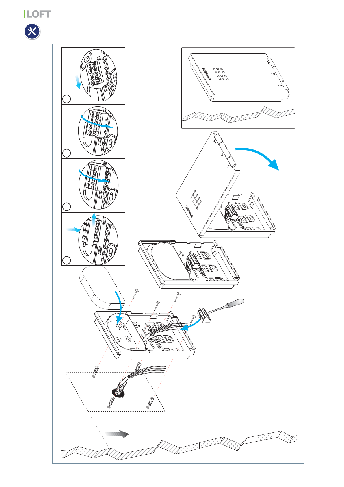
TELEPHONE installation
1.60m
5.25 feet
(*)
(*)
1 2 3 4
Page 4
Page 5
CONNECTIONS:
T
+
A
-F1
B
in
B
in
B
out
B
out
T
+
A
-F1
B
in
B
in
B
out
B
out
T
+
A
-F1
B
in
B
in
B
out
B
out
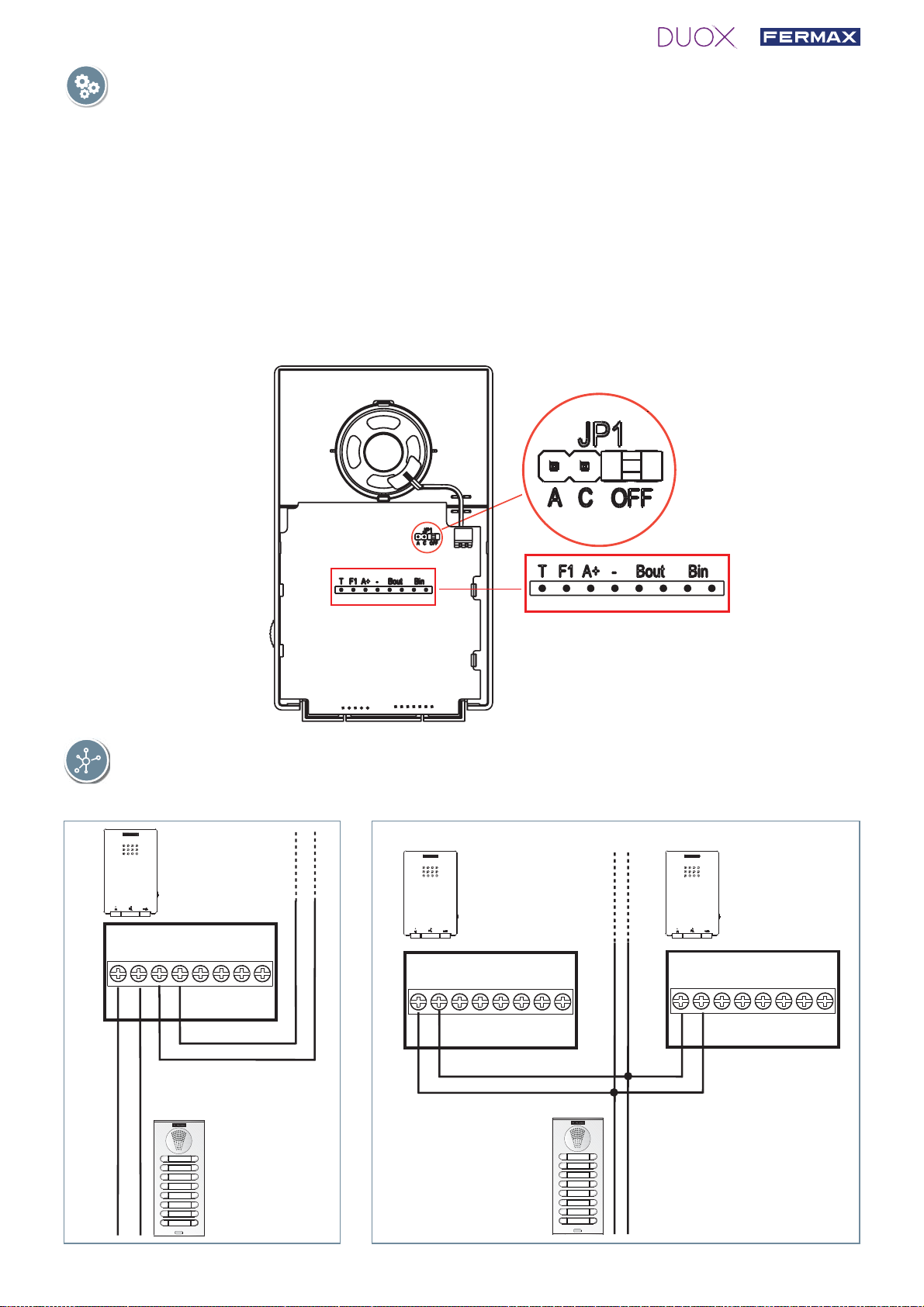
Connection Terminals:
B, B : DUOX Bus: Power, data and audio.
T, -: Connection House entrance "door bell." (P1).
A, -: Call extension connection or light and bell activator
F1: Button for additional functions. It provides a negative upon being activated.
JP1: Line adaptation bridge:
• Right: Without line adaptation.
• Centre: Type C adaptation.
• Left: Type A adaptation.
DIAGRAMS
Wiring: 2 non-polarised wires.
Page 5
Page 6
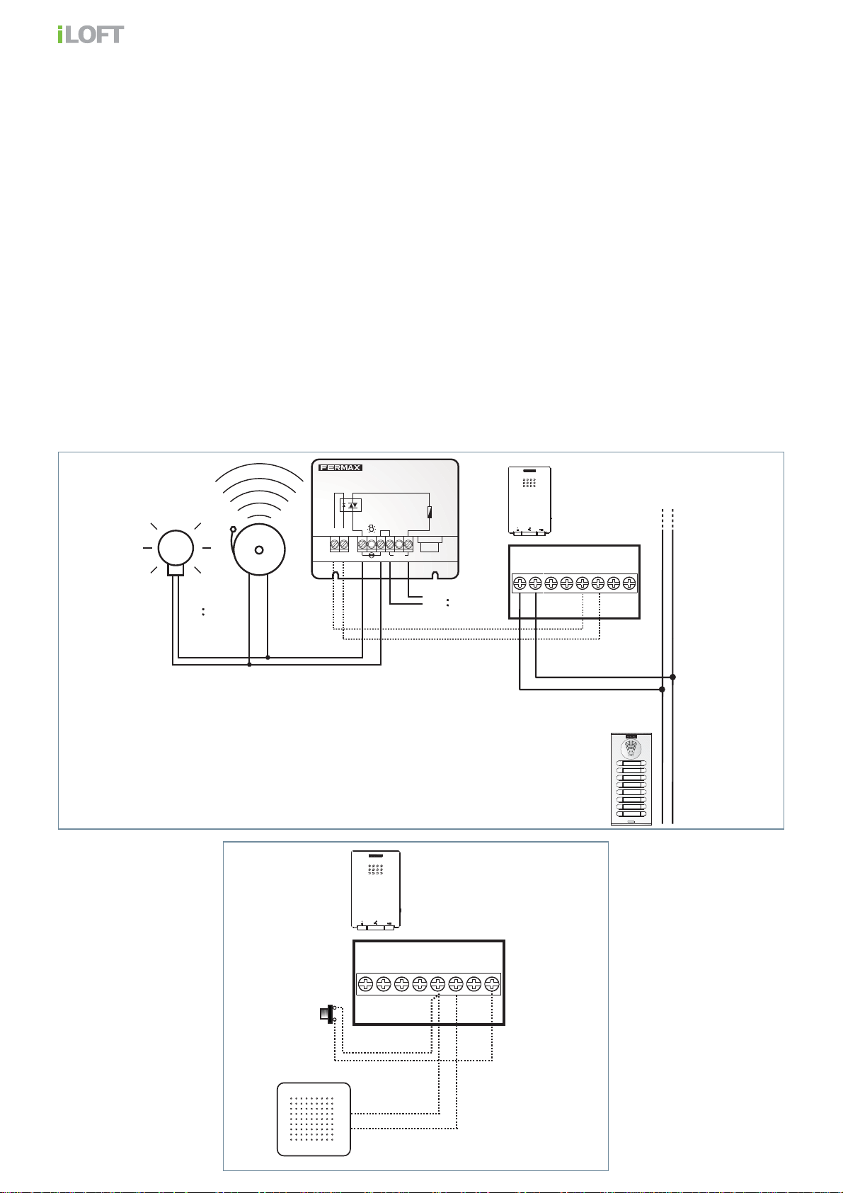
P1 (T, -): You can place an external button to make a call to the "Door bell" (this bell would
-A+A
Red
F1 2A
2A.
Max. 2A
+A -A
110-240Vac
50-60Hz
REF. 2438
ADS LIGHT COMMANDER
ACTIVADOR DE LUCES ADS
110-240Vac
110-240Vac
T
+
A
-F1
B
in
B
in
B
out
B
out
replace the ding-dong of the home entrance).
Notes:
- The doorbell can not be changed and is different from those selected for entry panels or
guard unit.
- The do not disturb function silences this tone.
- You can program the phone’s address with this button. See chapter: Programming the
phones address via the doorbell.
A, -: The phone has these terminals, to which you can connect a call extender ref. 2040
or a light and doorbell activator ref. 2438, which are activated when a call is received
or from a outdoor panel, guard unit or from the home’s frontdoor.
Note: If the call disconnection (do not disturb mode), is activated, the terminal will continue
working. Through this, the same tone sounds as that confi gured for the call answering tone
from the panel, guard unit or doorbell.
Page 6
P1
+
A
-F1
out
out
B
B
in
in
B
B
Call extension
T
Page 7
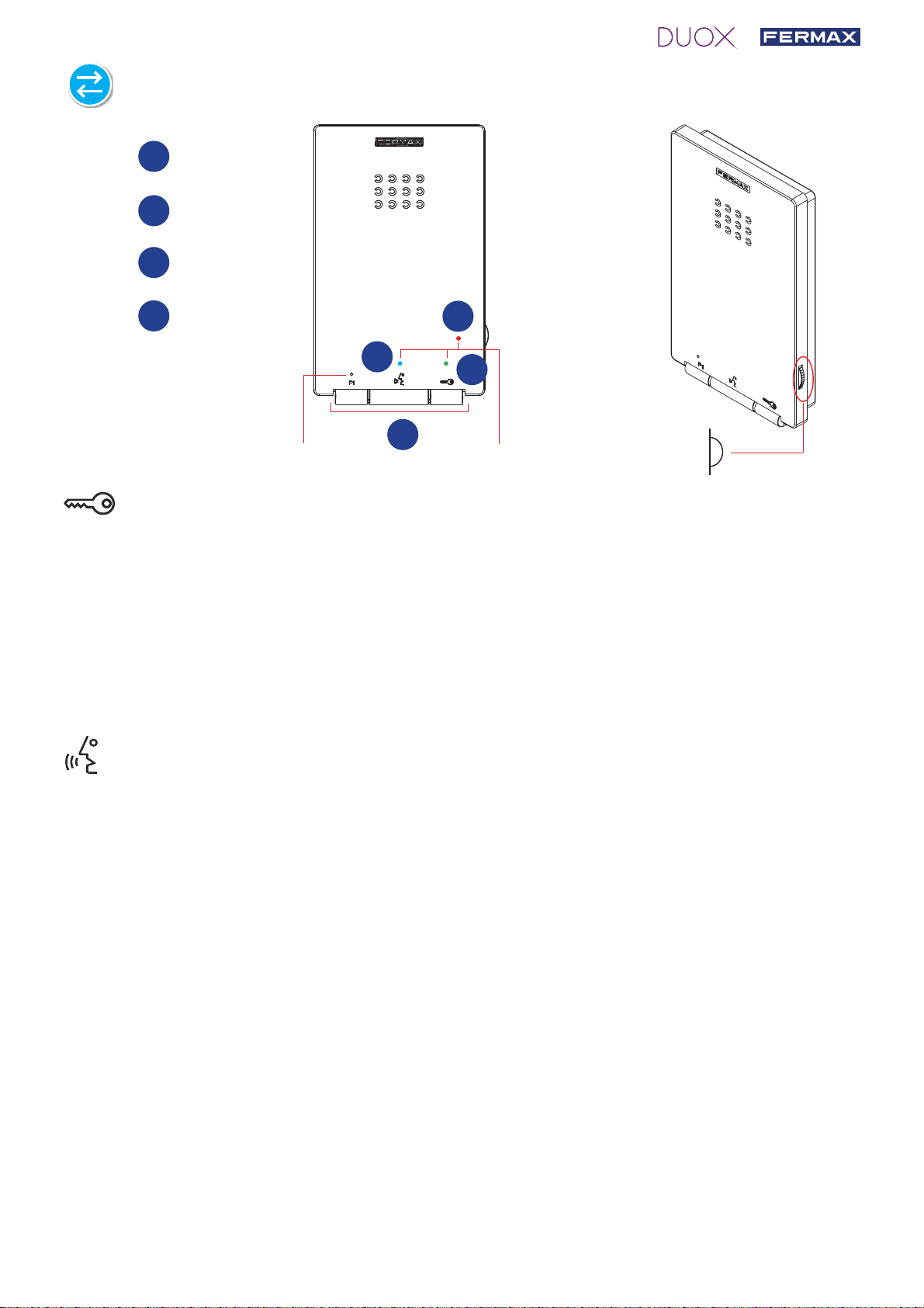
iLOFT DUOX TELEPHONE DESCRIPTION
1
Red LED
Green LED
2
Blue LED
3
4
Buttons
1
Buttons
3
2
4
Micro
Door open / guard unit call button (function available depending on type of installation).
· While in conversation with the Outdoor Panel (audio activated), pressing it will
activate the open door lock-release.
· Upon receiving a call (audio not activated). If the phone is not answered you have
30 seconds to open the door.
· When you press this button with the telephone hung-up (standby) a call will be
made to the guard unit (where one exists).
Audio activation, hang up and auto-start button.
On receiving a call the user has 30 seconds to answer. (The red led fl ashes during
this time to indicate a pending call).
Leds
Potentiometer
· Audio activation: When a call is received, press this button to speak to the visitor.
The audio channel is opened from the panel entrance to residence, (the blue led
lights up indicating a conversation with the panel entrance, and everything said
will be heard by it).
· Hang-Up: Press to terminate communication. (When fi nished the blue led light again
turns off and the red light is turned on).
The conversation is limited to 90".
The conversation is private, no other terminal can hear it.
· Auto-start (panel 0 in the same block): In standby, press and release this button
(the blue led lights up). If the panel or channel is busy, you will hear a busy tone
and return to standby.
Auto-start: Only with video outdoor panel.
Notes:
- "Hands free" mode is default mode.
- While the audio channel is open the input audio can be regulated with the potentiometer, without affecting the call volume. The selected setting will not be altered if the call volume is subsequently adjusted.
Page 7
Page 8
- If the telephone is confi gured in “simplex mode”, (press to speak and release to listen), the audio chan-
nel will be activated to hear sound at street level.
- If making a call from the 0 panel to another home, during the 30 second wait for the home to answer,
auto-start with the 0 panel will not be possible. If the line is busy or there is another busy telephone in
the same home either.
- During the conversation “hands free” can be adjusted to “simplex mode”.
- If there are various telephones in the same home, the audio will only come from the fi rst one picked-up,
leaving the remaining phones in standby.
Auxiliary F1 function.
F1 confi gured as exit:
· It is initially confi gured, by default, as an exit and sends a negative.
Note:
- From the telephone you can activate an auxiliary relay connected to a F1 terminal for an extra function
such as the landing light, alarm activation, etc.
- When you press the F1 button the telephone generates a beep and via the bus transmits a command
to activate a Duox relay (if installed). Simultaneously the F1 terminal provides a negative, as the button is pressed.
Leds
Red LED:
On. Programmed telephone (standby)
RAPID blinking. Telephone not programmed (standby).
SLOW blinking. Indicates that the do not disturb function is activated.
Blue Led:
On. Conversation in hands free audio model.
On/Blinking. Conversation in simplex audio mode
Green LED: According to confi guration.
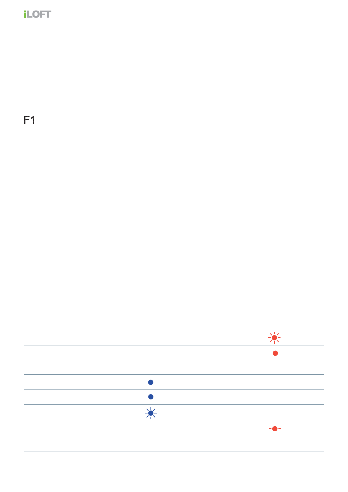
LED FUNCTIONS BLUE led GREEN led RED led
Not programmed
Standby
Call/Called
Handsfree audio
Output Audio (simplex mode)
Input Audio (simplex mode)
Do not Disturb
Doormatic
Page 8
(depending on confi guration)
Page 9

AVAILABLE FUNCTIONS
The functions available on the telephone are summarised in the following list:
· Guard Unit Call
· Opening the door
· Call to Guard Unit.
· Ringtone selection.
· Programming from panel and door bell
· Audio connection upon picking up
· Volume regulation
· Auxiliary F1 function.
· Doorbell
· Light and Doorbell Activation
· Hands free audio mode / "simplex (Push to talk)"
· DOORMATIC (depending on confi guration)
CAPACITIES
· Number of terminals per home: maximum 3. Properly size consumption of the power source.
· Number of terminal addresses per sub-block:
· Number of terminal addresses per block: 9999.
·Number of blocks: 99.
·Address for each telephone: 6 decimal digits: 000000. 999999. The address 000000 is the
default address and the telephone does not work.
· Number of conversation channels: 2 per BUS (If there is only audio amplifi ers in the instal-
lation).
· Wiring: 2 non-polarised wires, depending on the wire, distances and terminal charges are
stipulated.
· Number of different optional ringtones: 5.
· Call Volume Regulation.
· Input and output audio volume regulation.
· Maximum conversation time. 90 seconds
99.
· Maximum time to pick up on receiving the call: 30 seconds
· Maximum time to programme the telephone: 2.5 minutes.
Page 9
Page 10

TECHNICAL FEATURES
146mm
Telephone Dimensions (Height x Width x Depth*.):
146 x 90 x 20 mm
Notes:
- this telephone can be installed directly at surface level,
to the wall or in a standard fl ush mounted box.
standard box.
- XX :
90mm
20mm
IP: 30 / IK: 04
Power supply (non-polarised)
Consumption (±5%)
in standby + led
maximum
Maximum number of terminals per residence
Telephone address: 6 decimal digits
Operating Temperature
Call Ring tone Selection
Number of conversation channels: 2 per BUS
PROGRAMMING THE iLOFT DUOX TELEPHONE
18 Vdc
18 mA
210 mA
3
000001...999999
-5º, +40ºC
There are two options to program the phone:
a) From the Panel.
b) From the Doorbell.
Notes:
- The telephone will not function until it has been programmed.
You can see that the telephone does not have a programmed address because the led blinks. Once
the telephone’s address is programmed it is indicated via a fi xed red light.
- Programming is always done from the panel activated as the master panel. Confi guring as master
panel Press the SW1 button 3 consecutive times quickly. After 2 seconds, a confi rmation tone is
heard, and the master panel is activated. Once having completed the monitor’s programming, deactivate the MASTER panel by pressing the SW1 button 3 consecutive times. Y ou can also confi gure
it via a code on the keypad. For more information see the DUOX Panel Settings at www.fermax.es.
- The programming from the Doorbell is only available if the telephone has not been previously
programmed, that is, if no address is recorded.
- If there is a guard unit, it must be in night mode.
Page 10
Page 11

a) Programming a telephone address from the entry panel
5"
¸
BEEP
With the telephone connected and hung-up:
1. The user should start in the "Ringtone
Selection" confi guration menu.
outdoor panel
ton for 5 seconds until you hear a "beep"
then release, a ringtone will sound on the
current panel. While in this mode:
Note:
Telephone not yet programmed, red LED
blinks quickly.
from the
“. Press and hold the but-
5"
+
¸
BEEP
2. Press the F1 and the
neously for 5 seconds until you hear a tone
(BEEP). Release.
Note: Optional: pick up the telephone to establish
communication with the entry panel to indicate which
residence you are in.
3. Press the button/residential call code from
the panel. A confi rmation tone will sound
on the telephone. The telephone is programmed, (red led off)
button simulta-
Note: The time from which you hear the confi rmation
beep for entering in telephone programming,and the
call is made from the panel to program the phone’s
address must be less than 2 and half minutes.
Page 11
Page 12

T
+
A
-F1
B
in
B
in
B
out
B
out
5"
¸
T
+
A
-F1
B
in
B
in
B
out
B
out
b) Programming the phones address via the doorbell.
Note: Only if the phone has not been previously programmed, that is, if no address has been saved.
Telephone not yet programmed, red LED blinks.
With the telephone connected and hung-up:
1. Press the door bell or short terminals "T"
and "-".
Upon performing this operation you hear
a doorbell.
Doorbell
2. After 5 seconds short or maintaining the
door bell pressed, the entering programming tone sounds.
After this moment you can stop shorting or
pressing the door bell. While in this mode:
Doorbell
Note: Optional: pick up the telephone to establish
communication with the entry panel to indicate which
residence you are in.
3. Press the button/residential call code from
the panel. A confi rmation tone will sound
on the telephone. The telephone is programmed, (red led off)
Note: The time from which you hear the con fi rmation
beep for entering in telephone programming, and the
call is made from the panel to program the phone’s
address, must be less than 2 and half minutes.
Page 12
Page 13

iLOFT DUOX TELEPHONE SETTINGS
5"
¸
BEEP
Ringtone Selection.
The telephone allows you to select different ringtones for calls from the entry panels and
calls made from guard unit.
Accessing "Ringtone Selection" Mode
We can select from 5 ringtones.
1. From the panel: With the telephone in standby and hung-up:
1. Press and hold the
ringtone will sound on the current panel.
2. Press the F1 button to select the ringtone, (circular sequence), the last one played
will be the one selected.
2. From Guard Unit: Being in "ringtone selection from the panel" mode:
button for 5 seconds until you hear a "beep" then release, a
3. Press the
the current guard unit ringtone.
4. Press the F1 button to select the ringtone, (circular sequence), the last one played
will be the one selected.
button to select "confi gure the ringtone from guard unit", you will hear
Page 13
Page 14

BEEP
+
BEEP
BEEP
Exit ringtone selection (standby):
5. When in the "selecting ringtone from guard unit" if you short
press the
button you will hear a double beep and you
will exit the menu and return to standby.
Note: The last ringtone produced in each menu is saved.
Notes:
- You can also exit the guard unit ringtone menu from the panel, after
inactivity for 10 seconds (storing the last ringtone played). The exit is
confi rmed with a single beep.
- You can also exit the guard unit ringtone menu from reception, after
inactivity for 10 seconds (storing the last ringtone played). The exit is
confi rmed with a double beep.
¸
10"
Simplex (Push to Talk) conversation mode
Default conversation mode on the telephone is "handsfree"
During a "handsfree" conversation, you can reset to simplex conversation mode (press the
button to speak and release to listen).
1. Starting from a handsfree conversation: press the F1 button and
simultaneously until
you hear a "BEEP" and see the blue led fl ashing intermittently, while input audio remains
active (you can hear the panel on the telephone).
Page 14
Conversation
Hands Free
Audio channel
Entry Panel - Residence
Page 15

2. From this point every time you press the
button, the output audio channel will activate
(you will hear the telephone on the panel) and
a constant blue led will light up.
audio channel
Residence -> Entry Panel
BEEP BEEP
audio channel
Entry Panel -> Residence
On releasing the button the input
audio
channel will activate (you will hear the panel
on the telephone) and the intermittent blue led
will light up.
Once you enter “simplex mode” it will remain
activated by default. The next time the audio is
connected, the input channel will activate when
you press the
button (short press).
3. To re-establish "handsfree" conversation mode
once the audio channel is open, press F1 and
the
BEEP BEEP,
button simultaneously until you hear a
(a fi xed blue light)
+
Active audio
Call Volume Regulation
The telephone allows for call ringtone volume regulation and the output audio volume.
Starting from standby mode, use the controller to adjust the call volume to any setting
between the maximum and minimum levels.
Setting the call volume to minimum provokes the disconnection orDo not disturb mode.
this mode the led remains fl ashing. T o reactivate the ringtone, you must move the controller
above the minimum level.
With the telephone in conversation mode you can slide the controller to change the input
audio volume to one of the 8 possible levels. In this case the volume level of the ringtone
does not change.
In
Page 15
Page 16

Disconnecting a call:
5"
¸
BEEP
Do not disturb mode
LED
POTENTIOMETER
Notes:
- Regulation affects all ringtones generated by the telephone: outdoor panels and entrance doorbells.
- To hear the selected setting you can:
· make a call from the entry panel.
· enter ringtone selection mode.
- Call volume regulation does not affect the incoming audio settings.
- If during call volume regulation the potentiometer is turned down to its minimum level, a red led blinks
indicating that the call has been disconnected (Do not disturb mode).
-The disconnection affects all ringtones generated by the telephone.
- If you want to disconnect the call, the call extension sounds or the lights and bell activator is activated.
This terminal is not affected. Through this, the same tone sounds as that confi gured for the call answering
tone from the panel, guard unit or doorbell.
Resetting Parameters
The installer reset sets ALL telephone values to default.
Note: If there is a guard unit, it must be in night mode.
With the telephone connected and hung-up:
1. The user should start from the "Ringtone
Selection" confi guration menu. Press and
hold the
button for 5 seconds until you
hear a "beep" then release, a ringtone will
sound on the current panel. While in this
mode:
Page 16
Page 17

1.BEEP
30"
¸
2.BEEP BEEP
15"
¸
5"
¸
15"
¸
2. Press the F1 button and the button simultaneously for 15 seconds until you hear
a double tone (BEEP BEEP) and release.
After 5" you hear a BEEP and after 10" you
hear a BEEP BEEP.
Note: Since reset deletes the programmed address,
when the LED is blinking it indicates that the reset
has completed.
+
iLOFT DUOX TELEPHONE OPERATIONS
Answering a call
· Upon pressing the call button, a call tone is produced both on the outdoor panel and
the telephone.
· On receiving a call on the telephone the user has 30 seconds to answer. The red led
fl ashes during this time to indicate a pending call.
· Audio activation:
is established with the entry panel that has made the call , (constant blue led).
· Hang-Up:
connected after 90 seconds. When fi nished the blue led light again turns off and the red
light is turned on.
· Auto-Start: With the telephone on standby, press and release this button
the blue led lights up. This function is possible with the panel in the same block; if the panel
is in standby and programmed as "0"; and if there is a conversation channel available, (if
it isn’t available, upon hanging up you will hear a busy tone for 15 seconds). Auto-start:
Only with video outdoor panel.
Notes:
- If the phone is not programmed, the auto-start will not function.
- If you made a call from the 00 panel to another home and you are within the waiting time to pick-up
(30 seconds), you can not communicate with the 00 panel.
Press the button to end communication, if not, the conversation will be dis-
Upon pressing and releasing the button within this time communication
(short press),
Page 17
Page 18

While in simplex conversation mode press the button to speak and release to listen
-Push to Talk).
· Upon pressing the call to Outdoor Panel button, a call tone is produced both on the
outdoor panel and the telephone.
· On receiving a call on the telephone the user has 30 seconds to answer. The red led
fl ashes during this time to indicate a pending call.
· Press and release the
(you will hear the panel on the telephone).
· From this point every time you press the
(you will hear the telephone on the panel) and a constant blue led will light up.
· Upon releasing the
on the telephone) and the intermittent blue led will light up.
Hung-up: press the button to fi nish communication, if not, the conversation fi nishes in
·
90 seconds. When fi nished the blue led light turns off again and the red light is turned on.
· Auto-Start: With the telephone on standby, press and release this button
the blue led fl ashes. This function is possible with the panel in the same block; if the panel
is in standby and programmed as "0"; and if there is a conversation channel available, (if
it isn’t available, upon hanging up you will hear a busy tone for 15 seconds). Auto-start:
Only with video outdoor panel.
1
button, the blue led will fl ash, the input audio will remain active
button, the output audio channel will activate
button the input audio channel will activate (you will hear the panel
(short press),
30"
2
3
¸
4
Page 18
65
987
Page 19

Door lock-release
When a call is received from the entry panel, you can open the
door at any time, by pressing the
button.
In conversation (audio activated). If picked-up, it can occur
during the conversation with an entry panel. The lock is released
on the panel that called.
Upon receiving the call (audio not activated). If the phone is
not answered you have 30 seconds to open the door.
Controlling audio volume and cancelling the ringtone
The telephone allows for call ringtone volume regulation and
the output audio volume. Starting from standby mode, use
the controller to adjust the call volume to any setting between
the maximum and minimum levels.
POTENTIOMETER
If during call volume regulation the control is taken down to the
lowest volume, it provokes the call disconnection.
In this mode
the led remains fl ashing. To reactivate the ringtone, you must
move the controller above the minimum level.
The disconnection option affects all ringtones generated by
the telephone:
Notes:
- The red led fl ashes when a call is being received whether enabled
or not.
- If the call is disconnected, the call extension function or light and
doorbell activation is not affected. The connected device sounds.
- For more operating information: See"Call Volume Regulation".
Call to Guard Unit
This is done by pressing the
button when the telephone is in standby and hung-up.
The call to Guard Unit is made to the Guard Unit that is activated for the block in which
the telephone is, sounding a beep when the confi rmation is received from this Guard Unit.
If the block’s guard unit is not active (night mode) the call to a guard unit is made to the
general guard unit if there is one active. If the installation does not have an active guard
unit, the phone will not beep.
Page 19
Page 20

BEEP
Note:
- If the receiver is picked-up right after calling the guard unit and before it answers, a busy tone is heard
for the next 30 seconds.
BEEP
F1 (Additional Functions)
Ask your installer which function is programmed.
F1:
- From the telephone you can activate an auxiliary relay
(connected to a F1 terminal) for an extra function such as
the landing light, alarm activation, etc.
Note: When you press F1 the telephone beeps.
Page 20
Page 21

Page 21
Page 22

Page 22
Page 23

Page 23
Page 24

Avda. Tres Cruces, 133 • 46017 Valencia (Spain)
Tel. 96 317 80 00 • Fax 96 377 07 50
Tel. Export: 00 34 96 317 80 02
www.fermax.com• fermax@fermax.com
 Loading...