

Page 1
-1-
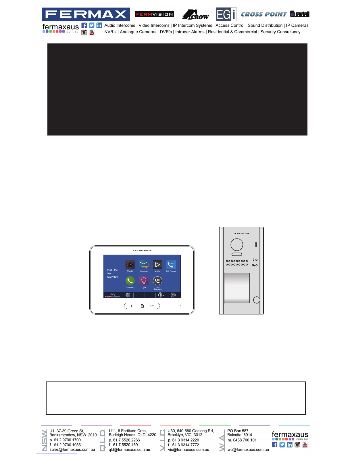
USER MANUAL
FVI-6013MEM FVI-6022C
FVI-6040-V2
2 WIRE SYSTEM
VIDEO DOOR PHONE SYSTEM
• Please read this manual carefully before using the product you purchase,and keep it well for future
use.
• Please note that images and sketch maps in this manual may be different from the actual product.
Page 2

-2-
CONTENTS
Front panel ............................................................................................................................ 4
Terminal Description ............................................................................................................ 5
Mounting ............................................................................................................................... 7
Quick Guide .......................................................................................................................... 8
Screen................................................................................................................................... 11
Answering a call .................................................................................................................. 12
Pan-tilt & Zoom .................................................................................................................... 14
Adjusting screen&volume .................................................................................................. 15
Door release ......................................................................................................................... 16
Calling other monitors ........................................................................................................ 16
Monitoring ............................................................................................................................ 17
Recording ............................................................................................................................. 18
Viewing images/videos ....................................................................................................... 19
Formating an SD card ......................................................................................................... 20
Copying recordings to SD card .......................................................................................... 20
Leaving messages............................................................................................................... 21
Viewing visitor messages ................................................................................................... 21
Mute function ....................................................................................................................... 22
Viewing calling records ...................................................................................................... 23
Message function ................................................................................................................ 24
Openning staircase light..................................................................................................... 25
Motion detect function ....................................................................................................... 26
Setting date and time .......................................................................................................... 27
Setting ring tone .................................................................................................................. 28
Setting ring volume ............................................................................................................. 28
Enabling/Disabling the operation sound ........................................................................... 29
Naming door station & camera .......................................................................................... 29
Setting monitor time ............................................................................................................ 30
Enabling/Disabling motion detect function ..................................................................... 30
Enabling/Disabling intercom function .............................................................................. 31
Changing the display language ......................................................................................... 31
Restoring to default setting ................................................................................................ 32
Entering installer setup....................................................................................................... 32
Connecting Basic One-to-one ............................................................................................ 36
Connecting Multi Door Stations ......................................................................................... 36
Connecting Multi Monitors ................................................................................................. 37
Page 3

-3-
Functions Setting Up .......................................................................................................... 39
Setting Door Station Address ............................................................................................ 40
Setting Unlock Mode ........................................................................................................... 41
Setting Unlock Time ............................................................................................................ 41
Setting Nameplate Illumination Mode ................................................................................ 42
Setting Night View LED Illumination Mode ....................................................................... 42
Setting Ring-back Tone ....................................................................................................... 43
Connecting Electric Lock ................................................................................................... 43
Specication ........................................................................................................................ 44
Cables and Requirments .................................................................................................... 45
Page 4
-4-
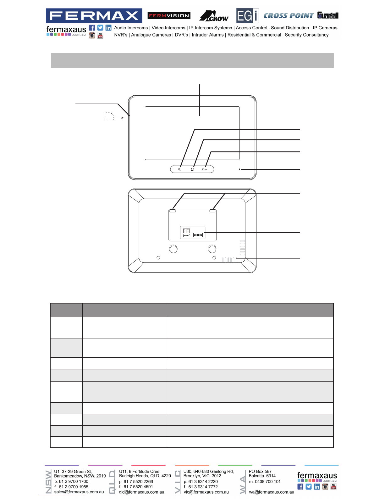
Front panel
Key functions
[1]
[6]
[2]
[3]
[4]
[5]
[7]
[8]
[9]
NO. Item Description
[1] Digital LCD touch screen
•See the next page for details
•Display the visitors' image
[2] Talk/Mon button
•Press to communicate hands free with visitor
•Press to view the outdoor condition in standby mode
[3] Menu button Press to open main menu in shortcut
[4] Unlock button Press to release the door
[5] Microphone Transmit audio from one station to other stations
[6] SD card slot Use to insert micro-SD card
[7] Mounting hook Use to hang up the monitor
[8] Connection port Bus terminal
[9] Speaker Send out sounds of ring tones,audios and alarms
L1
L2
SD card
1 2 3
ON DIP
4 5 6
Page 5
-5-
[11]
[10]
[12]
[13]
[9]
[1]
[3]
[4]
[8]
[7]
[6]
[5]
[2]
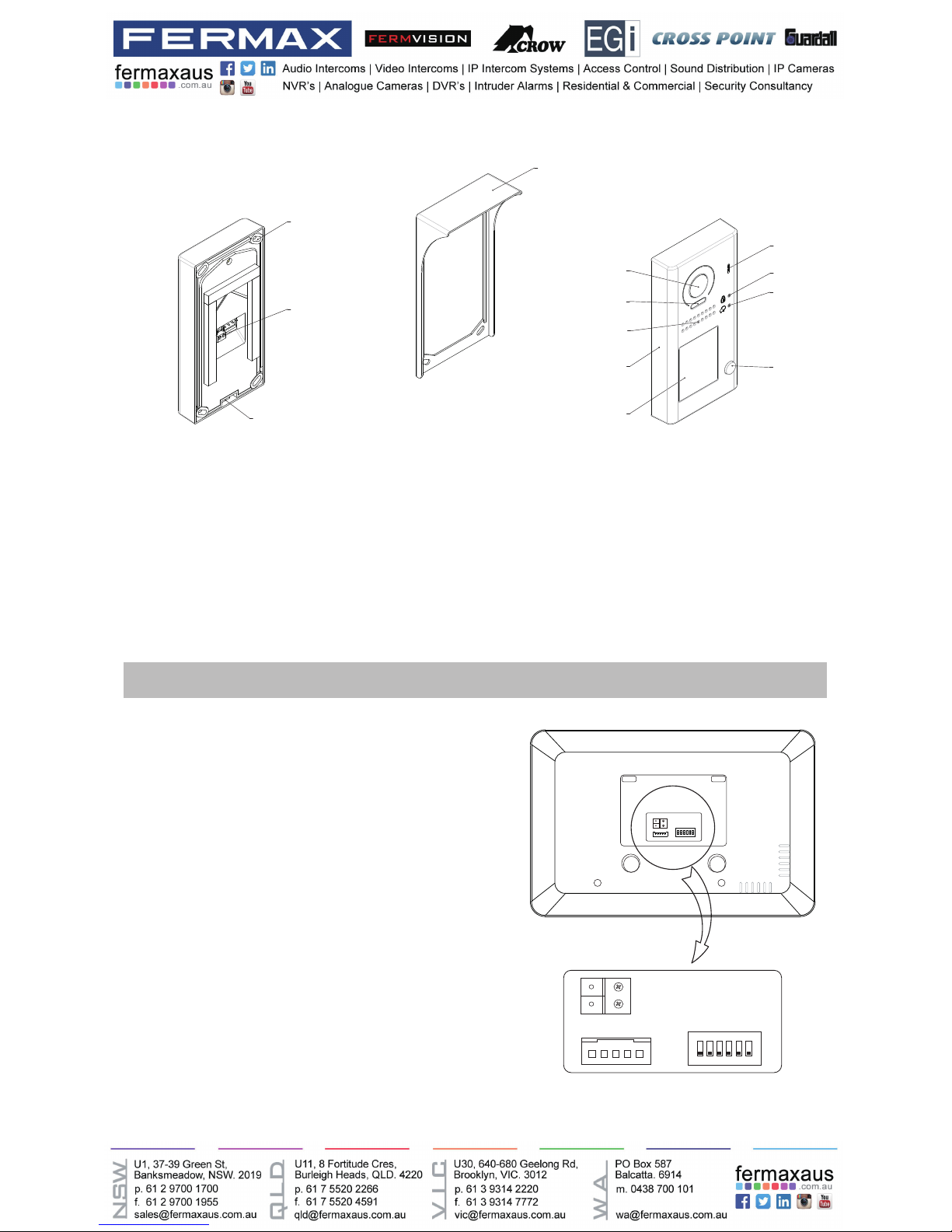
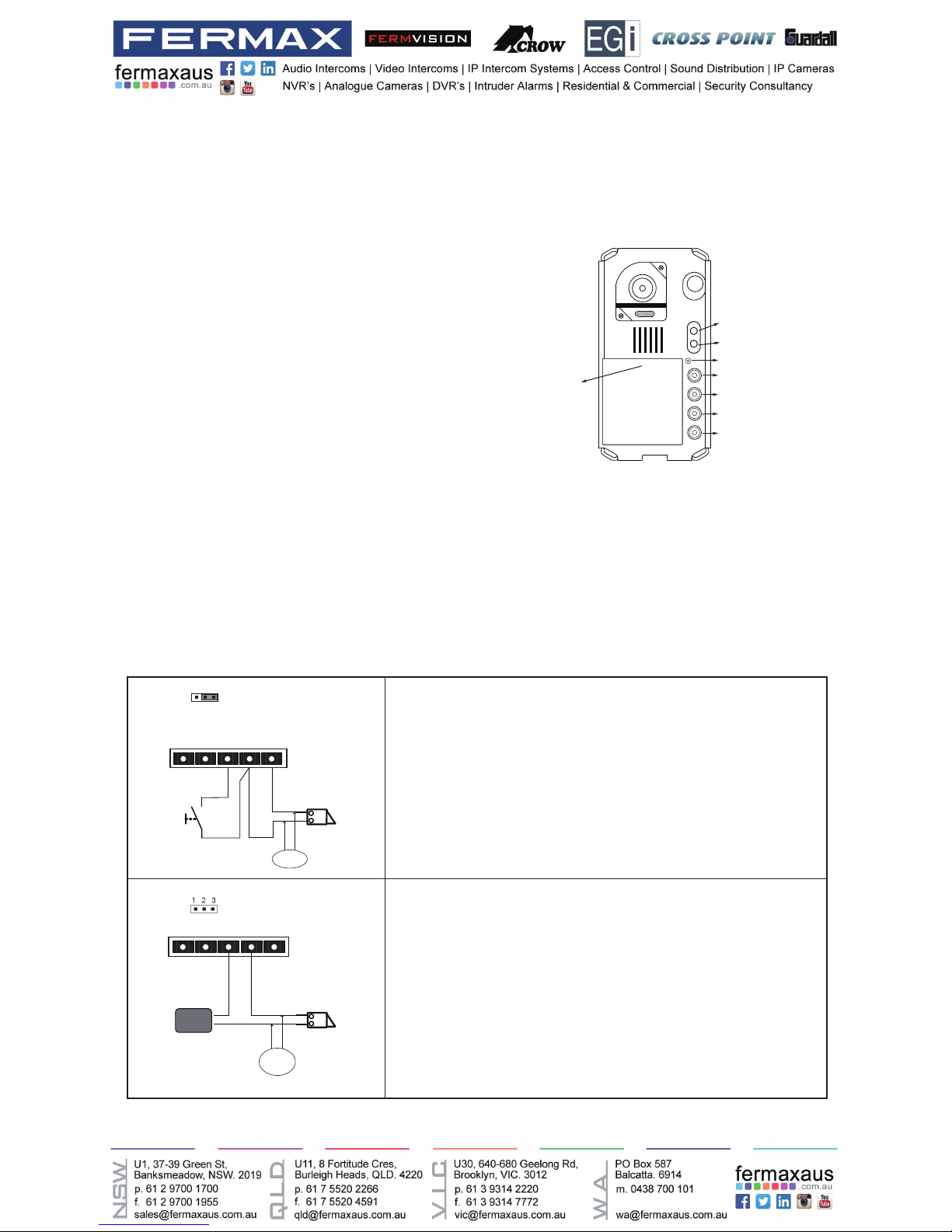
[1] Microphone
[2] UNLOCK indicator
[3] CALL indicator
[4] Call button
[5] Nameplate
[6] Front panel
[7] Speaker
[8] Night view LED
[9] Camera lens
[10] Rainy cover
[11] Mounting hook
[12] Connection port
[13] Screw hole
Terminal Description
1 2 3 4 5 6
ON DIP
L2
L1
DIP Switches
SW+
SW-
RING
GND
NC
L1
L2
1 2 3
ON DIP
4 5 6
L1,L2: Bus line terminal.
SW+,SW-: Extra door bell call but-
ton connection port.
Ring,GND: Extra buzzer connection
port.
NC: Undened.
DIP switches: Total 6 bits can be
congured.
• Bit1~Bit5: User Code setting.
• Bit6: Set to ON if the monitor is at
the end of the line or works with
DBC4A. Otherwise, set to OFF.
Page 6
-6-
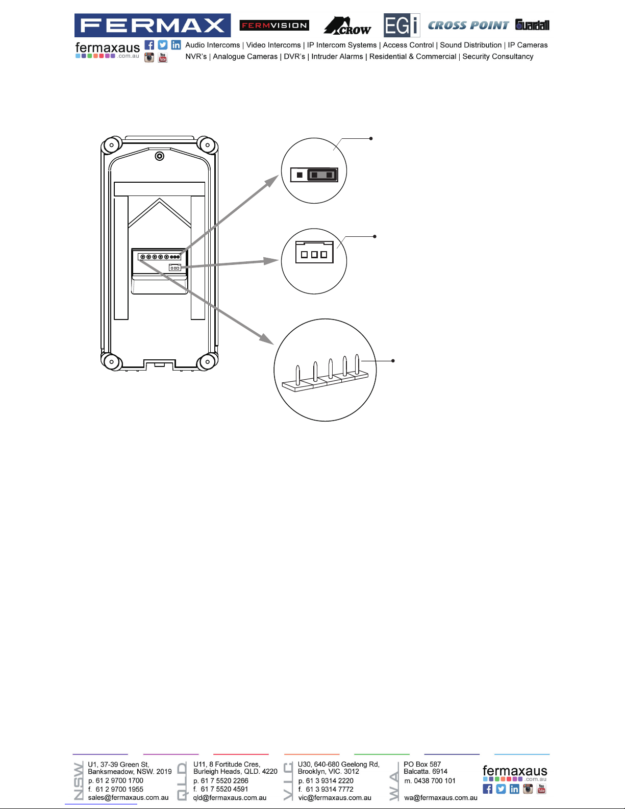
Lock Control Jumper:
To select the lock type.
Motion Detector Connect Port:
To connect external PIR motion detector.
Main Connect Port:
To connect the bus line and the electronic locks.
• L1,L2: Connect to the bus line, no polarity.
• PL: External lock power input, connect to the power positive(power +).
• S+: Lock power(+) output.
• S-: Lock power(-) output, connect to the power(-) input of locks(only when using the door
station to power the locks, if using the external power supply for the locks, the S- will not be
connected).
1 2 3
Lock Control Jumper
PIR Motion Detector
Connect Port
+12V
GND
PIR
L1
L2
PL
S+
S-
Main Connect Port
Page 7
-7-
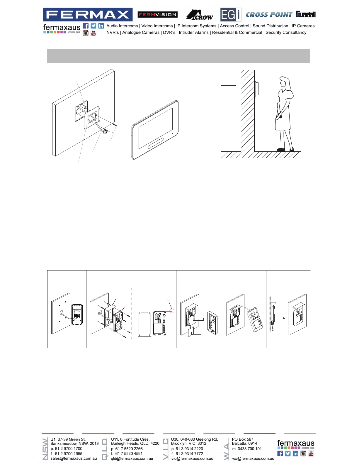
The installation height is suggested to 145~160cm.
1. Use screws to fasten the mounting bracket to the wall with mounting box.
2. Connect the 2 wire cables to the unit.
3. Mount the unit to the mounting bracket, make sure the unit is absolutely attached to the
mounting bracket.
Mounting
Mounting screw
x 2(included)
The unit
Mounting box
(size:86x86mm)
Mounting bracket
2 wire cable
145~160 cm
1 2 3 4 5
AcDbMLeader (ACDB_MLEADER_CLASS)
AcDbMLeader (ACDB_MLEADER_CLASS)
Rainy cover
Rainy cover
The distance between
the top of main unit
and rain cover should
be not less than 3mm.
Main unit
Main unit
≥3mm
1. Connect the cable correctly.
2. Drill holes in the wall to match the size of screw stoppers,then attach the rainy cover and
main unit to the wall, and the distance between the top of main unit and rain cover should be not
less than 3mm..
3. Install the name plate.
4. Attach the front panel to the main unit.
5.Usethespecialscrewdriverandthescrewstoxthepanel.
Page 8
-8-
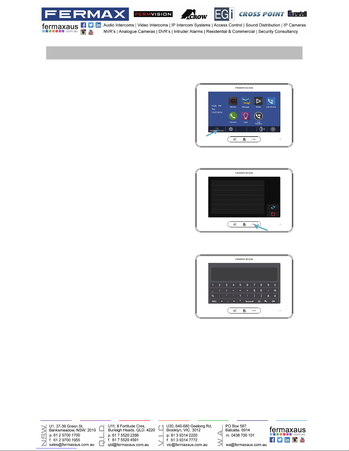
Quick Guide
Turn on monitor, press the Fermvision logo
located at the bottom left of the screen (Figure
1), and then hold down the key button (right
hand side of the main button) (Figure 2) until
a new menu comes up, which is shown on
Figure 3.
Use Table below for Dip switch Addressing.
Master – Addressed as 0
For slave monitor 1 Addressed as 1.
For slave monitor 2 Addressed as 2.
1. Accessing to programming menu – Monitors
2. Programming Monitor address (When using more than one monitor):
Figure 1
Figure 2
Figure 3
About
Local Address 00.00
Video Standard
AUTO
System Verson 00.01.00
Display Driver 1.0
Font 1.0
UI 1.0
INSTALLER SETUP
123
_
? + OK: Help Menu
@ + OK: Address Setting Menu
Page 9

-9-
Access to programming menu (see above) and then input code 84XX (where XX goes from 01 to
99 seconds),
nallypressOKtoconrm.
E.G:
For a door opening time of 8 seconds: input code 8408 and press the button OK
Access to programming menu (Figure 3) and input one of the following codes followed by OK
button.
Turn the Green Light off - 8057
Turn the Green Light on - 8052
3. Unlock Time
4. Monitor button light:
ON(1)
=
OFF(0)
=
ON
ON
ON DIP
1 2 3 4 5 6
Bit state Setting Bit state Setting
1 2 3 4 5
6
ON DIP
1 2 3 4 5
6
ON DIP
When monitor is not
at the end of bus line.
When monitor is at
the end of bus line.
Bit-6 switch setting
Page 10
-10-
Door lock controlled with internal power
Power on to unlock. (12V output, up to 250mA).
EB: Exit button (Door lock control is not timed by the exit
button)
Door lock controlled with dry contact
The inside relay contact is restricted to AC or DC 24V/3A.
The jumper must be taken off before connecting
Note: It is advisable to always use a separate power supply
for the electric latch, as well as placing a varistor at both
terminals of the electric latch.
EB: Exit button (Door lock control is not timed by
the exit button)
See Figure 1, press KEY_SET button, then
press KEY_ X once (where X goes from 1-4),
wait 10 seconds or press KEY_SET button
four times to save the settings.
E.G.:
For door station 1: KEY-SET, KEY_1, press
KEY_SET four times.
For door station 2: KEY-SET, KEY_2, press
KEY_SET four times.
Figure 1
6. Electric Lock Connection
5. Programming Door Station address (When using more than one door
station)
KEY_1
KEY_2
KEY_3
KEY_4
KEY_SET
LED_UNLOCK
LED_TALK
LED_NAME
LOCK
Take off the Jumper
POWER
SUPPLY
BUS PL S+S-
VARISTOR
EB
*
LOCK
BUS PL S+S-
Jumper position in 2- 3
1 2 3
VARISTOR
Page 11
-11-
Screen
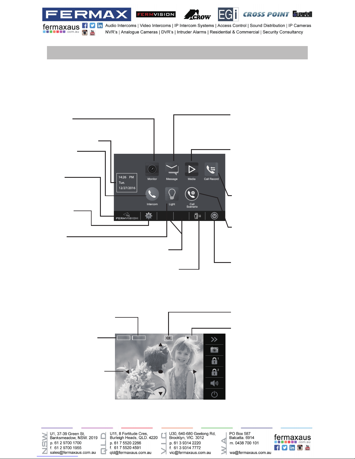
The Main menu is your starting point for using all the applications on your monitor. You can cus-
tomize your Main menu to display your logo.
Touch anywhere of the screen on monitor in standby mode, the Main menu will appear as follow:
CLOSE
Touch it to turn off the screen
and make the monitor in standby
mode.
SETTINGS
Touch it to enter
setup page.
Displays which door station
is calling.
Shows status of talking,unlocking
ect.
Displays talking time.
5 direction pad button,
zoom&pantilt the picture.
LIGHT
Touch it to light up the
staircase light via RLC.
MOTION DETECT
Touch it to enter motion
detect options.
MONITOR
Touch it to view outdoor condition.
MESSAGE
Touch it to write messages or
review the received/sent out
messages.
MEDIA
Touch it to play recorded images
or videos from door stations.
Review messages left by visitor.
See infos of memory/SD.
CALL RECORD
Touch it to see calling in/calling
out records or missed calls .
CALL SCENARIO
Touch it to activate the functions
of Mute,Left message and Divert
call.
INTERCOM
Touch it to enter
intercom selections.
Current date and time
Status bar
LOGO
Touch it to view Device
infos.The logo can be
customized.
Main Menu
While talking with a door station
00:10 DS-1
REC
Note: The 5 direction pad operation should make effective with sh-eye door station.
Blinks while recording.
Page 12
-12-
Answering a call
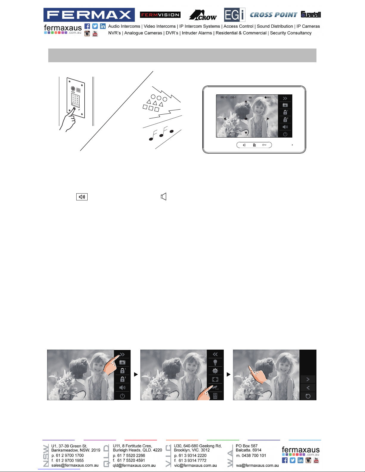
• When there is a call from a video door station.The call tone sounds, an image will be dis-
played on the screen.
• Touch
icon on screen or press
TALK/MON button on the panel, begin communicat-
ing hands free with the visitor for 90 seconds.
• While communicating with the visitor, unlock the door, capture images/videos and adjust
screen&volume are available. More details,please refer to the following descriptions.
Note: 1.If nobody answers the phone, the screen will be turned off automatically after 40 seconds.
2.The 5 direction pad operation should make effective with sh-eye door station.
It’s available to select cameras to monitor while being called.
Max.16 cameras can be selected to monitor, 4 cameras is default.
Follow the steps:
Monitoring cameras while being called/talking
00:10 DS-1 00:10 DS-1
Normal
Monitor Select
CM-1
CM-2
CM-3
CM-4
Page 13
-13-
• Touch icon on screen or
TALK/MON button on the panel to complete the communi-
cation.
To complete communication
Note: Communication also ends automatically after 90 seconds.
1.Receiving a call while talking with a door station
2.Receiving a call while talking with other monitors
• Other door stations calling is forbidden
• Conclude current talking to answer the new call-in
• The talking will stop immediately, call tone sounds in normal.
• The video image from the door station is displayed on the screen, talking,unlock,capture
images/videos, adjust screen&volume are available.
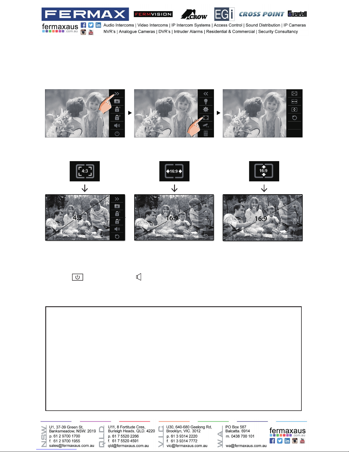
It’s available to adjust image scale while being called. Total 3 image modes can be selected.
Follow the steps:
Compare the difference of these 3 image modes:
Adjusting image scale while being called/talking
00:10 DS-1 00:10 DS-1
Normal
00:10 DS-1
Page 14
-14-
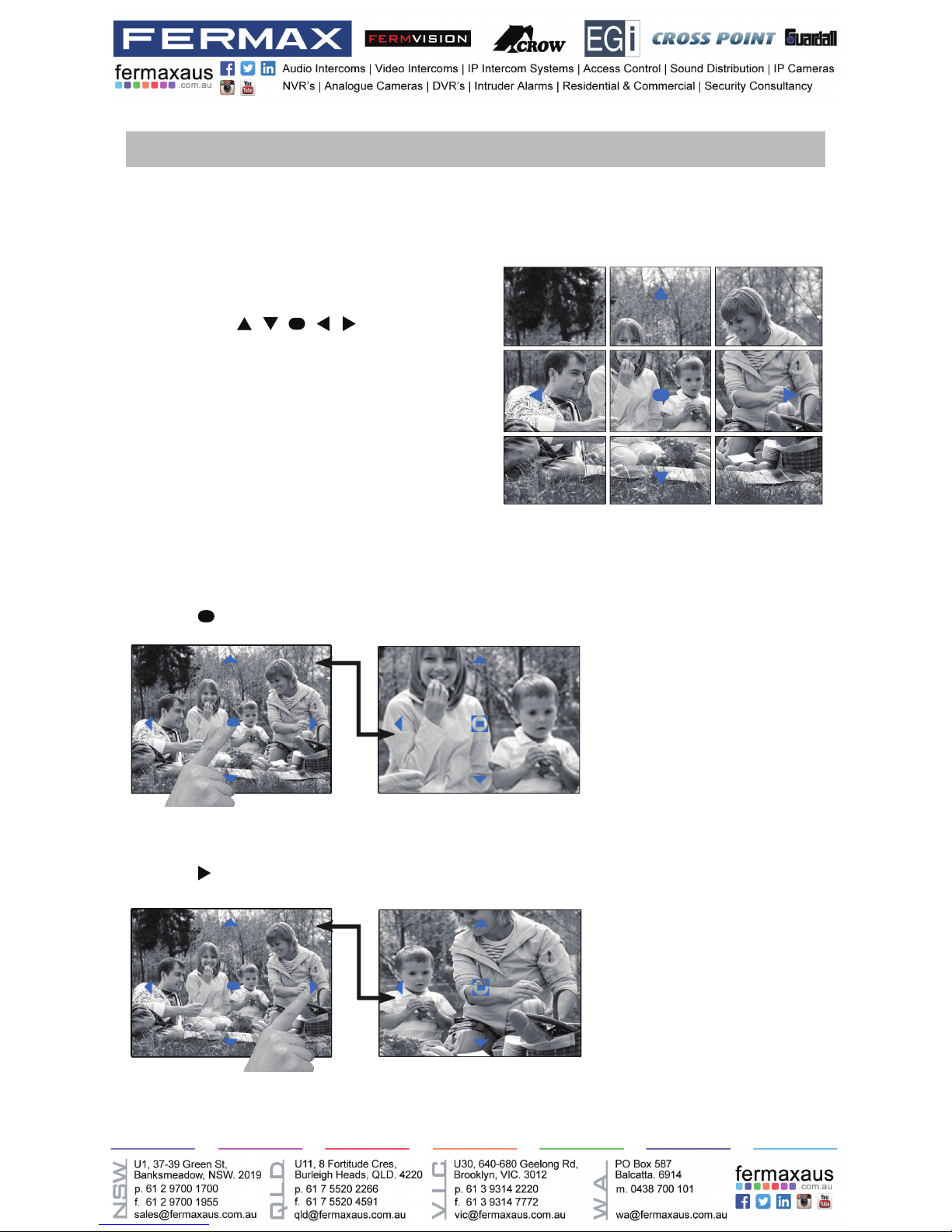
Pan-tilt & Zoom
It is available to adjust the display mode for viewing images at a sh-eye door station by using
the 5 direction pad button.
Here are some examples:
• Touch
icon to zoom the center position.
Note:
1.The zoom&pantilt function should make effective
withsheyedoorstation.
2.The edge of pantilt image will not be displayed.
When an image at a door station is
displayed,move to the desired position
by touching on the
screen to view the image in zoom mode.
• Touch
icon to zoom the right position.
Page 15
-15-
Adjusting the speaker volume
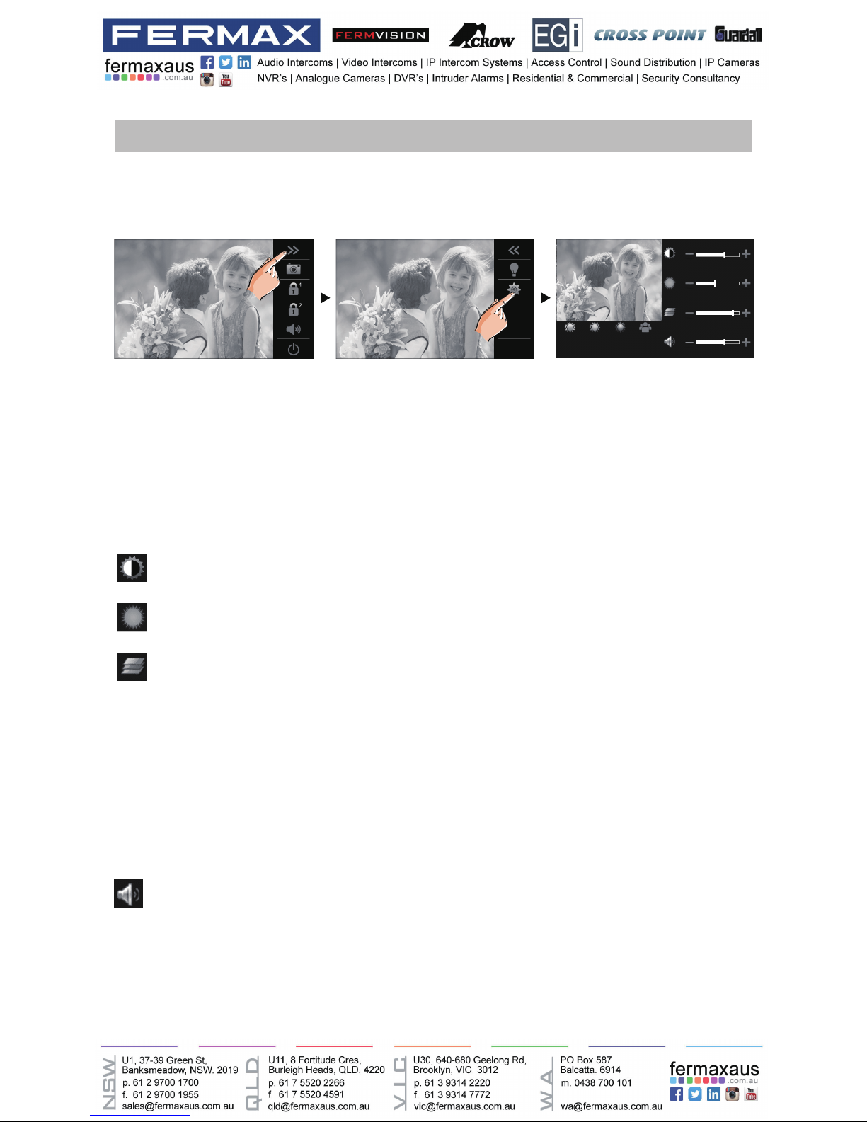
Adjusting images
Adjusting screen&volume
While receiving a call from door station, or monitoring /communicating with the visitor,you can
adjust the screen and speaker volume. Follow the steps:
Total 4 scene modes can be selected in sequence:Normal, Brightly, Soft and User.Whichever
mode you choose, there will be a corresponding value for contrast,brightness and color.
You should knowthat the contrast,brightnessand colorcan bemodied freely,butthis action
should be at the User scene mode.
Volume can be adjusted at any time.
Adjusting range: 0 (mute), 1 - 9.
Adjust the contrast of the screen,the range is 0~9. Touch - or + to change the level.
Adjust the brightness of the screen ,the range is 0~9. Touch - or + to change the level.
Adjust the color of the screen,the range is 0~9. Touch - or + to change the level.
Touch - or + to reach desired level.
00:10 DS-1 00:10 DS-1
Normal Brightly Soft User
Note: The adjustments have no effect on the recorded images.
Page 16

-16-
Calling monitors in the same room
Door release
Calling other monitors
It is available to release the door during a call-in, communication,or while monitoring a door
station.
It is available to call between monitors in the same room or in the same system,or call the
Guard Monitor.Follow the steps to activate the functions:
1. Touch [Inner Broadcast] icon on one of monitor, all other monitors in the same room can
automatically receive messages without answering the call. Note that all other monitors will not
open the screens.
2.Touch [Inner Call] icon on one of monitor, all other monitors in the same room will ring at the
same time,whichever monitor answers the call, conversation is started, other monitors will stop
ringing at once.(Calling ends automatically after 30 seconds if nobody answers the call)
00:10 DS-1
1
Touch either or icon on the
screen or press
UNLOCK button on
the the panel to release door. The door lock
is released for the set door release time.
(if two locks are connected to door station,
touch
icon to release the second lock.)
00:10 DS-1
* Use " " or "
" to adjust the microphone volume.
* Touch
icon to end the calling.
Page 17

-17-
Calling other monitors in the same system
Calling the guard monitor
Touch [Name list Call] icon on monitor, the users in the same system will be displayed.
Just select one target, touch
icon to call the corresponding user. If the call is
answered,conversation is activated.
A Monitor can be assigned as Guard Unit Monitor; when the Guard Unit Monitor answers the
call, conversation with the guard person is started..
You can monitor the entrance at any time via the monitor.
1.Touch anywhere of the screen on monitor in standby mode.
2.Touch [MONITOR] icon on main menu page to enter Monitor select page.
*Note: Press
TALK/MON button on the panel in standby mode to monitor the master door station in shortcut.
Monitoring door stations/cameras:
• DS1~4 and CAM1~4 can be selected to monitor individually if the system install multi door
stations/cameras.See the following steps:
[ 01 ] Jim. Zhang
[ 02 ] Calo. Liu
[ 03 ] Jacko. Zhang
[ 04 ] Philips. Chen
[ 05 ] Hebe. Zhang
[ 06 ] Tony. Li
Name List
Note:
* Use " < " or " > " to scroll pages.
* Touch "
" to rename.
* Touch "
" to redial when the icon is on
the screen.
* Calling ends automatically after 30 seconds if
nobody answers the call.
Monitoring
00:10 DS-1
Monitor Select
DS-1
DS-2
DS-3
CAM-1
DS-4
CAM-2
00:10 DS-1
* During monitoring, images can be viewed, but audio cannot be heard.
* If there is a visitor at the entrance, touch
icon on screen to begin communication with
door station.
Page 18

-18-
Recording
3.To end monitoring
Touch
icon on the screen or press
TALK/MON button on the panel.
* Monitoring also ends automatically after 30 seconds.
Video Quad Monitoring:
If the system installs multi cameras via QSW. Video quad monitoring is available.
• On Monitor select page,
touch “ > “ icon to scroll next page.
• Select “QUAD-1” item to activate video quad monitoring, see the following steps:
Available functions during monitoring(not including video quad monitoring)
•Pantilt&zoom
•Adjustingimages(imagescale/bright/color/contrast)
•Doorrelease
•Volumecontrol
•Manualrecording
Videos and images are possible to be recorded, both automatic recording and manual record-
ing are available.
00:10 DS-1
REC
Blinks
Automatic recording
• Recording starts after 3 seconds while
receiving a call.
• While recording, “
REC” blinks on the
screen.
• Capture one picture automatically for
each calling.
00:10 DS-1
Monitor Select
CAM-3
CAM-3
CAM-4
CAM-4
CAM-1 CAM-2
QUAD-1
Monitor Select
DS-1
DS-2
DS-3
CAM-1
DS-4
CAM-2
* During monitoring, manual recording is available.
* Touch each one of video to switch to monitor the corresponding camera Independently.
Page 19

-19-
Video:008/020 2015/06/23 14:36:55
00:03 00:09
Therecordedimagesarestoredinthebuilt-inmemoryrst.
* Max.118 pictures can be stored in inner memory
* If a micro-SD card is installed, images can be copied to SD card.
* Max. 32G Micro SD card is supported.
Note:
* Automatic recording function cannot be cancelled.
* Automatic recording is not available while monitoring a door station. To save images while monitoring, see manual
recording below.
Manual recording
While being called,Touch
icon when an image is displayed.
Note:
* Manual recording is available at any time when
icon is on the screen.
* Manual recording is allowed in pantilt & zoom mode.
* Manual recording cannot be performed during automatic recording.
Viewing images/videos
The recorded images/videos can be playback on monitor. Follow the steps:
• On main menu page, touch [Media]->[Graphics Playback] icon, most recent recordings are
displayed (If insert a micro SD card,playback videos.Otherwise,playback images).
• Touch " < " or " > " to scroll through recordings, touch “
” to delete current image/
video(Please note that if the recordings are videos, touch "
" icon to start/pause the videos).
* If the monitor installed a micro SD card, the recording format is video, and recording time limited is 10s. The
videos will be saved on micro SD card directly. Otherwise,the recording format is image.
* A brand new SD card needs to be formatted by the monitor, then it can be used for video & audio recording.
To stop
Touch
icon on the screen during play.
Page 20

-20-
When copying is completed, "BKUP_PIC" folder is created on the Micro SD card. Copied im-
agesarestoredwiththefollowinglenames:
Recording Date
Recording Time
Micro-SDcardsneedtobeformattedwhenusingtheminthismonitorforthersttime.
* When formatting an micro-SD card, all existing data on card is erased.
* To EXPORT RECORDED IMAGES, refer to following item on this page.
* To VIEW SD CARD INFO, on main menu page, touch Multimedia->Memo information.
Note:
* This action will overwrite all existing images in the "BKUP_PIC" folder on the micro SD card.
* If the number of images or folders exceed the limit of micro SD card, they cannot be copied.
* The images on the micro SD card cannot be copied into the built-in memory.
* If copied is fail, try to format the SD card on the monitor.
20151119_115125.jpg
Copying recordings to SD card
Formating an SD card
You can copy recordings(videos/images) stored in the built-in memory to a SD card.
• On main menu page, touch [Media]->[Copy to SD], the information of "Copy Pictures To
SD?" will be asked.
• Touch
icon to copy. Touch icon to cancel.
* When a sound beep beep is sent out and a blue screen is displayed, formatting is complete.
* It may take some time until formatting has been complete.
1.On main menu page,touch Multimedia->Format SD Card. A notice message is displayed.
2. Touch
icon to continue with formatting. Touch icon to cancel formatting.
Page 21

-21-
Leaving messages
00:10 DS-1
Call Scenario
Normal
Do Not Disturb
Leave a Message,Immediately
Leave a Message,If No Answer
Divert, Simultaneously
Divert, If No Answer
Note:
* The time limited for leaving message is 10s.
* The status bar on main menu page will show "
" icon.
* Touch
icon on the screen to exit.
Viewing visitor messages
Visitor Message
01/N
06-23 15:22 DS-1
06-18 20:54 DS-1
06-12 11:06 DS-2
05-29 08:39 DS-3
05-27 21:43 DS-1
04-20 13:16 DS-4
This function is very useful when you are away home. Must insert a micro SD card to support
this function.
To activate the function, please follow the steps:
Two modes can be selected.
Leave a Message, Immediately: If you select this mode, when receiving calls from door sta-
tion, The system will prompt visitor to leave a voice message immediately.
Leave a Message, If No Answer: If you select this mode, door station calls indoor monitor
rst,ifnobodyanswers the call within 30seconds, thesystem will promptvisitor to leavea
voice message.
All visitor messages from door stations will be recorded and can be reviewed afterwards. To
support this function, the Call Scenario mode should be set to “Leave a Message,Immediately”
or “Leave a Message,If No Answer”. Please refer to the above in detail.
On main menu page, touch [Multimedia]->[Visitor Message] icon, the most recent visitor’s
messages are displayed.
Page 22

-22-
Mute function
If you don't want to be disturbed,for example,at night. Activating the mute function is necessary
for you.Follow the steps:
00:10 DS-1
Call Scenario
Normal
Do Not Disturb
Leave a Message,Immediately
Leave a Message,If No Answer
Divert, Simultaneously
Divert, If No Answer
Do Not Disturb: If you select this mode, calling from door station or other monitors can not be
made effect.
Note:
* This function will perform immediately if selected,and the status bar on main menu page will show "
" icon.
* Touch
icon on the screen to exit.
You can review who is visiting at some time.
1. Touch one of the visiting list.
2. Touch
icon to show the caller's image.
Visitor Message
01/N
06-23 15:22 DS-1
06-18 20:54 DS-1
06-12 11:06 DS-2
05-29 08:39 DS-3
05-27 21:43 DS-1
04-20 13:16 DS-4
Note:
* Max. 100 messages can be displayed.
* Must insert a SD card to support this function.
Scroll to next page
Delete the selected recording
Playback visitor's video&audio
Scroll to last page
Exit
When touch the
item," >> " icon
will be displayed.
Current page
Total page
Page 23

-23-
Viewing calling records
All calls from door station or other monitors will be recorded and can be reviewed afterwards.
On main menu page, touch[Call Record] icon, the most recent call records are displayed.
Call Record
01/05
06-23 15:22 Calo.Liu
06-18 20:54 Smith
06-12 11:06 Vincent.Yang
05-29 08:39 Allen.Chen
05-27 21:43 Hebe.Zhang
04-20 13:16 Ben.Wu
Current page
Total page
Calling date&time
Calling source
Scroll to next page
Scroll to last page
Exit
Be called in
Call out
You can review who is calling at some time.
1. Touch one of the calling list.
2. Touch
icon to show the caller's image.
Call Record
01/05
06-23 15:22 Calo.Liu
06-18 20:54 Smith
06-12 11:06 Vincent.Yang
05-29 08:39 Allen.Chen
05-27 21:43 Hebe.Zhang
04-20 13:16 Ben.Wu
Call Record
01/05
06-23 15:22 Calo.Liu
06-18 20:54 Smith
06-12 11:06 Vincent.Yang
05-29 08:39 Allen.Chen
05-27 21:43 Hebe.Zhang
04-20 13:16 Ben.Wu
Note:
* If the arrow display in red, that means the call is missed.
* If the missed calls have been reviewed,the arrow will change to blue.
* If it's blue,that means the call is answered.
* Max. 100 calling records can be displayed
* When the capacity is full,the oldest calling records will be deleted automatically to make room for new records.
Scroll to next page
Delete the selected recording
Playback caller's image
Scroll to last page
Exit
When touch the
item," >> " icon
will be displayed.
Page 24
-24-
Message function
The messages received or sent out can be reviewed on monitor, and you can write messages
between monitors.
1.Reviewing received messages:
• On main menu page,touch [Message]->[Inbox] icon,the most recent received messages will
be displayed.
• Select one of the messages to view the contents.
2.Reviewing sent out messages:
• On main menu page,touch [Message]->[Outbox] icon,the most recent sent out messages
will be displayed.
• Select one of the messages to view the contents.
Note:
It's available to reply messages or delete messages on Inbox/Outbox page.
Use " < " or " > " to scroll pages.
Touch
icon on the screen to exit.
3.Writing a message:
• On main menu page,touch [Message]->[Write a Message] icon, and then select the sending
address.
• Write a message by touching the on-screen keypad.Up to 78 characters can be entered for a
message.
• Touch the key " OK " to send the message.
Page 25

-25-
Sending address
Cursor
Switch the keypad
between alphabet
and numbers
Keypad type
abc- Alphabet keypad
123-Number keypad
Edit box
Delete the last character
Press to send the SMS
Exit current page
[02]
abc
-
Enter key
Space key
Insert a space.
Move the cursor.
Opening staircase light
Note: The staircase light should be connected on the system, and this function should be sup-
ported by RLC. Please refer to RLC user instruction in detail.
Touch [Light] icon on main menu page or touch
icon during monitoring or talking to open
the staircase light, the staircase light will be turned off automatically after 60 seconds.
*Touch [Light] icon again to turn off the light.
or
*Touch icon again to turn off the light.
00:10 DS-1
Page 26

-26-
Motion detect function
This function is available only if the setting of Motion Detect Enable is selected.
This function should make effective by door station with motion detection.
Follow the steps:
00:10 DS-1
• Detection off: close all motion detections of door station.
• Detection on: activate the motion detect function,the door station motion detection should be
activated individually.
• Detection once: respond motion detect function immediately,the door station motion detec-
tion should be activated individually.
The door station is equipped with a terminal to
connect external motion detector.
If the external motion detector is connected to
the system,following functions will be effective:
If detect someone passing by, the door station
can be activated operation to unlock or turn on
light.
12V
Motion
detector
GND
PIR
* Please contact with supplier for more details about detector connection.
Page 27

-27-
Setting date and time
Note: 1.You can also synchronize the system time.
2.Touch
icon to exit and return to main menu page.
Date&Time
Sync From System Clock
RTC Server Enable
2016 03 08 14 26 30
You can correct the current date and time at any time by following the procedure below.
1.On main menu page, touch
settings icon ->[Date&Time]. Or directly touch current date
and time area in shortcut to enter Date&Time setting page.
2.Touch the setting target of month, date, year, hour,minute and second individually, then touch
/ icon to change the value.
3.Whenthesettinghasnished,touch
to save the settings.
The following is taken door station1 for example.
1.On main menu page,touch
icon.
2. Touch DS1 Detection item.(the door station with motion detector should be online)
* The detection settings for other door staions are the same as door station1.
Should be selected to
activate door station1
motion detection
The reaction for door
station
(Multiple Choice)
Duration time for motion detection
06 2200 00
Save settings and exit
Unsave and exit
The reaction for monitor
(Single Choice)
Increase timing
decrease timing
Setting door station detection:
*On main menu page, touch [Multimedia]->[Motion Detection] icon, the most recent motion
detect records are displayed.
Page 28

-28-
Setting ring tone
Note: 1.If the door ring mode is selected to United, the ring tone of Door1/2/3/4 must be the same.
2.Touch
icon to exit and return to main menu page.
The ring call tone can be set individually to distinguish different calling sources. Total 20 tones
can be selected.
1.On main menu page, touch
settings icon ->[Sounds].
2.Touch the setting target of door tone,intercom tone,door bell tone and alert tone individually,
then touch
/ icon to change the tone. Settings will perform immediately.
The day/night ring volume can be set individually.The setting range is 0~9.
• On main menu page, touch
settings icon ->[Sounds].
• Select the Volume setting item,touch
/ icon to adjust the levels. Settings will perform
immediately.
Note: 1.The day time is from 06:00am to 18:00pm. the night time is from 18:00pm~06:00am.
2.Touch
icon to exit and return to main menu page.
Setting ring volume
Page 29

-29-
Current renamed door stationCurrent name is displayed here.
Switch the keypad
between alphabet
and numbers
Keypad type
abc- Alphabet keypad
123-Number keypad
Edit box
Delete the last character
Save the setting
Exit current page
DOOR1 RENAME
abc
DS1_
Enter key
Space key
Insert a space.
Move the cursor.
3.Rename the door station by touching the on-screen keypad.
* Up to 12 characters can be entered for a name.
Enabling/Disabling the operation sound
You can make a beep sound for the monitor when touching the screen.
1.On main menu page, touch
settings icon ->[Sounds].
2.Click Touch Key Sound On setting item, when “
“ symbol is displayed in the frame ,
the setting is activated.Click the item again to cancel.
Naming door station & camera
You can name the door stations & cameras by entering characters.
1.On main menu page, touch
settings icon ->[More...].
2.Select door station to rename.A keypad is shown.
Page 30

-30-
Setting monitor time
The monitor time can be changed at any time. It's available to set 30s,40s,50s,1min,2min,3min,
4min,5min,6min,7min,8min,9min,10min.
* 30s is the default monitor time.
1.On main menu page, touch settings icon ->[More...].
2.Select Monitor Time Set item.
3.Touch
/ icon to adjust the levels. Settings will perform immediately.
Enabling/Disabling motion detect function
You can make it possible (ENABLE) or not (DISABLE) to activate motion detect function from
this monitor.
1.On main menu page, touch
settings icon ->[More...].
2.Click Motion Detect Enable setting item,when “
“ symbol is displayed in the frame , the
setting is activated.Click the item again to cancel.
*If this setting item has not been selected, the motion detect function is forbidden, and the Montion detect icon
will not display on main menu page.
Page 31

-31-
The default language can be customized.But you can change it to the language you need at
any time. Follow the steps:
•On main menu page, touch
settings icon ->[Language].
•Touch desired language and select
to save the setting.
*If the target language is not found in the window, touch / icon to scroll next page.
Changing the display language
Language
English
Turkish
Greek
Hebrew
Spanish
French
Enabling/Disabling intercom function
You can enable or disable intercom function from this monitor.
1.On main menu page, touch
settings icon ->[More...].
2.If select Intercom Disable item,the intercom function is forbidden.
*In default setting, intercom function is enable for the monitor.
Page 32

-32-
The restore to default function allows the user to recover the settings to factory setting.
• On main menu page, touch
settings icon ->[About].
• Touch icon, a message of "Restore To Default?" will be asked.
• Touch
icon to start the restore. T
ouch icon to cancel.
* Touch [Logo] icon to enter About page in shortcut.
* If restoring to default is completed,a sound beep will be sent out.
Restoring to default setting
About
Local Address 00.00
Video Standard
AUTO
System Verson 00.01.00
Display Driver 1.0
Font 1.0
UI 1.0
Logo icon
•On main menu page, touch [Logo] icon to enter About page.
•When the screen stay in About page,press UNLOCK button on front panel and hold for
2 seconds.
• A keypad is shown.
Refer to the followings:
Entering installer setup
00:10 DS-1
About
Local Address 00.00
Video Standard
AUTO
System Verson 00.01.00
Display Driver 1.0
Font 1.0
UI 1.0
INSTALLER SETUP
123
_
? + OK: Help Menu
@ + OK: Address Setting Menu
Page 33

-33-
Maximum 4 monitors can be connected in one apartment, one master monitor together with 3
slave monitors, so you should set the address correctly.(Note:must have one monitor to be set
as a master monitor)
• Select Master/Slave Setting item,touch
/ icon to scroll to next item,settings will perform
immediately.
Setting master/slave monitor
Input the key “@ and ok” to open Address Setting menu.
Refer to the followings:
Entering Address setting page
INSTALLER SETUP
123
_
? + OK: Help Menu
@ + OK: Address Setting Menu
Input the key “? and ok” to open Help instructions menu.
Refer to the followings:
Entering Help page
Help 01/04
2412:Reset to Default Setting
2499:Format Memory
2810:MCU Code Update
2811:TFT,UI Code Update
2812:Consumer Tune Update
2813:Format SD Card
INSTALLER SETUP
123
_
? + OK: Help Menu
@ + OK: Address Setting Menu
Code Setting Item Code Setting Item
2412 Reset to Default Setting 8018-8020 Video Display Standard
2499 Format Memory 8040-8050 LED Color Setting For Calling
2810 MCU Code Update 8051-8055 LED Color Setting For Standby
2811 TFT,UI Code Update 8300-8301 Auto Rec ON/OFF
2812 Consumer Tune Update 8302-8303 Manual Rec ON/OFF
2813 Format SD Card 8401-8499 Unlock Time
2910 Broadcast Namelist 9006-9007 Unlock Alert Disable/Enable
8004-8005 Guard Unit Enable 9008-9010 Tune Source For Default/Custom
8008-8009 Date Format 9011-9012 NameList First Name.”00/01”
8010-8011 Unlock Mode:Close/Open 9017-9019 Touch Key Sensitivity Adjust
8012-8013 Time Format:12 hour/24 hour 9020-9021 Hearing Aid Function On/Off
8016-8017 Bypass Enable/Disable 9030-9039 Fish Eye Control
Page 34

-34-
OnDTsystem,everyapartmentmustassignauniqueidenticationcalledUser Code.
There are two setting modes for address setting,DIP switcher and manual input .
Setting user code
In default mode,when receiving a call,the master and slave monitors will ring at the same
time,and just the master monitor can display the image while the slave monitors will not. But the
settings can be changed,you can set the master monitor and all the slave monitors to panel on
at the same time when being called.
• Click “ Slave Panel On When Being Called” item,when “ “ symbol is displayed in the
frame , the setting is activated.
• Click the item again to cancel.
Setting slave monitor panel on
This monitor is assigned with DIP setting instructions.
OnAddresssettingpage,selectDIPSwitcherSetAddresssettingmoderstly,thentouch
icon, total 32 DIP codes will be displayed.
DIP Switcher Set Address
TheDIPswitchesareusedtosettheusercodeforeachmonitor.Total6bitscanbecongured.
• Bit-1 to Bit-5 are used for user code setting. The value range is from 0 to 31, which have 32
different codes for 32 apartments.
• When multi monitors need to be installed in one apartment, these monitors should use the
same user code, and the master/slave mode should be set on the monitor. (Details refer to
the section of Setting Slave Monitor)
• Bit-6 is bus line terminal switch, which should be set to “ON” if the monitor is at the end of
bus line, otherwise be set to “OFF”.
ON(1)
=
OFF(0)
=
ON
ON
ON DIP
1 2 3 4 5 6
Bit state Setting Bit state Setting
1 2 3 4 5
6
ON DIP
1 2 3 4 5
6
ON DIP
When monitor is not
at the end of bus line.
When monitor is at
the end of bus line.
Bit-6 switch setting
Page 35

-35-
Manual Input Address
It’s available to input the address manually for this monitor.
• Total 32 numbers to be set, from 00~31.
• When multi monitors need to be installed in one apartment, these monitors should use the
same user code, and the master/slave mode should be set on the monitor. (Details refer to
the section of Setting Slave Monitor)
1.On Address setting page,select Manual Input Address setting mode, then touch
icon, a
keypad will be displayed.
2.Input the code by touching the digital number.
3.Touch “OK” key to save, code setting complete.
4. Touch “
“ key to exit.
Cursor
Switch the keypad
between alphabet
and numbers
Keypad type
abc- Alphabet keypad
123-Number keypad
Edit box
Delete the last character
Save setting
Exit current page
INSTALLER SETUP
123
_
00-31
Space key
Insert a space.
Move the cursor.
Page 36

-36-
•Max.4 door stations can be connected to the system.
•Ensure to set the correct address for each door station, Refer to Page 41 for more details
about the address setting of door stations.
Connecting Basic One-to-one
Connecting Multi Door Stations
BUS(IM) BUS(DS)
-
+
L1 L2 PL S+ S-
ID=0
Code=0, DIP6=on
1 2 3 4 5 6
ON DIP
L2
L1
DIP Switches
FVI-6017PC6
AC~
100~240VAC
100~240VAC
FVI-6011DBC4A
A B C D
OFF
ON
Impedance
switch
BUS(IM) BUS(DS)
FVI-6017PC6
AC~
ID=0
1
st
door station
ID=1
2nd door station
ID=2
3rd door station
ID=3
4th door station
L1 L2 PL S+ S- L1 L2 PL S+ S- L1 L2 PL S+ S- L1 L2 PL S+ S-
To monitors
•The door station is also compatible with other monitors which are provided by our company.
Page 37

-37-
Basic IN-OUT Wiring
Connecting Multi Monitors
• The door station is also compatible with
other monitors which are provided by our
company.
• Distributor is unnecessary in full audio
system, and IN-OUT mode is recommended.
• For the last monitor connected to the
system, DIP6 should set to ON.
ID=0
Code=0, DIP6=off
Code=14, DIP6=off
Code=15, DIP6=on
BUS(IM) BUS(DS)
FVI-6017PC6
AC~
100~240VAC
Optional functional module
QSW image quad splitter module
SCU camera module(max.4)
CCU camera converter
SCUQSW
DT-CCU
Camera
BUS
GNDVIDEO
BUS BUS
2-WIRE SYSTEM
GND
VEDIO
Page 38

-38-
• The door station is also compatible with other monitors which are provided by our company.
FVI-6011DBC4A
A B C D
RLC
FVI-6011DBC4A
OFF ON
Impedance
switch
BUS(IM) BUS(DS)
ID=0
FVI-6017PC6
AC~
100~240VAC
Optional functional module
BDU
BDU bus amplifier module
RLC staircase light controller module
FVI-6011DBC4A 2/4 inputs branch distributor
Code=0, DIP6=on
Code=2, DIP6=onCode=3, DIP6=on
Code=1, DIP6=on
FVI-6011DBC4A
A B C D
OFF ON
Impedance
switch
Code=12, DIP6=on
Code=14, DIP6=onCode=15, DIP6=on
Code=13, DIP6=on
Star Topology Wiring With FVI-6011DBC4A
Page 39

-39-
Functions Setting Up
This section explains the settings of each
function,please refer to the following table:
To perform the settings for the function
you want,you should move away the met-
al front panel. Please refer to the sketch
map.
Each operation is indicated by the lighting
up of the LED indicator on the unit, and by
the sounding of the buzzer.
Order Setting items Setting range Default value
1 Setting door station address 0~3 0
2 Setting the unlock mode 0:opened/1:closed 0:opened
3 Setting the unlock time 01 to 99 seconds 1 seconds
4
Setting the nameplate
illumination mode
On/Off/Auto On
5
Setting night view LED
illumination mode
On/Off/Auto Auto
6 Setting ring-back tone
Ringing one time
Ring continuously
No ring-back tone
Ringing one time
KEY_1
KEY_2
KEY_3
KEY_4
KEY_SET
LED_UNLOCK
LED_TALK
LED_NAME
Page 40

-40-
Setting Door Station Address
Total4addressescanbecongured.Itcanbemodiedeitherbeforeorafterinstallation.
0 is default, to change the setting, please follow the steps:
UNLOCK Indicator:OFF
TALK Indicator:OFF
Buzzer
Beep+, Beep
UNLOCK Indicator:OFF
TALK Indicator:OFF
Buzzer
Beep+
In standby mode, press
KEY_SET button once
Press KEY_1 button to set
the first door station.
Press KEY_2 button to set
the second door station.
Press KEY_3 button to set
the third door station.
Press KEY_4 button to set
the fourth door station.
UNLOCK Indicator:OFF
TALK Indicator:OFF
Buzzer
Beep,Beep
UNLOCK Indicator:OFF
TALK Indicator:OFF
Buzzer
Beep,Beep,Beep
UNLOCK Indicator:OFF
TALK Indicator:OFF
Buzzer
Beep,Beep,Beep,Beep
ID=0,1st door station ID=1,2nd door station ID=2,3rd door station ID=3,4th door station
• If setting mode has not been exited, you can change the address of door station by pressing KEY1~4
freely.
• The LED_NAME indicator will always blink until exit out the setting mode.
• If without any operation in 10 seconds, it will exit out setting mode automatically.
• In this step,press KEY_SET button four times to exit out the setting mode manually.
Page 41

-41-
Setting Unlock Time
By default, the unlock time is 1s, but it can be changed,the setting range is 1s~99s.
Follow the steps:
UNLOCK Indicator:ON
TALK Indicator:OFF
Buzzer
Beep+, Beep
In standby mode, press
KEY_SET button three
times.
UNLOCK Indicator:ON
TALK Indicator:OFF
Buzzer
Beep,Beep......
Press and hold on KEY_2
button. The time you holding
on is the new unlock time.
• When entering time delayed setting, the buzzer sound one time every second.
• The LED_NAME indicator will blink all the time until exit out the setting mode.
• If without any operation in 10 seconds, it will exit out setting mode automatically.
• In this step,press KEY_SET button twice to exit out the setting mode manually.
Setting Unlock Mode
There are 2 unlock modes, Normally opened and Normally closed.
Normally opened is default, to change the setting, please follow the steps:
UNLOCK Indicator:ON
TALK Indicator:OFF
Buzzer
Beep+, Beep
In standby mode, press
KEY_SET button three
times.
UNLOCK Indicator:ON
TALK Indicator:OFF
Buzzer
Beep+
Press KEY_1 button to set
the unlock mode to
Normally opened.
UNLOCK Indicator:ON
TALK Indicator:OFF
Buzzer
Beep, Beep
Press KEY_1 button again
to set the unlock mode to
Normally closed.
Press KEY_1
• If setting mode has not been exited, you can change the unlock mode by pressing KEY1 circularly.
• The LED_NAME indicator will blink all the time until exit out the setting mode.
• If without any operation in 10 seconds, it will exit out setting mode automatically.
• In this step,press KEY_SET button twice to exit out the setting mode manually.
Page 42

-42-
Setting Nameplate Illumination Mode
There are 3 illumination modes for nameplate indicator, Normally on,Normally off and Auto.
Normally on is default, to change the setting, please follow the steps:
UNLOCK Indicator:ON
TALK Indicator:OFF
Buzzer
Beep+, Beep
In standby mode, press
KEY_SET button three
times.
UNLOCK Indicator:ON
TALK Indicator:OFF
Buzzer
Beep+
Press KEY_3 button to set
the nameplate illumination
mode to Normally on.
UNLOCK Indicator:ON
TALK Indicator:OFF
Buzzer
Beep, Beep
Press KEY_3 button again
to set the nameplate illumination mode to Normally off.
UNLOCK Indicator:ON
TALK Indicator:OFF
Buzzer
Beep, Beep,Beep
Press KEY_3 button again
and again to set the nameplate
illumination mode to Auto.
Press KEY_3
• If setting mode has not been exited, you can change the nameplate illumination mode by pressing KEY3
circularly.
• The LED_NAME indicator will blink all the time until exit out the setting mode.
• If without any operation in 10 seconds, it will exit out setting mode automatically.
• In this step,press KEY_SET button twice to exit out the setting mode manually.
Setting Night View LED Illumination Mode
There are 3 working modes for night view LED indicator, Normally on,Normally off and Auto.
Auto is default, to change the setting, please follow the steps:
UNLOCK Indicator:ON
TALK Indicator:OFF
Buzzer
Beep+, Beep
In standby mode, press
KEY_SET button three
times.
UNLOCK Indicator:ON
TALK Indicator:OFF
Buzzer
Beep+
Press KEY_4 button to set
the night view LED mode
to Normally on.
UNLOCK Indicator:ON
TALK Indicator:OFF
Buzzer
Beep, Beep
Press KEY_4 button again
to set the night view LED
mode to Normally off.
UNLOCK Indicator:ON
TALK Indicator:OFF
Buzzer
Beep, Beep,Beep
Press KEY_4 button again
and again to set the night
view LED mode to Auto.
Press KEY_4
• If setting mode has not been exited, you can change the night view LED illumination mode by pressing
KEY4 circularly.
• The LED_NAME indicator will blink all the time until exit out the setting mode.
• If without any operation in 10 seconds, it will exit out setting mode automatically.
• In this step,press KEY_SET button twice to exit out the setting mode manually.
Page 43

-43-
Connecting Electric Lock
Door Lock Controlled with Internal Power
1.Electronic lock of Power-on-to-unlock
type should be used.
2.The door lock is limited to 12V, and
holding current must be less than 250mA.
3.The jumper should be placed on position
2 and 3 before connecting.
4.The door lock control is not timed from
Exit Button(EB).
5.The
Unlock Mode
must be set to 0 (by
default).
EB
*
LOCK
Jumper position on 2&3
1 2 3
L1 L2 PL S+ S-
Setting Ring-back Tone
If allow ring-back tone, press the call button to call monitor, a ring-back call tone can be heard
from door station.
There are 3 ring-back call tones, Ringing one time,Ringing continuously and No ring-back
tone.
Ringing one time is default, to change the setting, please follow the steps:
UNLOCK Indicator:ON
TALK Indicator:ON
Buzzer
Beep+, Beep
In standby mode, press
KEY_SET button four
times.
UNLOCK Indicator:ON
TALK Indicator:ON
Buzzer
Beep+
Press KEY_1 button to set
the ring-back call tone ringing
one time.
UNLOCK Indicator:ON
TALK Indicator:ON
Buzzer
Beep, Beep
Press KEY_1 button again
to set the ring-back call tone
ringing continuously.
UNLOCK Indicator:ON
TALK Indicator:ON
Buzzer
Beep, Beep,Beep
Press KEY_1 button again
and again to close ring-back
call tone.
Press KEY_1
• If setting mode has not been exited, you can change the ring-back tone by pressing KEY1 circularly.
• The LED_NAME indicator will blink all the time until exit out the setting mode.
• If without any operation in 10 seconds, it will exit out setting mode automatically.
• In this step,press KEY_SET button once to exit out the setting mode manually.
Page 44

-44-
Door Lock Controlled with Dry Contact
1.The external power supply must be used according
to the lock.
2.The inside relay contact is restricted to 230Vac 1A or
24Vdc 1A.
3.The jumper must be taken off before connecting.
4.Setup the
Unlock Mode
according to different lock
types.
• Power-on-to-unlock type:Unlock
Mode=0 (by default)
• Power-off-to-unlock type:Unlock
Mode=1
Take off the jumper
1 2 3
L1 L2 PL S+ S-
LOCK
POWER
SUPPLY
* DT-RLC relay actuator is needed for 2nd lock connection.
Specification
Power supply: DC 24V
Power consumption: Standby 0.27W; Working 7W(Indoor Station)
Standby 0.8W; Working 3W(Outdoor Station)
Camera: Color CMOS, 520TVL
1/4’’ camera,105
0
wide angle
Unlocking Time: 1~99s
Lock Power supply: 12Vdc, 280mA(Internal Power)
Number of relay circuits: 2(the second lock need external device to support)
Screen: 7 Inch digital color TFT
Display Resolutions: 800*3(R, G, B) x 480 pixels
Videosignal: 1Vp-p,75Ω,CCIRstandard
Mounting: Surface wall-mount
Material: Zinc alloy panel
Protection: IP54
Wiring: 2 wires, non-polarity
Dimension: 139(H)×212(W)×15(D)mm(FVI-6013MEM)
176(H)×90(W)×27(D)mm(FVI-6022C)
Page 45

-45-
Cables and Requirments
The maximum distance of the wiring is limited in the DT system. Using different cables may also
affect the maximum distance which the system can reach.
Cable and distance(unit:m)
Cable Usage A B
≤2 IMB≤16 IM
Twisted cable 2x0.75mm2 60 100 40
Twisted cable 2x1mm
2
80 120 60
A
B
FVI-6017PC6
Basic IN-OUT Wiring Mode
Page 46

-46-
B
A
C
2
2
FVI-6011DBC4A
FVI-6017PC6
Cable and distance(unit:m)
Cable Usage A B C
Twisted cable 2x0.75mm2 60 60 30
Twisted cable 2x1mm
2
80 80 40
Star Topology Wiring Mode With FVI-6011DBC4A
Page 47

-47-
Note
Page 48

-48-
The design and specifications can be changed without notice to the user. Right to interpret and copyright of this
manual are preserved.
FVI-6040-V2
 Loading...