

Page 1

Extra Loft Duox Telephone
PROGRAMMING & INSTALLER’S MANUAL
PROGRAMMING & INSTALLER’S MANUAL
Page 2

Page 2
Code 97717Ic V03_18
CONGRATULATIONS ON PURCHASING THIS QUALITY PRODUCT!
Fermax electronics develops and manufactures renown systems that meet the highest design
and technology standards.
Your FERMAX telephone will allow you to communicate with the entry panel and open the
front door if you wish. We hope you enjoy its range of functions.
www.fermax.com.
Technical publication of an informative nature published by FERMAX ELECTRONICA S.A.U.
As part of its constant improvement policy, FERMAX ELECTRONICA reserves the right to
modify the content of this document and the characteristics of the products referred to in it at
any time and without prior notice.
Any modifi cation will be refl ected in subsequent editions of this document.
This product is protected with the following patents and utility models:
PATENTS: US 9215410, US 9762852, BE1023440, AU2014203706.
UTILITY MODELS: ES1187384U, ES1141495U, FR3038192, DE202016000632U1,
CN205987229(U).
Page 3

Page 3
INDEX
EXTRA LOFT DUOX TELEPHONE
Installation 4
Connections 4
Diagrams 4
Technical Characteristics 6
Available Functions 7
Capacity 7
Telephone Programming 7
- a) From the entry panel 8
- b) From the doorbell 9
Telephone settings 10
- Ringtone Selection 10
* From the panel 10
* From Reception 10
- Call Volume Controller 11
- Auxiliary function F1 11
- Auxiliary function F2 12
- Resetting Parameters 12
Operation 13
- Buttons 13
* Lock-Release Button/Call to Guard 13
* F1-F2 Additional Functions Button 13
- Operation 13
* F1 and F2 (additional functions) 13
* Answering a call. 14
· Audio activation 14
· Hang-Up 14
·Auto-Start 15
* Opening the door 15
· In conversation 15
· Upon receiving the call 15
* Call to the guard unit 16
* Muting ringtone (do not disturb function) 16
Page 4
Page 4
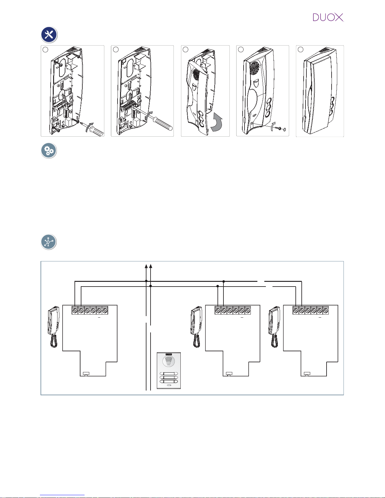
CONNECTIONS
B, B : Bus DUOX: Power, data and audio .
T, -: Connection House entrance „door bell.“ (P1).
A, -: Call extension connection or light and bell activator.
F1: Button for additional functions. It provides a negative upon being activated.
You will fi nd
more details in „LOFT Telephone Operation - Auxiliary function F1“.
Connection
DIAGRAMS
TELEPHONE Installation
3 4 5
1
2
Wiring: 2 non-polarised wires.
B
B
B
B
SW5
A
B B T
F1
SW5
A
B B T
F1
SW5
A
B B T
F1
P1 (T, -): You can place an external button to make a call to the „Door bell“ (this bell would
replace the ding-dong of the home entrance).
Notes:
- The doorbell can not be changed and is different from those selected for entry panels or
guard unit.
- The do not disturb function silences this tone.
- Y ou can program the phone´s address with this button. See chapter: Programming the phones
address via the doorbell.
Page 5
Page 5
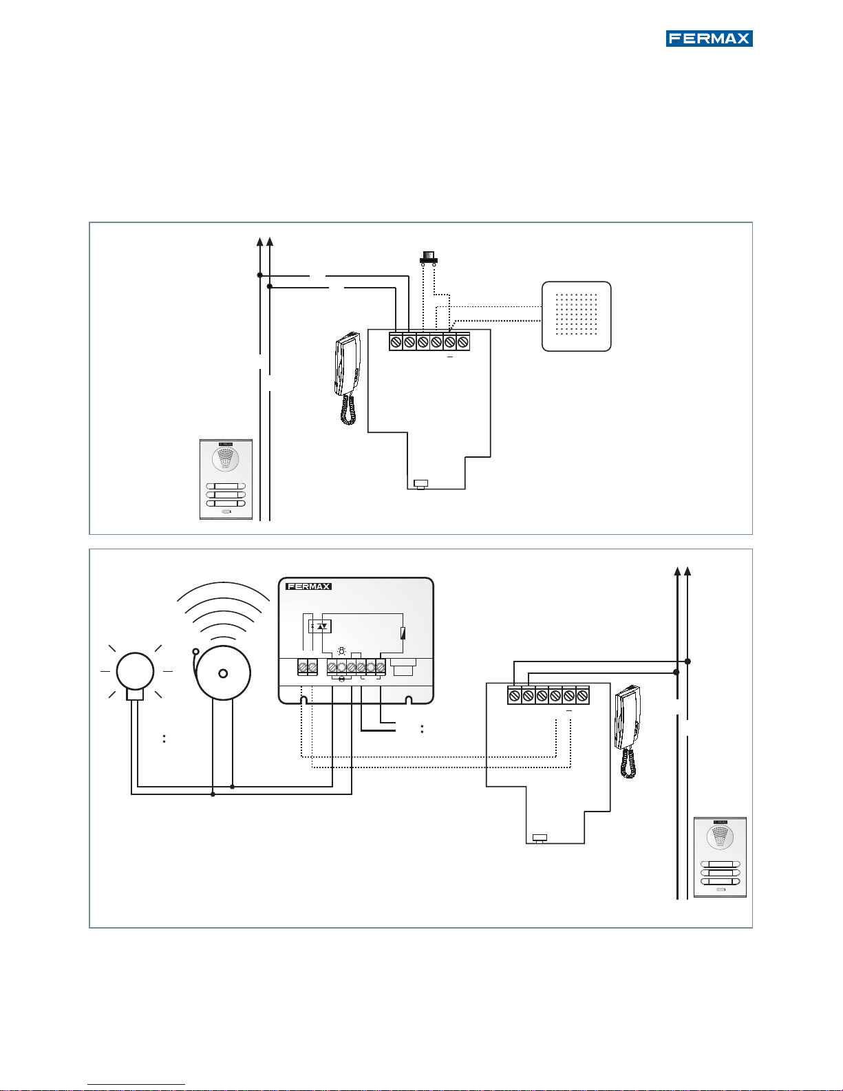
B
B
B
B
SW5
A
B B T
F1
P1
Call extension
-A+A
Red
F1 2A
2A.
Max. 2A
+A -A
110-240Vac
50-60Hz
REF. 2438
ADS LIGHT COMMANDER
ACTIVADOR DE LUCES ADS
110-240Vac
110-240Vac
SW5
A
B B T
F1
B
B
A, -: The telephone has these terminals for connecting a call extension ref. 2040 or a light
and doorbell activator. 2438 it is activated when a call is received from the entry
panel, reception and the home´s door.
Note: If the call disconnection (do not disturb mode), is activated, the terminal will continue
working. Through this, the same tone sounds as that confi gured for the call answering tone
from the panel, guard unit or doorbell.
Page 6

Page 6
TECHNICAL FEATURES
Dynamic resist. 50
Call Ring tone Selection
Microphone: Electret
Operating Temperature
Power supply (non-polarised)
Consumption (±5%)
in standby + led
maximum
Loudspeaker
Maximum number of terminals per residence
Telephone address: 6 decimal digits
Number of conversation channels: 2 per BUS. (Only audio installations)
-5º, +40ºC
1.75“ 16
3
000001...999999
18 Vdc
< 15 mA
190 mA.
Page 7

Page 7
PROGRAMMING THE LOFT DUOX EXTRA TELEPHONE
AVAILABLE FUNCTIONS
CAPACITIES
· Number of terminals per residence: maximum 3. Properly suit consumption to the power
source.
· Number of terminal addresses per sub-block: 99.
· Number of terminal addresses per block: 9999.
· Number of blocks: 99.
· Address for each telephone: 6 decimal digits: 000000 .. 999999. The address 000000 is the
default address and the telephone does not work.
· Number of conversation channels: 2 per BUS. (If the installation only has audio amplifi ers).
· Wiring: 2 non-polarised wires, depending on the wire, distances and terminal charges are
stipulated.
· Number of different optional ringtones: 5.
· Call Volume Regulation.
· Input and output audio volume regulation.
· Maximum conversation time. 90 seconds
· Maximum time to pick up on receiving the call: 30 seconds
· Maximum time to programme the telephone: 2 minutes.
There are two options to program the phone:
a) From the Panel.
b) From the Doorbell.
The functions available on the DUOX Extra telephone are summarised in the following list:
· Call Reception
· Open door
· Call to reception
· Ringtone selection
· Programming from the panel or from the doorbell
· Audio connection upon picking up
· Volume regulation
· Auxiliary F1
· Auxiliary F2 function
· Doorbell
· Light and Doorbell Activation
Page 8

Page 8
Programming Button
a) Programming a telephone address from the entry panel (main).
LED
< 2,5 min
5
A
5
A
2
1
1. With the telephone connected and hung-up, press the programming button (you will hear
a beep). Upon releasing it, you will hear the entrance into programming.
*If the telephone receiver is picked-up, communication is established with the entry panel and you can
indicate in which room the operator is. You can also open the door. If the telephone is picked-up,
hang-up before performing point 2 of programming.
2. Press the call-to-residence button. A programming confi rmation is produced.
* If the new programmed address coincides with the old one, no programming confi rmation tone
sounds, but the ringtone from the panel is heard.
Notes:
- The telephone will not function until it has been programmed.
- You can check that the telephone does not have a programmed address because the led blinks.
- You can also check that the telephone does not have a programmed address by picking up the
receiver and hanging it up again, upon hanging it up you hear a beep.
- Programming must always be done via the panel activated as MASTER. The panel’s default is to be
programmed as SLAVE. Remember that it must be programmed as MASTER before programming
the telephone. An entry panel is confi gured as a MASTER via the SW1 amplifi er button. If the SW1
button is pressed 3 times quickly , it is activated as a MASTER panel and a confi rmation tone sounds
(beep-beep). Y ou can also confi gure it via a code on the keypad. For more information see the DUOX
Panel Settings at www.fermax.com.
- The panel deactivates itself from master mode following the same activation procedure: 3 quick
presses of the SW1 button. A deactivation tone sounds (beep-bop). You can also confi gure it via a
code on the keypad. For more information see the DUOX Panel Settings at www.fermax.com.
- If there is a guard unit, it must be in night mode.
Page 9

Page 9
b) Programming the phones address via the doorbell
Note: Only if the phone has not been previously programmed, that is, if no address has been saved.
Telephone not yet programmed, red LED blinks.
With the telephone connected and hung-up:
1. Press the door bell or short terminals “T”
and “-”.
Upon performing this operation you hear a
doorbell.
Note: Optional: pick up the telephone to establish
communication with the entry panel and you can
inform the operator which residence s/he´s in.
B
SW5
BTA F1
5"
¸
B
SW5
BTA F1
2. After 5 seconds short or maintaining the
door bell pressed, the entering programming tone sounds.
After this moment you can stop shorting or
pressing the door bell. While in this mode:
3. Press the button/residential call code from
the panel. A confi rmation tone will sound
on the telephone. The telephone is programmed, (red led off)
Note: - The time from which you hear the confi rma-
tion beep for entering in telephone programming,
and the call is made from the panel to program
the phone´s address, must be less than 2 and half
minutes.
Doorbell
Doorbell
Page 10

Page 10
LOFT DUOX EXTRA TELEPHONE SETTINGS
Ringtone Selection.
The telephone allows you to select different ringtones for calls from the entry panels and
calls made from reception.
Accessing „Ringtone Selection“ Mode
We can select from 5 ringtones.
1. From panel: With the telephone in standby and hung-up, press the F2 button (you will
hear a beep), if maintained pressed for 5 seconds you will hear the current melody . Every
time you perform a new short pulsation in F2, you pass on to the next melody. Upon
arriving at the 5th melody, it returns to the 1st one.
2. From reception (guard unit): With the telephone in the ringtone selection menu from
the panel, if you maintain the F2 button pressed for 5 seconds you will hear the current
ringtone from the reception. Every time you perform a new short press of F2, you pass
on to the next ringtone. Upon arriving at the 5th ringtone, it returns to the 1st one.
- You can also exit the reception ringtone menu after inactivity for
10 seconds (storing the last ringtone played). The exit is confi rmed with a single
beep.
BEEP
F2
F2
5"
¸
F2
F2
F2
5"
¸
F2
F2
BEEP
10"
¸
Exit
Exit
10"
¸
- You can also exit the reception
ringtone menu from the panel, after
inactivity for 10 seconds (storing
the last ringtone played). The exit is
confi rmed with a single beep.
- If you maintain
the F2 button
pressed for 5
seconds you
will exit the reception ringtone
menu, returning
to standby and
storing the selected ringtone.
The exit is confirmed with a double
beep.
Notes:
F2
5"
¸
BEEP BEEP
Page 11

Page 11
Call Volume Regulation
The telephone allows for call ringtone volume regulation and the output audio volume.
Starting from standby mode and with the receiver hung-up, use the potentiometer to adjust
the call volume to any setting between the maximum and minimum levels.
Setting the call volume to minimum provokes acall disconnection or
Do not disturb mode.
In this mode the led remains lit up. If you receive a call the ringtone does not sound but
you can connect with the entry panel and open the door.
With the telephone in conversation mode you can slide the potentiometer to change the
input audio volume to one of the 8 possible levels. In this case the volume level of the
ringtone does not change.
LED
POTENTIOMETER
Auxiliary function F1
F1 confi gured as exit.
· It provides a negative upon being activated.
Notes:
- From the telephone you can activate an auxiliary relay connected to a F1 terminal for an extra
function such as the landing light, alarm activation, etc.
- When you press the F1 button the telephone generates a beep and via the bus transmits a command to activate a Duox relay (if installed). Simultaneously the F1 terminal provides a negative,
as the button is pressed.
Notes:
- The call volume setting affects all ringtones generated by the telephone: entry panels and doorbell.
- To hear the selected setting you can:
· make a call from the entry panel.
· enter ringtone selection mode.
- Call volume regulation does not affect the incoming audio settings.
- If during call volume regulation the potentiometer is turned down to
its minimum level, a constant red led will light up to indicate that the
call has been disconnected (Do not disturb mode).
-The disconnection affects all ringtones generated by the telephone.
- If you want to disconnect the call, the call extension sounds or the
lights and bell activator is activated, the terminal will continue to work.
Through this, the same tone is sounded as that confi gured for the call
answering tone from the panel, guard unit or doorbell.
- To re-activate the call, you must move the potentiometer above the
minimum level.
Page 12

Page 12
Auxiliary function F2.
From the phone you can activate an auxiliary device connected to the Duox bus. For this
you must perform a short press of the F2 button (less than 5 seconds otherwise it enters
into the ringtone selection function).
When you press the F2 button the telephone generates a beep and a command is transmitted
via the bus for activating an auxiliary device via a Duox relay (if installed).
Resetting Parameters.
The installer reset sets ALL telephone values to default.
With the telephone connected and hung-up:
1. Press the F2 button and keep it pressed
for 5” First you will hear a beep and after
5” you will hear the confi gured panel tone.
At this moment, you can stop pressing F2.
While in this mode:
Note: If there is a guard unit, it must be in night mode.
1. BEEP
5"
¸
2.
2. Press the F1 button and the button
simultaneously for 15 seconds until you
hear a double tone (BEEP BEEP) and
release.
Note: Since reset deletes the programmed address,
when the LED is blinking it indicates that the reset
has completed.
BEEP BEEP
15"
¸
+
Page 13

Page 13
Operation
LED
OPERATING THE LOFT DUOX TELEPHONE
Buttons
POTENTIOMETER
F1, F2: Additional functions. (Assigned by the installer).
· F1: From the telephone you can activate a duox auxiliary relay connected to a F1
terminal for an extra function such as the landing light, alarm activation, etc.
· F2: You can activate an auxiliary device connected to the bus via a duox relay.
Options:
F1:
- From the telephone you can activate a duox auxiliary relay (connected to a F1 terminal) for an extra function such as the landing
light, alarm activation, etc.
F2:
- From the telephone you can activate an auxiliary device connected
to the bus via a duox relay.
F1 and F2 (additional functions)
Ask your installer which function must be programmed.
F1
F2
Door open /call reception button (function available depending on type of
installation).
· While in conversation with the Entry Panel (telephone picked-up), pressing it
will activate the open door.
· Upon receiving the call (telephone hung-up) If the phone is not answered you
have 30 seconds to open the door.
· When you press this button with the telephone hung-up (standby) a call will be
made to the reception (where one exists).
Page 14

Page 14
Answering a call.
· When the call button on the Entry Panel/Guard Unit is pressed a call tone is emitted both
from the entry panel and the telephone.
· On receiving a call on the telephone the user has 30 seconds to answer.
· Audio activation: Upon picking up the phone within the established time, communication
will be established with the entry panel that made the call.
· Hang-Up: Hang-up the phone´s receiver to end communication, if not the conversation
will be disconnected after 90 seconds.
· Auto-Start: This function is possible with the panel in the same block; if the panel is in
standby and programmed as “0”; and if there is a conversation channel available, (if it
isn´t available, upon hanging up you will hear a busy tone for 15 seconds). For more
information see the DUOX Panel Settings at www.fermax.com.
Note:
- If the phone is not programmed, the auto-start will not function.
- In case you have made a call from the 00 panel to another home and you are within the waiting
time to pick-up (30 seconds), you can not communicate with the 00 panel.
¸
max. 30
Seg./Sec./Sek.
Call
¸
max. 90 Seg./Sec./Sek.
bla bla
bla ...
bla bla
bla ...
bla bla
bla ...
Answering a call
1
2
Page 15

Page 15
Notes:
- The conversation is private, no other terminal can hear it.
- While the audio channel is open the input audio can be regulated with the potentiometer, without
affecting the call volume. The selected setting will not be altered if the call volume is subsequently
adjusted.
- The auto-start function is always used on the panel from the same block confi gured as 0, except
where a call is received from another panel. Once the conversation is over, auto-start will activate
on the secondary panel for 15 seconds. After this time it will do so on the 0 panel in the same block.
- If there are various telephones in the same home, the audio will only come from the fi rst one
picked-up, leaving the remaining phones in standby.
- If more than one telephone has picked-up and you receive a call, none of them may enter in
conversation unless they hang-up and pick-up again and none is previously in conversation.
Opening the Door
When a call is received from the entry panel, you can open the door at any time, by pressing the
button.
In conversation (telephone picked-up). If picked-up, it can occur during the conversation
with an entry panel. The lock is released on the panel that called.
Upon receiving the call (telephone hung-up) If the phone is not answered you have 30
seconds to open the door.
¸
max. 30
Seg./Sec./Sek.
¸
max. 90
Seg./Sec./Sek.
Auto-Start
Page 16

Page 16
Canceling Ringtones (do not disturb function)
If during call volume regulation the potentiometer is turned down to its
minimum level, a constant red led will light up to indicate that the call
has been disconnected, do not disturb function.
The disconnection option affects all ringtones generated by the telephone:
To deactivate ringtone cancellation, you must move the potentiometer
above the minimum level. The led will return to its previous status.
Note:
- If disconnected, the call extension sounds or the lights and bell activator is
activated. Through this, the same tone is sounded as that confi gured for the
call answering tone from the panel, guard unit or doorbell.
- For more operating information: See See “Call Volume Regulation”.
LED
POTENTIOMETER
bip
Beep
Call to reception
This is done bypressing the
button when the telephone is in standby and hung-up. The
call to reception is made to the reception that is activated for the block in which the telephone
is, sounding a beep when the confi rmation is received from this reception.
If the block´s guard unit is not active (night mode) the call to a guard unit is made to the
general guard unit if there is one active. If the installation does not have an active guard
unit, the phone will not beep.
Page 17

Page 17
Page 18

Page 18
Page 19

Page 19
Page 20

Avda. Tres Cruces, 133 • 46017 Valencia (Spain)
Telf. 96 317 80 00 • Fax 96 377 07 50
Telf. Export: 00 34 96 317 80 02
www.fermax.com• fermax@fermax.com
 Loading...