

Page 1
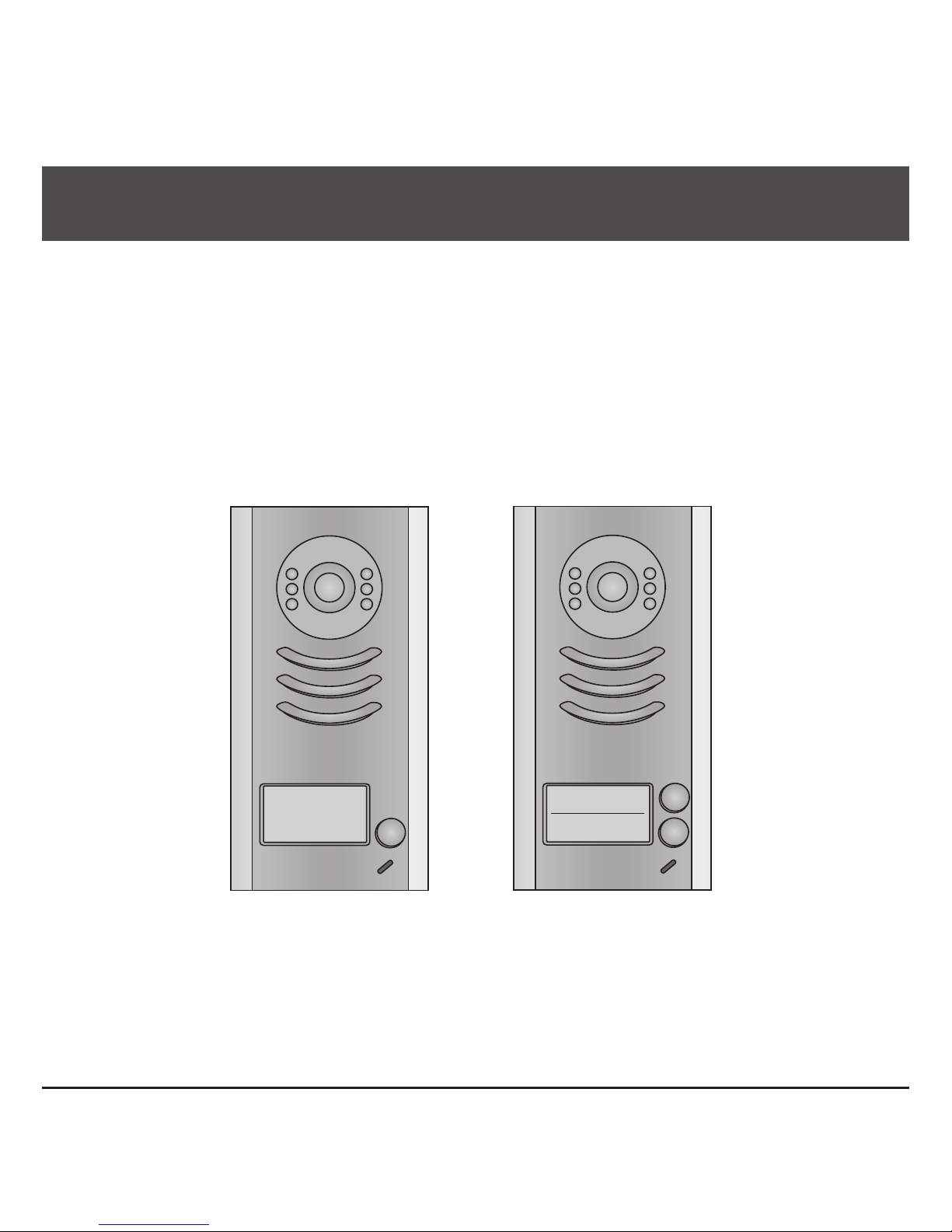
2 -Wire Intercom System
DT591/592 User Manual
DT-ENG-591/592-V1 160603
DT591 DT592
Page 2

CONTENTS
1.Parts and Functions............................................................................................. 1
2.Terminal Descriptions .......................................................................................... 1
3.Specications ...................................................................................................... 2
4.Mounting .............................................................................................................. 2
4.1 Mounting Without Rainy Cover ...................................................................... 2
4.2 Mounting With Rainy Cover ........................................................................... 3
4.3 Placing Name Label ...................................................................................... 3
5.System Wiring and Connections ......................................................................... 4
5.1 Basic Connection........................................................................................... 4
5.2 Electric Lock Connection ............................................................................... 4
5.2.1 Door Lock Controlled with Internal Power ............................................ 4
5.2.2 Door Lock Controlled with Dry Contact ................................................ 5
5.2.3 Unlock parameter setting(set on monitor) ............................................. 5
5.3 Multi Doorstations Connection....................................................................... 6
5.4 Multi Monitors Connection ............................................................................. 7
5.4.1 Basic IN-OUT Wiring Mode ................................................................. 7
5.4.2 With DBC4A1 Wiring Mode ................................................................. 8
6.Setup ................................................................................................................... 9
6.1 DIP Switches Settings of Doorstation ............................................................ 9
6.2 Ringtone Mode Settings ................................................................................ 9
6.3 Unlock Time Settings ..................................................................................... 11
7.Cables Requirements .......................................................................................... 12
Page 3
-1-
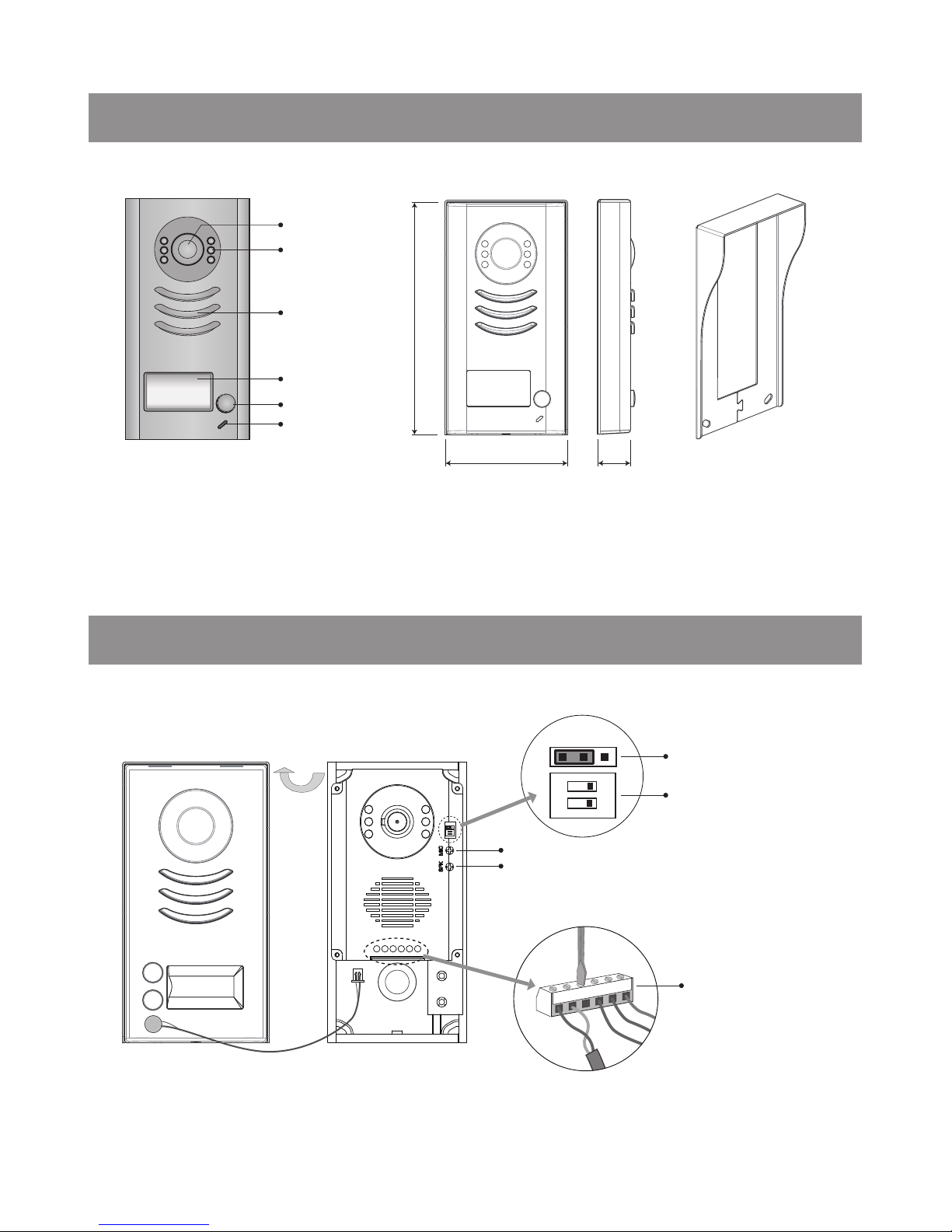
1.Parts and Functions
Rainy Cover
Camera Lens
Night View LED
Speaker
Nameplate
Call Button
Microphone
3.54 in
6.93 in
0.91 in
2.Terminal Descriptions
BUS
PL
S1+ S2+ S-
1 2
ON
12
ON
MIC adjustment
Lock Control Jumper
Doorstation Code DIP
Main Connect Port
1 2 3
SPK adjustment
Note: DT592 has two call buttons.
Page 4
-2-
•
Lock Control Jumper:
To select the lock type: see 5.2.1 , 5.2.2
•
Doorstation Code DIP:
Total 4 doorstations can be supported,see 6.1
•
Main Connect Port:
To connect the bus line and the electronic locks.
• BUS: Connect to the bus line, no polarity.
• PL: External lock power input, connect to the power positive(power +).
• S1+, S2+: Lock power(+) output, to connect 2 locks.
• S-: Lock power(-) output, connect to the power(-) input of locks(only when using the camera to
power the locks, if using the external power supply for the locks, the S- will not be connected).
3.Specications
Lock Power supply: 12Vdc, 300mA(Internal Power)
Power Consumtion: 1W in standby, 12W in working
NO, COM dry contact: Max. 48V dc 1.5A
Unlocking time: 1 to 9 seconds, set by Monitor
Working temperature: -10ºC ~ 45ºC
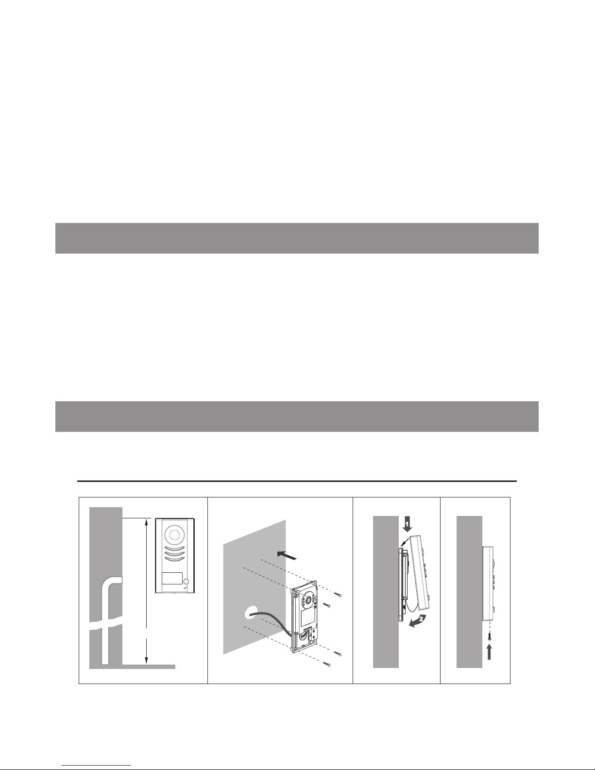
4.Mounting
4.1 Mounting Without Rainy Cover
63-65 in
1
2
1 2 3 4
Page 5

-3-
4.2 Mounting With Rainy Cover
63-65 in
Rainy cover
The distance between the
top of main unit and rain
cover should be not less
than 3mm.
Rainy cover
Main unit
≥3mm
Main unit
1
2
1 2
3
4
12
ON
4.3 Placing Name Label
Move the plastic cover away
to open the transparent name
label cover, insert a name
paper, then put the plastic
cover back to the panel.
name label
12
ON
Page 6

-4-
5.1 Basic Connection
5.System Wiring and Connections
Doorbell Button
Switch
-
+
12
ON
L1 L2 PL S1+ S2+ S-
+
-
DPSDR-30-24
Code=00, DIP6=on
1 2 3 4 5 6
ON DIP
L2
L1
DIP Switches
5.2 Electric Lock Connection (NOT RECOMMENDED). See Page 6.
5.2.1 Door Lock Controlled with Internal Power
Note: NOT RECOMMENDED unless the door lock is less than 250mA. Please
see Part 5.2.3 on Page 6 for HOOKING UP A DOOR RELEASE.
connect one lock connect two locks
Note:
1. Electronic lock of Power-on-to-unlock type should be used.
2. The door lock is limited to 12V, and holding current must be less than 250mA.
3. The door lock control is not timed from Exit Button(EB).
4. The
Unlock Mode
Parameter of Monitor must be set to 0 (by default).
EB
*
LOCK
BUS PL S1+ S2+ S-
LOCK
2
nd
1
ST
2
nd
EB
*
1
ST
Jumper position in
Connect two locks
1-2
EB
*
LOCK
BUS PL
S1+S2
+
S-
Jumper position in
Connect one lock
1-2
Page 7

-5-
5.2.2 Door Lock Controlled with Dry Contact
Note:
1. The external power supply must be used according to the lock.
2. The jumper must be taken off before connecting.
3. Setup the
Unlock Mode
of Monitor for different lock types.
• Power-on-to-unlock type:Unlock Mode=0 (by default)
• Power-off-to-unlock type:Unlock Mode=1
LOCK
BUS PL
S1+S2
+
S-
Take off the Jumper
POWER
SUPPLY
LOCK
BUS PL
S1+S2
+
S-
Take off the Jumper
POWER
SUPPLY
connect one lock connect two locks
Page 8

-6-
5.2.3 Hooking Up a Door Release
Page 9

-7-
5.3 Multi Doorstations Connection
12
ON
L1 L2 PL S1+ S2+ S-
12
ON
L1 L2 PL S1+ S2+ S-
12
ON
L1 L2 PL S1+ S2+ S-
12
ON
L1 L2 PL S1+ S2+ S-
1 2
ON
1 2
ON
1 2
ON
1 2
ON
1# Camera
ID=00
ID=10
ID=01ID=11
2# Camera3# Camera4# Camera
DBC4A1
A B C D
OFF
ON
Impedance
switch
+
-
DPSDR-30-24
Page 10

-8-
5.4.1 Basic IN-OUT Wiring Mode
5.4 Multi Monitors Connection
ID=00
1 2
ON
Code=14
Code=15
NOTE:Here we take DT47MG(the monitor) for example.
Code=0
+
-
DPSDR-30-24
Page 11

-9-
5.4.2 With DBC4A1 Wiring Mode
Code=0
OFF ON
OFF ON
DBC4A1
A B C D
DBC4A1
A B C D
Impedance
switch
Impedance
switch
NOTE:Here we take DT47MG(the monitor) for example.
Code=2
Code=1
Code=3
Code=12
Code=14
Code=13
Code=15
ID=00
1 2
ON
+
-
DPSDR-30-24
Page 12

-10-
6.Setup
6.1 DIP Switches Settings of Doorstation
Total 2 bits on the DIP switches can be congured.The switches can be modied either before or after
installation.
Bit state Descriptions
Default setting, ID = 0(00), set to the rst Door Station.
ID = 1(10), set to the second Door Station.
ID = 2(01), set to the third Door Station.
ID = 3(11), set to the fourth Door Station.
1
2
ON
1 2
ON
1 2
ON
1 2
ON
ON(1)
=
OFF(0)
=
ON
ON
The system supports three ringtone modes: [1]one ringtone, [2]continuous ringtone, [3]forbid ringtone. The
default is one ringtone.
Note:Monitors response button A must set the user code from 0
to 15.and button B set the user code from 16 to 31.
A
B
A
6.2 Ringtone Mode Settings
Page 13

-11-
1)Power-on within 5 seconds;
2)Press and hold "B" button for 3
seconds, it will enter the setting the
state of prepare.
Indicator Buzzer
beep+,beep
(ash)
Press and hold "B" button for 3
seconds, it will enter the state of
ringtone mode setting.
Indicator Buzzer
beep+
(off)
Followed by pressing the "B" button,
each time you press "B" button to
replace the ringtone mode;
Note:The ringtone mode will cycle
between [1] [2] [3].
Indicator Buzzer
beep
[1]:
beep,beep
[2]:
beep,beep,beep
[3]:
(ash one)
(ash twice)
(ash 3 times)
Note: In all steps, if there isn’t any operation within 5s, or press Call button, it will exit the
setting.
Page 14

-12-
6.3 Unlock Time Settings
1)Power-on within 5 seconds;
2)Press and hold "B" button for 3
seconds, it will enter the setting the
state of prepare.
Indicator Buzzer
beep+,beep
(ash)
Press and hold "A" button for 3
seconds, it will enter the state of
unlock time setting.
Indicator Buzzer
beep+
(off)
At this time press and hold "B"
button,timing starts; release "B"
button to end the timing. The time of
press and hold "B" button equal to
unlock time.(Timing Unit: 1s)
Indicator Buzzer
beep once
per second
(ash once per second)
The unlock time can be set to 1~30 seconds. The default is 1s.
Note: In all steps, if there isn’t any operation within 5s, or press Call button, it will exit the
setting.
Page 15

-13-
7.Cables Requirements
The maximum distance of the wiring is limited in the DT system. Using different cables may also affect the
maximum distance which the system can reach.
The farest monitor
B
A
C
DBC4A1
monitor
monitor
monitor
with two or four monitors
+
-
DPSDR-30-24
Note: The thicker the copper wire is, the longer distances will be. Best wire to use is 18 Guage twisted,
while Cat 5 or 6 are not recommended.
Cable Usage A B C
Twisted cable 2x0.00116 sq.in
196ft 196ft 98ft
Twisted cable 2x0.00155 sq.in
262ft 262ft 131ft
Cable Usage A B C
Twisted cable 2x0.00155 sq.in 229ft 98ft 65ft
Twisted cable 2x0.00233 sq.in 229ft 164ft 98ft
When Monitor quantity < 20
When Monitor quantity > 20
Page 16

The design and specications can be changed without notice to the user. Right to interpret
and copyright of this manual are preserved.
 Loading...