

Page 1
Ref. 7960
12 V
J2
SW1
ON2
3
1
RX
P
T
TX
14 s.12 s.10 s.8 s.
231
132
231
231
12 V
J2
SW1
ON2
3
1
RX
P
T
TX
8 s
W
O
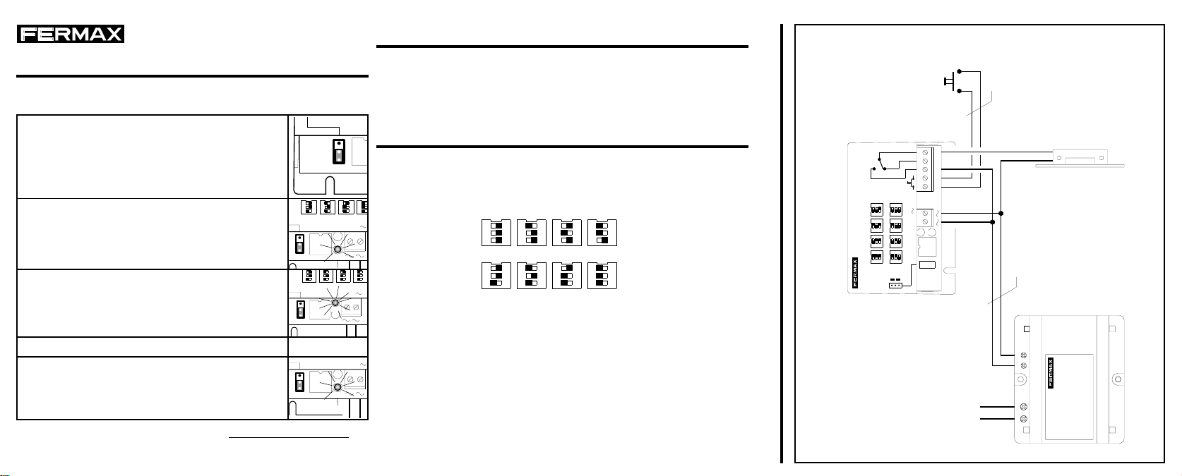
PROGRAMACIÓN RECEPTOR RF CHALET
Siga los pasos mostrados en la tabla para programar los tele-
mandos:
1. Para la programación de los códigos, alimente el módulo con el puente J2 en la posición
P.
J2
2. Nada más alimentar el receptor, el led verde
permanecerá encendido y el led rojo parpadeará (con intervalos de un segundo) tantas veces como códigos hayan programados (si programa por primera vez no debe parpadear).
3. El led verde comenzará a parpadear , esperando la entrada de nuevos telemandos.
4. Pulse el botón del mando elegido.
5. El led rojo parpadeará una vez indicando que
la programación ha sido satisfactoria.
Apague el equipo y coloque el puente J2 en la
posición T.
Para borrar un código, es necesario borrar toda la memoria. La
memoria se borra pulsando el botón de apertura de puerta con el
receptor en modo programación.
132
N
231
OG.
231
1
T
RX
ON2
3
P
J2
TX
SW1
BOTÓN DE APERTURA DIRECTA
Utilice las bornas B, - para conectar un pulsador de apertura de
puerta, que actuará del mismo modo que si se hubiese recibido un
código válido cada vez que se pulse.
.
TIEMPO DE ACTIVACIÓN
T
2
31P
Utilice el microinterruptor SW1 para establecer el tiempo de
S
apertura de puerta (activación del relé), siguiendo el esquema
mostrado a continuación. La parte sombreada indica la posición del
interruptor.
132
231
14 s.12 s.10 s.8 s.
12 V
231
.
La opción FLIP-FLOP se utiliza para que el interruptor quede
permanente cerrado hasta que se vuelva a pulsar el botón del
telemando.
132
231
132
6 s.4 s.2 s.FLIP-FLOP
231
231132
14 s.12 s.10 s.8 s.
EXIT PUSHBUTTON
PULSADOR SALIDA
( INTERIOR / INNER )
C
NCNO
B-
6 s.4 s.2 s.FLIP-FLOP
14 s.12 s.10 s.8 s.
231132
12 V
231
132
132
231
SECURITY RECEIVER
RECEPTOR SEGURIDAD
231
132
ON
REF.7960
REF.7960
RF RECEIVER
RECEPTOR RF CHALET
PROG.
TX
RX
ON2
SW1
3
1
T
P
J2
ESQUEMA DE CABLEADO
220 V
2
0.5 mm.
2
Cod.94191 V.10/98
1 mm.
SEC. 12Vac
PRIM 220Vac
ELECTRIC LOCK
REF.2911
ABREPUERTAS
REF.8787
ALIMENTADOR
Page 2
Ref. 7960
12 V
J2
SW1
ON2
3
1
RX
P
T
TX
14 s.12 s.10 s.8 s.
231
132
231
231
12 V
J2
SW1
ON2
3
1
RX
P
T
TX
8 s
W
O
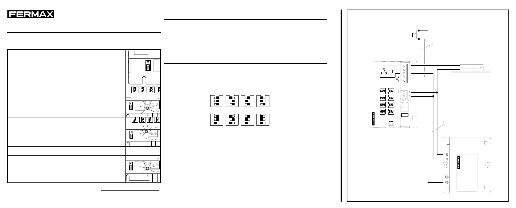
PROGRAMMING THE RF RECEIVER
Follow the steps shown in the table below for programming the
transmitters:
1. To program the codes, supply the module with
the jumper J2 into P position.
J2
2. Once the reciever is supplied, the green led
will remain lightening and the red led will flash
(in shorts of 1 second) as many times as codes
programmed in the system (when programming
first time it will not flash).
3. The green led will flash indicating that it is ready
to store new codes (transmitters).
4. Press the button in the transmitter.
5. The red led will flash once to indicate that the
system has recognised the new device.
Switch-off the module and put the jumper J2
back to the position T.
To erase a code, it is necessary to erase the whole memory.
The memory is erase by pressing the door releasing button when
the module is in programming mode.
132
N
231
OG.
231
1
T
RX
ON2
3
P
J2
TX
SW1
DIRECT DOOR RELEASE BUTTON
The terminals B and - are used to connect a pushbutton to open
directly the door, which will give exactly the same response from the
system that if a valid code would be received.
.
ACTIVATION TIME
T
2
31P
Use the microswitch SW1 to set up the door releasing time (relay
S
activation), following the diagrams shown below. The filled portion
indicates the switch position.
132
231
14 s.12 s.10 s.8 s.
12 V
231
.
The FLIP-FLOP option is used to keep the contacts closed until the
pushbutton in any transmitter is pressed again.
132
231
132
6 s.4 s.2 s.FLIP-FLOP
231
231132
14 s.12 s.10 s.8 s.
6 s.4 s.2 s.FLIP-FLOP
231132
231
132
132
231
SECURITY RECEIVER
RECEPTOR SEGURIDAD
231
132
ON
REF.7960
REF.7960
RF RECEIVER
RECEPTOR RF CHALET
WIRING DIAGRAM
EXIT PUSHBUTTON
PULSADOR SALIDA
( INTERIOR / INNER )
C
NCNO
B-
14 s.12 s.10 s.8 s.
12 V
TX
RX
ON2
SW1
3
1
T
P
J2
PROG.
220 V
2
0.5 mm.
2
1 mm.
ABREPUERTAS
SEC. 12Vac
PRIM 220Vac
ELECTRIC LOCK
REF.2911
REF.8787
ALIMENTADOR
 Loading...